A Study on the Improved Capacitor Voltage Balancing Method for Modular Multilevel Converter Based on Hardware-In-the-Loop Simulation

1
Department of Electrical Engineering, Pusan National University, Pusan 46241, Korea
2
Korea Electrotechnology Research Institute, Changwon 51543, Korea
*
Author to whom correspondence should be addressed.
Electronics 2019, 8(10), 1070; https://doi.org/10.3390/electronics8101070
Submission received: 21 August 2019
/
Revised: 11 September 2019
/
Accepted: 19 September 2019
/
Published: 21 September 2019
(This article belongs to the Special Issue Hardware in the Loop for Electrical Systems: Techniques, Algorithm and Circuits)
Abstract
:In the power industry, hardware in-the-loop simulation (HILS) based on a real-time digital simulator (RTDS) is important technology for modular multilevel converter (MMC)-based high-voltage direct current (HVDC) power transmission. It is possible in real time to verify various fault situations that cannot be predicted by the software-in-the-loop simulation (SILS). This paper introduces the implementation methodology of sub-module (SM) capacitor voltage balancing for a MMC-HVDC physical control system based on field-programmable gate array (FPGA), which has the advantages of high-speed parallel operation and validates the reliability and accuracy of MMC-HVDC control when this control system is operated with RTDS. The characteristics of conventional capacitor voltage balancing methods, such as the nearest level control (NLC) with full sorting method, the NLC with reduced switching frequency method, and the tolerance band (TB) method, implemented on a physical control system based on this implementation methodology, are compared and analyzed. This paper proposes the improved capacitor voltage balancing method for MMC-HVDC transmission. Finally, the proposed capacitor voltage balancing method is compared with conventional methods to analyze performance in real-time to demonstrate that the proposed method is better than the conventional methods.
1. Introduction
The development of voltage source converter (VSC)-type high-voltage direct current (HVDC) transmission systems is becoming an important technology in the power transmission industry [1]. Direct current (DC) transmission is economical because the insulation level of the line is low. In addition, it has the effect of dividing the power system and is advantageous in terms of power loss at long distances when compared to alternating current (AC) transmission. In particular, since it has high controllability, it is possible to apply various control methods suited to the characteristics of AC [2]. Therefore, it is expected that more HVDC control methods will be studied in the future. However, in order to build HVDC transmission systems, initial simulations are needed to verify a system because they require a huge amount of money. The simulation method is largely divided into two different methods. The first method is the software-in-the-loop simulation (SILS) method, which designs the controller, topology, and various devices by a software-based design. The second is the hardware-in-the-loop simulation (HILS) method, which interfaces with a real-time digital simulator (RTDS) to create a physical control system and approximate an actual system at the hardware level. These two methods, each with a variety of software tools, perform various functions for the purpose of the simulation [3,4]. HILS consists of a RTDS that has been proven in the power industry and a computer aided design (CAD) program that designs it. In addition, the RTDS and physical control system must be configured to interface with each other. Therefore, this paper introduces implementation of the HILS system for a point-to-point (P2P)-type modular multilevel converter (MMC)-based HVDC by designing a physical MMC control device based on a field-programmable gate array (FPGA) and verifies the performance of the control device [5].
In order to construct the HILS for power converters, it is necessary to perform precise verification of each part while constructing the interface between the real-time simulator (e.g., RTDS or OPAL-RT) and the physical control system [6,7,8,9]. These parts can be divided into three categories: Platform, communication, and algorithm. It is necessary to collect data based on many experiments to see how all of the parts react under various conditions. The platform should be designed by defining the hierarchy of the controllers. In addition, a proper communication system should be constructed for mutual cooperation among these layers. Furthermore, it is necessary to consider the timing of the communications between layers. Experiments should also be conducted to find alternatives to the packet loss that can occur in each segment. Once the hardware design of the HILS system has been completed, software-based alternatives to the various problems that arise in the controller’s internal computing system should be prepared. When the AC grid voltages are unbalanced, circulating current suppression control algorithms should be selected according to the computation speed and the calculation performance in the physical control system [10]. In addition, various capacitor voltage balancing methods are implemented as FPGA logic, which can operate in parallel [11]. Furthermore, a method to design a 240 MW and 1 GW-class MMC-HVDC with optimal switching frequency and ripple is introduced.
A low-level controller, such as modulation methods and capacitor voltage balancing methods, must be designed in consideration of the timing of the control logic because it must be implemented in the FPGA for high-speed parallel operation. Since HILS can identify and solve various problems that can occur in real systems, it can be the most reliable verification method before making an actual large capacity MMC-HVDC. Finally, this paper compares and analyzes characteristics of capacitor voltage balancing methods, such as the nearest Level control (NLC) with full sorting method, the NLC with reduced switching frequency method, and the tolerance band method, implemented on a physical control system. Additionally, the proposed new capacitor voltage balancing method is compared with conventional methods to analyze performance for a 240 MW and 1 GW-class MMC-HVDC system.
2. Modular Multilevel Converter
2.1. Topology of Modular Multilevel Converter
As shown in Figure 1, the structure of a three-phase grid-connected modular multilevel converter (MMC) consists of six arms [12]. Each phase has two arms. Each arm has one inductor and N sub-modules (SM) in the form of a half-bridge connected in a series. Each SM consists of one capacitor and two insulated gate bipolar transistors (IGBTs) and controls the onoff state of the switches, S1 and S2, to produce a desired AC or DC voltage. S1 and S2 are complementary to each other. When S1 is ON and S2 is OFF, the capacitor is charged or discharged depending on the direction of the arm current. Conversely, when S1 is OFF and S2 is ON, the capacitor is bypassed and the voltage value remains unchanged. In other words, the control method of the MMC is affected by the switching pattern of the SMs [13].
To balance the voltages of the upper and lower arms of each phase, the voltage across the SMs in each arm must be shared. Therefore, the voltage reference must be calculated to select a number to switch the SMs in each arm [14]. Figure 2 shows an equivalent circuit of a MMC. State equations are obtained based on this equivalent circuit and the voltage references of each arm are finally obtained as follows [15]:
In these equations, is the a, b, and c phase and is the DC voltage. In addition, is the upper arm voltages and is the lower arm voltages. is the resistance of each arm and is the inductance of each arm. Equations (1) and (2) are the voltage equations of the upper and lower arms for , which was defined as the phase voltages.
If Equations (1) and (2) are subtracted and rearranged with Equation (3), which was defined as the imaginary inner alternating voltages in Reference [16], and Equation (4), which was defined as the phase currents , Equation (5) is obtained.
If Equations (1) and (2) are summed and rearranged with Equation (6), which was defined as the difference currents , Equation (7) is obtained. Hence, , which was defined as the total sum of the internal voltages of each phase, is given as:
By rearranging Equations (3) and (8), , which was defined as the voltage references of the upper arm, and , which was defined as the voltage references of the lower arm, can be obtained as follows:
2.2. Specification Design of MMC
As shown in Figure 3, the control system of this paper is classified into a high-level control that obtains voltage references through power control, current control, circulating current suppression control, and low-level control, which performs voltage balancing by receiving voltage references.
To determine the power transmission capacity of a MMC-HVDC system, the number of SMs and the control period must be determined first. The number of SMs is determined by the DC transmission capacity and the capacitor capacity of a SM. The control period should be designed so that the voltage level obtained by the voltage references can be changed by one level per cycle. In addition, it should be designed so that both the high-level control and low-level control can be operated within a control period, as shown in Figure 4.
3. Hardware In-the-Loop Simulation
3.1. Implementation of a Physical MMC Controller
A hardware-in-the-loop simulation (HILS) between a FPGA-based physical control platform and a real-time digital simulator (RTDS) was built, as shown in Figure 5. The high-level controller was a station controller (SC), which implemented a high-level control algorithm by receiving analog signals, such as the arm currents of the MMC, the voltage of the AC grid, the current of AC grid, the voltage of the DC-link, and the current of the DC-link from the gigabit transceiver analogue output card (GTAO) mounted on the RTDS. Below the SC, there were six valve controllers (VCs) that controlled the three-phase upper and lower valves to implement the low-level control algorithm by receiving the sub-module (SM) capacitor voltages output from the MMC support unit (MSU). In addition, there were six interface boards (IBs) to intercommunicate the packets between the VCs and the RTDS. The communication between each controller was based on Xilinx’s Aurora Protocol and consisted of 5 Gbps high-speed serial communication. A grand master clock (GMC) was used as the reference clock to synchronize all of the layers.
Figure 6 is a block diagram of the high-level control methods implemented in the physical control system. First, the characteristics of the two algorithms can be verified by implementing the phase locked loop (PLL) methods using the dq-frame delayed signal cancellation (dqDSC)-PLL method and the dqDSC with moving average filter (MAF) method. As can be seen from the power and current control block, the characteristics of the inner current control and the circulating current control, which were divided into a method using a proportional integral (PI) controller in a dq frame and a method using a proportional resonant (PR) controller in an a-b-c frame, can be compared. In addition, by adding a method of injecting the 3rd harmonic to the reference voltage, it is possible to compare the characteristics of the 3rd harmonic applied and not applied in real time. All of these algorithms were implemented in FPGA logic and could be operated at high speed.
Figure 7 is a block diagram of the low-level control methods implemented in the physical control system. When receiving a voltage reference from a high-level control, the low-level control can be compared with two methods, such as a phase-shifted carrier (PSC) pulse width modulation (PWM) to modulate the voltage reference and the nearest level control (NLC) [17]. The selection methods, such as full sorting, reduced switching frequency (RSF), an average tolerance band (ATB), and a cell tolerance band (CTB) were selectively used according to the specifications and characteristics of MMC-HVDC, and the characteristics of selection algorithms can be compared [18,19]. All of these selection algorithms were implemented in FPGAs to achieve the fastest sorting completion by applying fast parallel sorting logic.
3.2. RTDS Design
As shown in Table 1, the modeling of an MMC-HVDC in a RTDS can be designed with a program called RS-CAD for the circuit design of a 240 MW system. The primary and secondary voltage of the transformer were set to 154 kV and 118 kV. The capacity of the SM capacitors was set to 6 uF, and the inductance of the arm reactors was set to 20 mH [20,21].
In addition, the modeling of 1 GW MMC-HVDC was that the primary and secondary voltage of the transformer were set to 528 kV and 460 kV. The capacity of the sub-module (SM) capacitors was set to 10 mF, and the inductance of the arm reactors was set to 50 mH as shown in Table 2. Direct current (DC).
3.3. Parallel Sorting
Parallel operation using a FPGA is indispensable for calculating high-level control and low-level control within 10 usec. Quick sorting, which is one of the fast sorting algorithms, performs recursive operations. Parallel operation of a recursive function based on FPGA hardware logic is complicated and difficult to sort in a desired time [22]. Therefore, in order to design a sorting algorithm based on a FPGA, it is necessary to select one of the most basic sorting methods, even though it is slow, such as bubble sorting, which is not implemented as the recursive. As can be seen from the time complexity , the bubble sorting algorithm has an operation speed corresponding to the worst case, where the comparison operation increases by the square of the number of data to be sorted [23]. However, if parallel sorting is performed by an even-odd bubble sorting network, as shown in Figure 8, it is possible to complete the sorting with only eight parallel comparisons of eight data. In addition, the computation time can be greatly reduced when compared with a single CPU. In other words, in order to sort - data, the sorting is completed with only - parallel comparison operations [24].
In order to implement this sorting network on hardware, it should have simultaneous access to Index 0–1, Index 2–3, Index 4–5, and Index 6–7. In the next cycle, Index 1–2, Index 3–4, and Index 5–6 are accessed at the same time because access to same memory is not possible at the same time.
Therefore, as shown in Figure 9, the data of the index addresses of two adjacent submodules that were not simultaneously accessed were read in the first cycle. After the data was compared in the second cycle, it was written to the index address of the adjacent submodules that were not simultaneously accessed in the third cycle. In other words, the sorting of 432 capacitor voltages was completed in only 434 clocks. Since the operation clock was set to 200 MHz, it was 5 nsec per clock. As a result, the calculation was completed in only 2.17 usec. Since the sorting for the capacitor selection was performed in the low-level control, a calculation time of 2.17 usec was then required once again.
4. Capacitor Voltage Balancing
4.1. Capacitor Voltage Balancing Methods for MMCs
In the low-level control, was obtained by using modulation methods based on the voltage reference and a firing pulse generated using selection methods. Modulation methods in MMC-HVDC mainly used phase-shifted carrier (PSC) PWM and nearest level control (NLC) methods, as shown in Figure 10 [25]. In particular, the greater the number of sub-modules (SM), the more the NLC method was used [26]. Therefore, in this paper, the modulation method was performed using the NLC method. Selection methods were divided into band generation term and capacitor selection term. The band generation term was an added block for varying the switching frequency, and there are various ways to generate a tolerance band. The capacitor selection term is a method to switch the SMs and is the key term for capacitor voltage balancing methods.
4.2. Band Generation
The band generation term is a step of forming a tolerance band using various information about SM capacitor voltages (e.g., average value, maximum value, and minimum value of SM capacitor voltages), so that this information is within a certain range. The most commonly used band generation methods are the average tolerance band (ATB), for which the average value of the capacitor voltages is within the allowable range, and the cell tolerance band (CTB), for which the maximum value or minimum value of the capacitor voltages is within the allowable range.
4.3. Capacitor Selection
The capacitor selection term is the step of determining which SMs are to be switched when certain information about capacitor voltages is out of the tolerance band using ATB or CTB. The ATB and CTB methods reorder capacitor voltages when specific information about capacitor voltages is out of the tolerance band, then switching the SMs with the highest capacitor voltage or the lowest capacitor voltage depending on the charging or discharging sequence [27]. When the tolerance band is set to 0%, sorting is performed on every cycle, like the full sorting method. This is similar to updating the index for the magnitude of capacitor voltages each time. Increasing the tolerance band reduces sorting of every cycle, so the number of switching cycles can be reduced by selecting the index of previously sorted capacitor voltages. In other words, the slower the time for certain information about capacitor voltages to reach the tolerance band, the lower the switching frequency.
4.4. Proposed Method
The proposed capacitor voltage balancing method is shown in Figure 11. As mentioned earlier, the capacitor voltage balancing method was divided into the band generation term and capacitor selection term. In the band generation term, the capacitor voltages were sorted and various band generation methods, such as ATB and CTB, were applied. In the paper, the average value of capacitor voltages was applied as an example to compare with the proposed method. This was the same as the conventional average tolerance band method. However, the proposed method was different from the conventional method in the following capacitor selection term. If the average value of the capacitor voltages is larger than the set band value, it can be divided by the positive term and negative term of , which is the difference between and . The positive term of turned on the SMs that had the lowest voltage when the arm current was positive among the turned off SMs and turned on the SMs that had the highest voltage when the arm current was negative among the turned off SMs. The negative term of turned off the SMs that had the highest voltage when the arm current was positive among the turned on SMs and turned off the SMs that had the lowest voltage when the arm current was negative among the turned on SMs. When the average value of the capacitor voltages was lower than the set band value, all SMs were switched off, the was initialized, and we proceed to the next sequence.
5. Results
5.1. Experimental Results
Figure 12a shows the waveform of eight capacitor voltages of SMs for the full sorting method. The voltage ripple is the smallest and the switching frequency is the greatest because it is a method that updates the switching sequence of SMs by sorting the capacitor voltages at every cycle. As shown in Figure 12b, the full sorting method has very low circulating currents. The switching frequency is affected by the control cycles and the number of SMs. Therefore, the full sorting method has a switching frequency of about 6.6 kHz in this 1 GW MMC-HVDC system, with a control period of 10 usec and 432 SMs.
Figure 13a shows the waveform of capacitor voltages for the reduced switching frequency (RSF)-type sorting method, in which the switches are turned on/off according to the previous state of SMs. When charging, the SM which the voltage is the lowest and the previous state has turned off is turned on. On the contrary, when discharging, the SM which the voltage is the highest and the previous state has turned on is turned off. Therefore, it is the capacitor voltage balancing method that has the smallest switching frequency, while having the greatest ripple. As shown in Figure 13b, the magnitude of the circulating current is large. In this 1 GW MMC-HVDC system, the RSF method has a switching frequency of about 55 Hz.
Figure 14a shows the waveform of capacitor voltages for the cell tolerance band (CTB) method, which balances the SM capacitor voltages band between 2.1 kV and 2.5 kV by limiting the minimum and maximum value of the capacitor voltages. Figure 14b shows the waveform of circulating currents for the CTB method with a band between 2.1 kV and 2.5 kV. In this 1 GW MMC-HVDC system, the CTB method has a switching frequency of about 103 Hz when the capacitor voltages are within a maximum of 2.5 kV to a minimum of 2.0 kV.
Figure 15a shows the waveform of capacitor voltages for the average tolerance band (ATB) method, which calculates the average value of the SM capacitor voltages and generates a 4% band based on the average value of capacitor voltages. Figure 15b shows the waveform of circulating currents for ATB with a 4% band. In this 1 GW MMC-HVDC system, the ATB method has a switching frequency of about 150 Hz when the tolerance band of the average value of the capacitor voltages is set to 4%. As can be seen from the two tolerance band schemes, the tolerance band methods are a balancing technique that can trade off the DC-link voltage ripple and the switching frequency by varying the band. Therefore, it is a good balancing method for MMC-HVDC class or higher using many SMs.
Figure 16a shows the waveform of the SM capacitor voltages for the 3% band ATB method, and Figure 16b shows the waveform of the SM capacitor voltage waveforms for the 3% band proposed method. The line in the middle is the average value of the total SM capacitor voltages, and the circled area is where the sorting occurs when the average value exceeds the 3% tolerance band. If sorting occurs, it means that the previous states of the SMs are initialized due to the rearrangement of the SM capacitor voltages. In other words, if the average value of capacitor voltages quickly exceeds the tolerance band, sorting will reset the previous states of the SMs, increasing the numbers of switching of the SMs. As shown in Figure 16, compared to the ATB method, the proposed method has a relatively slow cycle to occur the sorting. This means that the SM capacitor voltages of the proposed method are balanced more evenly throughout than in the ATB method.
Figure 17 shows the capacitor voltage balancing waveforms of the ATB method and proposed method for the MMC-HVDC of 240 MW. Of the total 108 SMs (including 8% redundancy), only eight capacitor voltages of SMs were displayed. Figure 17a–c show ATB methods with 4%, 6%, and 8% tolerance bands, respectively. Figure 17d–f are proposed methods with 4%, 6%, and 8% tolerance bands, respectively. Because the proposed method sorts the capacitor voltages at every cycle, the average value of capacitor voltages takes longer to cross the band. In addition, the switching frequency of the proposed method is smaller than the switching frequency of the ATB method because the SMs maintain the previous switching state even when the average value of capacitor voltages is out of the band.
Figure 18 shows the circulating current waveforms of the ATB and proposed methods for the MMC-HVDC of 240 MW. This is the sum of the upper and lower arm currents for the R-phase, S-phase, and T-phase divided by two, respectively. Figure 18a–c show ATB methods with 4%, 6%, and 8% tolerance bands, respectively. Figure 18d–f are proposed methods with 4%, 6%, and 8% tolerance bands, respectively. As shown in the Figure 18, the proposed method has less ripple of circulating currents than the ATB method. Since the circulating currents are closely related to the quality of the DC-link voltage, it can be seen that the quality of the DC-link voltage can be improved.
Figure 19 shows the capacitor voltage balancing waveforms of the ATB method and proposed method for the MMC-HVDC of 1 GW. Of the total 432 SMs (including 8% redundancy), only eight capacitor voltages of SMs were displayed. Figure 19a–c show ATB methods with 4%, 6%, and 8% tolerance bands, respectively. Figure 19d–f are proposed methods with 4%, 6%, and 8% tolerance bands, respectively. Similar to the waveforms of 240 MW specification, because the proposed method sorts the capacitor voltages at every cycle, the average value of the capacitor voltages takes longer to cross the band. In addition, the switching frequency of the proposed method is smaller than the switching frequency of the ATB method because the SMs maintain the previous switching state even when the average value of capacitor voltages is out of the band.
Figure 20 shows the circulating current waveforms of the ATB and proposed methods for the MMC-HVDC of 1 GW. This is the sum of the upper and lower arm currents for the R-phase, S-phase, and T-phase divided by two, respectively. Figure 20a–c show ATB methods with 4%, 6%, and 8% tolerance bands, respectively. Figure 20d–f are proposed methods with 4%, 6%, and 8% tolerance bands, respectively. Similar to waveforms of 240MW specification, as shown in the Figure 20, the proposed method has less ripple of circulating currents than the ATB method. Since the circulating currents are closely related to the quality of the DC-link voltage, it can be seen that the quality of the DC-link voltage can be improved.
5.2. Experimental Conclusions
The proposed method is based on tolerance band methods. In this paper, band generation of the proposed method applies the average value of capacitor voltages like the ATB method and compared with the conventional method, and analyzes its characteristics. The band generation method may be a band using the indicated average value of capacitor voltages, or a band with a specific value may be used. The experimental results show application of 4%, 6%, and 8% of the tolerance bands for ATB, and application of 4%, 6%, and 8% of the tolerance bands for the proposed method. If the average of capacitor voltages is out of the allowable band, the conventional method sorts the SMs and regulates the on/off index of SMs again. On the other hand, the proposed method achieves better balancing because the sorting algorithm is continuously performed even if the average of the capacitor voltages is not out of the allowable band. Therefore, capacitor voltage balancing is performed evenly compared with the conventional method, so that the magnitude of the circulating current and the DC-link ripple can be reduced, and the switching frequency is reduced because the speed to reach the band is relatively slow.
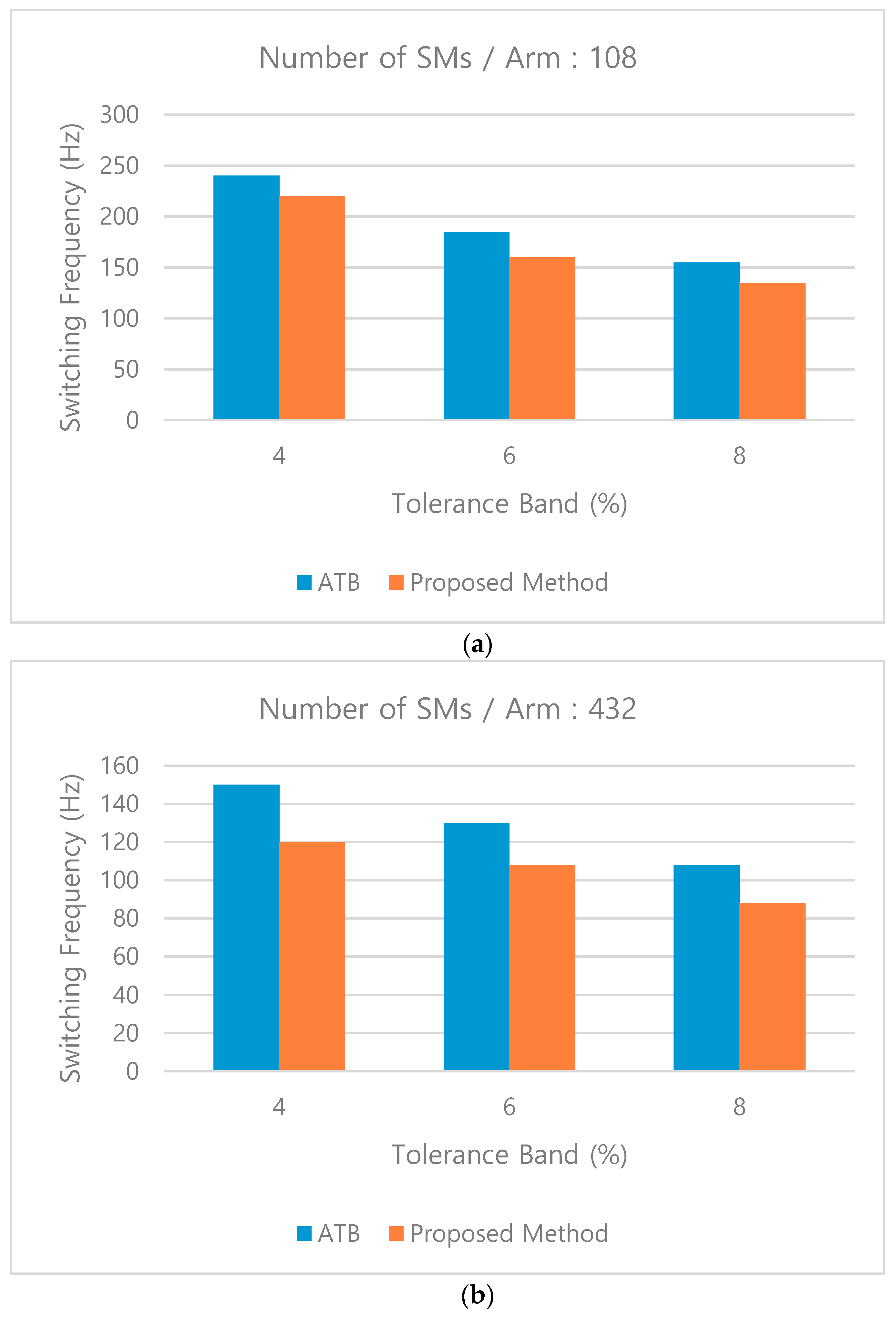
As shown in Figure 21, the proposed method proved to be able to perform better than the conventional method by comparing with the ATB method. Although other specific band generation methods can be applied, the proposed method is applied to band generation using the average value of capacitor voltages, which is one of the tolerance band methods. As shown in Figure 21a, in case of 240 MW-class MMC-HVDC, the proposed method reduces the switching frequency by about 13%, compared to ATB at 4%, 6%, and 8%, of the tolerance band. Likewise, as shown in Figure 21a, in case of 1 GW-class MMC-HVDC, the proposed method reduces the switching frequency by about 20%, compared to ATB at 4%, 6%, and 8%, of the tolerance band. As a result, the proposed method has about 20% better performance than the ATB method, and the larger the number of SMs, the better the effect.
6. Conclusions
This paper provides how to implement the MMC-HVDC HILS system using a RTDS and a physical control system. This HILS system was able to verify the performance of the controller before simulating the actual experiment in the testbed and it is proved that it is a good simulation device to compare characteristics of each algorithm by implementing various submodule capacitor voltage balancing methods. The MMC-HVDC system should focus on the control period and switching frequency as the number of sub-modules (SMs) increases. Using the FPGA’s high-speed operation and parallel processing, it is possible to design high capacity MMC control devices. The proposed capacitor voltage balancing method is performed evenly compared with the conventional method, such as the tolerance band methods, so that the magnitude of the circulating current and the DC-link ripple can be reduced. In addition, as the number of SMs increases, that is, the capacity of MMC increases, the proposed method can obtain a greater effect when the SM capacitor voltages are balancing.
Author Contributions
Conceptualization, J.L. (Junmin Lee) and D.K.; methodology, J.L. (Junmin Lee); software, J.L. (Junmin Lee); validation, J.L. (Junmin Lee), D.K. and J.L. (Jangmyung Lee); formal analysis, J.L. (Junmin Lee), D.K. and J.L. (Jangmyung Lee); investigation, J.L. (Junmin Lee) and D.K.; resources, J.L. (Junmin Lee) and D.K.; data curation, J.L. (Junmin Lee) and D.K.; writing—original draft preparation, J.L. (Junmin Lee); writing—review and editing, J.L. (Junmin Lee); visualization, J.L. (Junmin Lee); supervision, D.K. and J.L. (Jangmyung Lee); project administration, D.K.; funding acquisition, J.L. (Junmin Lee) and D.K.
Funding
This research received no external funding.
Acknowledgments
This research was supported by the Korea Electrotechnology Research Institute (KERI) Primary research program through the National Research Council of Science & Technology (NST) funded by the Ministry of Science and ICT (MSIT) (No. 19-12-N0101-39).
Conflicts of Interest
The authors declare no conflict of interest.
References
- Gemmell, B.; Dorn, J.; Retzmann, D.; Soerangr, D. Prospects of multi-level VSC technologies for power transmission. In Proceedings of the 2008 IEEE/PES Transmission and Distribution Conference and Exposition, Chicago, IL, USA, 21–24 April 2008; pp. 1–16. [Google Scholar]
- Andersen, B.R.; Xu, L.; Wong, K.T.G. Topologies for VSC transmission. Power Eng. J. 2001, 16, 298–304. [Google Scholar]
- Lauss, G.F.; Faruque, M.O.; Schoder, K.; Dufour, C.; Viehweider, A.; Langston, J. Characteristics and Design of Power Hardware-in-the-Loop Simulations for Electrical Power Systems. IEEE Trans. Ind. Electron. 2016, 63, 406–417. [Google Scholar] [CrossRef]
- Huo, Y.; Gruosso, G. Ancillary Service with Grid Connected PV: A Real-Time Hardware-in-the-Loop Approach for Evaluation of Performances. Electronics 2019, 8, 7. [Google Scholar] [CrossRef]
- Liang, T.; Dinavahi, V. Real-Time Device-Level Simulation of MMC-Based MVDC Traction Power System on MPSoC. IEEE Trans. Transp. Electr. 2018, 4, 626–641. [Google Scholar] [CrossRef]
- Ghanbari, N.; Bhattacharya, S. Hardware-In-The-Loop Implementation of a Grid Connected PV System. In Proceedings of the IAS Annual Meeting 2018, Baltimore, MD, USA, 23–27 September 2018. [Google Scholar]
- Majstorovic, D.; Celanovic, I.; Teslic, N.D.; Celanovic, N.; Katic, V.A. Ultralow-latency hardware-in-the-loop platform for rapid validation of power electronics designs. IEEE Trans. Ind. Electron. 2011, 5, 4708–4716. [Google Scholar] [CrossRef]
- Ebe, F.; Idlbi, B.; Stakic, D.E.; Chen, S.; Kondzialka, C.; Casel, M.; Heilscher, G.; Seitl, C.; Bründlinger, R.; Strasser, T.I. Comparison of Power Hardware-in-the-Loop Approaches for the Testing of Smart Grid Controls. Energys 2018, 11, 12. [Google Scholar] [CrossRef]
- Huo, Y.; Gruosso, G. Hardware-in-the-Loop Framework for Validation of Ancillary Service in Microgrids: Feasibility, Problems and Improvement. IEEE Access 2019, 7, 58104–58112. [Google Scholar] [CrossRef]
- Oguma, K.; Akagi, H. Low-Voltage-Ride-Through (LVRT) Control of an HVDC Transmission System Using Two Modular Multilevel DSCC Converters. IEEE Trans. Power Electron. 2017, 32, 5931–5942. [Google Scholar] [CrossRef]
- Ji, S.; Wang, F.; Tolbert, L.M.; Lu, T.; Zhao, Z.; Yu, H. An FPGA-Based Voltage Balancing Control for Multi-HV-IGBTs in Series Connection. IEEE Trans. Ind. Appl. 2018, 54, 4640–4649. [Google Scholar] [CrossRef]
- Beddard, A.; Barnes, M.; Preece, R. Comparison of Detailed Modeling Techniques for MMC Employed on VSC-HVDC Schemes. IEEE Trans. Power Deliv. 2011, 30, 579–589. [Google Scholar] [CrossRef]
- Tang, Y.; Ran, L.; Alatise, O.; Mawby, P. A Model Assisted Testing Scheme for Modular Multilevel Converter. IEEE Trans. Power Electron. 2016, 31, 165–176. [Google Scholar] [CrossRef]
- Tu, Q.; Xu, Z.; Chang, Y.; Guan, L. Suppressing DC Voltage Ripples of MMC-HVDC Under Unbalanced Grid Conditions. IEEE Trans. Power Deliv. 2012, 27, 1332–1338. [Google Scholar] [CrossRef]
- Antonopoulos, A.; Angquist, L.; Nee, H. On dynamics and voltage control of the Modular Multilevel Converter. In Proceedings of the 13th European Conference on Power Electronics and Applications, Barcelona, Spain, 8–10 September 2009. [Google Scholar]
- Tu, Q.; Xu, Z. Impact of Sampling Frequency on Harmonic Distortion for Modular Multilevel Converter. IEEE Trans. Power Deliv. 2011, 26, 298–306. [Google Scholar] [CrossRef]
- Saad, H.; Ould-Bachir, T.; Mahseredjian, J.; Dufour, C.; Dennetière, S.; Nguefeu, S. Real-Time Simulation of MMCs Using CPU and FPGA. IEEE Trans. Power Electron. 2015, 30, 259–267. [Google Scholar] [CrossRef]
- Tu, Q.; Xu, Z.; Xu, L. Reduced Switching-Frequency Modulation and Circulating Current Suppression for Modular Multilevel Converters. IEEE Trans. Power Deliv. 2011, 26, 2009–2017. [Google Scholar]
- Hassanpoor, A.; Ängquist, L.; Norrga, S.; Ilves, K.; Nee, H.P. Tolerance Band Modulation Methods for Modular Multilevel Converters. IEEE Trans. Power Deliv. 2010, 25, 2903–2912. [Google Scholar]
- Tu, Q.; Xu, Z.; Huang, H.; Zhang, J. Parameter Design Principle of the Arm Inductor in Modular Multilevel Converter based HVDC. In Proceedings of the 2010 International Conference on Power System Technology, Hangzhou, China, 24–28 October 2010. [Google Scholar]
- Kontos, E.; Bauer, P. Reactor design for DC fault ride-through in MMC-based multi-terminal HVDC grids. In Proceedings of the 2016 IEEE 2nd Annual Southern Power Electronics Conference (SPEC), Auckland, New Zealand, 5–8 December 2016. [Google Scholar]
- David, J.P.; Bergeron, E. A step towards intelligent translation from high-level design to RTL. In Proceedings of the 4th IEEE International Workshop on System-on-Chip for Real-Time Applications 2004, Banff, AB, Canada, 19–21 July 2004; pp. 183–188. [Google Scholar]
- Umeda, T.; Oya, S. Performance Comparison of Open-Source Parallel Sorting with OpenMP. In Proceedings of the 2015 Third International Symposium on Computing and Networking (CANDAR), Sapporo, Japan, 8–11 December 2011; pp. 334–340. [Google Scholar]
- Ashourloo, M.; Mirzahosseini, R.; Iravani, R. Enhanced Model and Real-Time Simulation Architecture for Modular Multilevel Converter. IEEE Trans. Power Deliv. 2018, 33, 466–476. [Google Scholar] [CrossRef]
- Pereira, H.A.; Cupertino, A.F.; Xavier, L.S.; Sangwongwanich, A.; Mathe, L.; Bongiorno, M.; Teodorescu, R. Capacitor voltage balance performance comparison of MMC-STATCOM using NLC and PS-PWM strategies during negative sequence current injection. In Proceedings of the 2016 18th European Conference on Power Electronics and Applications (EPE’16 ECCE Europe), Karlsruhe, Germany, 5–9 September 2016; pp. 1–9. [Google Scholar]
- Rejas, M.; Mathe, L.; Burlacu, P.D.; Pereira, H.; Sangwongwanich, A.; Bongiorno, M.; Teodorescu, R. Performance comparison of phase shifted PWM and sorting method for modular multilevel converters. In Proceedings of the 2015 17th European Conference on Power Electronics and Applications (EPE’15 ECCE-Europe), Geneva, Switzerland, 8–10 September 2015; pp. 1–10. [Google Scholar]
- Saeedifard, M.; Iravani, R. Dynamic Performance of a Modular Multilevel Back-to-Back HVDC System. IEEE Trans. Power Electron. 2015, 30, 311–326. [Google Scholar]
Figure 1.
Topology of a three-phase grid-connected modular multilevel converter.
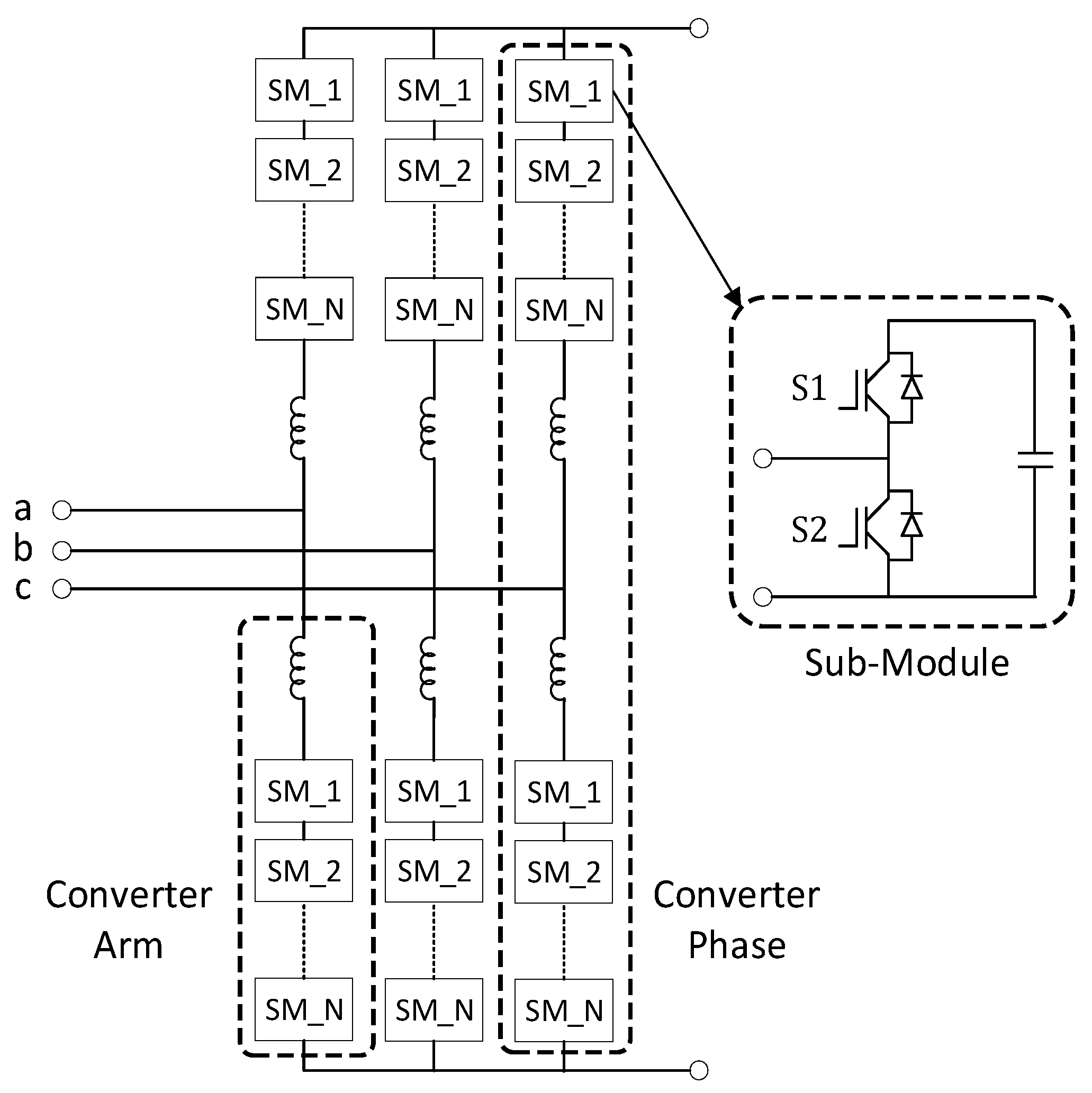
Figure 2.
Equivalent circuit of a three-phase grid-connected modular multilevel converter.
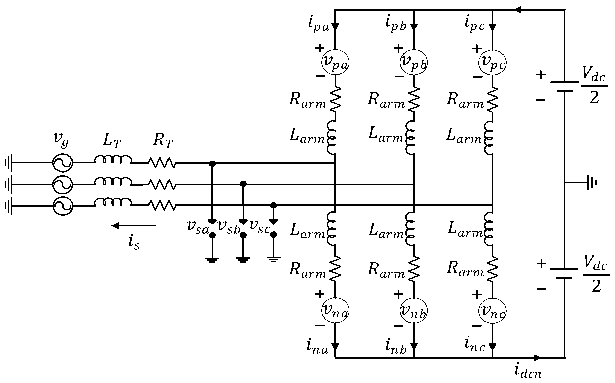
Figure 3.
Block diagram of two control systems for a modular multilevel converter.
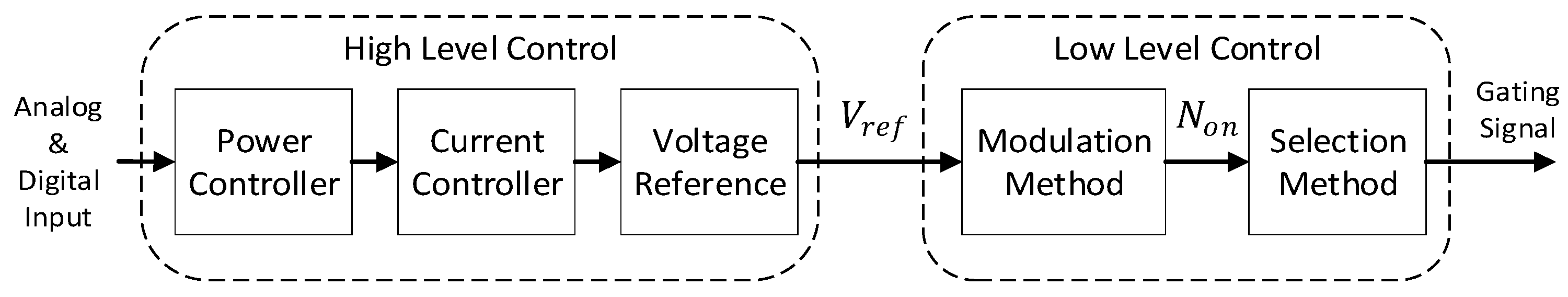
Figure 4.
Flowchart of algorithm operation for physical control system.
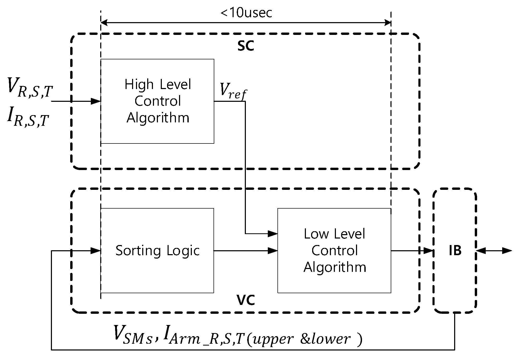
Figure 5.
Hardware in-the-loop simulation (HILS) configuration of modular multilevel converter (MMC)-based high-voltage direct current (HVDC) (MMC-HVDC) transmission using a real-time digital simulator (RTDS) and a physical control system.
Figure 5.
Hardware in-the-loop simulation (HILS) configuration of modular multilevel converter (MMC)-based high-voltage direct current (HVDC) (MMC-HVDC) transmission using a real-time digital simulator (RTDS) and a physical control system.
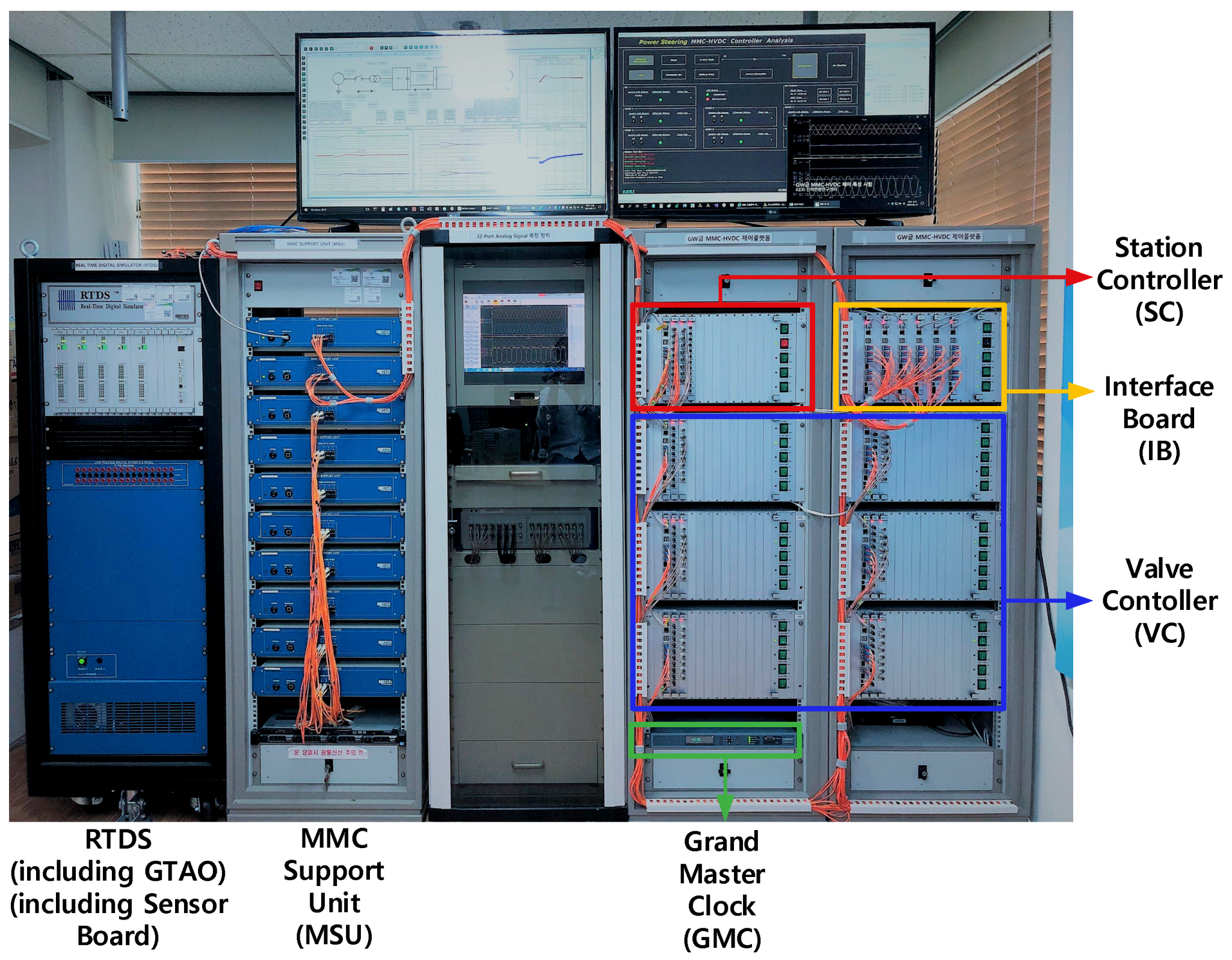
Figure 6.
Block diagram of high-level control methods for a modular multilevel converter.
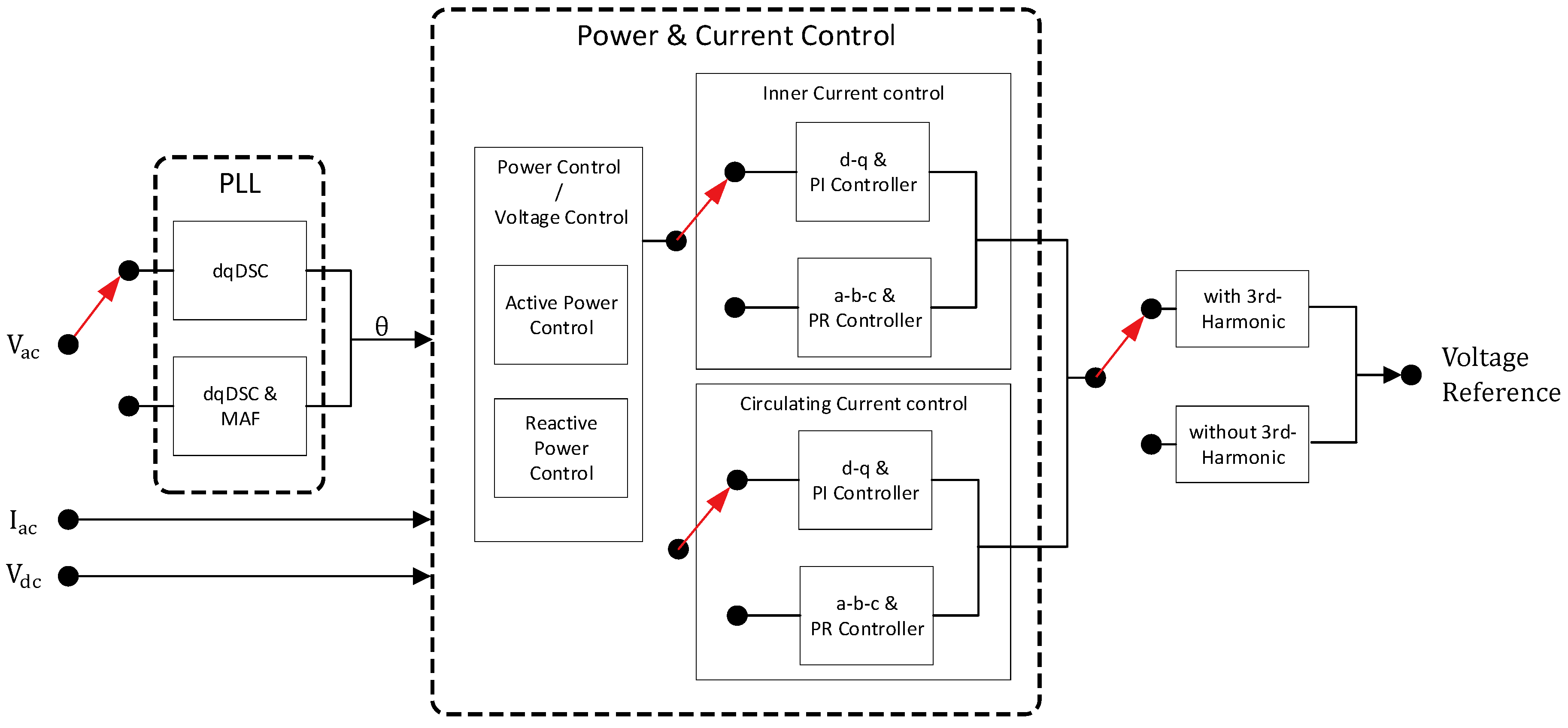
Figure 7.
A block diagram of low-level control methods for a modular multilevel converter.
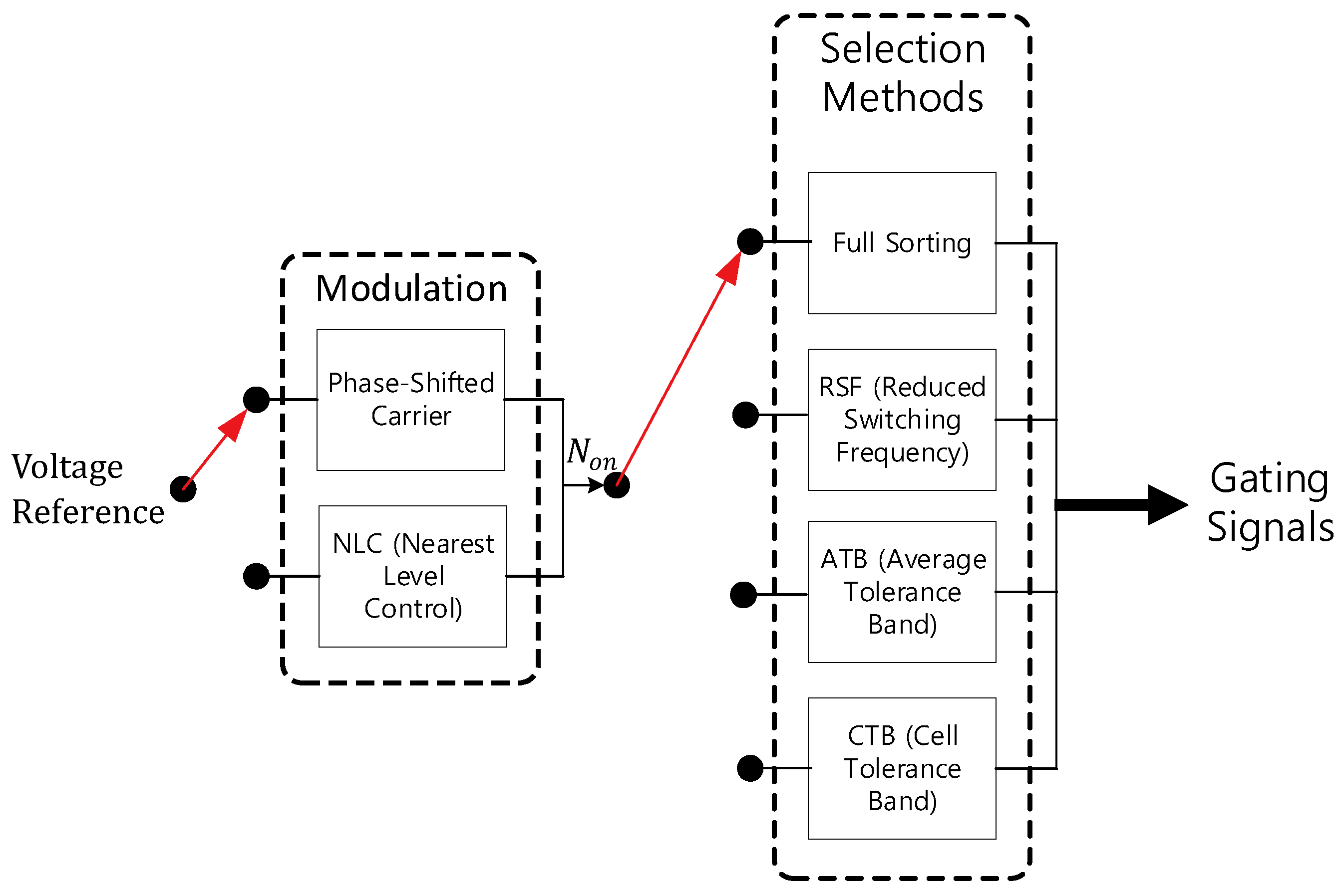
Figure 8.
Even-odd bubble sorting network.
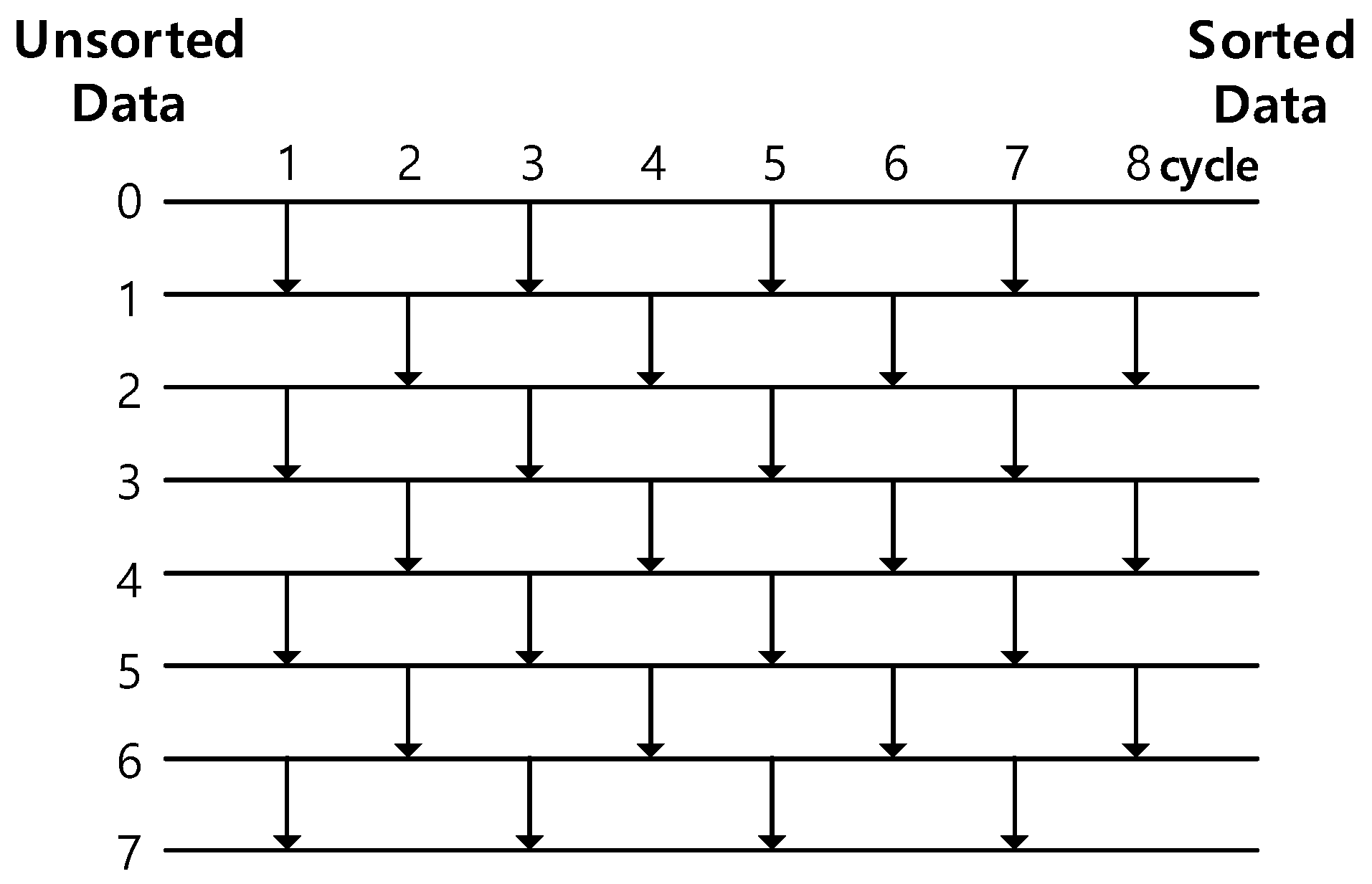
Figure 9.
Logic of high-speed parallel sorting for SM capacitor voltage balancing.
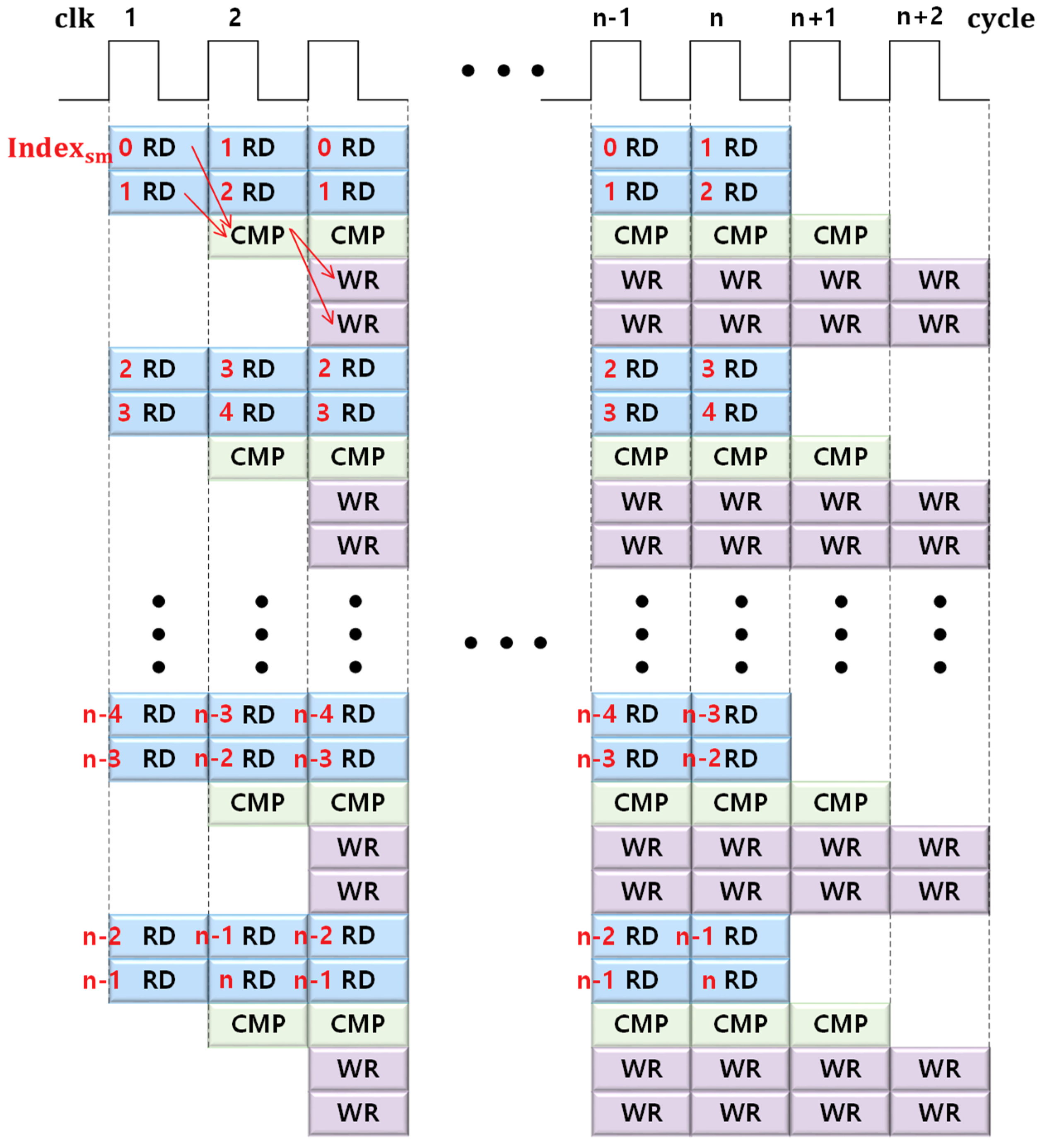
Figure 10.
Diagram of SM capacitor voltage balancing methods for MMC low-level control.
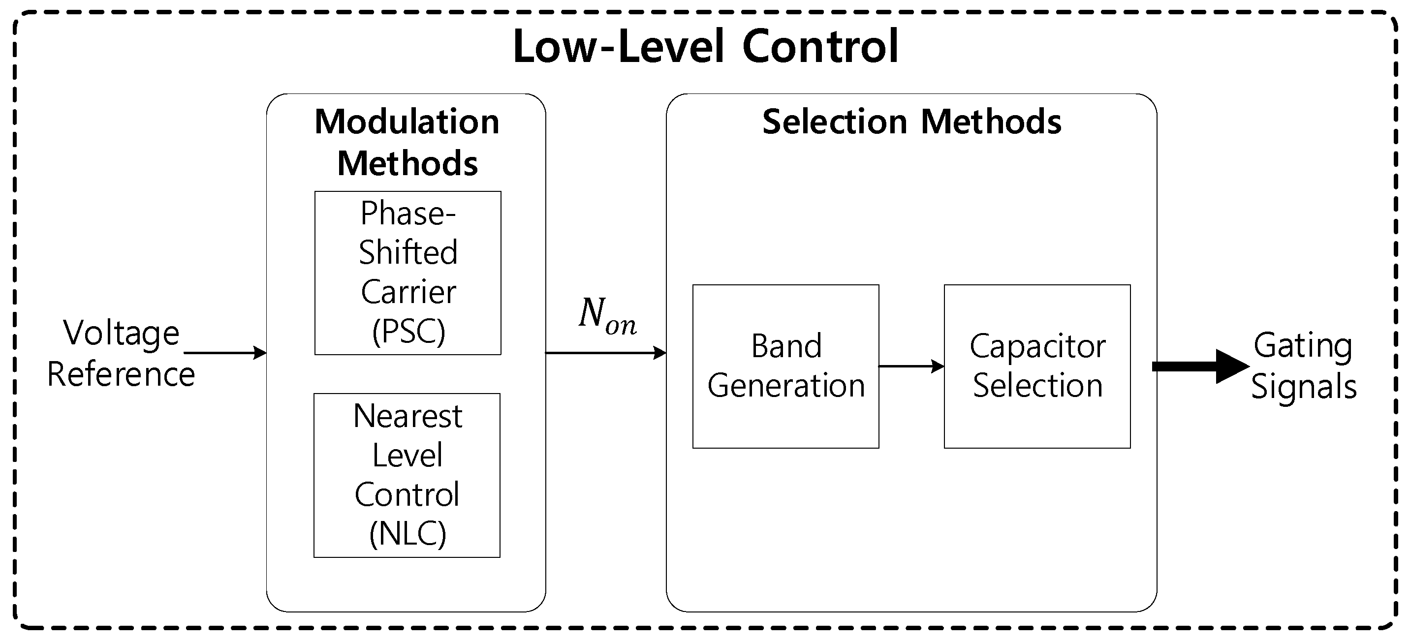
Figure 11.
Proposed SM capacitor voltage balancing method.

Figure 12.
Waveforms of the full sorting method for SM capacitor voltage balancing: (a) Capacitor voltages for 1 GW-class MMC-HVDC transmission; (b) circulating currents for 1 GW-class MMC-HVDC transmission.
Figure 12.
Waveforms of the full sorting method for SM capacitor voltage balancing: (a) Capacitor voltages for 1 GW-class MMC-HVDC transmission; (b) circulating currents for 1 GW-class MMC-HVDC transmission.

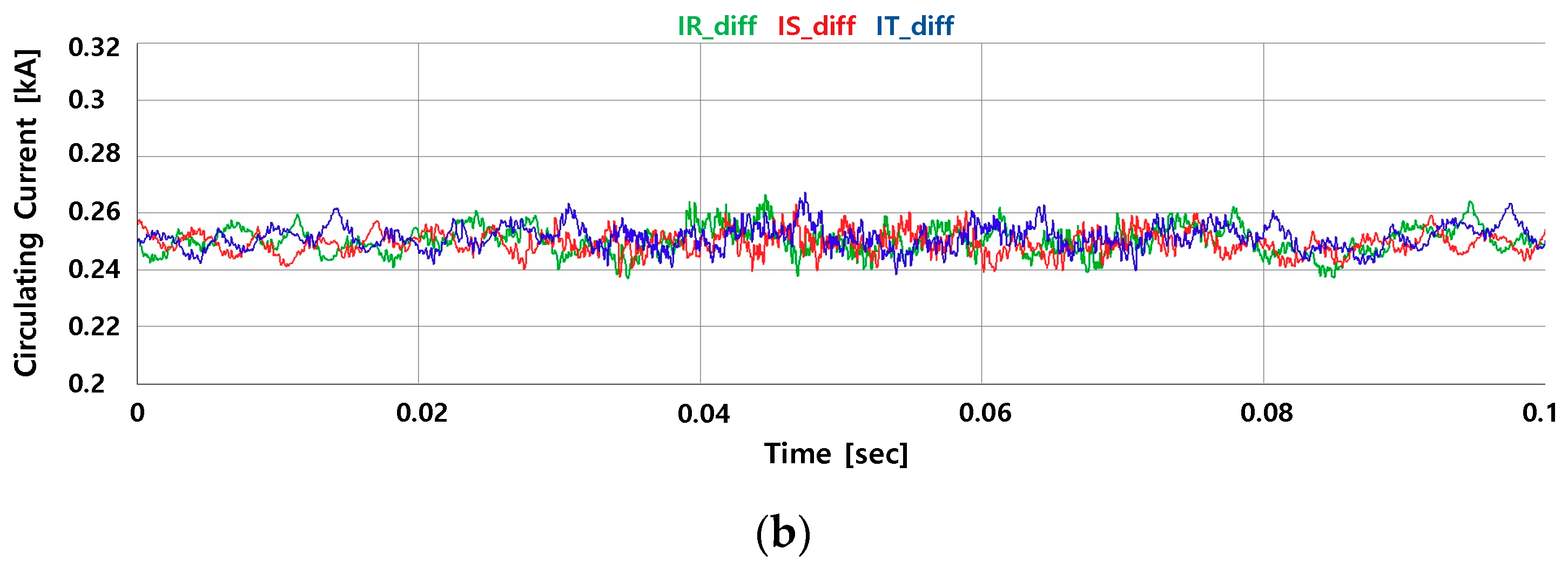
Figure 13.
Waveforms of the reduced switching frequency (RSF) method for SM capacitor voltage balancing: (a) Capacitor voltages for 1 GW-class MMC-HVDC transmission; (b) circulating currents for 1 GW-class MMC-HVDC transmission.
Figure 13.
Waveforms of the reduced switching frequency (RSF) method for SM capacitor voltage balancing: (a) Capacitor voltages for 1 GW-class MMC-HVDC transmission; (b) circulating currents for 1 GW-class MMC-HVDC transmission.
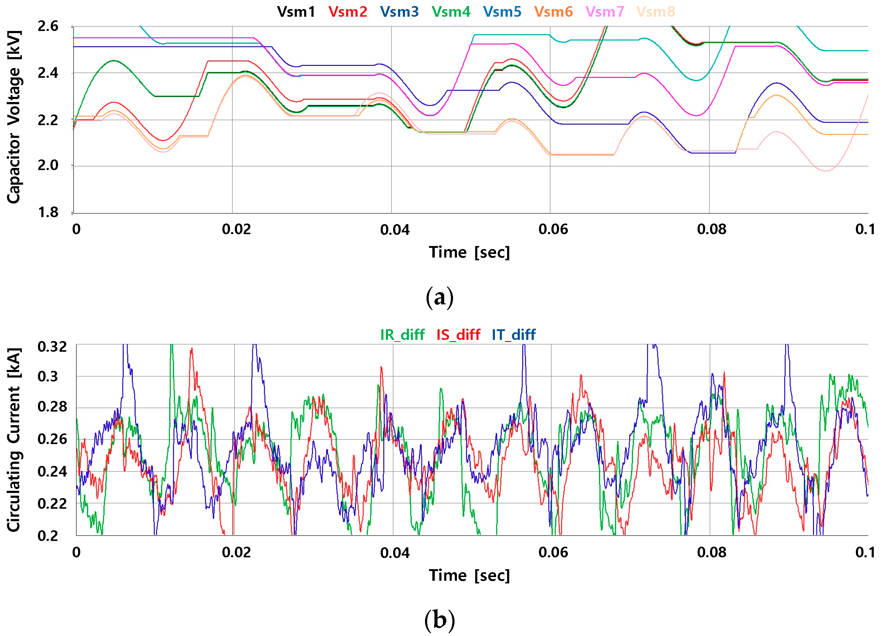
Figure 14.
Waveforms of the cell tolerance band (CTB) method for SM capacitor voltage balancing: (a) Capacitor voltages for 1 GW-class MMC-HVDC transmission; (b) circulating currents for 1 GW-class MMC-HVDC transmission.
Figure 14.
Waveforms of the cell tolerance band (CTB) method for SM capacitor voltage balancing: (a) Capacitor voltages for 1 GW-class MMC-HVDC transmission; (b) circulating currents for 1 GW-class MMC-HVDC transmission.
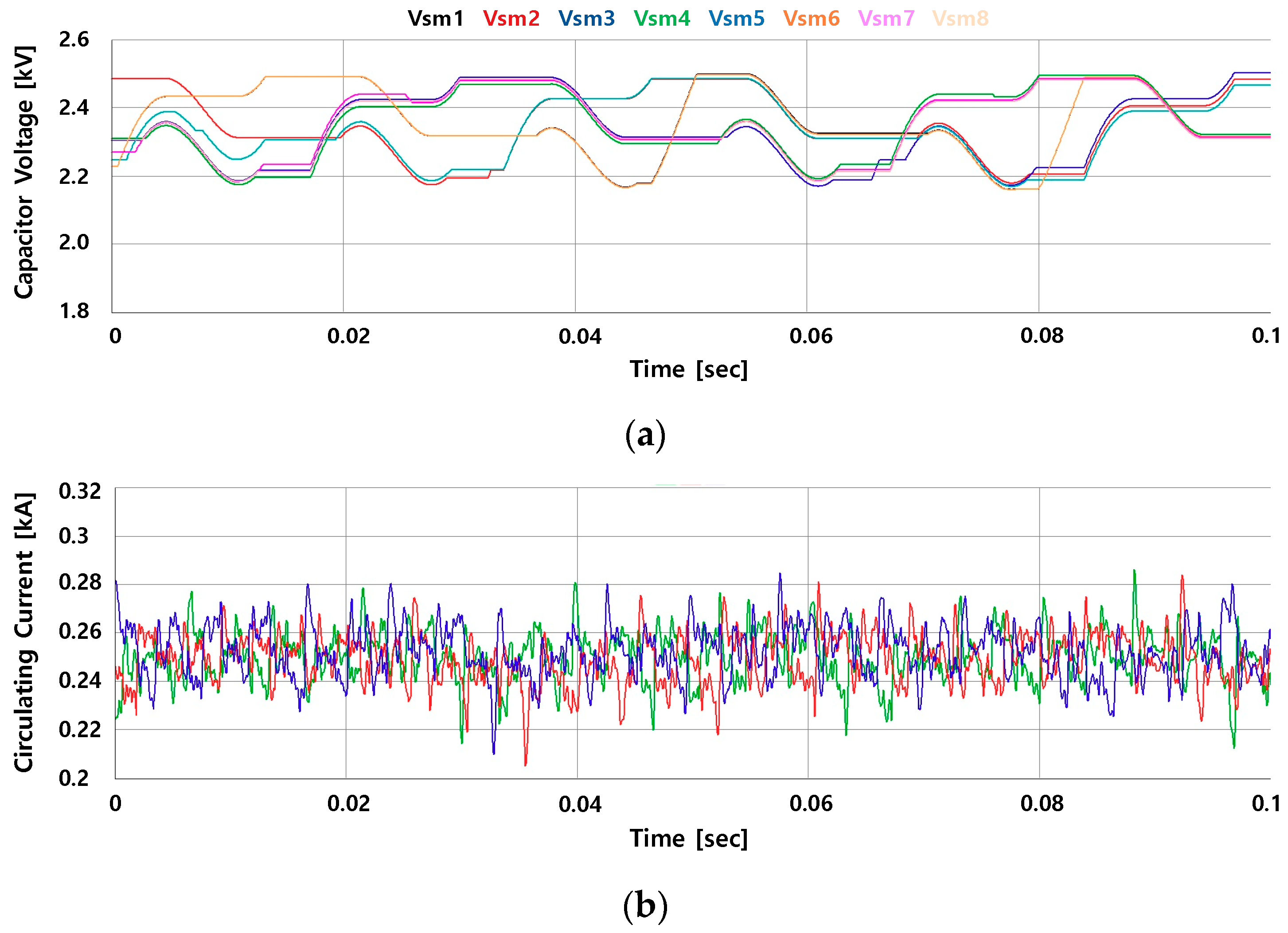
Figure 15.
Waveforms of the average tolerance band (ATB) method for SM capacitor voltage balancing: (a) Capacitor voltages for 1 GW-class MMC-HVDC transmission; (b) circulating currents for 1 GW-class MMC-HVDC transmission.
Figure 15.
Waveforms of the average tolerance band (ATB) method for SM capacitor voltage balancing: (a) Capacitor voltages for 1 GW-class MMC-HVDC transmission; (b) circulating currents for 1 GW-class MMC-HVDC transmission.
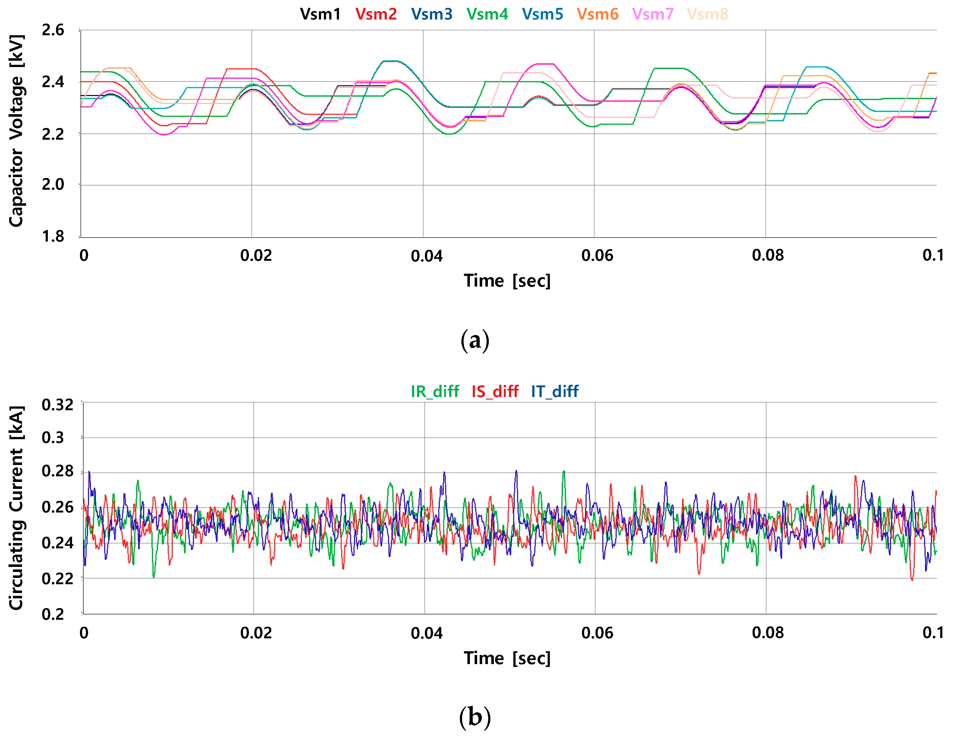
Figure 16.
Analysis of capacitor voltages for SM capacitor voltage balancing methods: (a) ATB method for 1 GW-class MMC-HVDC transmission; (b) proposed method for 1 GW-class MMC-HVDC transmission.
Figure 16.
Analysis of capacitor voltages for SM capacitor voltage balancing methods: (a) ATB method for 1 GW-class MMC-HVDC transmission; (b) proposed method for 1 GW-class MMC-HVDC transmission.
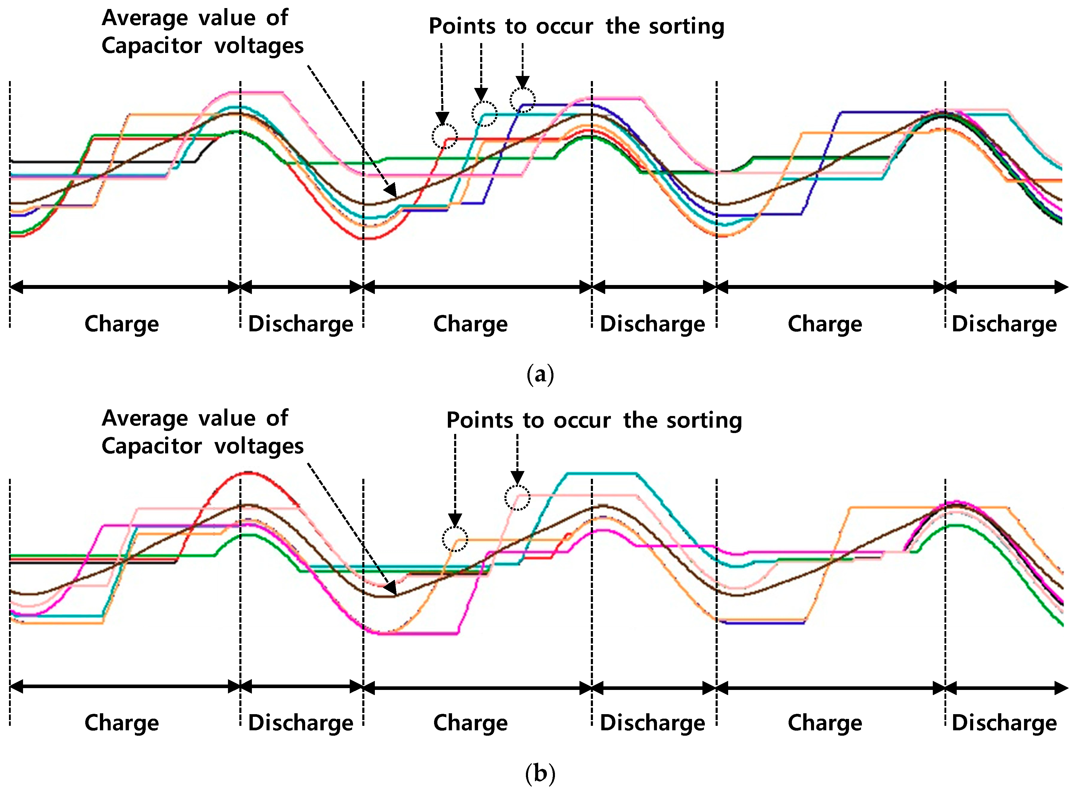
Figure 17.
Waveforms of SM capacitor voltages compared with the ATB method and proposed method for 240 MW class MMC-HVDC transmission: (a) SM capacitor voltages of the ATB method for a 4% tolerance band; (b) SM capacitor voltages of the ATB method for a 6% tolerance band; (c) SM capacitor voltages of the ATB method for an 8% tolerance band; (d) SM capacitor voltages of the proposed method for a 4% tolerance band; (e) SM capacitor voltages of the proposed method for a 6% tolerance band; (f) SM capacitor voltages of the proposed method for an 8% tolerance band.


Figure 18.
Waveforms of circulating currents to compare with the ATB method and proposed method for a 240 MW-class MMC-HVDC transmission: (a) Circulating currents of the ATB method for a 4% tolerance band; (b) circulating currents of the ATB method for a 6% tolerance band; (c) circulating currents of the ATB method for an 8% tolerance band; (d) circulating currents of the proposed method for a 4% tolerance band; (e) circulating currents of the proposed method for a 6% tolerance band; (f) circulating currents of the proposed method for an 8% tolerance band.
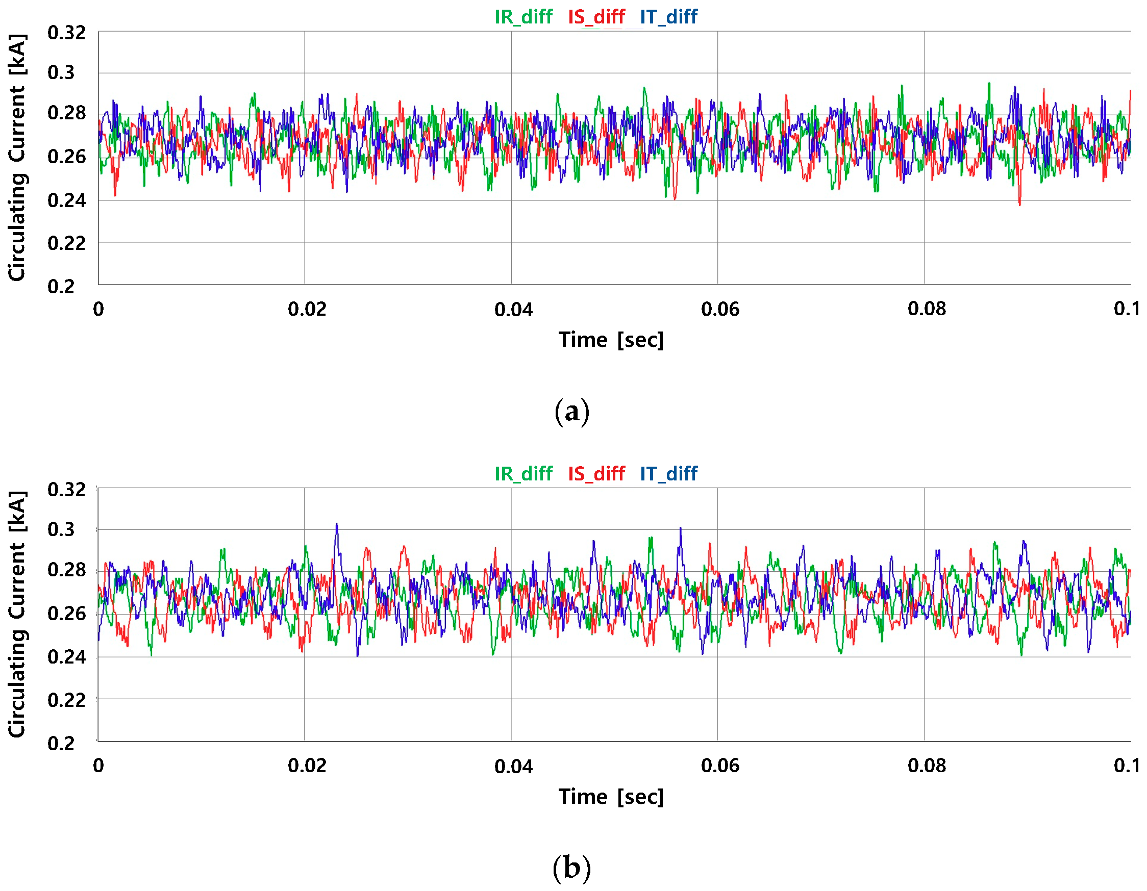
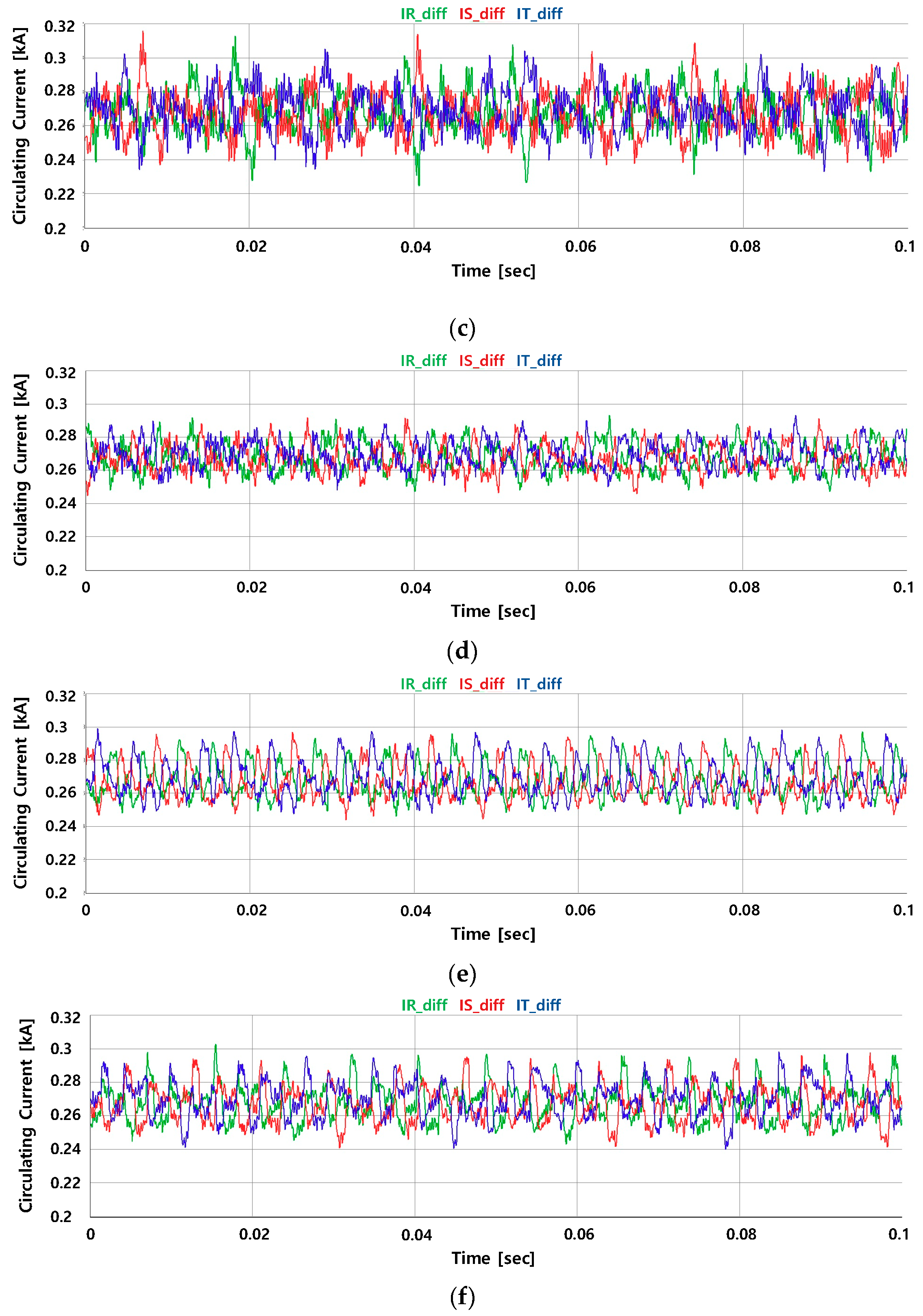
Figure 19.
Waveforms of SM capacitor voltages to compare with the ATB method and proposed method for 1 GW-class MMC-HVDC transmission: (a) SM capacitor voltages of the ATB method for a 4% tolerance band; (b) SM capacitor voltages of the ATB method for a 6% tolerance band; (c) SM capacitor voltages of the ATB method for an 8% tolerance band; (d) SM capacitor voltages of the proposed method for a 4% tolerance band; (e) SM capacitor voltages of the proposed method for a 6% tolerance band; (f) SM capacitor voltages of the proposed method for an 8% tolerance band.
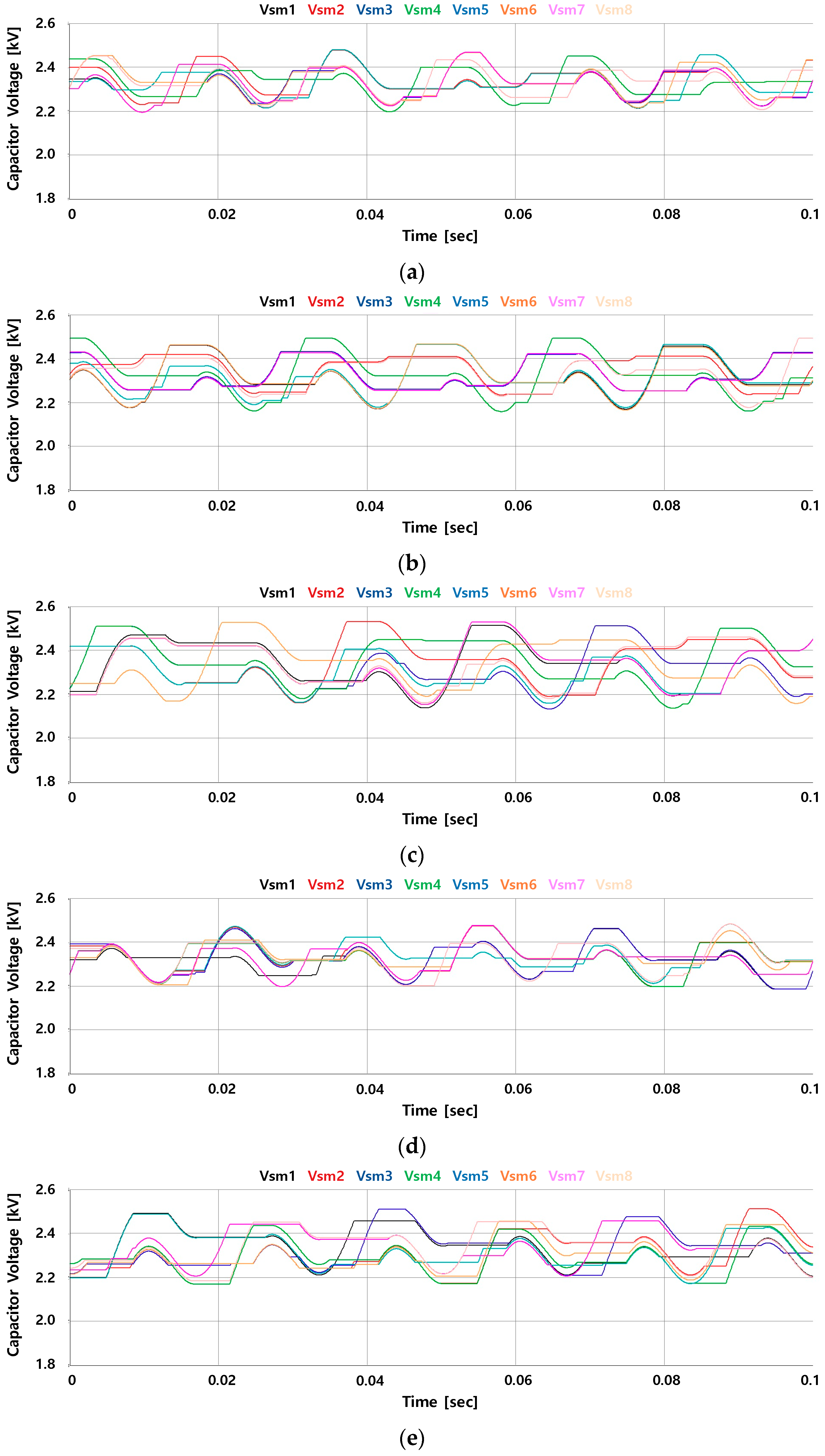
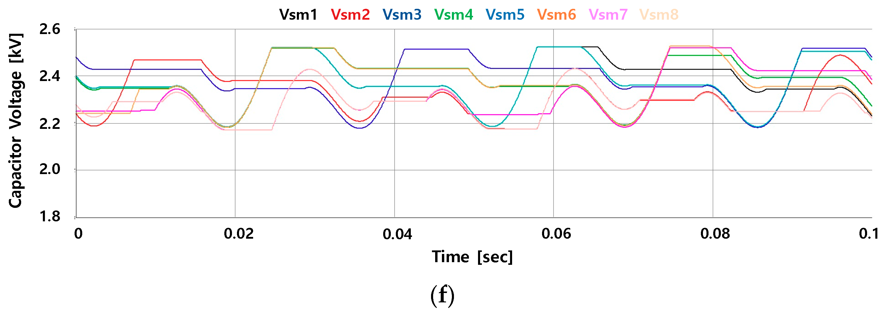
Figure 20.
Waveforms of circulating currents to compare with the ATB method and proposed method for 1 GW-class MMC-HVDC transmission: (a) Circulating currents of the ATB method for a 4% tolerance band; (b) circulating currents of the ATB method for a 6% tolerance band; (c) circulating currents of the ATB method for an 8% tolerance band; (d) circulating currents of the proposed method for a 4% tolerance band; (e) circulating currents of the proposed method for a 6% tolerance band; (f) circulating currents of proposed method for an 8% tolerance band.
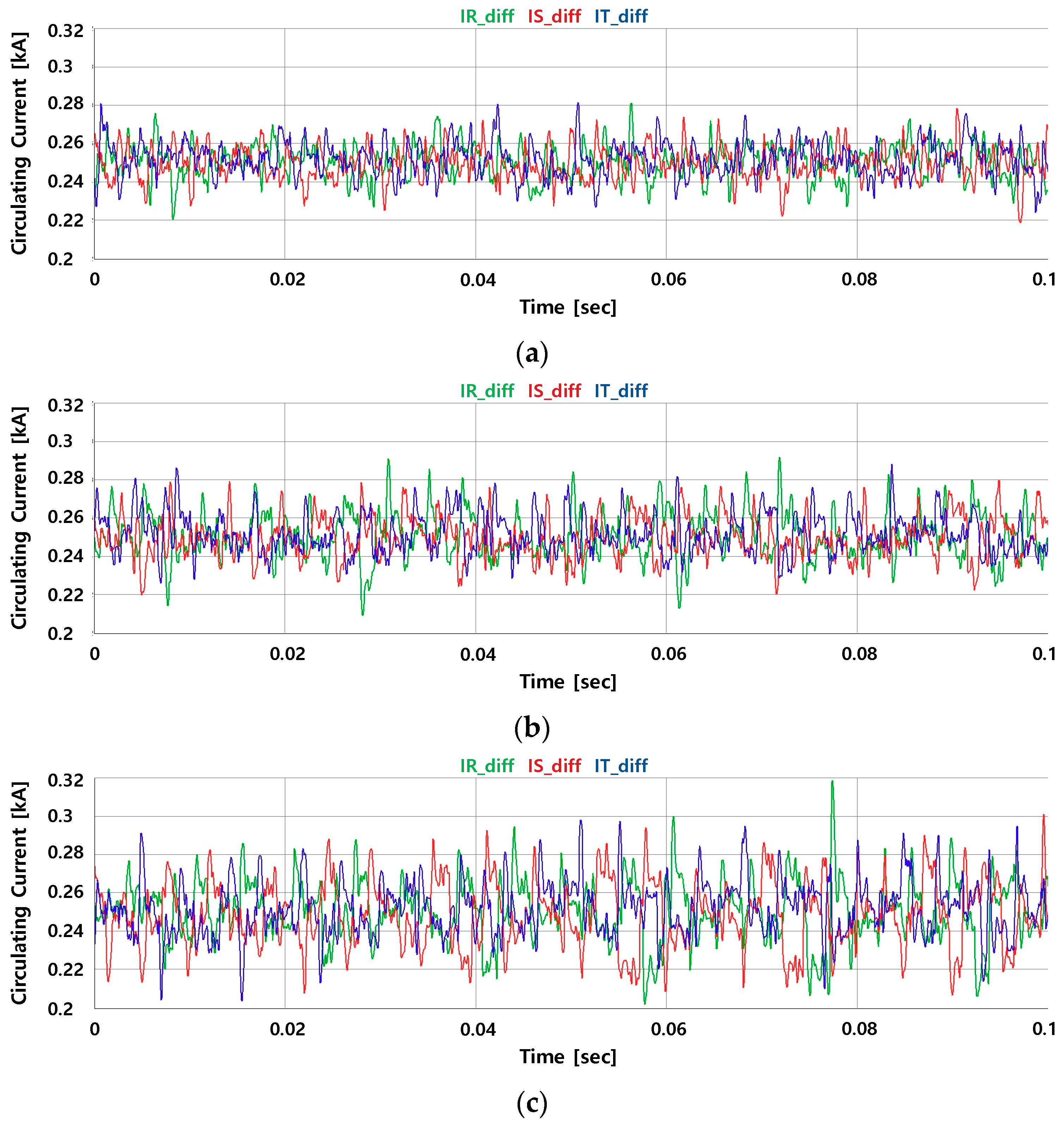
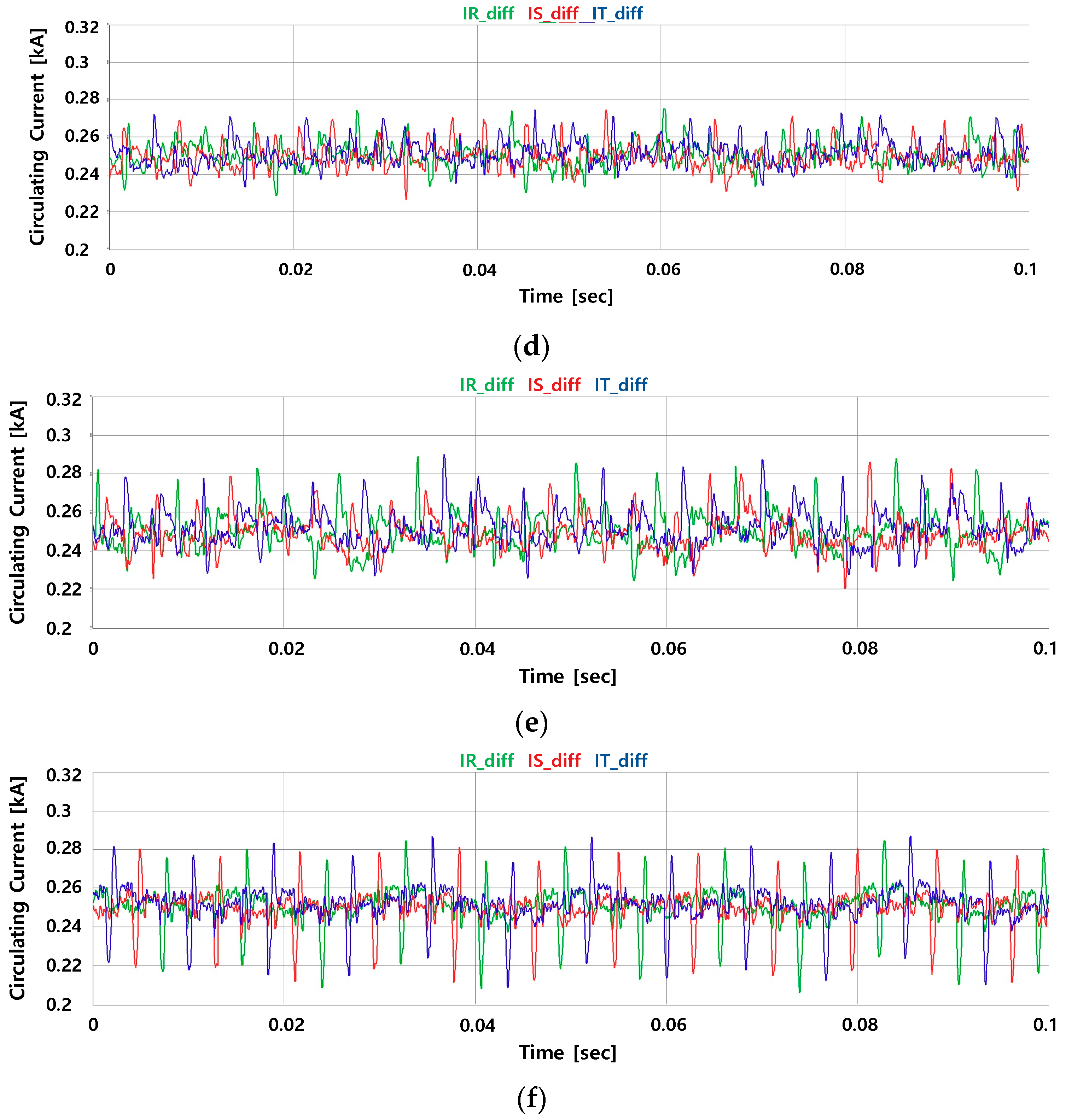
Figure 21.
Compared chart of switching frequency between the ATB method and proposed method: (a) Switching frequency for 240 MW-class MMC-HVDC transmission; (b) switching frequency 1 GW-class MMC-HVDC transmission.
Figure 21.
Compared chart of switching frequency between the ATB method and proposed method: (a) Switching frequency for 240 MW-class MMC-HVDC transmission; (b) switching frequency 1 GW-class MMC-HVDC transmission.

Table 1.
240 MW MMC-HVDC specification.
| Quantity | Value of Unit |
|---|---|
| Max Active Power | 240 MW |
| Rated DC Link Voltage | ±120 kV |
| Rated DC Current | 1000 A |
| Primary Voltage of Transformer | 154 kV |
| Secondary Voltage of Transformer | 118 kV |
| Number of SMs per Arm | 100 (+8) |
| Inductance per Arm Reactor | 20 mH |
| Capacity per SM | 6 uF |
| Control Cycle | 10 usec |
Table 2.
1 GW MMC-HVDC specification.
| Quantity | Value of Unit |
|---|---|
| Max Active Power | 1000 MW |
| Rated DC Link Voltage | ±500 kV |
| Rated DC Current | 1000 A |
| Primary Voltage of Transformer | 528 kV |
| Secondary Voltage of Transformer | 460 kV |
| Number of SMs per Arm | 400 (+32) |
| Inductance per Arm Reactor | 50 mH |
| Capacity per SM | 10 mF |
| Control Cycle | 10 usec |
© 2019 by the authors. Licensee MDPI, Basel, Switzerland. This article is an open access article distributed under the terms and conditions of the Creative Commons Attribution (CC BY) license (http://creativecommons.org/licenses/by/4.0/).
Share and Cite
MDPI and ACS Style
Lee, J.; Kang, D.; Lee, J. A Study on the Improved Capacitor Voltage Balancing Method for Modular Multilevel Converter Based on Hardware-In-the-Loop Simulation. Electronics 2019, 8, 1070. https://doi.org/10.3390/electronics8101070
AMA Style
Lee J, Kang D, Lee J. A Study on the Improved Capacitor Voltage Balancing Method for Modular Multilevel Converter Based on Hardware-In-the-Loop Simulation. Electronics. 2019; 8(10):1070. https://doi.org/10.3390/electronics8101070
Chicago/Turabian StyleLee, Junmin, Daewook Kang, and Jangmyung Lee. 2019. "A Study on the Improved Capacitor Voltage Balancing Method for Modular Multilevel Converter Based on Hardware-In-the-Loop Simulation" Electronics 8, no. 10: 1070. https://doi.org/10.3390/electronics8101070
Note that from the first issue of 2016, this journal uses article numbers instead of page numbers. See further details here.