Improved ISRJ-Based Radar Target Echo Cancellation Using Frequency Shifting Modulation


State Key Laboratory of Complex Electromagnetic Environment Effects on Electronics and Information System, National University of Defense Technology, Changsha 410073, China
*
Authors to whom correspondence should be addressed.
Electronics 2019, 8(1), 46; https://doi.org/10.3390/electronics8010046
Submission received: 10 December 2018
/
Revised: 25 December 2018
/
Accepted: 28 December 2018
/
Published: 1 January 2019
(This article belongs to the Special Issue Advanced Technology Related to Radar Signal, Imaging, and Radar Cross-Section Measurement)
Abstract
:Target echo cancellation is an ingenious method that protects the target of interest (TOI) from being detected by radar. Interrupted-sampling repeater jamming (ISRJ) is a novel deception jamming method for linear frequency modulation (LFM) radar countermeasures, which has been applied in target echo cancellation recently. Compared with the conventional cancellation method, not only can the target echo be successfully cancelled at radar receiver, but a train of false targets is also produced and forms deception jamming by applying the ISRJ technique. In this paper, an improved radar target echo cancellation method based on ISRJ is proposed that utilizes an extra frequency shifting modulation on the intercepted LFM radar signal. The jammer power is more efficiently utilized by the proposed method. Moreover, more flexible multi-false-target deception jamming can be obtained by adjusting the interrupted sampling frequency. The real target remains effectively protected by the false preceding target in the presence of amplitude mismatch of cancellation signal and target echo. Numerical simulations and measured data experiments are conducted to demonstrate the effectiveness of the proposed method.
1. Introduction
Radar plays an important role in both civil and military fields as its all-weather and day-night capacities superior to the optical sensors [1,2,3,4]. To protect the targets of interest (TOI) from being detected by the radar, radar jamming techniques have been widely studied over the past few decades, including blanket jamming and deception jamming. Interrupted-sampling repeater jamming (ISRJ) is a novel radar deception jamming technique proposed in 2006 [5,6]. By sampling and repeating the radar signal at sub-Nyquist rates, a train of false targets is produced after radar matched filtering (MF) processing. Thus ISRJ is widely applied in radar jamming including synthetic aperture radar (SAR) [7,8,9,10] and inverse synthetic aperture radar (ISAR) [11,12]. On the other hand, the anti-ISRJ technique also develops rapidly in the past decades [13].
Radar target echo cancellation is an ingenious jamming method that cancels the target echo at the radar receiver [14,15,16,17,18,19,20,21,22]. The core idea lies in transmitting a synthesized replica of the target echo except for its being out of phase to the radar by an active source. For linear frequency modulation (LFM) pulse compression radar, ISRJ can produce a train of false targets with controllable amplitudes and phases. Based on this phenomenon, a radar target echo cancellation method using self-protection ISRJ is proposed [23,24]. By designing the interrupted sampling frequency, the repeater time-delay and the jammer power, the ISRJ signal not only ideally cancels radar target echo with −1 order false target, but also produces a train of false targets. Thus a better cancellation performance is obtained compared with the conventional cancellation methods due to the multi-false-target deception jamming. In our previous work, the cancellation method based on nonperiodic ISRJ has been further proposed, considering the unavoidable amplitude mismatch of the cancellation signal and the target echo [25]. However, on the one hand, the energy of −1 order false target is lower than 0 order false target in ISRJ. Hence a relatively large transmitting power is needed, which may lead to hostile anti-radiation weapons attack. If 0 order false target can be used to cancel the target echo, the jammer power can be reduced efficiently. This protects the jammer equipment effectively. On the other hand, interrupted sampling frequency should be precisely designed according to radar signal parameters as noted in [23], so the position of the false targets produced by ISRJ remains fixed in the radar MF output, which makes it easier to be countered [26].
Range-Doppler coupling is a unique property for LFM signal, which causes the peak of the compressed pulse to shift in time by an amount proportional to the Doppler frequency [27]. By utilizing this property, some effective methods against LFM radar such as frequency-shifting deception jamming have been proposed [28,29]. Inspired by this, the main contribution of this paper is to propose an ISRJ-based radar target echo cancellation method with an extra frequency-shifting modulation. By the frequency shifting modulation on the ISRJ signal, the radar target echo can be cancelled by the 0 order false target. Thus the jammer power is more efficiently utilized, which will also protect the jammer due to the smaller radiation energy. Moreover, the interrupted sampling frequency can be flexibly adjusted to change the position of false targets in the proposed method, thus better deception jamming is performed. Last but not least, the preceded −1 order false target will shield the TOI more effectively in the presence of amplitude mismatch of the cancellation signal and the target echo.
The remainder of the paper is organized as follows. In Section 2, the existing radar target echo cancellation method based on ISRJ is reviewed, and the shortage is analyzed. In Section 3, the improved cancellation method is proposed. In Section 4, numerical simulations and measured SAR data experiments are conducted to illustrate the validity of the proposed method. Finally, conclusions are drawn in Section 5.
2. Review of Radar Target Echo Cancellation Based on ISRJ
2.1. Amplitude and Phase Characteristics of the ISRJ Signal
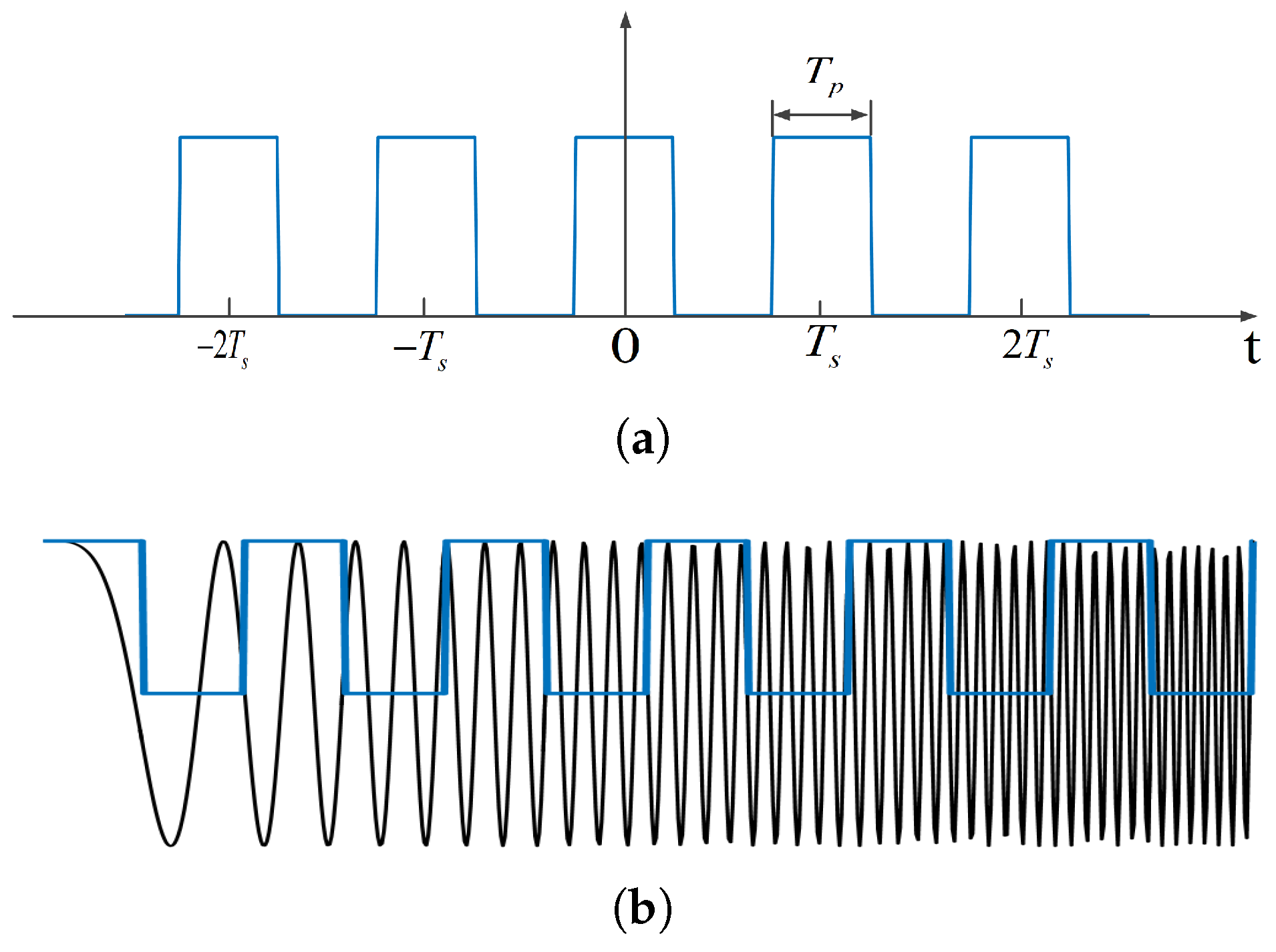
As shown in Figure 1a, assume the interrupted sampling function is a rectangular envelope pulse train denoted as , then
where t denotes the time variable, is the pulse width, is the pulse repetition interval (PRI), is the impulse function, n is the pulse number, ⊗ represents the convolution operation, and . The sampling duty ratio is defined as .
Via Fourier transform, the spectrum of is given as
where , and represents the interrupted sampling frequency.
The radar transmits LFM pulse signal, denoted as
where T is the pulse width, k is the chirp rate and the bandwidth is .
Figure 1b presents the interrupted sampling processing of LFM signal, then the ISRJ signal can be expressed as
As demonstrated in [5], the MF output of ISRJ signal at radar receiver is formed by a train of false targets, given by
where
is the amplitude coefficient of n order false target.
represents the pulse compression output of n order false target.
From Equation (7), the peak of n order false target lies in
The phase of n order false target is
2.2. Target Echo Cancellation Using the ISRJ Signal
For radar target echo cancellation, three conditions should be satisfied including range synchronization, phase coherent and amplitude match. The phase of the radar target echo consists of two components including the propagation phase and the signature of the radar target itself. In self-protection jamming, the target and jammer echoes travel the same distance to the radar, therefore the propagation phase difference is zero. On the other hand, it is assumed, for simplicity, that the target cross-section amplitude equals 1 and the phase equals zero.
For self-protection jamming, the 0 order target lags behind the target echo due to the unavoidable repeater time-delay. Thus parameters of −1 order false target are designed to cancel the target echo [23].
The repeater time-delay satisfies
to guarantee the MF output of the −1 order false target synchronizes with the target echo in time domain.
The interrupted sampling frequency satisfies
to guarantee , which makes the phase of −1 order false target opposites the phase of the real target.
The amplitude modulation coefficient of the jammer satisfies
to guarantee the amplitudes of two echoes equal.
Further, the radiant power of the jammer should satisfy
where P is the peak power of radar, is the receiving antenna gain, is the target RCS, and R is the distance between the jammer and radar.
When Equations (10)–(12) are satisfied, ideal target echo cancellation can be realized in radar receiver. Thus the amplitude and phase modulation of the ISRJ signal is subtly utilized to cancel the target echo by parameter designs.
As analyzed above, the −1 order false target of ISRJ signal is used as the cancellation source, not the 0 order false target which has the strongest amplitude response. It is because the 0 order false target lags behind the real target echo due to the repeater time-delay of self-protection ISRJ. Besides, Equation (9) indicates that the phase of 0 order target is 0, equal to the phase of real target, which may strengthen the real target echo at radar receiver on the contrary. It may lead to hostile anti-radiation weapons attack due to the larger tranmitting power for the existing method. If the 0 order false target can be utilized as the cancellation source by some special modulations, the required jammer power will reduce comparatively. Besides, interrupted sampling frequency must be accurately set by Equation (11). Hence the false target will locate at the fixed position in radar MF output according to Equation (8), which greatly affects the jamming performance.
3. Improved ISRJ-Based Cancellation Method Using Frequency Shifting Modulation
In this section, an improved radar target echo cancellation method using ISRJ is proposed to overcome the shortage of the existing method proposed in Section 2.
As known, the LFM waveform exhibits range-Doppler coupling which causes the peak of the compressed pulse to shift in time by an amount proportional to the Doppler frequency. In particular, the peak occurs earlier in time for a positive LFM slope, compared with the peak response for a stationary target [27]. Inspired by this unique property, a frequency shift can be added to the ISRJ signal to make the 0 order false target synchronize with the real target echo in time domain.
After adding frequency shift, the ISRJ signal can be expressed as
Let be the complete LFM signal after adding frequency shift. The MF output at radar receiver is
Similar to Equations (5) and (15), the MF output of ISRJ signal with frequency shift will be
where is the amplitude coefficient given by Equation (6).
represents the pulse compression output of the n order false target.
According to Equation (17), after frequency modulation, the peak of the n order false target locates at
The phase is
From Equations (18) and (19), both the position and phase of 0 order false target are modulated by the frequency shift. Then the 0 order false target can be utilized to cancel the real target echo. Similarly, three conditions proposed in Section 2 must be satisfied to realize the cancellation.
To guarantee the phase of 0 order false target opposites the phase of the real target, , where m is an integer. Then the frequency shift should satisfy
To guarantee the range synchronization in time domain, the repeater time-delay should satisfy
Assume that the minimum required analyzing time for the canceller is . Obviously should be no smaller than , then
The minimum m is , then , . It is necessary to point out that when the required processing time is larger than the time-delay determined by Equation (10) for the method proposed in Section 2, the echo cancellation will fail. Hence the improved method is more robust from this point of view.
Finally, the required jammer power is calculated. Due to the utilization of 0 order false target, the amplitude modulation coefficient changes to
Compared with the method proposed in Section 2, the radiant power of the jammer will be
From Equation (24), by joint frequency shift and repeater time-delay modulation given by Equations (20) and (21) respectively, the required jammer power reduces to times compared with that of the method proposed in Section 2. Besides, the interrupted sampling frequency is not necessary to be designed particularly. It means that the position of false targets can be flexibly designed by adjusting the interrupted sampling frequency to accord with the demands of electronic countermeasures (ECM). Thus more effective jamming performance can be obtained. Since the cancellation signal is transmitted back to the radar along with the target echo, it is effective against both real-time processing radars and off-line processing radars such as SAR.
However, it is necessary to point out that the tramsmitting power given by Equation (24) is difficult to precisely set due to the unavoidable parameter estimation error. Then the amplitude match of the cancellation signal and target echo cannot be guaranteed. In this case, the target echo cannot be completely erased out at the radar receiver. That is exactly the reason why the nonperiodic interrupted sampling modulation is adopted to protect the target residual with the continuous jamming strip in [25]. In this paper, the false targets generated by the periodic ISRJ are expected to accomplish the target protection. Hence the acceptable intensity of the effective echo cancellation should be analyzed. Since the false targets are expected to protect the target residual, it is reasonable to define that the amplitude of the false target should be larger than that of the suppressed real target for effective cancellation. Hence to achieve the acceptable suppression level, we have
where is the amplitude of the 1 order false target, is the amplitude of the cancellation signal, and is the amplitude of the target echo. According to the interrupted sampling theory, the amplitude of the 1 order false target and the 0 order false target can be given by
Substitute (26) into (25), then
Define the amplitude mismatch degree as
The amplitude mismatch includes two cases, one is the amplitude of the cancellation signal is larger than that of the target echo e.g., , the other is the opposite. Here the former case is mainly discussed. Then the mismatch degree should satisfy
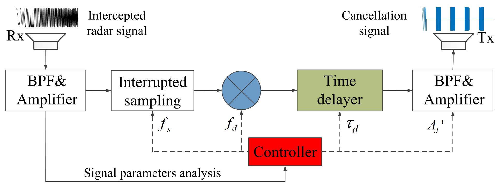
The block diagram of the canceller can be concluded in Figure 2.
As shown in Figure 2, the block diagram of the canceller is similar to that proposed in [25]. The main difference is the interrupted sampling modulation here is periodic. Then the multi-false- target deception jamming is obtained by the proposed method instead of the blanket jamming in [25]. The unavoidable limitations of the canceller are the signal parameters should be precisely measured similar to some other types of deception jammings such as the frequency shifting jamming. The processing procedure can be listed as follows.
Step 1: Intercept the radar signal and analyze signal parameters including chirp rate k, pulse width T.
Step 2: Execute interrupted sampling processing of the intercepted signal with sampling frequency and sampling pulse width , then modulate the cancellation signal by frequency shift and time-delay given by Equations (20) and (21) respectively.
Step 3: Calculate the transmitting power given by Equation (24), then retransmit the cancellation signal to radar.
4. Simulation Results and Analysis
In this section, the performance of the proposed method is analyzed by simulations. For convenience, the existing method proposed in [23] is named as Method 1, and our improved method proposed in Section 3 is named as Method 2.
4.1. Comparison of Required Jammer Power
Firstly, the required jammer power of two methods is compared. The main parameters are listed in Table 1.
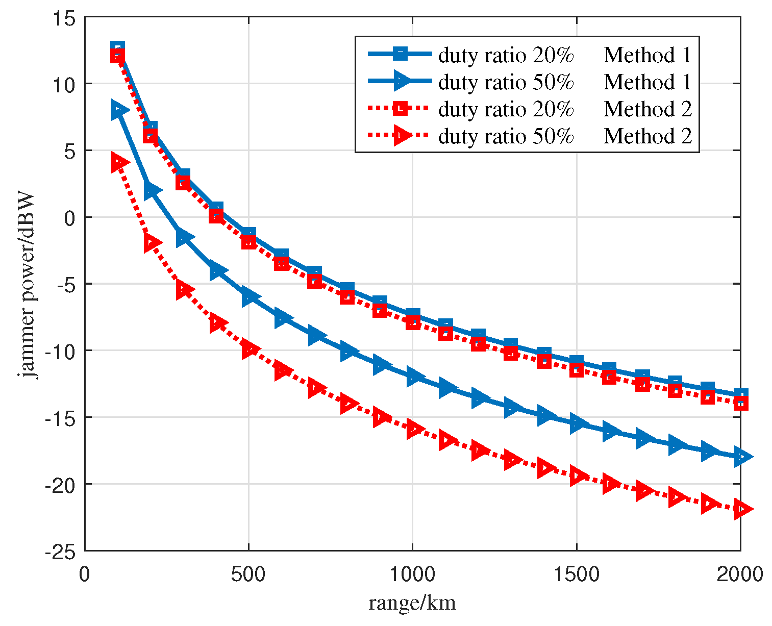
The required jammer power of Method 1 and the proposed Method 2 can be calculated according to Equations (13) and (24) respectively. Figure 3 presents the comparison result of the required jammer power, where the sampling duty ratio of the ISRJ is set as 20% and 50% respectively.
As shown in Figure 3, the required jammer power of Method 2 is lower than that of Method 1 when the duty ratio is equal, and the reduction is more obvious with higher duty ratio. When the target distance is 1000 km and the duty ratio of ISRJ is 50%, the required jammer power reduces by 5 dBW by applying the proposed Method 2. It demonstrates the proposed method can efficiently reduce the required jammer power as expected. Thus a more efficient utilization of the jammer power can be obtained. Then the jammer can be effectively protected due to the smaller radiation energy.
Besides, the required jammer power reduces with the increase of duty ratio, because higher duty ratio means that the ISRJ signal acquires more energy from the complete radar signal. As shown in Figure 3, the required jammer power of Method 2 with the duty ratio 20% is larger than that of Method 1 with the duty ratio 50%. It indicates higher duty ratio is also very significant for reducing the required jammer power in actual applications.
4.2. Cancellation Performance Analysis by Numerical Simulations
In this sub-section, the target echo cancellation performance of the two methods is compared. Assume that the peak output of the target echo after MF locates at t = 0. For Method 1, the interrupted sampling frequency = 200 kHz, and the time-delay = 5 us. For Method 2, the frequency shift = 200 kHz, the repeater time-delay = 5 us, and the interrupted sampling frequency is set as = 200 kHz and = 100 kHz respectively. The distance between the jammer and the radar R = 1000 km. The duty ratio is 50% for both methods. The jammer power for the two methods is set according to Equations (12) and (24). Then the amplitude of the target echo and the cancellation can be equal at radar receiver for ideal cancellation. However, it is a great challenge to estimate the parameters accurately given by Equations (12) and (24) as analyzed in Section 3. Thus it is quite difficult to guarantee the amplitude match of the cancellation signal and target echo in actual applications. Hence the simulations are divided into two parts, one is the cancellation performance with ideal amplitude match, the other is the cancellation performance with amplitude mismatch.
4.2.1. Cancellation Performance with Ideal Amplitude Match
Firstly, the assumption of amplitude match is guaranteed, which means that the corresponding parameters in Equations (12) and (24) are accurately estimated. Figure 4 present the target echo cancellation results of the ISRJ signal with the parameters given by Method 1 and Method 2 respectively, where the amplitude of the target echo is assumed to be 1 and the normalization of the amplitude is done with respect to that of the target echo.
From Figure 4a,b, the MF output of ISRJ signal at radar receiver is formed by a train of false targets spreading symmetrically in the range domain, and the power of the false targets decreases rapidly from the center to the edge, which is consistent with the characteristics of the ISRJ [5]. Figure 4c,d indicate that both Method 1 and Method 2 can ideally cancel the real target echo after MF at radar receiver with the designed parameters. For Method 1, the −1 order false target is utilized to cancel the target echo. Zero and 1 order false targets remain in the output of MF, and forms multi-false-target deception jamming as revealed in Figure 4c. For Method 2, the 0 order false target is utilized to cancel the target echo. The ±1 order false targets form multi-false-target deception jamming as revealed in Figure 4d. Thus the effectiveness of the proposed method for target echo cancellation with a smaller jammer power is demonstrated.
For Method 2, the cancellation result with different interrupted sampling frequencies is shown in Figure 4d. When the interrupted sampling frequency is set as 200 kHz and 100 kHz, the order false targets appear at ±750 m and ±375 m respectively. It indicates that the position of false targets after MF can be flexibly adjusted by designing the interrupted sampling frequency. Thus more flexible jamming performance is obtained.
4.2.2. Cancellation Performance with Amplitude Mismatch
Cancellation results with amplitude mismatch for both methods are presented in Figure 5 considering parameter estimation errors. Assume the mismatch degree = 50% and = 80% respectively. Similarly, the amplitude of the target echo is assumed to be 1 and the normalization of the amplitude is done with respect to that of the target echo.
From Figure 5, the echo cancellation fails for both methods with amplitude mismatch. However, the ISRJ cancellation signal still contributes to the protection of real target. On the one hand, the amplitude of the target echo greatly reduces due to the cancellation signal, which makes the real target less visible by the radar. On the other hand, the generated false targets can confuse the radar and effectively protect the real target. When comparing the two methods, although the false target near the true target is with higher power for Method 1, the main 0 and 1 order false targets both lag off the real target for Method 1 as shown in Figure 5a,c. While the main −1 order false target will be ahead of the real target in time domain for Method 2 as revealed in Figure 5b,d. Thus the real target can be more effectively protected by the preceded false target in the improved Method 2.
To evaluate the deception jamming performance with amplitude mismatch for the proposed Method 2 quantitatively, Figure 6 presents the amplitude ratio of the preceded −1 order false target to the real target after cancellation when mismatch degree varies from 0.1 to 0.8.
As revealed in Figure 6, the amplitude ratio reduces with the increase of mismatch degree, which is reasonable because cancellation performance gets worse when amplitude mismatch degree increases. However, the amplitude of −1 order false target is still much larger than that of real target even when the mismatch degree reaches 0.8, e.g. 6.4 dB for duty ratio =20% and 3.1 dB for duty ratio =50% respectively. Hence the real target can be effectively protected even with large amplitude mismatch for our proposed method.
In conclusion, both of the methods can ideally cancel the target echo at radar receiver by accurate parameter designs. Besides, they can also contribute to target protection by multi-false-target deception jamming even when the amplitude of the cancellation signal mismatches with that of the target echo. The proposed Method 2 is superior to Method 1 by exploring the following advantages. Firstly, the jammer power is more efficiently utilized. Secondly, more flexible deception jamming performance can be obtained by adjusting the interrupted sampling frequency. Last but not least, the generated preceded false target can protect the real target more effectively.
4.3. Measured SAR Data Experiments Verification
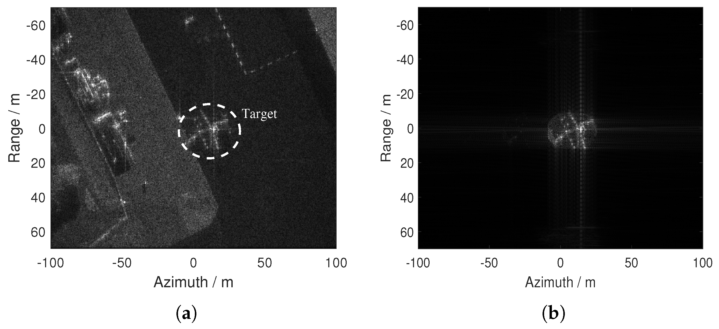
To further present the performance of our proposed Method 2, the measured mini SAR complex imagery provided by the Sandia National Laboratories is used [30]. Since the comparison between the two methods has been made in the previous section and the performance with the SAR data when applying Method 1 has been presented in [24], here only the peformance of the proposed Method 2 is presented in this section. Table 2 presents the main parameters of the SAR imaging scene.
Figure 7a presents the original SAR image by the Range Doppler Algorithm. A dotted circle is added to indicate the position of the plane target that needs to be cancelled. The raw signal of the target is inverted using the algorithm proposed in [31], then the target echo is simulated as shown in Figure 7b.
4.3.1. Cancellation Results
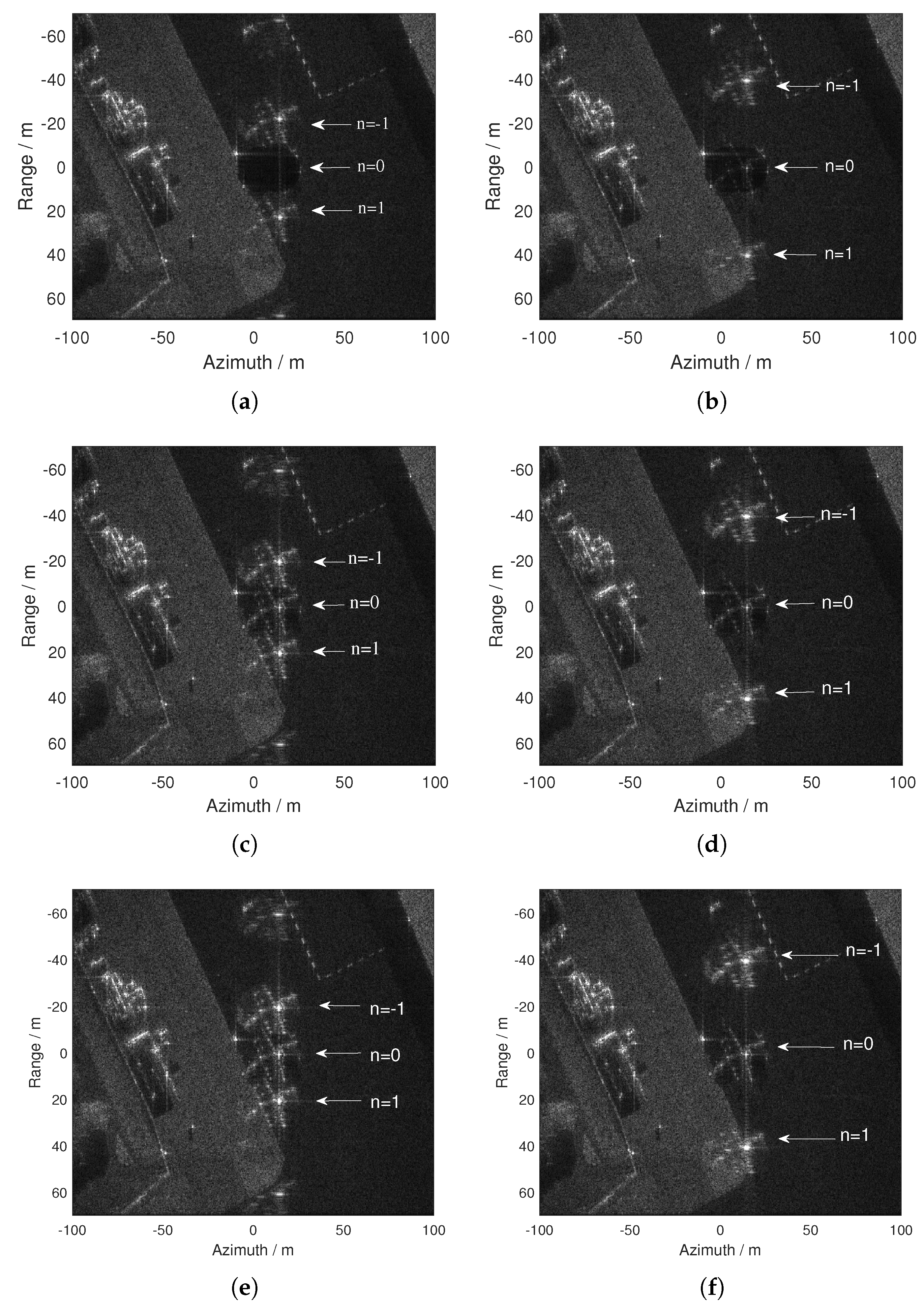
By calculation, the frequency shift = 12.2 MHz, the time-delay = 0.082 us. Firstly assume the jammer power is ideally set to guarantee the amplitude match at radar receiver. Figure 8a,b present the cancellation results with interrupted sampling frequencies set as = 20 MHz and = 40 MHz respectively, and the sampling duty ratio is 50%.
As shown in Figure 8a,b, the target echo is successfully cancelled by the proposed method. By calculation, the position of the order false targets should be ±20 m and ±40 m for = 20 MHz and = 40 MHz respectively, which is consistent with the results shown in Figure 8a,b. It indicates that the position of false targets is precisely adjusted by designs of the interrupted sampling frequency as expected.
Similarly, the cancellation results with amplitude mismatch are presented in Figure 8c–f, where the amplitude mismatch degree is set as = 50% and = 80% respectively. As revealed in Figure 8c–f, the target echo cannot be ideally cancelled with amplitude mismatch. The target becomes more and more obvious with the increase of the amplitude mismatch. However, the amplitude of target greatly reduces and the target is less visible in SAR image due to the cancellation compared with original image. Besides, the false targets can effectively shield the real target.
4.3.2. Evaluation of the Cancellation Performance
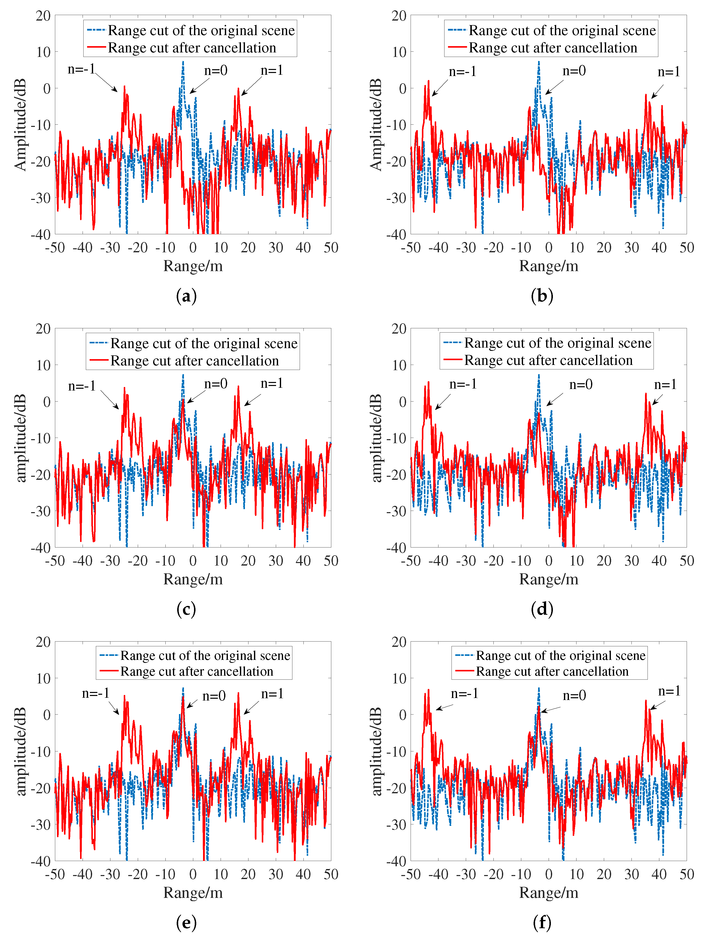
To access the performance of cancellation, Figure 9 presents the range cuts of Figure 8 in azimuth unit 20 m, where the dotted blue lines represent the range cuts of the original SAR image, and the red lines represent the range cuts after cancellation.
As revealed in Figure 9a,b, in terms of the absort amplitude of the imaging result, there is more than a 20 dB drop in the vicinity of target due to the presence of cancellation signal with ideal cancellation assumptions. After cancellation, the amplitude of the false target is much larger than that of the real target, which makes the radar difficult to distinguish the real target. As revealed in Figure 9c–f, the amplitude of the real target reduces by 10 dB and 5 dB approximately after cancellation in the presence of 50% and 80% amplitude mismatch, respectively. Thus the cancellation performance gets worse in the presence of amplitude mismatch compared with the ideal cancellation conditions. However, the amplitude of generated false target is about 5 dB larger ( = 50%) and 3 dB larger ( = 80%) than the amplitude of real target, thus the false targets can still effectively protect the real target by stronger amplitude response.
5. Conclusions
In this paper, an improved radar target echo cancellation method that uses frequency shifting modulation is proposed. The proposal uses the frequency shifting modulation to cancel the radar target echo using 0 order false targets produced by ISRJ. Compared with the existing method, the improved method utilizes the jammer power more efficiently, and more flexible jamming performance can be obtained. Besides, the real target can still be effectively protected by the preceded false target even with amplitude mismatch. Simulation results and measured SAR data experiments demonstrate its effectiveness. This work provides good information towards future jammer designs. In futhre work, further investigations on the influence of measuring accuracies of the radar signal parameters will be conducted. Besides, the hardware system designs of the canceller will be another important topic.
Author Contributions
Data curation, F.Z. and J.W.; Formal analysis, Q.W.; Funding acquisition, F.Z.; Investigation, X.L. and S.X.; Validation, Q.W., X.L. and S.X.; Writing—original draft, Q.W. and F.Z.; Writing—review & editing, Q.W. and F.Z.
Funding
This work was supported by the National Natural Science Foundation of China (Grant No. 61890542).
Conflicts of Interest
The authors declare no conflict of interest.
References
- Skolnik. Introduction to Radar Systems; McGraw-Hill: Boston, MA, USA, 2001. [Google Scholar]
- Liu, Y.; Wang, W.; Pan, X.; Dai, D.; Feng, D. A frequency-domain three-stage algorithm for active deception jamming against synthetic aperture radar. IET Radar Sonar Navigat. 2014, 8, 639–646. [Google Scholar] [CrossRef]
- Xu, L.; Feng, D.; Wang, X. Improved synthetic aperture radar micro-Doppler jamming method based on phase-switched screen. IET Radar Sonar Navigat. 2016, 10, 525–534. [Google Scholar] [CrossRef]
- Zhang, R.; Cao, S. 3D imaging millimeter wave circular synthetic aperture radar. Sensors 2017, 17, 1419. [Google Scholar] [CrossRef] [PubMed]
- Wang, X.; Liu, J.; Zhang, W.; Fu, Q.; Liu, Z.; Xie, X. Mathematic principles of interrupted-sampling repeater jamming (ISRJ). Sci. China-Inf. Sci. 2006, 50, 891–901. [Google Scholar] [CrossRef]
- Feng, D.; Tao, H.; Yang, Y.; Liu, Z. Jamming dechirping radar using interrupted-sampling repeater. Sci. China-Inf. Sci. 2011, 54, 2138–2146. [Google Scholar] [CrossRef]
- Almslmany, A.; Cao, Q.; Wang, C. A new airborne self-protection jammer for countering ground radars based on sub-Nyquist. IEICE Electron. Express 2015, 12, 2138–2149. [Google Scholar] [CrossRef]
- Feng, D.; Xu, L.; Pan, X.; Wang, X. Jamming wideband radar using interrupted-sampling repeater. IEEE Trans. Aerosp. Electron. Syst. 2017, 53, 1341–1354. [Google Scholar] [CrossRef]
- Tai, N.; Cui, K.; Wang, C.; Yuan, N. The design of a novel coherent noise jammer against LFM radar. IEICE Electron. Express 2016, 13, 2138–2149. [Google Scholar] [CrossRef]
- Wu, X.; Wang, X.; Lu, H. Study of intermittent-sampling repeater jamming to SAR. J. Astronaut. 2009, 30, 2043–2048. [Google Scholar]
- Wang, W.; Pan, X.; Liu, Y.; Feng, D.J.; Fu, Q.X. Sub-Nyquist sampling jamming against ISAR with compressed sensing. IEEE Sensors J. 2014, 14, 3131–3136. [Google Scholar] [CrossRef]
- Pan, X.; Wang, W.; Feng, D.; Liu, Y.; Fu, Q.; Wang, G. On deception jamming for countering ISAR based on sub-Nyquist sampling. IET Radar Sonar Navigat. 2014, 8, 173–179. [Google Scholar] [CrossRef]
- Gong, S.; Wei, X.; Li, X. ECCM scheme against interrupted sampling repeater jammer based on time-frequency analysis. J. Syst. Eng. Electron. 2014, 25, 996–1003. [Google Scholar] [CrossRef]
- Meller, M. Cheap Cancellation of Strong Echoes for Digital Passive and Noise Radars. IEEE Trans. Signal Process 2012, 60, 2654–2659. [Google Scholar] [CrossRef]
- Lu, Y.; Fowler, R.; Tian, W.; Thompson, L. Enhancing Echo Cancellation via Estimation of Delay. IEEE Trans. Signal Process 2005, 53, 4159–4168. [Google Scholar]
- Wang, Y.; Zhao, G.; Wang, H. Echo cancelling algorithm for the LFM radar. J. Xidian Univ. 2008, 6, 1031–1035. [Google Scholar]
- Ufimtsev, P.Y. Comment on Diffraction Principles and Limitations of RCS Reduction Techniques. Proc. IEEE 1996, 85, 1830–1851. [Google Scholar] [CrossRef]
- Xu, S.; Xu, Y. Simulation analysis of an active cancellation stealth system. Optik 2014, 125, 5273–5277. [Google Scholar]
- Yang, X.; Zhao, W.; Huang, L. Calculation of RCS of targets and statistical analysis of cancellation effect. Chin. J. Radio Sci. 2002, 17, 88–92. [Google Scholar]
- Xiang, Y.; Qu, C.; Su, F.; Yang, M. Active Cancellation Stealth Analysis of Warship for LFM Radar. Proc. ICSP 2010, 17, 2109–2112. [Google Scholar]
- Xiang, Y.; Qu, C.; Li, B.; Hou, H. Simulation Research on Cancellation Stealth of Warship Based on Its Radar Scattering Properties. J. Syst. Simul. 2013, 25, 104–110. [Google Scholar]
- Wei, Y.; Zhang, J.; Li, Z. A novel successive cancellation method to retrieve sea wave components form spatio-temporal remote sensing image sequences. Remote Sens. 2016, 8, 607. [Google Scholar] [CrossRef]
- Feng, D.; Xu, L.; Wang, W.; Yang, H. Radar target echo cancellation using interrupted-sampling repeater. IEICE Electron. Express 2014, 11, 1–6. [Google Scholar] [CrossRef]
- Xu, L.; Feng, D.; Dai, D.; Pan, X.; Wang, X. A Dual-Antenna Active-Echo-Cancellation Method for Synthetic Aperture Radar. In Proceedings of the 10th European Conference on Antennas and Propagation (EuCAP), Davos, Switzerland, 10–15 April 2016; pp. 1–5. [Google Scholar]
- Wu, Q.; Liu, J.; Wang, J.; Zhao, F.; Xiao, S. Improved Active Echo Cancellation Against Synthetic Aperture Radar Based on Non periodic Interrupted Sampling Modulation. IEEE Sens. J. 2018, 18, 4453–4461. [Google Scholar] [CrossRef]
- Hanbali, S.; Kastantin, R. Technique to counter active echo cancellation of self-protection ISRJ. IET Electron. Lett. 2017, 53, 680–681. [Google Scholar] [CrossRef]
- Xu, L.; Feng, D.; Liu, Y.; Pan, X.; Wang, X. A three-stage active cancellation method against synthetic aperture radar. IEEE Sensors J. 2015, 15, 6173–6178. [Google Scholar] [CrossRef]
- Hanbali, S.; Kastantin, R. Countering a self-protection frequency-shifting jamming against LFM pulse compression radars. INTL J. Electron. Telecommun. 2017, 63, 145–150. [Google Scholar] [CrossRef]
- Yang, Y.; Zhang, W.M.; Yang, J.H. Study on frequency-shifting jamming to linear frequency modulation pulse compression radars. In Proceedings of the 2009 International Conference on Wireless Communications & Signal Processing, Nanjing, China, 13–15 November 2009; pp. 1–5. [Google Scholar]
- The Sandia Complex Image. 2006. Available online: https://www.sandia.gov/radar/complex-data/ (accessed on 10 December 2018).
- Franceschetti, G.; Guida, R.; Iodice, A.; Riccio, D.; Ruello, G. Efficient simulation of hybrid stripmap/spotlight SAR raw signals from extended scenes. IEEE Trans. Geosci. Remote Sens. 2004, 42, 2385–2396. [Google Scholar] [CrossRef]
Figure 1.
Signal model of interrupted sampling. (a) The interrupted sampling function. (b) Interrupted sampling of linear frequency modulation (LFM) signal.
Figure 1.
Signal model of interrupted sampling. (a) The interrupted sampling function. (b) Interrupted sampling of linear frequency modulation (LFM) signal.

Figure 2.
Block diagram of the canceller.

Figure 3.
Required jammer power of two methods.

Figure 4.
Target echo cancellation result with amplitude match. (a) matched filtering (MF) output of the interrupted-sampling repeater jamming (ISRJ) signal and target echo of Method 1. (b) MF output of the ISRJ signal and target echo of Method 2. (c) MF output after echo cancellation of Method 1. (d) MF output after echo cancellation of Method 2.
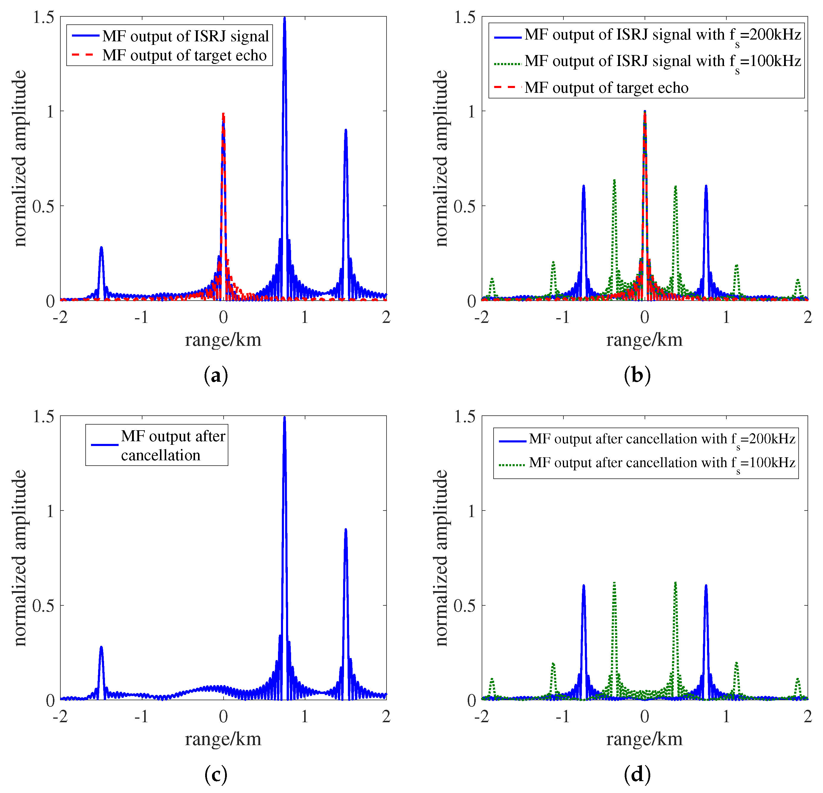
Figure 5.
Target echo cancellation result with amplitude mismatch ( = 200 kHz). (a) Method 1 ( = 50%). (b) Method 2 ( = 50%). (c) Method 1 ( = 80%). (d) Method 2 ( = 80%).
Figure 5.
Target echo cancellation result with amplitude mismatch ( = 200 kHz). (a) Method 1 ( = 50%). (b) Method 2 ( = 50%). (c) Method 1 ( = 80%). (d) Method 2 ( = 80%).
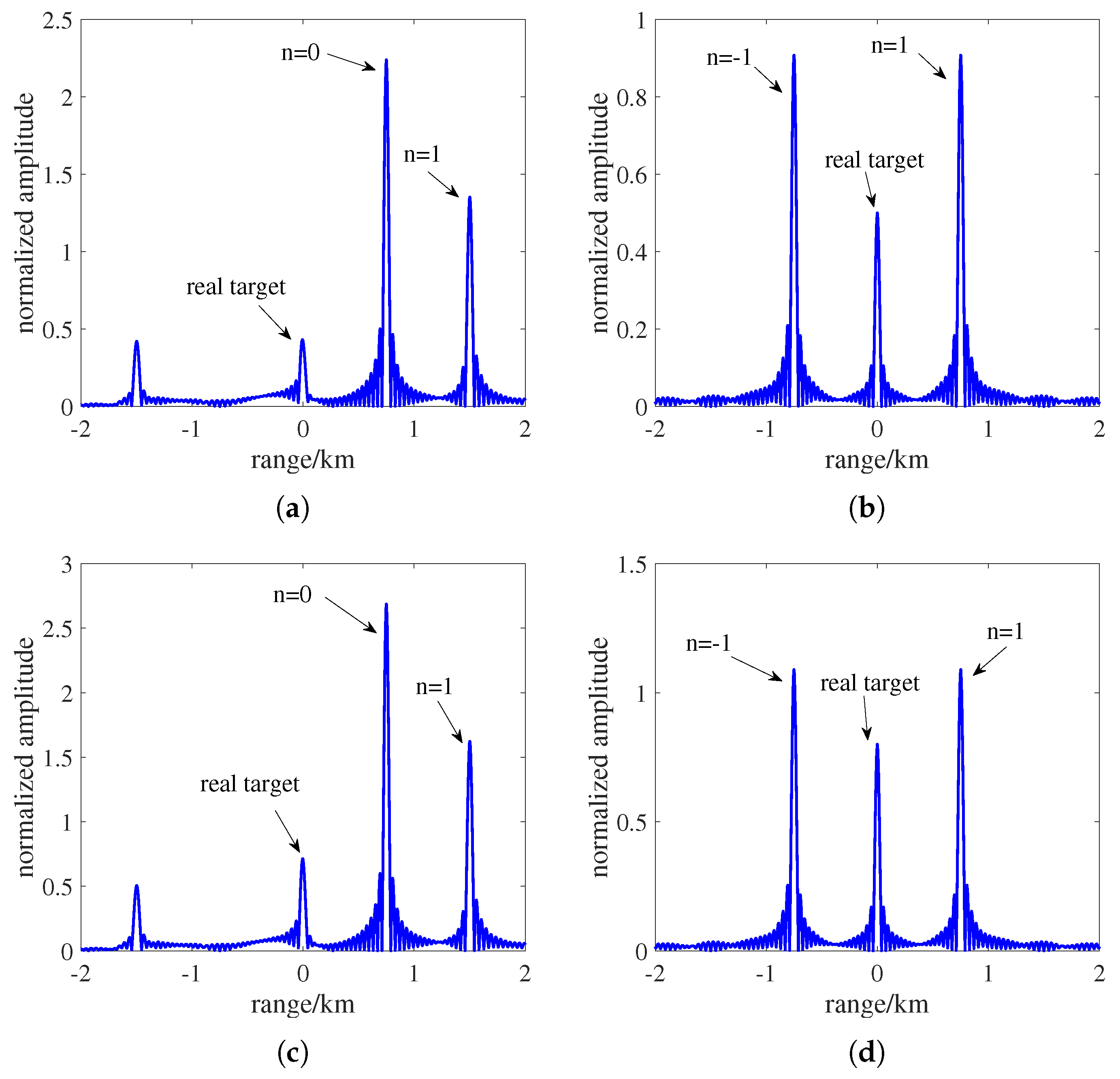
Figure 6.
Amplitude ratio of −1 order false target to real target after cancellation for Method 2.
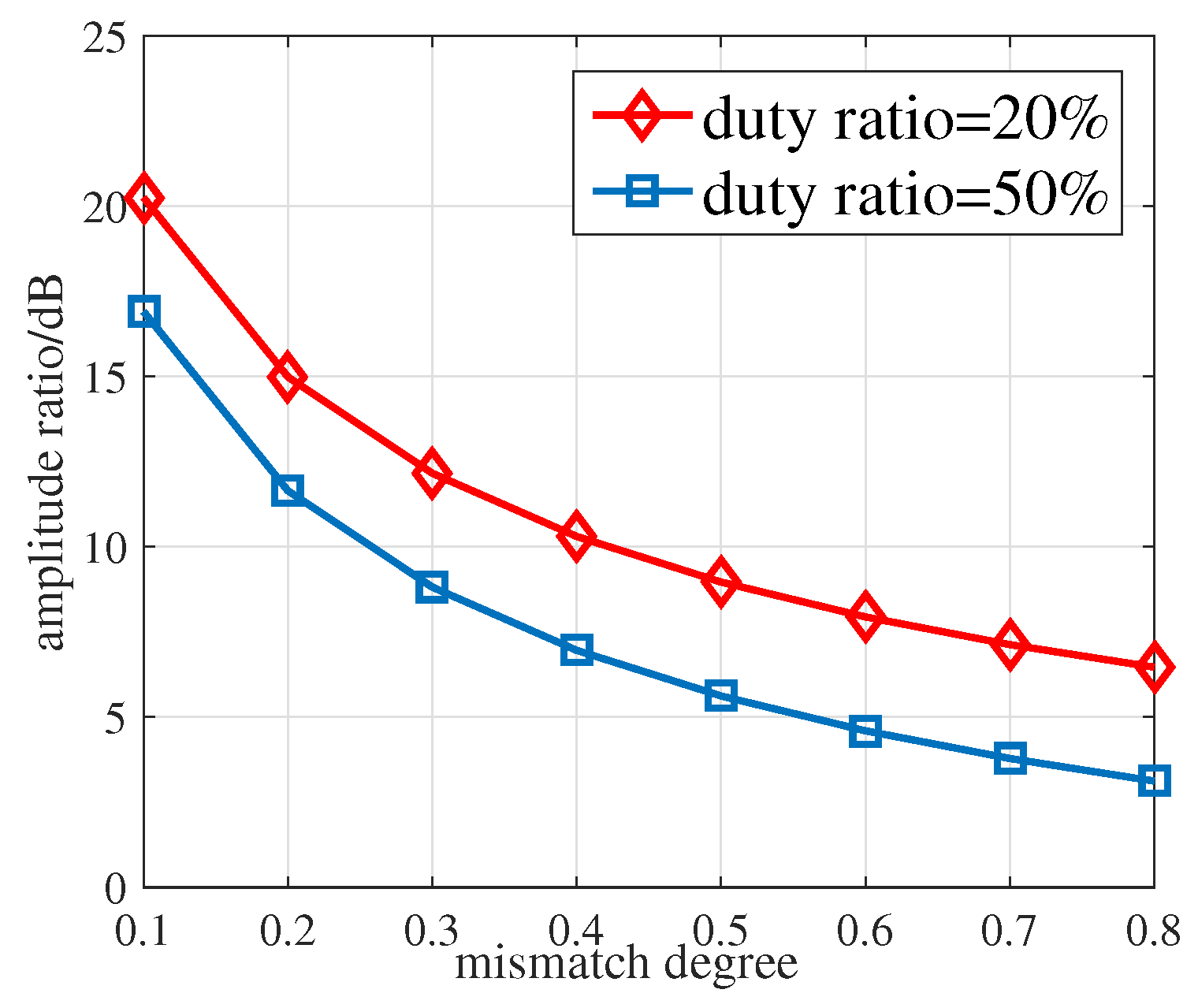
Figure 7.
Original synthetic aperture radar (SAR) scene. (a) The original image. (b) The target.

Figure 8.
Results of measured SAR data with the proposed method. (a) Ideal amplitude match ( = 20 MHz). (b) Ideal amplitude match ( = 40 MHz). (c) Amplitude mismatch ( = 50%, = 20 MHz). (d) Amplitude mismatch ( = 50%, = 40 MHz). (e) Amplitude mismatch ( = 80%, = 20 MHz). (f) Amplitude mismatch ( = 80%, = 40 MHz).

Figure 9.
Range cut at azimuth unit 20 m. (a) Ideal amplitude match ( = 20 MHz). (b) Ideal amplitude match ( = 40 MHz). (c) Amplitude mismatch ( = 50%, = 20 MHz). (d) Amplitude mismatch ( = 50%, = 40 MHz). (e) Amplitude mismatch ( = 80%, = 20 MHz). (f) Amplitude mismatch ( = 80%, = 40 MHz).
Figure 9.
Range cut at azimuth unit 20 m. (a) Ideal amplitude match ( = 20 MHz). (b) Ideal amplitude match ( = 40 MHz). (c) Amplitude mismatch ( = 50%, = 20 MHz). (d) Amplitude mismatch ( = 50%, = 40 MHz). (e) Amplitude mismatch ( = 80%, = 20 MHz). (f) Amplitude mismatch ( = 80%, = 40 MHz).


Table 1.
Main parameters of radar and target.
| Parameters | Value |
|---|---|
| radar antenna gain | 60 dB |
| peak power | 810 kW |
| pulse width | 100 us |
| chirp rate | Hz/s |
| target RCS | 0.1 m |
Table 2.
Main parameters of the synthetic aperture radar (SAR) imaging scene.
| Parameters | Value |
|---|---|
| Center frequency | 9 GHz |
| Resolution(range and azimuth) | 0.5 m×0.5 m |
| Platform velocity | 180 m/s |
| Odd number | 1001 |
| Chirp rate | 1.5 Hz/s |
© 2019 by the authors. Licensee MDPI, Basel, Switzerland. This article is an open access article distributed under the terms and conditions of the Creative Commons Attribution (CC BY) license (http://creativecommons.org/licenses/by/4.0/).
Share and Cite
MDPI and ACS Style
Wu, Q.; Zhao, F.; Wang, J.; Liu, X.; Xiao, S. Improved ISRJ-Based Radar Target Echo Cancellation Using Frequency Shifting Modulation. Electronics 2019, 8, 46. https://doi.org/10.3390/electronics8010046
AMA Style
Wu Q, Zhao F, Wang J, Liu X, Xiao S. Improved ISRJ-Based Radar Target Echo Cancellation Using Frequency Shifting Modulation. Electronics. 2019; 8(1):46. https://doi.org/10.3390/electronics8010046
Chicago/Turabian StyleWu, Qihua, Feng Zhao, Junjie Wang, Xiaobin Liu, and Shunping Xiao. 2019. "Improved ISRJ-Based Radar Target Echo Cancellation Using Frequency Shifting Modulation" Electronics 8, no. 1: 46. https://doi.org/10.3390/electronics8010046
Note that from the first issue of 2016, this journal uses article numbers instead of page numbers. See further details here.