Article

Quasi-Circulator Using an Asymmetric Coupler for Tx Leakage Cancellation

Department of Electronic Engineering, Yeungnam University, Gyeongbuk 38541, Korea
*
Author to whom correspondence should be addressed.
Electronics 2018, 7(9), 173; https://doi.org/10.3390/electronics7090173
Submission received: 20 July 2018 / Revised: 14 August 2018 / Accepted: 31 August 2018 / Published: 1 September 2018

Abstract

:
A quasi-circulator is proposed by using an asymmetric coupler with high isolation between the transmitting (Tx) and receiving (Rx) ports. The proposed quasi-circulator consists of quarter-wave transmission lines, which have unbalanced characteristic impedances and the terminated port, which is purposely unmatched with the reference impedance in the coupler. The port compensates for the asymmetric impedances of the coupler using the proposed design parameter. Because of its asymmetric structure and the usage of the unmatched port, the proposed circulator can be accurately designed to have high Tx–Rx isolation without increasing the signal losses in the Tx and Rx paths at the operating frequency. The proposed quasi-circulators show isolation improvements of 9.07 dB at 2.45 GHz and 7.95 dB at 24.125 GHz compared with conventional circulators using the symmetric couplers. The characteristic improvement of the proposed quasi-circulator was demonstrated by the increase of the detectable range of the 2.45 GHz Doppler radar sensor with the quasi-circulator.

1. Introduction

In electromagnetic-wave application systems such as radar sensors and wireless communication systems, the number and size of antennas should be considered in the implementation of the miniaturized module [1,2,3,4]. Since the antenna size depends on the operating frequency, it is more effective to reduce the number of antennas. The circulators can be used to reduce two antennas to one but it is not suitable for miniaturization because it is made of expensive directional materials or has disadvantages such as large size and heavyweight [5,6,7]. The planar quasi-circulator is a useful component in separating transmitting (Tx) and receiving (Rx) signals in miniaturized monostatic radar and communication systems that use a single antenna to transmit and receive wireless signals [4,8,9]. A branch-line coupler with a terminated port is conventionally used for a planar quasi-circulator because of its simple and low-cost design and its realization on a printed circuit board (PCB) [4,8,9,10,11]. However, the low isolation of the branch-line coupler between the Tx and Rx paths, which lowers the Rx sensitivity or saturates the receiver, causes a receiver malfunction and limits the maximum detectable range [4,8,9,10,11,12,13]. In previous studies, quasi-circulators using two branch-line couplers, a coupled-line directional coupler and a directional coupler with a flat coupling were developed as the planar quasi-circulator to improve the isolation [9,10,11,12]. The isolation between the Tx and Rx ports increased considerably in previous circulators; however, their size also increased because of the additional components. In addition, insertion losses at all ports increased when the Tx and Rx signals passed through those circulators. Previous studies to reduce the effect of the Tx leakage signals applied to a balanced topology for radar systems [4,14,15,16]. In this topology, it is necessary for Tx leakage cancellation to generate multiphase Tx signals. The topology also requires a symmetric structure consisting of several couplers and a power combiner, which may have a limit to reduce the size of the system.
While implementing the conventional quasi-circulator using the branch-line coupler, it is not easy to design the characteristics of the circulator accurately, especially the frequency at which the Tx leakage signal is minimized in the operating frequency band. In particular, since the line width of the transmission line cannot be neglected at the T-junction where the three transmission lines meet at one point, the conventional design parameters of the coupler should be modified. Because of the physical size of the T-junction, it is difficult to accurately design the length of the transmission line to the quarter-wavelength as in the electromagnetic-wave theory [17,18,19]. The T-junction creates a discontinuous section of the electromagnetic wave propagation in the branch-line coupler, so it can also lead to the performance degradation and frequency shift of the coupler implemented using the simple analytic design method. In addition, the design difficulty increases significantly with shorter wavelengths resulting in increased characteristic errors in the component design with higher operating frequencies. The symmetrical implementation is an important characteristic in the conventional quasi-circulator because the parasitic components and the process variation in the PCB fabrication degrade the operating characteristics at the desired frequency or change the operating frequency which is different from the design [20]. The uniformity of the signal pattern realized by the etching process can also be reduced in the fabrication process [21].
In this paper, a quasi-circulator using an asymmetric branch-line coupler is proposed to improve the isolation between the Tx and Rx ports at the operating frequency based on a novel design methodology. The characteristic impedances of the quarter-wave transmission lines are designed with an asymmetric structure and the impedance at the unused port of the coupler is designed differently from the reference impedance to compensate for the asymmetric characteristic impedances of the transmission lines. Compared with the asymmetric branch-line couplers presented in previous studies [22,23], the asymmetric coupler proposed for the circulator in this work has three input/output ports fixed at the reference impedance of 50 Ω so that the conventional circulator component can be replaced as it is. In contrast to the previous studies, the proposed quasi-circulator adjusts the line widths of the transmission lines asymmetrically and compensates for the asymmetric characteristics using resistor(s) connected to port 4 of the coupler. The asymmetric coupler can be easily implemented because the desired characteristic impedance of the transmission line can be obtained by designing the line width in the microstrip structure. The characteristics due to the asymmetric transmission lines of the coupler are compensated by adjusting the impedance of the single port, which is simply implemented by high-frequency resistors. The proposed quasi-circulator has high Tx–Rx isolation at the operating frequency, while the frequency with high Tx–Rx isolation in the conventional circulator was shifted from the designed frequency. The insertion and return losses of the proposed quasi-circulator are similar to those of the conventional quasi-circulator. The remainder of the paper is organized as follows. Section 2 describes the design methodology of the circulator using the asymmetric coupler. The implementation and design parameters of the circulators, operating at 2.45 GHz and 24.125 GHz, are detailed in Section 3. Section 4 provides the measured performances and comparison with conventional quasi-circulators using symmetric branch-line couplers. A conclusion is presented in Section 5.

2. Design of the Quasi-Circulator Using the Asymmetric Coupler

The asymmetric branch-line coupler for the proposed circulator consists of four unbalanced quarter-wave transmission lines that have different characteristic impedances. The characteristic impedances are obtained by regulating the line width, defined as Zi (i = 1–4), as shown in Figure 1. In the conventional branch-line coupler, the characteristic impedances between the opposing transmission lines are the same, that is, Z1 and Z2 are equal to Z3 and Z4, respectively. Three terminals from ports 1 to 3 are connected to a transmitter, antenna and receiver, respectively, using the transmission lines with a reference characteristic impedance Z50, which is 50 Ω. Port 4 is terminated using the certain impedance ZISO, which is purposely unmatched with the reference impedance. The unmatched ratio at port 4 of the proposed asymmetric coupler is defined as the parameter m, which is the ratio of the reflection coefficient between the unmatched and matched impedance conditions and is given as
m = S 44 S 44 | m a t c h e d ,
where S44|matched is the reflection coefficient at the matched condition and S44 is the reflection coefficient at port 4 of the proposed branch-line coupler. Because the reflection coefficient at the matched port, S44|matched, should ideally be 0, m can be defined in the range from 1 at the matched condition to infinite at the mismatched condition. When the three ports of the proposed circulator are perfectly matched to the reference impedance 50 Ω, the S-parameter matrix of the proposed asymmetric branch-line coupler can be expressed (2) by the reciprocal property [24] as follows:
[ S ] = [ 0 S 21 S 31 S 41 S 21 0 S 32 S 42 S 31 S 32 0 S 43 S 41 S 42 S 43 S 44 ] .
Assuming that each port in the coupler is mutually independent [24], the relationship between the transmitted signals to ports 3 and 4 can be obtained from (2) as follows:
S 31 S 32 + S 41 S 42 = 0 ,
S 31 S 41 + S 32 S 42 + S 43 S 44 = 0 ,
S 21 S 32 + S 41 S 43 = 0 ,
Using the complex conjugate of the S-parameters, (3) and (4) can be modified as
S 31 S 32 S 42 + S 41 | S 42 | 2 = 0 ,
| S 31 | 2 S 41 + S 31 S 32 S 42 + S 31 S 43 S 44 = 0 .
The first term of (6) and the second term of (7) are cancelled after subtracting (6) from (7) and (8) can be obtained as
S 41 ( | S 31 | 2 | S 42 | 2 ) + S 31 S 43 S 44 = 0 .
Assuming that the coupler is lossless, the second and the third rows of (2) can be expressed as
| S 31 | 2 + | S 32 | 2 + | S 43 | 2 = 1 ,
| S 21 | 2 + | S 32 | 2 + | S 42 | 2 = 1 ,
and (8) can be modified to (11) using the relationship between (9) and (10) as
S 41 ( | S 21 | 2 | S 43 | 2 ) + S 43 S 44 S 31 = 0 .
Substituting (5) into (11) for S31 after modifying (5) for S41*, the magnitude of the Tx leakage isolation |S31| can be expressed as
| S 31 | = | S 31 | = | 1 K 2 K 2 | | S 21 | | S 32 | | S 44 | .
where the parameter K is the transmission ratio between the paths from ports 1 to 2 and from ports 3 to 4, which represents the effect of the different characteristic impedances. Considering that the reflection signal at port 4 cannot be neglected, K can be expressed using the parameter k, which represents the effect on the different impedances of the matched ports and the parameter m as follows:
K = S 43 S 21 = k m ,
k = S 43 | m a t c h e d S 21 .
From (1) and (13), (12) can be expressed as
| S 31 | = | 1 k 2 m 2 k 2 m 3 | | S 21 | | S 32 | | S 44 | m a t c h e d | .
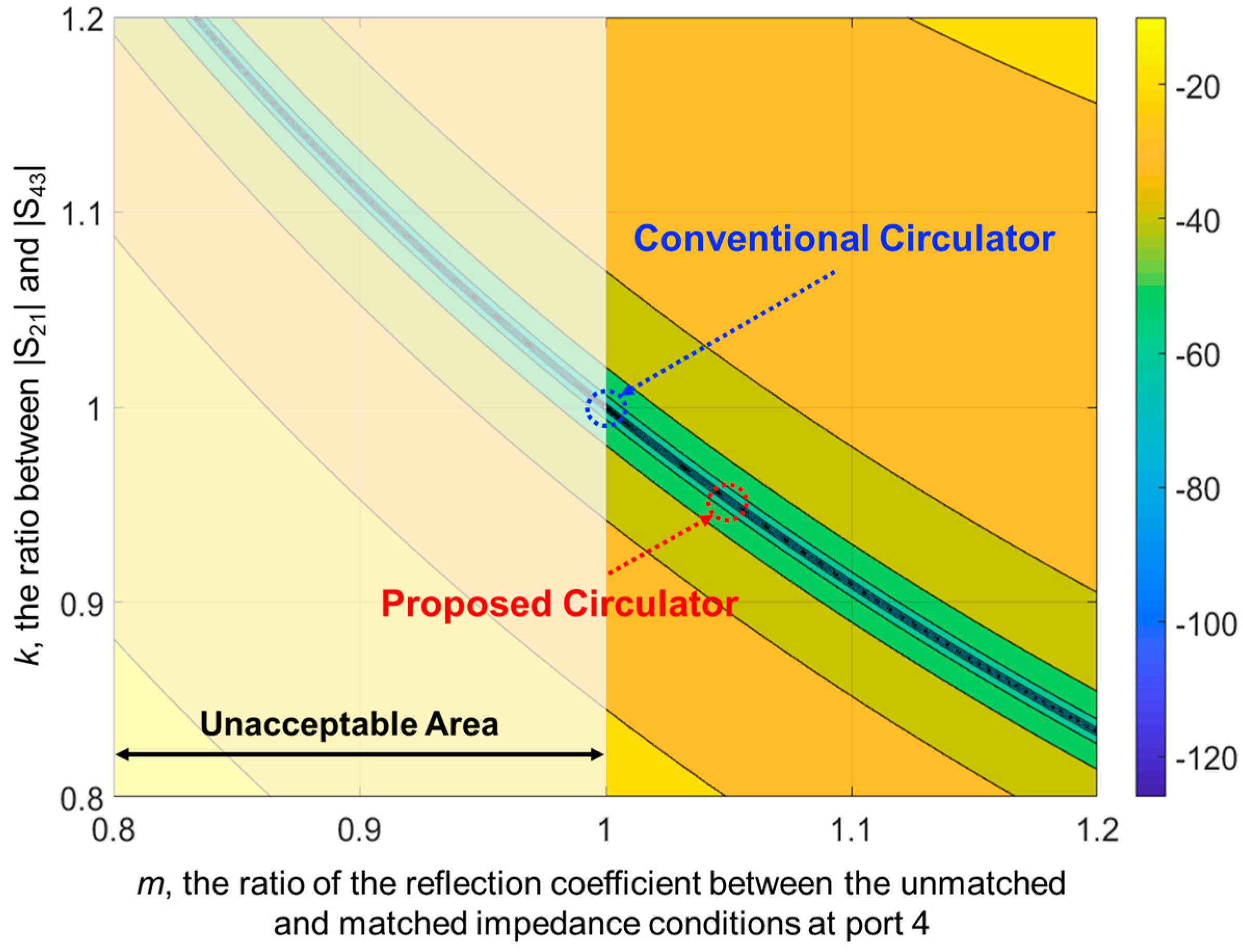
Figure 2 shows the variation in the magnitude of the Tx leakage signals in the branch-line coupler depending on k and m. The design equation D to minimize the Tx leakage signals is derived from (15) as follows:
D = | k m | = 1 .
High Tx–Rx isolation can be obtained from (14), which shows that k can be compensated by adjusting m to improve the isolation between the Tx and Rx ports.
In the conventional circulator using the symmetric coupler, the parameters k and m of (16) are each designed to be 1. Although the conventional circulator theoretically satisfies (16), the leakage signals that cannot be ignored in the monostatic radar and the wireless communication systems remain in the actual implemented circulator. The transmission lines in the coupler must be precisely implemented with a quarter-wave length to obtain k as 1. However, since the deviation of the line width of the transmission lines connected at one node cannot be neglected, realizing the quarter-wave transmission lines in the coupler implementation is difficult. Figure 3 shows the difference between the ideal and actual interconnections of the transmission lines in the conventional branch-line coupler. Theoretically, the lengths and widths of all the transmission lines in the branch-line coupler are designed to the quarter-wavelength L1 of the operating frequency and the widths W1 and W2 by the characteristic impedances of the lines. However, the lines cannot meet at the single point in the implementation of the coupler and the T-junction should be used to connect the lines as shown in Figure 3b. The line length of the coupler cannot be the same as the theoretical quarter-wavelength L1 because of the physical size of the T-junction. The design inaccuracy increases in the implementation of the coupler since the design that approximates the length to L1′ or L1″ in Figure 3b considering the dimension of the junction cannot be regarded as the accurate design methodology. The size of the junction is almost frequency-independent since it is mainly designed by the widths W1 and W2 depending on the characteristics of the substrate. The design error by the junction increases in the implementation as the operating frequency increases because the quarter-wavelength decreases but the size of the junction is almost constant depending on the increase in frequency. This produces the non-ideal characteristics in the symmetric branch-line coupler and the value of k in the implemented coupler becomes a different parameter with the design value of 1. The multiple reflections and transmissions, the substrate and propagation losses and other parasitic effects should be considered to accurately design the value of k when implementing the branch-line coupler. However, the complexity of the design can increase. The characteristics of the coupler are especially sensitive to the change in the physical size of the T-junction due to fabrication error. This is the main reason why it is difficult to accurately design the branch-line coupler on the PCB in the millimeter-wave frequency bands. The characteristic changes caused by the T-junction can be modified by optimizing the theoretical design parameters using the electromagnetic wave simulation but there is a problem that the optimization process is required for each design every time. For improving the isolation by reducing the effect of the T-junction, the proposed quasi-circulator using the asymmetric branch-line coupler increases the degree of design freedom by using the specific k parameter and the m parameter to compensate for the k parameter. When the k parameter is set to a value that is excessively smaller than 1, the width of the transmission line becomes thinner in the realization on the PCB because of the increase in the characteristic impedance of the line. The excessively thin width of the line can cause performance degradation because of the process tolerance for the fabrication of the PCB. In the proposed quasi-circulator, the parameters k and m of (16) are 0.947 and 1.053, respectively.

3. Implementation of the Proposed and Conventional Quasi-Circulators

The conventional quasi-circulator using the branch-line coupler consists of four quarter-wave transmission lines with characteristic impedances Z1 and Z3 of 35.4 Ω and Z2 and Z4 of 50 Ω, as shown in Figure 1, respectively [24]. Port 4 of the conventional circulator is terminated with the reference impedance Z50. Based on the design parameters k and m in Section 2, the characteristic impedances Z1, Z2, Z3 and Z4 of the transmission line and the termination impedance ZISO are obtained in the proposed circulator using the asymmetric coupler. To reduce the size of the T-junction, the characteristic impedances Z1 and Z4 in the proposed circulator are designed to 40 Ω and 60 Ω, respectively. The value of k in the circulator is obtained by using Z2 of 45 Ω and Z3 of 35 Ω. Unbalanced impedances of the transmission lines are compensated by using ZISO of 45 Ω to achieve the desired value of m at port 4. All circulators were simulated using a Keysight Advanced Design Systems Momentum electromagnetic-wave (EM) simulator considering the dielectric constants, loss tangents and thicknesses of PCBs.

3.1. Quasi-Circulators for 2.45 GHz

The asymmetric and symmetric couplers, operating at a 2.45 GHz frequency band, were fabricated on an FR4 PCB with a dielectric constant of 4.3 of 39 mm × 30 mm and 35 mm × 30 mm and a thickness of 1 mm, as shown in Figure 4. In the conventional circulator using the symmetric coupler, the widths W1 and W2 of the transmission lines with the characteristic impedances 35.4 Ω and 50 Ω were designed to be 3.3 mm and 1.9 mm, respectively. Although the quarter-wavelength at 2.45 GHz is 14.8 mm on the FR4 PCB, the lengths of the transmission lines in Figure 4a were designed by including the size of the junction as 16 mm, 17.9 mm, 16 mm and 17.3 mm, respectively. Using the designed characteristic impedances Z1, Z2, Z3 and Z4, the widths of the transmission lines in the proposed circulator were designed to be 2.6 mm, 2.2 mm, 3.3 mm and 1.3 mm, respectively. Because the size of the T-junction was changed by the designed impedances, the lengths of the transmission lines in Figure 4b were modified to be 16 mm, 17.8 mm, 16 mm and 16.9 mm, respectively. The design accuracy can be increased in the proposed circulator because the lengths of the proposed circulator were reduced as compared with the lengths of the conventional circulator. The termination resistance at port 4 was realized using a single 45 Ω resistor with the size of 10 mm × 5 mm made by Murata Manufacturing Co., Ltd. (Nagaokakyo, Kyoto, Japan).
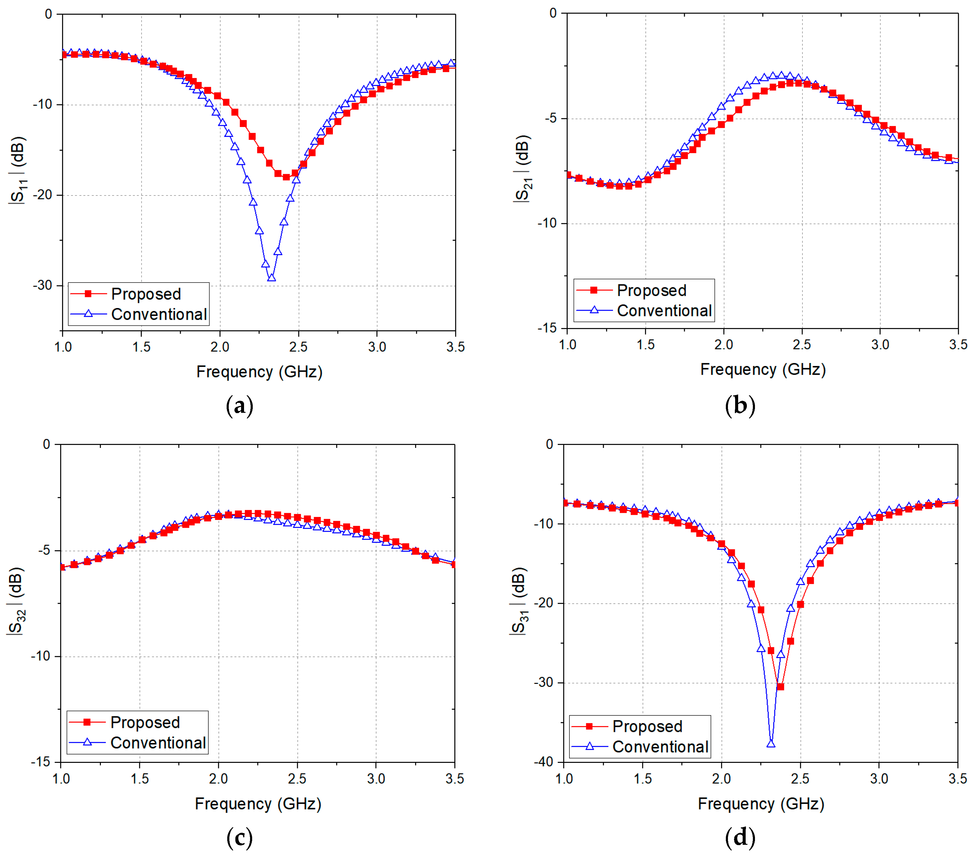
Figure 5 shows the simulation results for the quasi-circulators. The operating frequency of the conventional circulator is lower than the design frequency of 2.45 GHz but the frequency of the proposed circulator is almost the same as the design frequency. In addition, the proposed circulator shows |S21| of −3.31 dB and |S32| of −3.39 dB at 2.45 GHz, which are similar to each other, whereas the conventional circulator obtains |S21| of −3.05 dB and |S32| of −3.74 dB at this frequency.

3.2. Quasi-Circulators for 24.125 GHz

As shown in Figure 6, the directional couplers operating at the 24.125 GHz frequency band were realized on an RO3003 PCB with a dielectric constant of 3.0 of 17 mm × 13 mm and a thickness of 10 mil. The losses caused by the length of the transmission line equally occurred in both of two couplers because the total size of the two PCBs is the same as each other. The widths of the conventional quasi-circulator were designed to be 1.0 mm and 0.6 mm for the transmission lines with the characteristic impedance of 35 Ω and 50 Ω, respectively. The quarter-wavelength at 24.125 GHz is 1.8 mm on the RO3003 PCB but the lengths of the transmission lines in the conventional circulator were implemented as 1.4 mm, 2.0 mm, 1.9 mm and 2.4 mm, respectively. The widths of the lines designed in the 24.125 GHz proposed quasi-circulator are 0.8 mm, 0.7 mm, 1.0 mm and 0.5 mm, respectively. The line lengths of the proposed circulator were individually designed to be 1.4 mm, 2.0 mm, 1.9 mm and 2.2 mm, respectively. As in the design of the 2.45 GHz circulators, the length on the left side was also reduced by 0.2 mm compared to the length of the conventional one. The resistance of 45 Ω at port 4 was implemented using high-frequency resistors of 50 Ω and 500 Ω in parallel, which were made by Vishay Intertechnology, Inc. (Malvern, PA, USA).
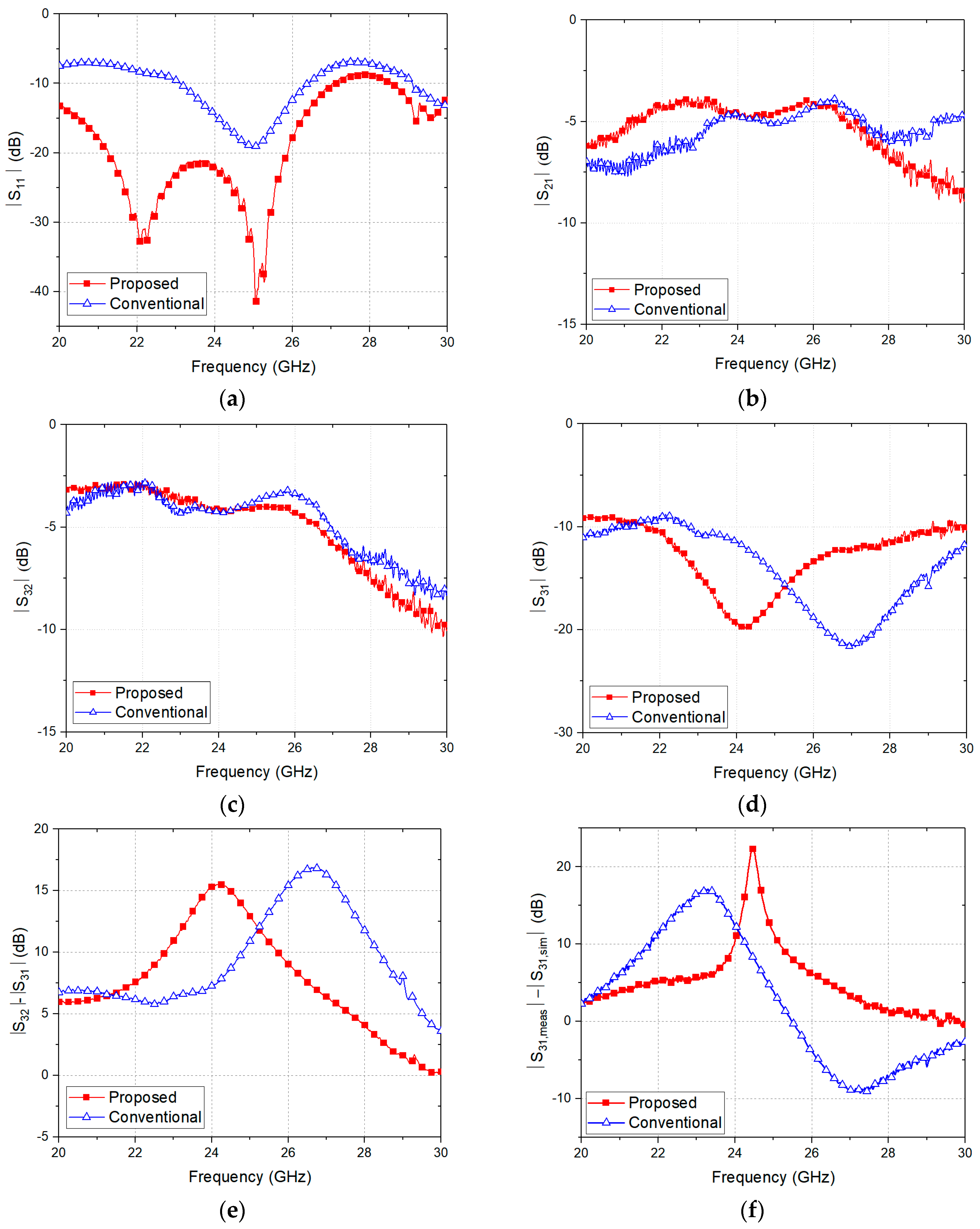
The simulation results in Figure 7 show that the proposed quasi-circulator designed at 24.125 GHz but the conventional quasi-circulator designed at a frequency lower than the desired frequency. These are similar characteristics to the simulation results of the 2.45 GHz quasi-circulators. The insertion losses in the Tx and Rx paths are well balanced in the simulation results of the proposed circulator. Note that a conventional circulator could be well optimized to have accurate characteristics at the operating frequency but it takes a long time to design because the physical lengths and line widths of the transmission lines must be determined by parametric optimization. The simulation results considering the physical size of the T-junction show that the proposed circulator can be exactly designed at the desired operating frequency without the complicated optimization process.

4. Measurement Results of the Proposed Quasi-Circulators.

4.1. Quasi-Circulators for 2.45 GHz

Figure 8 shows the measured S-parameters of the proposed and conventional quasi-circulators at the frequency band. The isolation between the Tx and Rx ports increased by 9.07 dB at 2.45 GHz and the frequency bandwidth in which the isolation is less than −20 dB extended from 140 MHz to 250 MHz. The frequency with the high Tx–Rx isolation of the proposed circulator is set to be 2.45 GHz, which is the same as the designed operating frequency. On the other hand, the frequency of the conventional circulator shifted from 2.45 GHz to 2.34 GHz despite its precise design. The magnitude of S21 and S32 of the proposed circulator are measured as −3.64 and −3.52 dB, respectively, which are well-balanced compared to those of the conventional circulator. The losses in the Tx and Rx paths of the proposed circulator are similar to those of the conventional circulator. The detailed measurement results of the proposed circulator, compared with the conventional circulator, show an increase of 0.45 dB in the Tx-path loss and a decrease of 0.32 dB in the Rx path loss. As the insertion loss represents the signal attenuation from the Tx and the antenna ports, the Tx path loss can show the efficiency of the circulator for the transmitted signals. Measurement results indicate that the efficiency of the proposed circulator at 2.45 GHz can be less in the transmitted signals than in the conventional circulator, based on the additional Tx path loss of 0.45 dB. On the other hands, the efficiency of the circulator in the received signals at 2.45 GHz can be higher than the conventional circulator because of the difference of 9.39 dB between the Rx path loss and the Tx leakage isolation, which is shown in Figure 8e, has a positive effect on the Rx sensitivity. Figure 8f shows the difference between the simulation and measurement results of the Tx leakage isolation of the 2.45 GHz quasi-circulators. The difference shows that the design accuracy of the proposed quasi-circulator is higher in the measured frequency band than that of the conventional one. The peak in Figure 8f is based on the narrow band characteristics from the simulation result and it can be neglected from determining the accuracy from the comparison between the simulation and measurement because the isolation of less than −30 dB is difficult to realize in the implementation due to the leakage through the PCB substrate itself.

4.2. Quasi-Circulators for 24.125 GHz

The measured S-parameters of the proposed and conventional circulators are shown in Figure 9. The Tx leakage isolation of the proposed circulator at 24.125 GHz is better than the conventional circulator by 7.95 dB. Similar to the 2.45 GHz circulators, the magnitudes of S21 and S32 of the proposed circulator at 24.125 GHz are also almost the same and well-balanced. The minimum isolation in the proposed and conventional circulators are measured as −19.85 dB at 24.225 GHz and −21.67 dB at 27.115 GHz, respectively. The frequency with high isolation in the proposed circulator is shown in the operating frequency band, while the frequency of the conventional circulator is shown out of the frequency band. Figure 9d shows that the design error of the conventional circulator in the 24 GHz frequency band using the symmetric coupler is critically increased compared with the error in the circulator operating at 2.45 GHz in Figure 8d. It can be understood that the physical size of the T-junction has a greater effect on the circulator characteristics in the 24 GHz frequency band because the quarter-wavelength of the transmission lines is reduced to be comparable to the width of the lines. Since the effects on the parasitic components and the process errors increase more at the high frequency of 24.125 GHz than 2.45 GHz, the measurement results of the conventional quasi-circulator changed more in the simulation results. Although the parasitic components and the process errors were simultaneously generated between the two circulators in the same fabrication, the characteristics change of the proposed circulator were not shown in the results. The symmetrical coupler used in the conventional quasi-circulator may degrade greatly if the symmetricity of the coupler is broken but the asymmetrical coupler used in the proposed quasi-circulator does not show the degradation in the measurement. Therefore, it can be considered that the performance change in the proposed quasi-circulator is small due to the asymmetric coupler. The efficiency of the circulators in the transmitted signals can be almost the same because of the similar Tx path losses in the circulators but the efficiency of the proposed circulator for the received signals at 24.125 GHz can be higher than the conventional circulator owing to the difference of 8.04 dB shown in Figure 9e. The efficiency degradation in the Rx path is caused by the shift of the operating frequency in the conventional circulator. Figure 9f shows that the proposed quasi-circulator also has higher design accuracy than a conventional quasi-circulator because the isolation characteristics of less than −30 dB in the simulation results can be neglected. The results of the proposed quasi-circulators, as shown in Table 1, reveal the improved Tx leakage isolation and similar insertion losses at the designed operating frequency as compared with those of the conventional circulators.

4.3. Performance Improvement by the Proposed Quasi-Circulator at the 2.45 GHz Radar Sensor

The monostatic Doppler radar sensor shown in Figure 10 was demonstrated at 2.45 GHz to verify the performance improvement by reducing the Tx leakage isolation of the proposed circulator. The 2.45 GHz signal with the output power of −10 dBm is generated at the Keysight N5183B analog signal generator and the signal is divided into the Tx and Rx paths by the power splitter, which is manufactured by Mini-Circuits. A Tx signal is transmitted to the antenna through the quasi-circulator. The 2.45 GHz signal radiated from the patch antenna with the gain of 0 dBi is reflected by the metronome with 1 Hz vibration and transmitted to the Rx port of the quasi-circulator through the same antenna and the quasi-circulator. The received and the Tx leakage signals by the quasi-circulator are simultaneously transmitted to the Rx port and amplified with the voltage gain of 14 dB in the low noise amplifier. The received signal is mixed with the 2.45 GHz reference signal in the frequency mixer to produce a 1 Hz signal of the metronome motion in the baseband. The Tx leakage signal is shown near DC level after passing through the frequency mixer because of the fixed leakage path and is generally larger magnitude than the received signal. If the sensitivity is degraded by the increase of the Tx leakage signal, the amplitude of the 1 Hz signal of the metronome motion gradually decreases because the received signal is masked by the leakage signal. If the received signal is smaller than the level determined by the minimum sensitivity of the system, the 1 Hz signal cannot be detected in the baseband. Therefore, the improvement of the Tx leakage isolation by the proposed quasi-circulator can be verified by the increase of the received amplitude of the 1 Hz signal and the maximum detectable range from the radar sensor to the metronome.
The results shown in Figure 11 are the received signals of the radar sensors in the baseband for the metronome with 1 Hz motion measured at the distance from 0.5 m to 1 m. Figure 11a,b show that the radar sensor using the proposed quasi-circulator generates a smaller signal around the DC level due to the improvement of the Tx leakage isolation than the sensor using the conventional quasi-circulator. The metronome motion of the around 1 Hz signal was detected at 0.5 m by both sensors using the two quasi-circulators as shown in Figure 11c but the motion was only detected at 0.9 m by the radar sensor using the proposed quasi-circulator as shown in Figure 11d. The sensor using the conventional quasi-circulator detected the motion signal at 0.8 m but it did not show the signal at a longer distance than 0.8 m. The magnitude of the motion signal measured at 0.5 m distance was larger in the radar sensor using the proposed quasi-circulator than the sensor using the conventional quasi-circulator. The measurement results of the 2.45 GHz radar sensor show that the improvement of the Tx leakage isolation by the proposed quasi-circulator can improve the system performances of the radar sensor, especially the maximum detectable range.

5. Conclusions

A quasi-circulator that uses an asymmetric branch-line coupler is proposed for obtaining the optimal design characteristics at the operating frequency, including high Tx–Rx isolation. The asymmetric coupler for a highly isolated circulator is designed using the proposed design equation in (16), wherein the product of the asymmetric ratio of the characteristic impedances of the transmission lines and the unmatched ratio in the unused port of the coupler should be 1. The isolation improvements (compared with the conventional circulators) of 9.07 dB at 2.45 GHz and 7.95 dB at 24.125 GHz are achieved through the implementation of the proposed planar quasi-circulators. The frequencies with high Tx–Rx isolation in the conventional quasi-circulators are shifted but those of the proposed quasi-circulators are realized in the operating frequency bands. The insertion losses of the proposed quasi-circulators are balanced between the Tx and Rx paths and are similar to those of the conventional quasi-circulators. The maximum detectable range of the 2.45 GHz Doppler radar sensor was increased when the proposed quasi-circulator was used in the monostatic radar sensor.

Author Contributions

J.-R.Y. identified the framework of this study and defined the research theme. B.-Y.Y. and J.-R.Y. designed the circulators. B.-Y.Y. and J.-H.P. performed the measurements. All authors analyzed the data, wrote the paper and edited the manuscript.

Funding

This research was funded by the 2017 Yeungnam University Research Grant No. 217A580039. And this work was also supported by the Basic Science Research Program through the National Research Foundation of Korea (NRF) funded by the Ministry of Science, ICT and Future Planning (grant number 2017R1C1B2002285).

Conflicts of Interest

The authors declare no conflict of interest.

References

  1. Wang, X.; Che, W.; Yang, W.; Feng, W.; Gu, L. Self-interference cancellation antenna using auxiliary port reflection for full-duplex application, Self-interference cancellation antenna using auxiliary port reflection for full-duplex application. IEEE Antennas Wirel. Propag. Lett. 2017, 16, 2873–2876. [Google Scholar] [CrossRef]
  2. Meerasri, P.; Uthansakul, P.; Uthansakul, M. Self-interference cancellation-based mutual-coupling model for full-duplex single-channel mimo systems. Int. J. Antennas Propag. 2014, 2014, 1–10. [Google Scholar] [CrossRef]
  3. Mosallaei, H.; Sarabandi, K. Antenna miniaturization and bandwidth enhancement using a reactive impedance substrate. IEEE Trans. Antennas Propag. 2004, 52, 2403–2414. [Google Scholar] [CrossRef]
  4. Lee, H.L.; Lim, W.-G.; Oh, K.-S.; Yu, J.-W. 24 GHz balanced Doppler radar front-end with Tx leakage canceller for antenna impedance variation and mutual coupling. IEEE Trans. Antennas Propag. 2011, 59, 4497–4504. [Google Scholar] [CrossRef]
  5. Wada, T.; Nakajima, R.; Obiya, H.; Ogami, T.; Koshino, M.; Kawashima, M.; Nakajima, N. A miniaturized broadband lumped element circulator for reconfigurable front-end system. In Proceedings of the 2014 IEEE MTT-S International Microwave Symposium (IMS2014), Tampa, FL, USA, 1–6 June 2014. [Google Scholar]
  6. Saib, A.; Darques, M.; Piraux, L.; Vanhoenacker-Janvier, D.; Huynen, I. An unbiased integrated microstrip circulator based on magnetic nanowired substrate. IEEE Trans. Microw. Theory Tech. 2005, 53, 2043–2049. [Google Scholar] [CrossRef]
  7. Lee, J.; Hong, Y.-K.; Yun, C.; Lee, W.; Park, J.; Choi, B.-C. Magnetic parameters for ultra-high frequency (uhf) ferrite circulator design. J. Magn. 2014, 19, 399–403. [Google Scholar] [CrossRef]
  8. Sanna, G.; Montisci, G.; Jin, Z.; Fanti, A.; Casula, G.A. Design of a Low-Cost Microstrip Directional Coupler with High Coupling for a Motion Detection Sensor. Electronics 2018, 7, 25. [Google Scholar] [CrossRef]
  9. Kim, W.-K.; Na, W.; Yu, J.-W.; Lee, M.-Q. A high isolated coupled-line passive circulator for uhf rfid reader. Microw. Opt. Technol. Lett. 2008, 50, 2597–2600. [Google Scholar] [CrossRef]
  10. Adams, R.S.; O’Neil, B.; Young, J.L. The circulator and antenna as a single integrated system. IEEE Antennas Wirel. Propag. Lett. 2008, 8, 165–168. [Google Scholar] [CrossRef]
  11. Yang, J.-R.; Kim, D.-W.; Hong, S. Quasi-circulator for effective cancellation of transmitter leakage signals in monostatic six-port radar. Electron. Lett. 2009, 45, 1093–1095. [Google Scholar] [CrossRef]
  12. Lee, H.L.; Park, D.-H.; Yu, J.-W.; Lee, M.-Q. Compact antenna module with optimized Tx-to-Rx isolation for monostatic RFID. IEEE Microw. Wirel. Compon. Lett. 2017, 27, 1161–1163. [Google Scholar] [CrossRef]
  13. Chen, P.-W.; Lai, M.-T.; Tsao, H.-W.; Wu, J.-S. A high isolation quasi-circulator with self-adjusting technique. In Proceedings of the Asia-Pacific Microwave Conference, Sendai, Japan, 4–7 November 2014. [Google Scholar]
  14. Kim, C.-Y.; Kim, J.-G.; Hong, S. A quadrature radar topology with Tx leakage canceller for 24-ghz radar applications. IEEE Trans. Microw. Theory Tech. 2007, 55, 1438–1444. [Google Scholar] [CrossRef]
  15. Kim, J.-G.; Ko, S.; Jeon, S.; Park, J.-W.; Hong, S. Balanced topology to cancel Tx leakage in CW radar. IEEE Microw. Wirel. Compon. Lett. 2004, 14, 443–445. [Google Scholar] [Green Version]
  16. Mercuri, M.; Barmuta, P.; Soh, P.J.; Leroux, P.; Schreurs, D. Monostatic continuous-wave radar integrating a tunable wideband leakage canceler for indoor tagless localization. Int. J. Microw. Wirel. Technol. 2017, 9, 1583–1590. [Google Scholar] [CrossRef]
  17. Piazzon, L.; Saad, P.; Colantonio, P.; Giannini, F.; Andersson, K.; Fager, C. Branch-line coupler design operating in four arbitrary frequencies. IEEE Microw. Wirel. Compon. Lett. 2012, 22, 67–69. [Google Scholar] [CrossRef]
  18. Chang, W.-L.; Huang, T.-Y.; Shen, T.-M.; Chen, B.-C.; Wu, R.-B. Design of compact branch-line coupler with coupled resonators. In Proceedings of the 2007 Asia-Pacific Microwave Conference, Bangkok, Thailand, 11–14 December 2007. [Google Scholar]
  19. Wong, F.-L.; Cheng, K.-K.M. A novel planar branch-line coupler design for dual-band applications. In Proceedings of the 2004 IEEE MTT-S International Microwave Symposium Digest (IEEE Cat. No. 04CH37535), Fort Worth, TX, USA, 6–11 June 2004. [Google Scholar]
  20. Renbi, A.; Carlson, J.; Delsing, J. Impact of PCB manufacturing process variations on trace impedance. Internatial Symp. Microelectrics 2011, 2011, 891–895. [Google Scholar] [CrossRef]
  21. Ji, L.; Wang, C.; Wang, S.; Zhu, K.; He, W.; Xiao, D. Multi-physics coupling aid uniformity improvement in pattern plating. Circ. World 2016, 42, 69–76. [Google Scholar] [CrossRef]
  22. Ahn, H.-R.; Wolff, I. Asymmetric four-port and branch-line hybrids. IEEE Trans. Microw. Theory Tech. 2000, 48, 1585–1588. [Google Scholar]
  23. Ahn, H.-R. Asymmetric Passive Components in Microwave Integrated Circuits; Wiley: Weinheim, Germany, 2006; ISBN 978-0-471-73748-3. [Google Scholar]
  24. Pozar, D.M. Microwave Engineering, 4th ed.; Wiley: Weinheim, Germany, 2011; ISBN 978-0-470-63155-3. [Google Scholar]
Figure 1. Block diagram of the proposed quasi-circulator using an asymmetric branch-line coupler.
Electronics 07 00173 g001
Figure 2. Calculated Tx leakage levels depending on design parameters k and m.
Electronics 07 00173 g002
Figure 3. T-junction interconnection of the transmission lines in the conventional branch-line coupler: (a) theoretical description using a single point junction; (b) physical dimension in layout design for realization on a printed circuit board (PCB).
Electronics 07 00173 g003
Figure 4. 2.45 GHz quasi-circulators fabricated on an FR4 PCB: (a) the conventional circulator using a symmetrical branch-line coupler; (b) the proposed circulator using an asymmetrical branch-line coupler.
Electronics 07 00173 g004
Figure 5. Simulated S-parameters of the proposed and conventional quasi-circulators using 2.45 GHz asymmetric and symmetric branch-line couplers, respectively: (a) |S11| denotes the return loss at the Tx port; (b) |S21| denotes propagation gains in the Tx path; (c) |S32| denotes propagation gains in the Rx path; (d) |S31| denotes the Tx leakage isolation between the Tx and Rx ports.
Electronics 07 00173 g005
Figure 6. 24.125-GHz quasi-circulators fabricated on an RO3003 PCB: (a) conventional circulator; (b) proposed circulator.
Electronics 07 00173 g006
Figure 7. Simulated S-parameters of the proposed and conventional quasi-circulators at 24.125 GHz: (a) |S11|; (b) |S21|; (c) |S32|; (d) |S31|.
Electronics 07 00173 g007
Figure 8. Measured S-parameters of the proposed and conventional quasi-circulators at 2.45 GHz: (a) |S11|; (b) |S21|; (c) |S32|; (d) |S31|; (e) |S32|−|S31|; (f) the difference of |S31| between the simulation and the measurement.
Electronics 07 00173 g008aElectronics 07 00173 g008b
Figure 9. Measured S-parameters of the proposed and conventional quasi-circulators at 24.125 GHz: (a) |S11|; (b) |S21|; (c) |S32|; (d) |S31|; (e) |S32|−|S31|; (f) the difference of |S31| between the simulation and the measurement.
Electronics 07 00173 g009
Figure 10. Measurement setup for 2.45 GHz monostatic Doppler radar sensor using the quasi-circulator.
Electronics 07 00173 g010
Figure 11. Received signal amplitude in the 2.45 GHz monostatic Doppler radar sensor: (a) using the proposed quasi-circulator at the distances from 0.5 m to 1 m; (b) using the conventional quasi-circulator at the distances from 0.5 m to 1 m; (c) at the distance of 0.5 m; (d) at the distance of 0.9 m.
Electronics 07 00173 g011
Table 1. Comparisons of the proposed quasi-circulators and the conventional quasi-circulators.
S-Parameters
(dB)
|S21|
(Tx Path)
|S32|
(Rx Path)
|S31|
(Tx Leakage)
2.45 GHzConventional−3.19−3.84−17.71
Proposed−3.64−3.52−26.78
Improvement−0.450.329.07
24.125 GHzConventional−4.80−4.29−11.73
Proposed−4.75−4.18−19.68
Improvement0.050.097.95

