Article

An Infinite-Norm Algorithm for Joystick Kinematic Control of Two-Wheeled Vehicles

by
Alejandro Said
1,*,
Yasser Davizón
2,3,
Rogelio Soto
4,
Carlos Félix-Herrán
5,
Carlos Hernández-Santos
6 and
Piero Espino-Román
7
1
Tecnologico de Monterrey, Campus Monterrey, Eugenio Garza Sada 2501, Monterrey 64849, Nuevo León, Mexico
2
Department of Industrial Manufacturing and Systems Engineering, University of Texas, El Paso 500 West University Avenue, El Paso, TX 79968, USA
3
Carretera a Pueblo Nuevo KM 3, Universidad Politécnica del Mar y la Sierra, Potrerillos Del Norte, Tayoltita 82740, Sinaloa, Mexico
4
Tecnologico de Monterrey, Eugenio Garza Sada 2501, Monterrey 64849, Nuevo León, Mexico
5
Escuela de Ingeniería y Ciencias, Instituto Tecnológico y de Estudios Superiores de Monterrey (ITESM), Enrique Mazón López 965, Hermosillo 83000, Sonora, Mexico
6
Deparment of Mechatronics, Instituto Tecnológico de Nuevo León, Eloy Cavazos 2001, Guadalupe 67170, Nuevo León, Mexico
7
Department of Mechatronics, Universidad Politécnica de Sinaloa (UPSIN), Carretera Municipal Libre Mazatlán Higueras Km 3, Mazatlán 82199, Sinaloa, Mexico
*
Author to whom correspondence should be addressed.
Electronics 2018, 7(9), 164; https://doi.org/10.3390/electronics7090164
Submission received: 25 July 2018 / Revised: 20 August 2018 / Accepted: 23 August 2018 / Published: 27 August 2018

Abstract

:
In this paper, we propose an algorithm based on the mathematical p-norm which has been applied to improve both the traction power and the trajectory smoothness of joystick-controlled two-wheeled vehicles. This algorithm can theoretically supply 100% of available power to each of the actuators if the infinity-norm is used, i.e., when the p-norm tends to infinity. Furthermore, a geometrical model using the radius of curvature has been developed to track the effect of the proposed algorithm on the vehicle’s trajectory. Findings in this research work contribute to the kinematic control and path planning algorithms for vehicles actuated by two wheels, such as tanks and electric wheelchairs, both of vital importance for the security and heath industry. Computer simulations and experiments with a real robot are performed to verify the results.

1. Introduction

In recent years, terrestrial vehicles and robots have gained research interest due to their potential use in military and rescue missions [1,2,3] as well as in medical applications to help the paraplegic people in their locomotion activities [4,5,6,7,8,9,10].
Although the terrestrial vehicles may have more than two wheels, in this work, our attention is directed to the ones which are actuated by only two wheels or caterpillars. Some examples are: the tanks used in the army and the electric wheelchairs, considered of great importance for the security and health fields, respectively.
Despite the use of simple levers as common control devices, lately, the attention has been turned to the use of the joystick as one of the preferred mechanisms to guide the trajectory of terrestrial vehicles. According to Hass [6], the dexterity of human hand allows for the joystick to be preferred as an alternative ergonomic technology in tele-operation applications. The use of the joystick incorporates the separate functionality for each of the fingers at both hands, thus allowing multitasking and precision-demanding activities.
Evidently, controlling the traction power by using separate levers for each of the actuators, implying that the maximum available power of the wheels can be accessed by setting each of the levers to its maximum position. Furthermore, a turn trajectory can be achieved by setting the levers to different positions. However, if a joystick is used to guide the trajectory of two-wheeled vehicles, then, the power management relation is not straightforward; that is, the levers are now disposed in a perpendicular arrangement establishing a Cartesian configuration, so that not only the magnitude of each of the levers has an effect over the power supplied to the wheels, but also the angle which is formed with their X-Y displacement. In such a relation, a 100% power supply along with a smooth kinematic control can hardly be achieved. Prior state-of-the-art power management literature for vehicles can be found in [11,12,13].
In general, the kinematic motion control should be designed in such a way that it drives the vehicle up to its maximum possible speed and a rectilinear trajectory when the joystick is displaced to a maximum and pure forward position. In addition, the vehicle should execute a circular trajectory at its maximum speed by pivoting over one of its wheels when the joystick is directed completely towards a pure lateral position. The challenge here is to mathematically define the movement intention when the joystick is located somewhere else. At these locations, the wheels of the vehicle must rotate to the same direction but spin at different velocities.
The constraints imposed by the use of the joystick represent a critical situation because the vehicle’s mobility could be negatively affected by the software when, theoretically, no mechanical limitations exists. This problem is solved in this research work by the use of the mathematical infinity norm which can, theoretically, provide for full traction power to each of the actuators. Furthermore, the proposed algorithm can also provide for a smooth trajectory modification in exchange for traction power. Additionally, a trajectory kinematic model based in the radius of curvature is developed, which can be used to analyze the smoothness performance when switching from a forward to a curved trajectory.
Being able to send all available power to each of the wheels can prevent a vehicle from getting stuck, potentially saving considerable amounts of money if human-assisted recovery is impossible, for example, in interplanetary operations. On the other hand, the ability to follow smooth trajectories is important in situations where expensive, dangerous or delicate loads are being transported.
Regarding the two-wheeled kinematics, Cooper [5] obtained a relation between the minimum and maximum radius of curvature and the target distance using the like-triangles geometry. Maulana [14] found the kinematic model for a two-wheeled differential drive robot, where the orientation of the robot is controlled using the speed differences between the two wheels.
In relation to joystick control algorithms, Fattouh [7] implemented a force-feedback approach to reduce collisions of people when using wheelchairs. Tsai [15] proposed a synchronized control scheme for the recovery of a dual-drive wheelchair trajectory when colliding with an obstacle or move across uneven surfaces. Rabhi used a Fuzzy-Logic controller [8] to provide for a smooth control of a wheelchair and react to obstacles. He also used neural networks [9] for joystick control of electric wheelchairs. Mrabet [16] used a recurrent neural network algorithm to design a controller that constantly corrects undesirable movements of the patient’s hand and ensures a smooth and safe navigation for joystick-controlled wheelchairs.
With respect to infinity-norm solution, Yoon [17] proposed an algorithm using the infinity-norm to define the torque envelopes of the spacecraft reaction wheels. Hyun [18] introduced a framework for modeling the optimal path planning problem of rectangular robots for safe obstacle-avoiding paths by using the weighted L p norm.
The procedures developed in this study may help to the development of mobility algorithms for odor-follower robots [19], commercial hoverboards and Segways [20]. They may become necessary in virtual reality applications [21], i.e., where a joystick is available but a physical robot is absent. They also may contribute to a better quality of life of people with severe mobility problems who can only move the some fingers, or even only the eyes [22]. In addition, if the joystick is substituted with a sensor network involving gyros, magnetometers or IMUs (disposed in a Cartesian configuration), then the algorithms presented here could be adapted for different applications such as drone and ship motion control for stabilization [23].
It is important to mention that, to simplify calculations, our study does not consider the backwards movement, which is left to future research. This fact prevents the two-wheeled model analyzed in this work from performing turns by pivoting at the center of the axis binding the two wheels. However, consider that the vehicle can always execute a 180 turn to go in the opposite direction when necessary.
The remainder of the manuscript is organized as follows: Section 2 presents background theory relevant to this study where the fundamentals of the joystick operation, the two-wheeled locomotion, and the mathematical norm are given. In Section 3, we present our proposed algorithm as well as the description of the experimentation platform. Section 4 illustrates the simulation and experimentation results. Section 5 points out some important conclusions, claims for the main contributions and encourages further research.

2. Background Theory

2.1. The Joystick Operation

Generally, joysticks consist of two potentiometers (pots), which are, in fact, variable resistors. Tilting the joystick along the vertical axis changes the resistance of a single pot. Tilting the joystick along the horizontal axis changes the resistance of the other pot [24]. To agree with the right-hand rule and the robot navigation convention followed by Rabhi [8,9], the X-axis and Y-axis directions are assumed to be directed as in Figure 1. Here, R j and θ j refer to the displacement radius and the displacement angle of the joystick lever, respectively.
It has been assumed that the signal given by the x-pot ranges from zero to one, while the signal given by the y-pot ranges from −1 to 1, i.e., the magnitude of joystick signals have been limited by software as in [4]. This means that the magnitude of vector R j cannot be greater than unity, as indicated by the dotted circular line in Figure 1.
Because in this study the analysis of the motion is limited to be directed forwards (the backwards analysis is omitted), the x-component of R j cannot take negative values. The direction for a positive increase in the variable Θ j is indicated by the direction of the curved line with an arrow in Figure 1, which starts at a value of θ j = 0 when R j is aligned with the positive direction of the unit vector of the X-axis.

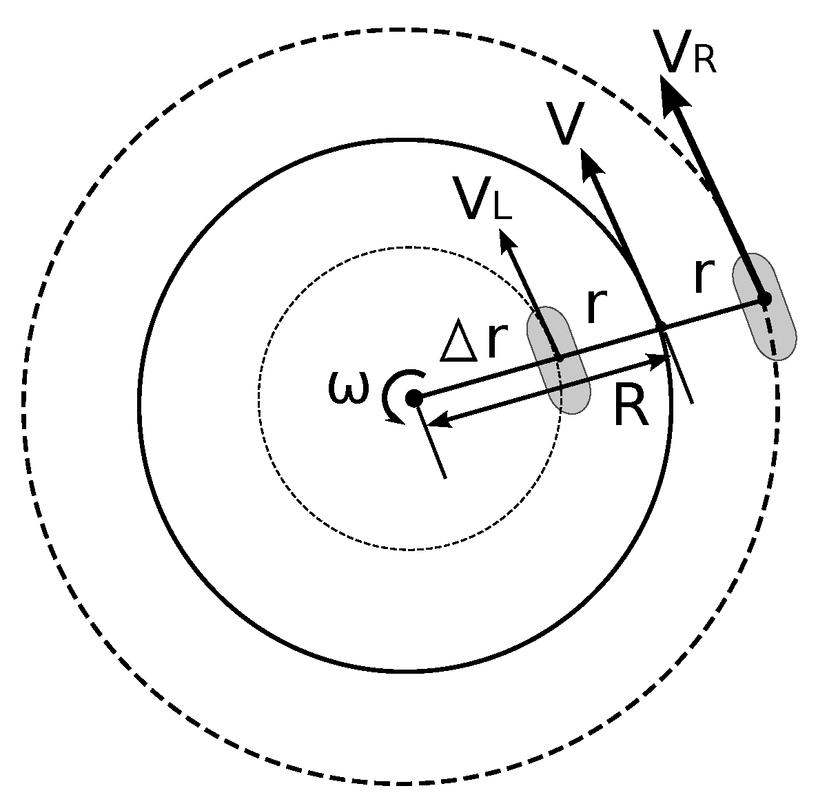
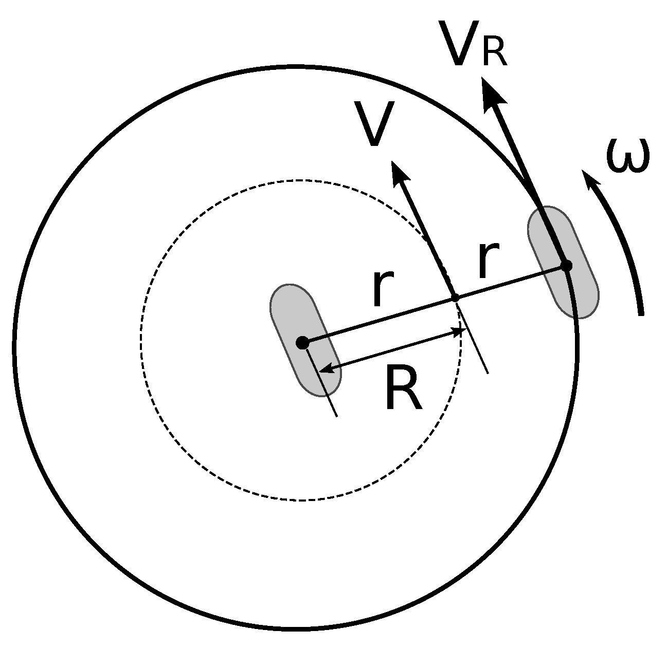
2.2. Fundamentals of Two-Wheeled Terrestrial Locomotion

Commonly, by varying the velocity at each of the wheels, the vehicle is able to move forwards or backwards, as well as turning clockwise (CW) or counterclockwise (CCW). If the power at each of the wheels can be accessed individually by means of separate control levers, then the maximum available power for the vehicle can be reached by displacing each of the levers at a maximum forward position, thus making it possible for it to follow a forward trajectory at full speed (i.e., both of the wheels at a 100% setting). In contrast, if just one of the wheels is fed with 100% of the power and the other wheel is left powerless, then the vehicle follows a tight circular trajectory by pivoting over one of its wheels. The tightest circular trajectory is achieved when the vehicle performs a turn-in-place movement [25,26], i.e., when both wheels receive 100% of the power but they have opposite rotation directions. In this case, the vehicle performs a rotation by pivoting over the center of chassis along the axis which binds both of the wheels.
To achieve a smooth circular trajectory, an arbitrary power reference (different from zero) must be sent to each of the wheels, thus allowing for the vehicle to follow a wider circular trajectory.
Figure 2 shows a simplified diagram of a two-wheeled vehicle. Here, V L and V R refer to the magnitude of the tangential velocities of the left and right wheels, respectively; (i.e., the velocity of each of the wheels regarding the ground). The magnitude V is the tangential velocity of the center point between the two wheels attached to the chassis. In this study, the magnitude of the velocities are assumed to be normalized, and they are considered to be proportional to the power delivered to each of the wheels. Moreover, the constant r indicates the distance between the center of the chassis and any of the wheels. If the magnitude V is needed, it can be obtained by averaging V L and V R , as shown by Mulana [14].
Figure 2 and Equation (1) show that the magnitude of the radius of curvature R comprises the length from the center of one the wheels to the center of the chassis r, with the distance from the rotation pivot to the center of the nearest wheel Δ r . It is assumed that the angular velocity ω and the radius of curvature R have a positive direction when the vehicle is turning CCW [14]. A particular case where the vehicle is turning CCW (using the left wheel as pivot) can be seen in Figure 3. Here, the radius of curvature R equals the distance r.
Notice that variable ω refers to the angular velocity of the vehicle regarding the ground, not the angular velocity of a wheel. In addition, consider that variables V L , V R , V, R, Δ r and ω depend on the joystick coordinates provided by the user; thus, they are functions of time. Similar schemes can be found in [27,28]; however, the proposed model prioritize the radius of curvature analysis as demonstrated in the following sections.
R = r + Δ r

2.3. Fundamentals of the Mathematical Norm

The mathematical two-norm (also called Euclidean norm) is well-known in basic mathematics and it is commonly associated with the calculus of minimum distances; for example, it can be used for estimating the magnitude of the hypotenuse of a right triangle if the length of the perpendicular sides are known. However, there exist in robotics problems described by an infinite number of solutions, which require a particular one to be selected for some type of optimization criterion. One possibility employs a type of optimization which minimizes the maximum magnitude of the solutions. This is the infinity-norm solution, also known as the minimum effort solution [29]. The general form of the mathematical norm is called the weighted L p norm, which has been used in robotics in [18]. When setting σ = 1 , we have the non-weighted case; in addition, when p = 2 , the Euclidean norm is obtained. If σ = 1 and p approaches infinity, then the mathematical norm approaches the infinity norm which is also equal to the maximum absolute value within the elements of x .
x ( p , σ ) = i = 1 n ( | x i | / σ i ) p 1 / p

3. The Mathematical Model for Two-Wheeled Locomotion

3.1. An Infinity-Norm Approach Applied to Joystick Kinematic Control

In two-wheeled vehicle joystick control, the goal is to transform a Cartesian coordinate; (i.e., a joystick position) into a motor actuation for each of the wheels.
By using the weighted mathematical norm, we are able to minimize the maximum value of the joystick coordinates when p approaches infinity. I addition, by choosing another value of p, we can variate the behavior of the motor actuation. Here, σ , has been chosen to be a constant for a particular value of p in order to make the motor command to be normalized to be suitable of being implemented in a Pulse Width Modulation Technique [30,31].
Theoretically, the power loss can be reduced to zero by using a normalized formula if an infinity-norm is used in the numerator along with an infinity root in the denominator (recall that a / b p = a p / b p ), as shown in Equations (3) and (4). However, it is important to consider that the processor memory will be overloaded when using infinite exponentials; instead, they have to be replaced by large exponentials. Here, x and y refer to the joystick position coordinates, and V R and V L are velocity commands which have been normalized by the structure of the formulas. Because in this particular study x remains positive, the absolute value bars are not needed for this coordinate. The form of the velocity command which does not make use of the p-norm was selected so that both of the wheels have the same value in a pure forward trajectory.
for y 0 V R = lim p x p + | y | p 2 p V L = lim p x 2 p
for y < 0 V R = lim p x 2 p V L = lim p x p + | y | p 2 p
Table 1 shows the maximum normalized velocities in the forward, CW and CCW trajectories for the left and right wheels as p is varied. In Table 1, it can be seen how the normalized velocity increases (and, consequently, the power) when p becomes greater. In the same table, it can be observed that, when using low-degree p exponentials, most of the power is lost by software. For example, when p = 1 , only 50 % of the power can be supplied to the wheels, whereas, when using p = 2 , only 70.7 % of the total power can be accessed. It can also be observed that, in the forward trajectory, both wheels receive the same amount of power, while, for the CW and CCW trajectories, the pivot wheel remains static, i.e., with zero velocity.

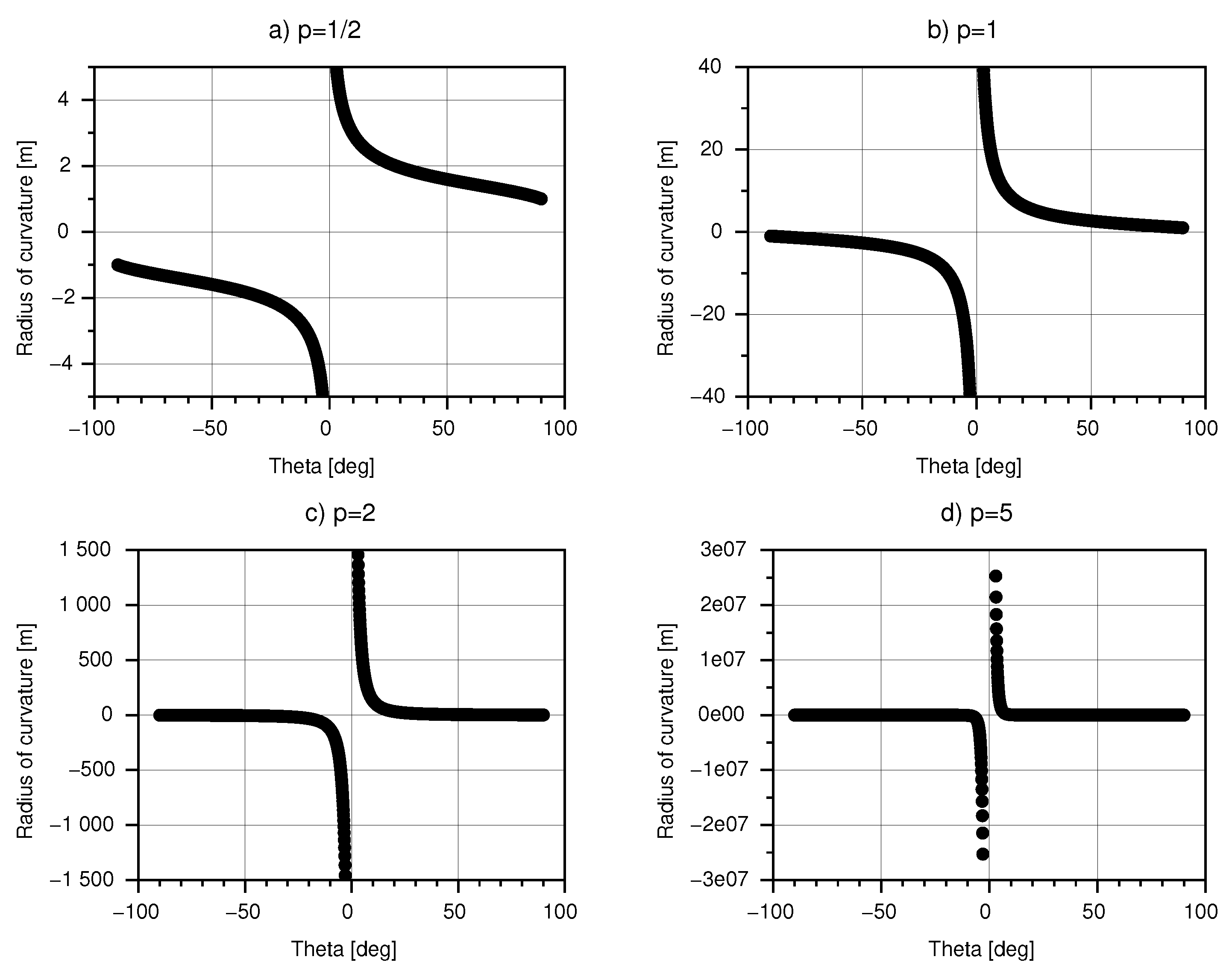
3.2. Analysis of the Radius of Curvature

In this subsection, a mathematical model is developed to analyze the change in trajectory of two-wheel vehicles when they are commanded by a joystick. The method is based in the radius of curvature traced by the vehicle when it navigates.
In Figure 2, it can be seen that:
V R = ω ( 2 r + Δ r )
and
V L = ω ( Δ r )
Because ω is equal for both wheels (including the chassis), we can substitute Equation (6) into Equation (5) to have Equation (7).
V R = V L Δ r ( 2 r + Δ r )
Substituting Equation (1) into Equation (7), we finally come to Equation (8), which provides the radius of curvature related to the left and right wheel velocities. As indicated by Chwa [32], because V R and V L are assumed to be normalized, their real values are not known beforehand, and thus, they must be estimated later in the design of the controller.
R = 2 r V L V R V L + r
From Equation (8), it can be seen that, when both velocities are equal, the denominator in the first term tends to zero, making the equation to approach infinity. Here, according to Cooper [5], a circular trajectory with a infinite radius of curvature means that, in fact, a rectilinear trajectory is being followed. If the vehicle performs a counterclockwise turn using the left wheel as pivot, then V L = 0 resulting in R = r , i.e., the radius of curvature is positive and it has a magnitude equal to the distance between the center of chassis and the left wheel (as shown in Figure 3). On the other hand, if the right wheel is taken as pivot, then V R = 0 resulting in R = r , that is, the vehicle is performing a clockwise turn with a radius of curvature equal to the magnitude of r.
According to Maulana [14], the velocity of the center of the chassis V can be obtained using Equation (9).
V = V R + V L 2
According to Nunes [10], Equation (10) gives the estimation of the rotation angle by integrating the angular velocity over time.
θ = t ω d t
Substituting Equation (9) into Equation (10), we have Equation (11), which can be used by position and orientation estimation algorithms.
θ = t V R d t

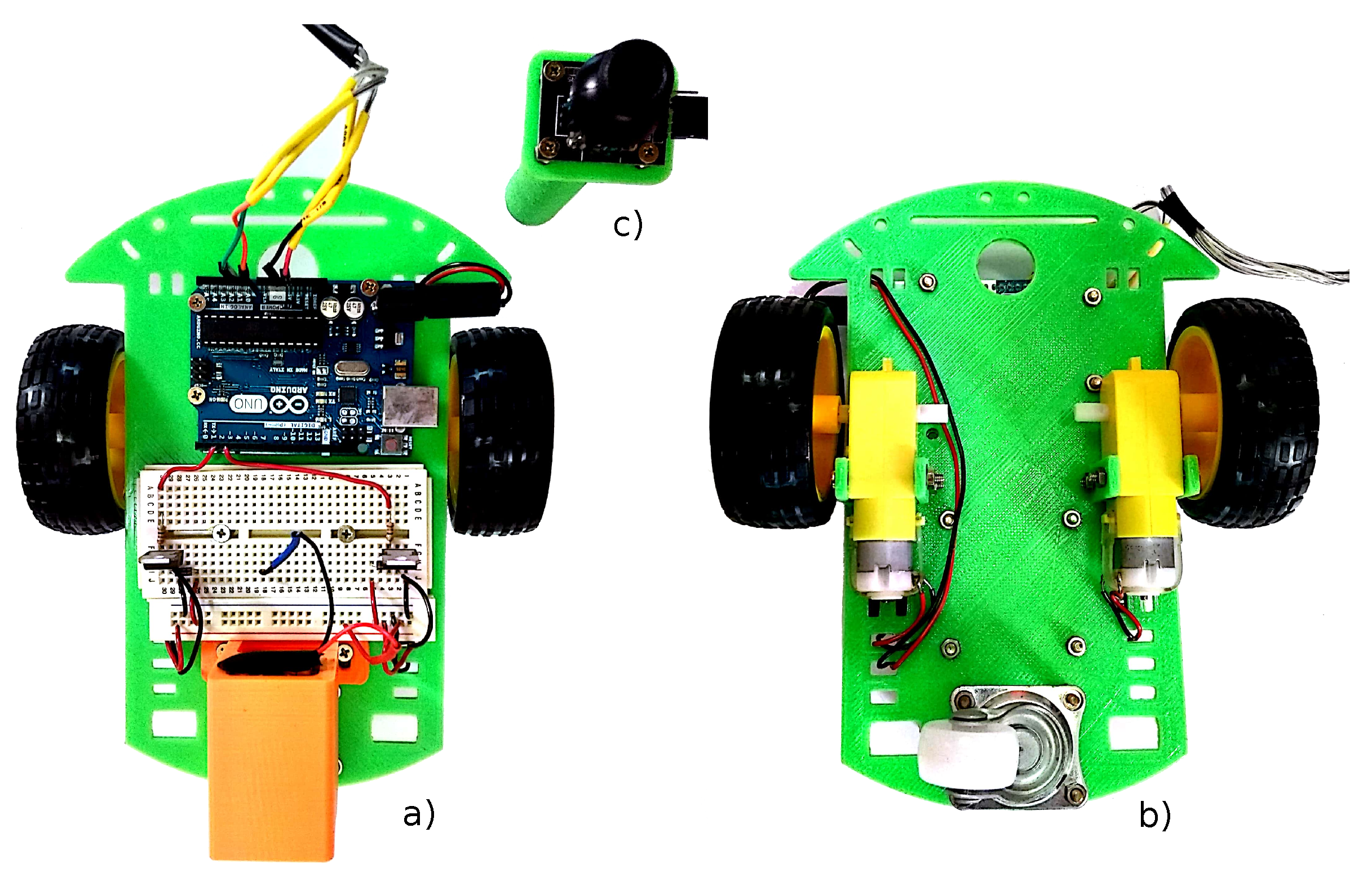
3.3. Experimentation Platform

To carry out the generation of trajectories, a tow-wheeled actuated robot was created using the 3D-printing technology (see Figure 4). An un-actuated third free-wheel was included only to provide support. The robot consists of an Arduino UNO micro-controller card, a joystick, a 9Vdc power supply, two Tip-41 BJT transistors, two 330 Ω resistors, two DC motors and two diodes. The joystick is provided with Vcc and GND terminals and the x-pot and the y-pot are connected to the analog ports A0 and A1 respectively. The digital ports 2 and 3 are connected to the base of each of the transistors to provide for a PWM signal to the motors. The diodes are connected in an anti-parallel fashion along the motor terminals to serve as inductive snubbers.
Inside the program, the signals coming from the potentiometers of the joystick are normalized and the velocity commands are calculated using Equations (3) and (4). Then, a PWM signal with a switching frequency of 50 ms and a duty cycle proportional to the calculated velocity magnitudes is provided to the DC motors.
The experimentation environment consists of two cones used as obstacles. The initial position of the robot is located at the lower right corner (see Figure 5), and the final position is located at the upper left corner. An erasable color marker is attached to the robot while it is guided by means of the joystick from the initial to the final position. This way, the trajectory is drawn over a white board.

4. Results

4.1. Simulation Results

Computer simulations were performed to know the behavior of the proposed joystick algorithm when used in the two-wheeled terrestrial locomotion; specifically, how the joystick coordinates affect the radius of curvature in Equations (3) and (4) as p increases. The numerical software package used in this work is SciLab [33].
Figure 6 shows a mapping of the radius of curvature when R j = 1 and Θ j moves from 90 to 90 when considering different values of p. For simulation purposes the distance from one of the wheels to the center of the chassis was considered to be equal to 1 meter; i.e., r = 1 . Figure 6a–d shows p equal to one-half, one, two, and five, respectively.
If the angle of the joystick is positive, then the radius of curvature is also positive because the vehicle is moving CCW. In contrast, if the angle of the joystick is negative, then the radius of curvature is also negative because the vehicle is moving CW.
Figure 6 shows that, when the Θ j approximates to zero degrees (i.e., the joystick displacement is aligned with the X-axis), the radius of curvature tends to infinity. Both positive and negative radii of curvature imply that a forward trajectory is being followed; however, in the case of an infinite negative radius of curvature, the theoretical pivot from which the radius of curvature is measured is located at the right side of the vehicle.
In Figure 6, it is important to notice that, despite the increase in traction power when p is incremented, the vehicle losses its capacity to follow a soft turn when switching from a forward trajectory to a circular one, i.e., either the vehicle tends to go in a forward direction (for values of Θ j close to 0 ), or to follow a pivoted turn. On the other hand, when p is decreased, then the ability to a perform smooth trajectory is incremented; however, the traction power capability decreases.
Table 2 shows the radii of curvature for different values of p when R j = 1 . In this table, it is easy to see that, if the angle of the joystick Θ j has a value of 90 (a CCW turn is commanded), then the radius of curvature R has the same dimension as the distance from the left wheel to the center of the chassis, i.e., R = r = 1 . A similar situation arises when Θ j = 90 , where the vehicle is turning clockwise and R = 1 .
Figure 7 shows the polar plots of the normalized velocities of the left wheel V L (in color blue), and the right wheel V R (in color red) regarding the angle of the joystick Θ j when R j = 1 . The data in Table 1 can be corroborated in Figure 7. For example, it can be seen that, if the angle of the joystick is 0 , then the magnitude of the normalized velocities V L and V R for p = 1 / 2 are 0.25; similarly, for p = 1 , V L = V R = 0.5 .

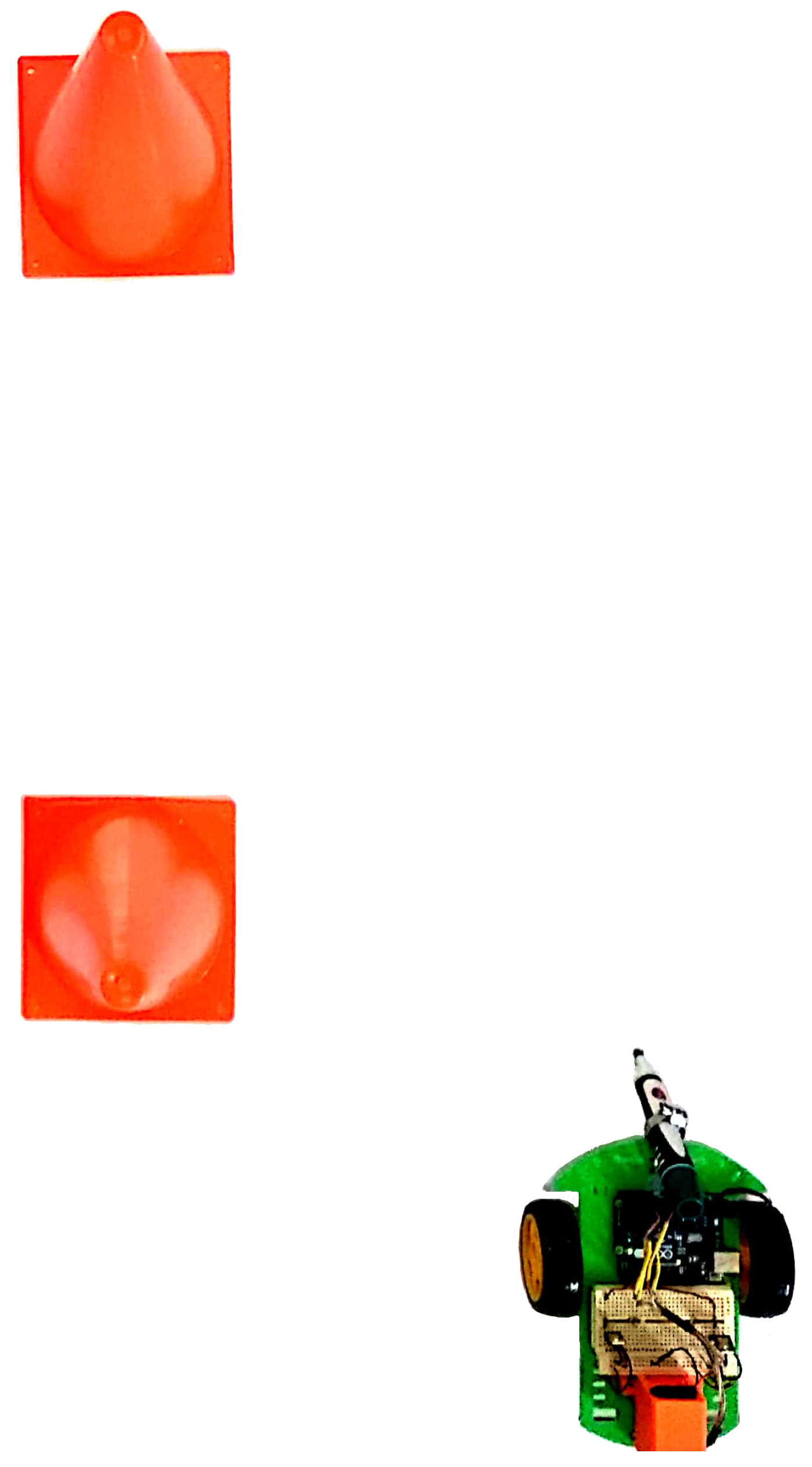
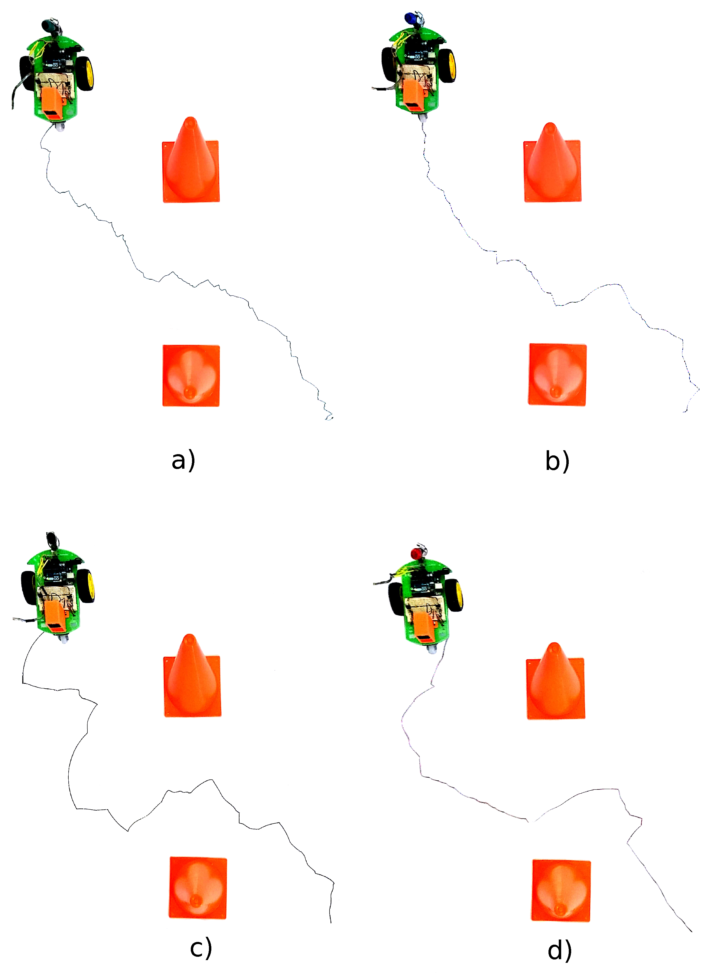
4.2. Experimental Results

Figure 8 shows the generated trajectories using different values for parameter p. It can be observed that, as predicted by Equations (3) and (4), a softer trajectory is produced for small values of p, i.e., the trajectory adjustments produced by the joystick can be finer. As parameter p increases, more power is delivered to the wheels, and thus, the acceleration is greater and longer traces are produced as a consequence.
As shown in Figure 6, a trajectory can be considered soft when the robot is capable of following turn commands. If we assume real tangential velocities to be k · V R and and k · V L for the right and the left wheels (where the constant k is an unknown proportional parameter), and if we substitute these values into Equation (8) instead of the terms V R and V L , then the parameter k is eliminated; thus, the radius of curvature described by Equation (8) only depends on the distance r and the normalized velocities V R and V L . Taking advantage of this fact and considering r = 6.5 cm for the robot shown in Figure 8, Table 3 shows the radius of curvature for a joystick angle of Θ j = 45 and a magnitude of R j = 1 (i.e., x = 0.707 and y = 0.707 ). In this table, it can be observed that, despite the joystick intension for the robot to perform a turn, the robot tries to follow a rectilinear trajectory as the parameter p is increased because both velocities ( V R and V L ) tend to be equal.
Regarding the power management, Table 4 shows how the wheels receive more power as parameter p is increased. The voltage across the terminals of one of the wheels was measured when the joystick is completely displaced towards the positive direction of the X-axis. Because joystick measurements are normalized, in this case Θ j = 0 and R j = 1 , i.e., both wheels receive the same amount of power. The current was measured in series with the battery, so by neglecting the power consumed by the microcontroller, the power measurement shown in last column of Table 4 corresponds to the two motors. Figure 9 shows the case when p = 1 ; here, a voltage of 6.83 V times a current of 0.32 A results in 2.18 watts.

5. Conclusions and Future Work

In the present study, we can conclude that a joystick algorithm may have an important effect in the trajectory smoothness and traction power of two-wheeled vehicles. In our particular case, despite the increment in traction power as p increased, the vehicle became less sensitive at executing smooth trajectory modifications. However, because the variable term p is not fixed, it can be set to a low degree to achieve smooth trajectory changes by ceding traction power.
In this work, a mathematical model based in the radius of curvature has been developed to analyze the effect of the proposed joystick algorithm regarding the two-wheeled locomotion. Computer simulations were performed to show the effect of varying the parameter p. An important observation is that, for our particular case, the infinite radii of curvature, whether positive or negative are part of the same forward trajectory. Another consequence of this study is that, if a position and orientation analysis is needed, an integral analysis over the tangential velocity of the center of the chassis and the radius of curvature can be performed, provided that the left and the right tangential velocities of the wheels V L and V R are known, which is possible by using the algorithms proposed in this work. Regarding the experimentation results, it was confirmed that smaller values of parameter p produced finer trajectories but subtracted wheel power. In contrast, increasing values of p produced greater traction power, and, thus, larger robot acceleration but less maneuverability. However, this parameter could be adjusted according to specific required needs. Surely, circumstances such as wheel-to-ground slip, mechanical-part friction, power supply charge, human expertise, and robot architecture have a decisive impact over the experiment results.
As future work, the following opportunity areas remain: The study of the backwards movement and the inclusion of a regulatory controller (i.e., PID, optimal, state-feedback, sliding mode, etc.). The regulatory controller should correct the position and the orientation as well as work along with the proposed kinematic control. Here, it is believed that the knowledge we now have in advance about the vehicle’s trajectory regarding the wheel velocities should minimize the manipulation action.

Author Contributions

A.S. conceived the idea, implemented the mathematical procedures, performed the simulations, and wrote the paper. Y.D. reviewed the mathematical form of the equations and looked for a suitable journal. R.S. and L.C.F. analyzed and reviewed the paper structure and validated the data. C.H.-S. and P.E.-R. carried out the literature review.

Funding

This research work received no funding.

Acknowledgments

The authors would like to thank the support for the open-access publishing costs covered by the Center for Robotics and Intelligent Systems (CRIS) and the National Laboratory for Robotics CONACyT-ITESM, located at Instituto Tecnológico y de Estudios Superiores de Monterrey (ITESM); Eugenio Garza Sada 2501, Monterrey, N.L., México, Zip Code 64849.

Conflicts of Interest

The authors declare no conflict of interests.

References

  1. Zhao, H.; Duan, X.; Yang, G. Kinematics and dynamics modeling of a small mobile robot with tracked locomotion mode. In Proceedings of the 2010 IEEE International Conference on Robotics and Biomimetics (ROBIO), Tianjin, China, 14–18 December 2010; pp. 1276–1280. [Google Scholar]
  2. Fujiya, T.; Mikami, S.; Nakamura, T.; Hama, K. Locomotion method of a rescue robot with multi-legs and Omni-directional wheels. In Proceedings of the 2014 13th International Conference on Control Automation Robotics & Vision (ICARCV), Singapore, 10–12 December 2014; pp. 1627–1630. [Google Scholar]
  3. Wang, X.; Wang, X.; Wang, H.; Lu, L.; Yu, H.; Vladareanu, L.; Melinte, D.O. Dynamic analysis for the leg mechanism of a wheel-leg hybrid rescue robot. In Proceedings of the 2014 UKACC International Conference on Control (CONTROL), Loughborough, UK, 9–11 July 2014; pp. 504–508. [Google Scholar]
  4. Van Sickle, D.; Cooper, R.; Ster, J. Wheelchair virtual joystick interface. In Proceedings of the IEEE 17th Annual Conference on Engineering in Medicine and Biology Society, Montreal, QC, Canada, 20–23 September 1995; Volume 2, pp. 1175–1176. [Google Scholar]
  5. Cooper, R.A.; Jones, D.K.; Fitzgerald, S.; Boninger, M.L.; Albright, S.J. Analysis of position and isometric joysticks for powered wheelchair driving. IEEE Trans. Biomed. Eng. 2000, 47, 902–910. [Google Scholar] [CrossRef] [PubMed]
  6. Haas, E.C.; Kunze, M. The effect of a vehicle control device on driver performance in a simulated tank driving task. In Proceedings of the First International Driving Symposium on Human Factors in Driving Assessment, Training and Vehicle Design, Aspen, CO, USA, 14–17 August 2001; pp. 143–146. [Google Scholar]
  7. Fattouh, A.; Sahnoun, M.; Bourhis, G. Force feedback joystick control of a powered wheelchair: Preliminary study. In Proceedings of the 2004 IEEE International Conference on Systems, Man and Cybernetics, The Hague, The Netherlands, 10–13 October 2004; Volume 3, pp. 2640–2645. [Google Scholar]
  8. Rabhi, Y.; Mrabet, M.; Fnaiech, F.; Gorce, P. Intelligent joystick for controlling power wheelchair navigation. In Proceedings of the 2013 3rd International Conference on Systems and Control (ICSC), Algiers, Algeria, 29–31 October 2013; pp. 1020–1025. [Google Scholar]
  9. Rabhi, Y.; Mrabet, M.; Fnaiech, F. Optimized joystick control interface for electric powered wheelchairs. In Proceedings of the 2015 16th International Conference on Sciences and Techniques of Automatic Control and Computer Engineering (STA), Monastir, Tunisia, 21–23 December 2015; pp. 201–206. [Google Scholar]
  10. Nunes, W.R.B.M.; da Silva, N.; Covacic, M.R.; Junior, A.P.L. 3ph High Efficiency Induction Motors with IFOC Applied to a Wheelchair by Joystick. IEEE Latin Am. Trans. 2016, 14, 2041–2051. [Google Scholar] [CrossRef]
  11. Xia, C.; Zhang, C. Power management strategy of hybrid electric vehicles based on quadratic performance index. Energies 2015, 8, 12458–12473. [Google Scholar] [CrossRef]
  12. Ali, A.M.; Söffker, D. Towards Optimal Power Management of Hybrid Electric Vehicles in Real-Time: A Review on Methods, Challenges, and State-Of-The-Art Solutions. Energies 2018, 11, 476. [Google Scholar] [Green Version]
  13. Zhang, X.; Mi, C. Vehicle Power Management: Modeling, Control and Optimization; Springer Science & Business Media: London, UK, 2011. [Google Scholar]
  14. Maulana, E.; Muslim, M.A.; Zainuri, A. Inverse kinematics of a two-wheeled differential drive an autonomous mobile robot. In Proceedings of the Electrical Power, Electronics, Communications, Controls and Informatics Seminar (EECCIS), Malang, Indonesia, 27–28 August 2014; pp. 93–98. [Google Scholar]
  15. Tsai, M.C.; Hsueh, P.W. Synchronized motion control for 2D joystick-based electric wheelchair driven by two wheel motors. In Proceedings of the 2012 IEEE/ASME International Conference on Advanced Intelligent Mechatronics (AIM), Kaohsiung, Taiwan, 11–14 July 2012; pp. 702–707. [Google Scholar]
  16. Rabhi, Y.; Mrabet, M.; Fnaiech, F. Development of a New Intelligent Joystick for People with Reduced Mobility. Appl. Bionics Biomech. 2018, 2018. [Google Scholar] [CrossRef]
  17. Yoon, H.; Seo, H.H.; Park, Y.W.; Choi, H.T. A new minimum infinity-norm solution: With application to capacity analysis of spacecraft reaction wheels. In Proceedings of the American Control Conference (ACC), Chicago, IL, USA, 1–3 July 2015; pp. 1241–1245. [Google Scholar]
  18. Hyun, N.S.P.; Vela, P.A.; Verriest, E.I. A New Framework for Optimal Path Planning of Rectangular Robots Using a Weighted L_p Norm. IEEE Robotics Autom. Lett. 2017, 2, 1460–1465. [Google Scholar] [CrossRef]
  19. Villarreal, B.L.; Gordillo, J.L. Directional aptitude analysis in odor source localization techniques for rescue robots applications. In Proceedings of the 2011 10th Mexican International Conference on Artificial Intelligence (MICAI), Aguascalientes, Mexico, 4–10 November 2011; pp. 109–114. [Google Scholar]
  20. Babazadeh, R.; Khiabani, A.G.; Azmi, H. Optimal control of Segway personal transporter. In Proceedings of the 2016 4th International Conference on Control, Instrumentation, and Automation (ICCIA), Qazvin, Iran, 27–28 January 2016; pp. 18–22. [Google Scholar]
  21. Li, W.; Liu, B.; Kosasih, P.B.; Zhang, X. A 2-DOF MR actuator joystick for virtual reality applications. Sens. Actuators A Phys. 2007, 137, 308–320. [Google Scholar] [CrossRef]
  22. Nasif, S.; Khan, M.A.G. Wireless head gesture controlled wheel chair for disable persons. In Proceedings of the Humanitarian Technology Conference (R10-HTC), 2017 IEEE Region 10, Dhaka, Bangladesh, 21–23 December 2017; pp. 156–161. [Google Scholar]
  23. Fortuna, L.; Muscato, G. A roll stabilization system for a monohull ship: modeling, identification, and adaptive control. IEEE Trans. Control Syst. Technol. 1996, 4, 18–28. [Google Scholar] [CrossRef]
  24. Karvinen, T.; Karvinen, K.; Valtokari, V. Make: Sensors. Projects and Experiments to Measure the World with Arduino and Raspberry Pi; Marker Media: Sebastopol, CA, USA, 2014. [Google Scholar]
  25. Abdolmaleki, A.; GhasemAghaee, N.; Reza, M.; Monadjemi, A. Robust humanoid turning-in-place using fourier series and genetic algorithm. In Proceedings of the 2011 4th International Conference on Modeling, Simulation and Applied Optimization (ICMSAO), Kuala Lumpur, Malaysia, 19–21 April 2011; pp. 1–5. [Google Scholar]
  26. Said, A.; Rodriguez-Leal, E.; Soto, R.; Gordillo, J.; Garrido, L. Decoupled closed-form solution for humanoid lower limb kinematics. Math. Prob. Eng. 2015, 2015. [Google Scholar] [CrossRef]
  27. Jia, Q.; Cao, X.; Sun, H.; Song, J. A novel design of a two-wheeled robot. In Proceedings of the Conference on Industrial Electronics and Applications, ICIEA 2007, Harbin, China, 23–25 May 2007; pp. 1226–1231. [Google Scholar]
  28. Cho, S.K.; Jin, H.Z.; Lee, J.M.; Yao, B. Teleoperation of a mobile robot using a force-reflection joystick with sensing mechanism of rotating magnetic field. IEEE/ASME Trans. Mech. 2010, 15, 17–26. [Google Scholar]
  29. Gravagne, I.A.; Walker, I.D. On the structure of minimum effort solutions with application to kinematic redundancy resolution. IEEE Trans. Robot. Autom. 2000, 16, 855–863. [Google Scholar] [CrossRef] [Green Version]
  30. Mohan, N.; Undeland, T.M. Power Electronics: Converters, Applications, and Design; John Wiley & Sons: Hoboken, NJ, USA, 2007. [Google Scholar]
  31. Said, A.; Davizón, Y.A.; Espino-Román, P.; Rodríguez-Said, R.; Hernández-Santos, C. Automatic Frequency Identification under Sample Loss in Sinusoidal Pulse Width Modulation Signals Using an Iterative Autocorrelation Algorithm. Symmetry 2016, 8, 78. [Google Scholar] [CrossRef]
  32. Chwa, D. Robust Distance-Based Tracking Control of Wheeled Mobile Robots Using Vision Sensors in the Presence of Kinematic Disturbances. IEEE Trans. Ind. Electron. 2016, 63, 6172–6183. [Google Scholar] [CrossRef]
  33. Group, E. SciLab [Numeric Calculus Software]. Available online: http://www.scilab.org/ (accessed on 15 July 2018).
Figure 1. Geometrical parameters of the joystick.
Electronics 07 00164 g001
Figure 2. Geometrical disposal the variables used in the two-wheeled simplified model.
Electronics 07 00164 g002
Figure 3. Performing a CCW turn with the left wheel as pivot.
Electronics 07 00164 g003
Figure 4. (a) Front; and (b) reverse sides of the real experimentation platform; and (c) the joystick controller.
Electronics 07 00164 g004
Figure 5. Initial position of the robot at the experimentation environment.
Electronics 07 00164 g005
Figure 6. Effect of the increase of parameter p in the radius of curvature.
Electronics 07 00164 g006
Figure 7. Polar plots of the magnitude of V L (in blue) and the magnitude of V R (in red) regarding the angle Θ j .
Electronics 07 00164 g007
Figure 8. Generated trajectories using: (a) p = 1 / 2 ; (b) p = 1 ; (c) p = 2 ; and (d) p = 5 .
Electronics 07 00164 g008
Figure 9. Electric power delivered to one of the wheels when p = 1 and the joystick is displaced completely in the positive direction of the X-axis.
Electronics 07 00164 g009
Table 1. Maximum normalized velocities.
ForwardCWCCW
( x = 1 , y = 0 ) ( x = 0 , y = 1 ) ( x = 0 , y = 1 )
p V L V R V L V R V L V R
1 / 2 0.250.250.25000.25
10.50.50.5000.5
20.7070.7070.707000.707
30.7930.7930.793000.793
50.870.870.87000.87
80.9170.9170.917000.917
200.9650.9650.965000.965
1000.9930.9930.993000.993
Table 2. Radius of curvature R for different joystick angles when R j = 1 .
Θ j p = 1 / 2 p = 1 p = 2 p = 5
90 −1−1−1−1
60 −1.45−2.15−3−3.65
30 −1.95−4.46−13.92−160.83
3 −4.91−39.16−1458.35−25,294,220
3 4.9139.161458.3525,294,220
30 1.954.4613.92160.83
60 1.452.1533.65
90 1111
Table 3. Radius of curvature R when the angle and the magnitude of the joystick are θ j = 45 and R j = 1 , respectively, when parameter p is increased.
p V R V L R [cm]
1 / 2 0.7070.17623.8080
10.7070.35332.4630
20.7070.49950.6870
50.7070.615106.402
Table 4. Electric power (measured in watts) delivered to one of the wheels when the joystick is displaced completely in the positive direction of the X-axis.
pVoltage [V]Current [A]Power [W]
1 / 2 5.500.281.54
16.830.322.18
27.200.342.44
58.000.372.96

