1. Introduction
The biomimetic approach has become a very popular topic with developing new technologies inspired by nature. Investigation of existing systems in nature and adapting this technology from nature to engineering fields are called biomimetic. The aim of the biomimetic design is to bring innovative solutions to engineering problems by imitating living forms and improving existing systems. Nowadays, this significant approach is frequently utilized in many different fields, such as robotics, artificial intelligence, nano-technology, defense systems, healthcare, etc. [
1,
2,
3,
4,
5]. When underwater living forms are examined, a biomimetic design seems to be an appropriate approach for an Autonomous Underwater Vehicle (AUV). It is well known that fish are the best swimmers with their high maneuverability, fast swimming and sudden acceleration in nature. A fish-like underwater robot, which has flexible tail mechanism, can swim faster and more quietly with lower consumption and higher maneuverability in water, where a conventional propeller AUV cannot reach [
6,
7,
8,
9]. These kinds of robots, namely robotic fish, are preferred for underwater exploration, observation andresearch purposes, especially where maneuverability is required [
10]. Considering these advantages, a robotic fish design provides versatile solutions for various different marine applications, such as examination of underwater resources, determination of pollution, observation of living forms, survey of submerged areas, fault detection in electricity or oil pipelines, coastline security and military missions [
10,
11,
12,
13].
Important factors in the design of a biomimetic robotic fish are primarily the swimming modes and the body structure of the fish. A detailed examination of fish helps us learn about providing significant limitations and constraints of any biological property before designing a robotic fish [
14,
15]. A bio-inspired robotic fish uses undulatory and/or oscillatory body motions [
16,
17]. In ichthyology, more than 85% of fish swim by bending their bodies and/or caudal fins (BCF) and about 15% of fish swim by median and/or pectoral fins (MPF). Also, Carangiform swimming mode is the most common BCF locomotion type of the fish which uses undulatory motions [
18,
19,
20]. These biological properties indicate that BCF type Carangiform robot model is an appropriate approach for AUV design.
In the literature, there are a lot of robotic fish designs and manufacturing with several properties. There are two basic approaches in robotic fish design. First is the biomimetic design which has certain requirements such as a tail with the size and number of joints to provide body travelling wave, and the ability to stay at a certain depth with the control of the center of gravity [
15,
21,
22]. The second design approach uses only the movement effects of fish, but it is not physically inspired by real fish. Malec et al. designed three-link CyberFish by focusing on BCF-like locomotion. The prototype was produced by using acrylic, rubber, aluminum and stainless steel. In the referred work, the angle of the pectoral fins associated with the servomotor is changed to provide up-down motions as sharks [
23]. Masoomi et al. used 3D-printing technology in order to construct the tuna-like robotic fish with a main body and flexible tail mechanism. The robot surface was covered with epoxy to provide waterproofness [
24]. Wang et al. designed a robotic dolphin with fiberglass-reinforced plastic [
14]. Kodati et al. developed Ostaciiform-type boxfish which has the pectoral and caudal fins [
25]. Phamduy et al. designed a miniature robotic fish prototype to investigate animal-robot interaction studies. They used 3D-printing technology to manufacture the robot prototype [
26]. Afolayan et al. proposed a fish-like underwater robot with a body in a thin plastic film manufactured by using a vacuum packaging machine. The prominent features of this work is that although it is not a biomimetic design, it has a high pressure resistance and is lightweight [
27]. Marchese et al. designed and fabricated a soft robotic fish with rapid motion ability. In this work, they focused on rapid escape responses of the prototype [
28]. Chowdhury and Panda proposed to product a robotic fish with undulatory swimming behaviors. In this work, biological vertebrate fish swimming was integrated to the mobile underwater vehicle [
29]. Huang et Al. suggested a solution to minimize a swimming robot by using polymer film works as motor. A soft micro robot was fabricated with this type of remote light-driven approach, and it held future promise in the areas of micro-machines and robots [
30].
In this study, a biomimetic design and manufacturing of the intelligent robotic fish prototype (i-RoF) is proposed for real-world exploration and survey missions. These important missions require high swimming ability and cruise straight swimming speed. Therefore, important key issues related to three-dimensional swimming abilities and biomimetic design are emphasized and detailed in this paper. The robotic fish mimics BCF-type Carangiform swimming modes with a propulsive tail mechanism driven by servo motors. An anterior rigid torpedo-shaped body is designed for housing the electronics, sensors and Center of Gravity (CoG) control mechanism. CoG control mechanism successfully provides up-down motion abilities. The locomotion control is adapted based on Central Pattern Generator (CPG) to generate robust, smooth and rhythmic oscillatory swimming patterns. The proposed CPG model is inspired by Lamprey spinal cord to ensure biomimetic design and intelligent control. In this respect, the proposed robotic fish prototype is biomimetic in terms of both design and control. Performance analyses of the robotic fish in an experimental pool environment are performed to verify high swimming abilities of the robot.
The paper provides seven main sections. The literature review about design and manufacturing of fish-like robots are presented in
Section 1. Design procedure of the robotic fish prototype is given in
Section 2. The proposed mechanical system design of the prototype is detailed in
Section 3. Electronic system design is also given in
Section 4.
Section 5 describes the established Lamprey CPG model for locomotion control. In
Section 6, three-dimensional motion performances of the robotic fish with experimental results are presented. Finally, conclusions are given in
Section 7.
2. Design Procedure of the Robotic Fish Prototype
A detailed investigation of the whole biological specifications of a real fish is necessary to identify the main criteria of bio-inspired approach of the robotic fish. In this way, structural constraints and capabilities of the biological features are determined before prototype implementation. Most fish generate thrust force by bending their bodies into a lateral propulsive wave which passes from the fish body through the opposite direction. These swimming gaits are classified under BCF locomotion. BCF gaits contain undulatory and oscillatory propulsions. BCF locomotion can be categorized into four basic subgroups as Anguilliform, Subcarangiform, Carangiform and Thunniform according to the wavelength and amplitude of the propulsive wave [
16,
31,
32]. Carangiform locomotion, the most common type of BCF, exhibits significant swimming actions such as undulatory swimming motions, high speed performance, low noise, fast start, rapid turning and high accelerations. These specifications of Carangiform locomotion provide an appropriate solution for biomimetic design of AUVs [
32,
33,
34,
35].
In this study, the design procedure, content and implementation of the robotic fish i-RoF which is manufactured by the authors of this paper at University of Firat by working on since 2015 are presented. The prototype inspired by Carangiform locomotion has two primary features which are fish-like swimming ability with its novel propulsive tail mechanism design and autonomous three dimensional motion with its surrounding sensors and intelligent control unit.
The following eight basic characteristics are considered for the designed biomimetic robotic fish prototype:
The robotic fish inspired by Carangiform fish has a biomimetic design and is able to swim by imitating the swimming motion of a real carp fish.
The body shape of the robotic fish is designed as torpedo-shaped to reduce the hydrodynamic frictional forces and the outer surface of each component is covered with materials that reduce the vortex effects.
The components of multiple parts of the robot are designed as modular. Thus, the necessary interventions are relatively easy at the time of assembly and breakdown.
All of the mechanical components are provided to be waterproof. Thus, experimental studies of the prototype can be easily performed in water.
The CoG is determined in the same direction as the buoyancy center and slightly below. Thus, the roll effect of the robotic fish in water is stabilized at about 0 degrees.
Robotic fish have three-dimensional motion ability and the ability to stand on the water surface without applying thrust force to the robot. It is provided by ensuring the density of the robot is so close to 1000 g/m3 which is the density of water.
Robotic fish has a biomimetic and intelligent locomotion control structure that can perform complex control algorithms using CPG and Fuzzy Logic approaches.
Robotic fish can swim autonomously by avoiding obstacles in three-dimensional space.
3. Mechanical Design of the Prototype
The robotic fish prototype consists of five basic components including anterior rigid main body, two-link tail mechanism driving by servo motors, control unit performing CPG model, the front sight unit and a flexible caudal fin. Tail links driven by high-powered servo motors and one flexible caudal fin fixed to peduncle are designed to generate a body travelling wave of the prototype. These links connected to each other in the shape of a series chain structure produce the thrust force needed for swimming motions.
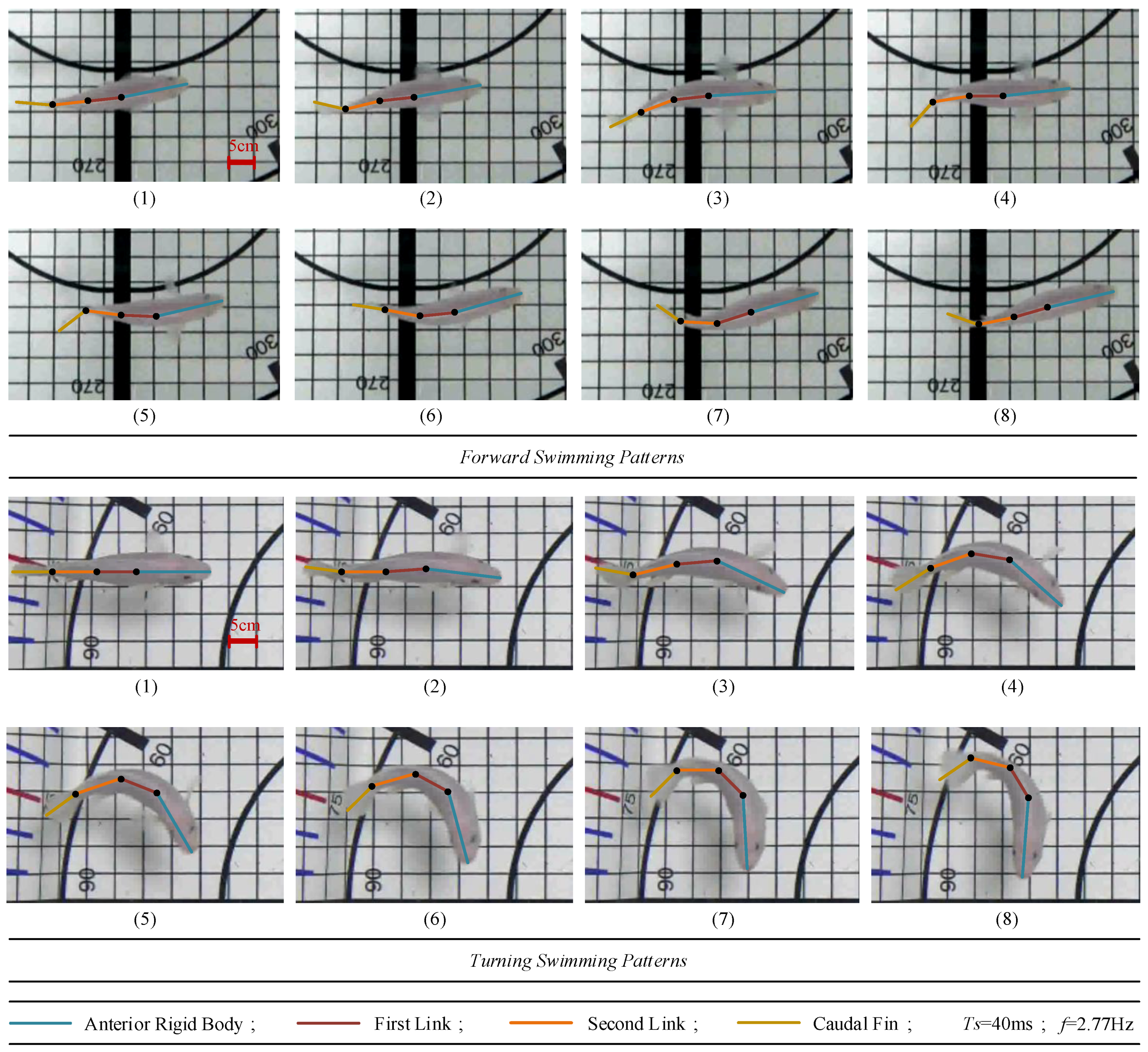
The dimensions and characteristics of all parts are determined considering the body measurements of a real Carangiform fish. In order to analyze the two-link chain structure of a fish model, three points are defined to verify link lengths on forward and turning swimming patterns of the real fish as seen in
Figure 1. The fact that the robotic fish has as many joints as possible allows the real fish motions to be imitated more easily [
15,
21,
22,
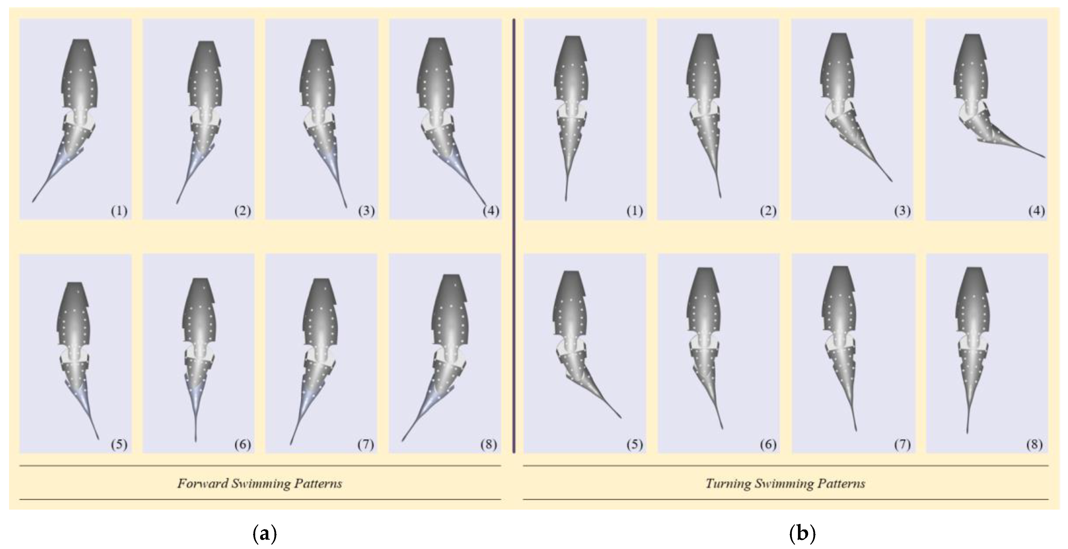
36]. However, with the proposed two-link tail mechanism, a simpler and more practical design can be achieved. The link lengths are determined by analyzing 50 swimming patterns for forward and turning swimming modes. The obtained link lengths of three basic components of the real fish are adapted to prototype model. The concept design of the robotic fish in SimMechanics environment for forward and turning swimming patterns is presented in
Figure 2.
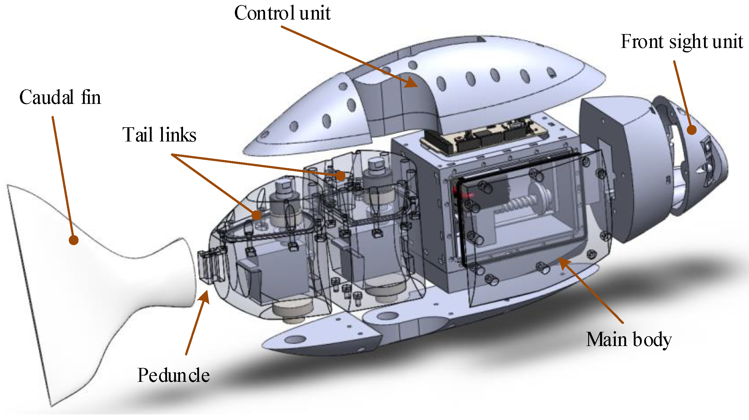
The detailed configuration of the robotic fish prototype with modular parts is illustrated in
Figure 3. It can be seen that there are the main body with CoG control mechanism and battery, two tail links driving with servo motors, control unit, front sight unit with distance sensors and a flexible caudal fin. The distribution of all the components on the prototype is carefully realized to balance the lift force and weight of the robotic fish.
All components of the robotic fish are designed in proportional dimensions and the 3D solid model of each component is created in the SolidWorks environment. In the production phase, the STL formats of the prepared solid models are transferred to the Voxelizer program. These files are converted to voxel format in Voxelizer environment and layer, print and support point settings are configured.
Each part of the prototype which is designed and modeled in 3D with SolidWorks environment is produced by using PLA in 3D-printing technology. The flexible caudal fin is also produced by using mold silicone. All parts are covered with epoxy resin to prevent possible leakage from the micro pores formed in the production process. After the assembly phase, the outer surface is covered with synthetic paint to prevent leakages that may be caused by capillary cracks during assembly.
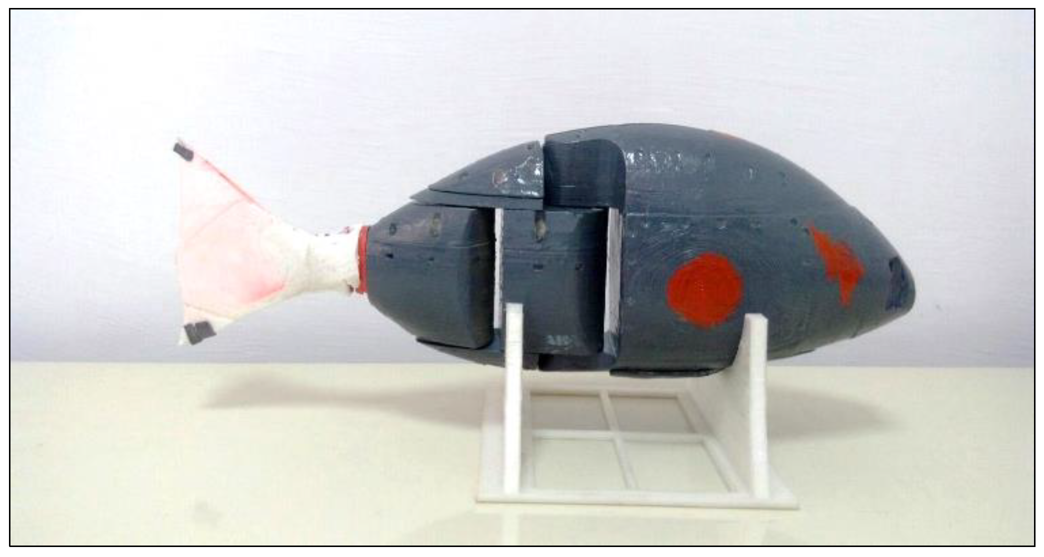
A CoG control mechanism is designed to perform three-dimensional motion in the water. The developed robotic fish prototype can swim autonomously in the water and it can perform the desired behavior with the commands sent by user. The Bluetooth 2.0 connection is adapted for the wireless communication system between the robotic fish and user computer, and the wireless communication distance is approximately 10 m. In addition, programming and charge connections of the prototype are performed with USB port. Robotic fish should be able to perceive static and/or dynamic obstacles in the environment as they move through the water. For this reason, three Sharp infrared distance sensors are placed in the left, right and front of the robotic fish. The Prop Shield 10-DoF IMU motion sensor is available for simultaneous angular and linear positions, speed, acceleration, and altitude and temperature data during swimming. 7.4 V 1350 mAh Lithium Polymer (Li-Po) rechargeable battery is used for the power supply of the servomotors and the electronic control system. The detailed technical characteristics of the developed robotic fish prototype are given in
Table 1, and a photo image of the developed prototype is also presented in
Figure 4.
The robotic fish prototype is approximately 500 mm long, 76 mm wide and 215 mm high. The prototype mass is also approximately 3.1 kg.
3.1. Propulsive Two-Link Tail Mechanism
The thrust force required for the motion of the robotic fish is provided by designed two-link tail mechanism. Each link consists of three basic components: Hitec D954SW RC servo motor, servo motor housing and top housing. The mechanical configuration of the designed second link is given in
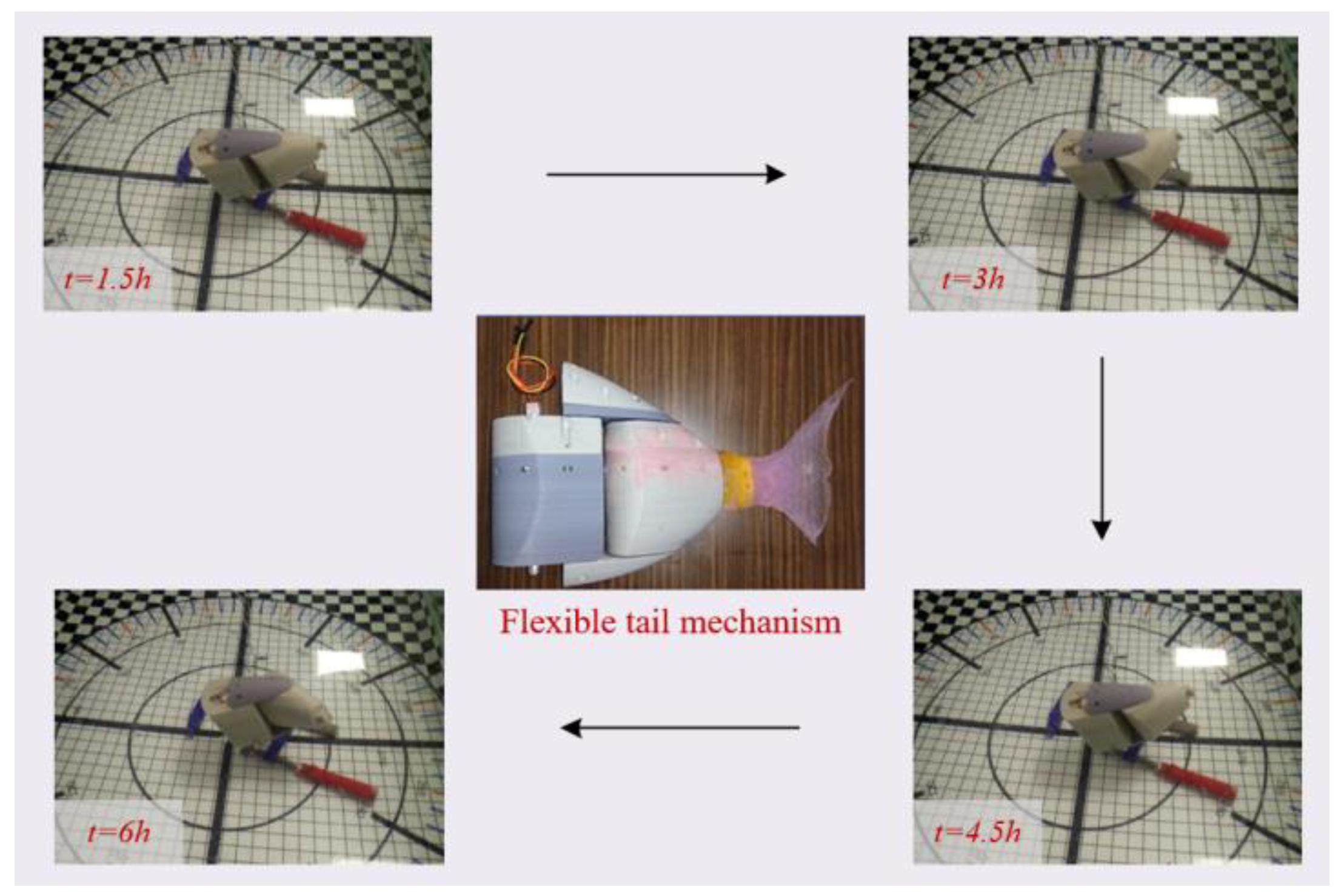
Figure 5. Each servomotor is fixed to the motor housing and an aluminum 25T upper shaft is mounted to the motor gear shaft to transmit the turning motion. A sealing felt and a single row fixed ball bearing are mounted on the upper shaft seat so that the motor upper shaft can perform its turning motion in its vertical axis direction and it can be sealed. Grease oil is used between the shaft and the ball bearing in order to increase the waterproofness of the upper shaft as it rotates. Also, O-ring channels are designed and fitted with grease oil in these channels. Tail connection surfaces of the parts are covered with a fluid seal to increase the waterproof capability. The bolt housing used for assembly are located on the top housing and the nuts used for compressing the bolt are located on the motor housing. At the same time, there is a servo motor lower shaft in the vertical direction of the motor shaft and in the lower part of the motor bed to perform free-turning motion.
The electrical connections of the servomotors pass through the cable channels located in the motor upper shaft. The upper part of the channel is covered with a rubber seal to prevent water leaks. The mounted links should be connected to each other by a series of chain structures. The flexible caudal fin is fixed to peduncle. The second link structure is mounted on the lower and upper second link housings fixed on the first link. The electrical connections of the second link are also transferred to the first link motor housing through the channel in the second link housing. Here, electrical connections of the servo motors are combined with a servo port circuit board and transferred to the electronic control system in the front body via upper shaft of the first link. The lower and upper first link housings are located in the main body of the robot. As shown in
Figure 6, this mounted tail mechanism is analyzed during six hours in a pool to test the sealing performance. Before and after the experimental tests, the mass of the tail mechanism is measured by the sensitive scale. In both cases, it was observed that the measurements were equal.
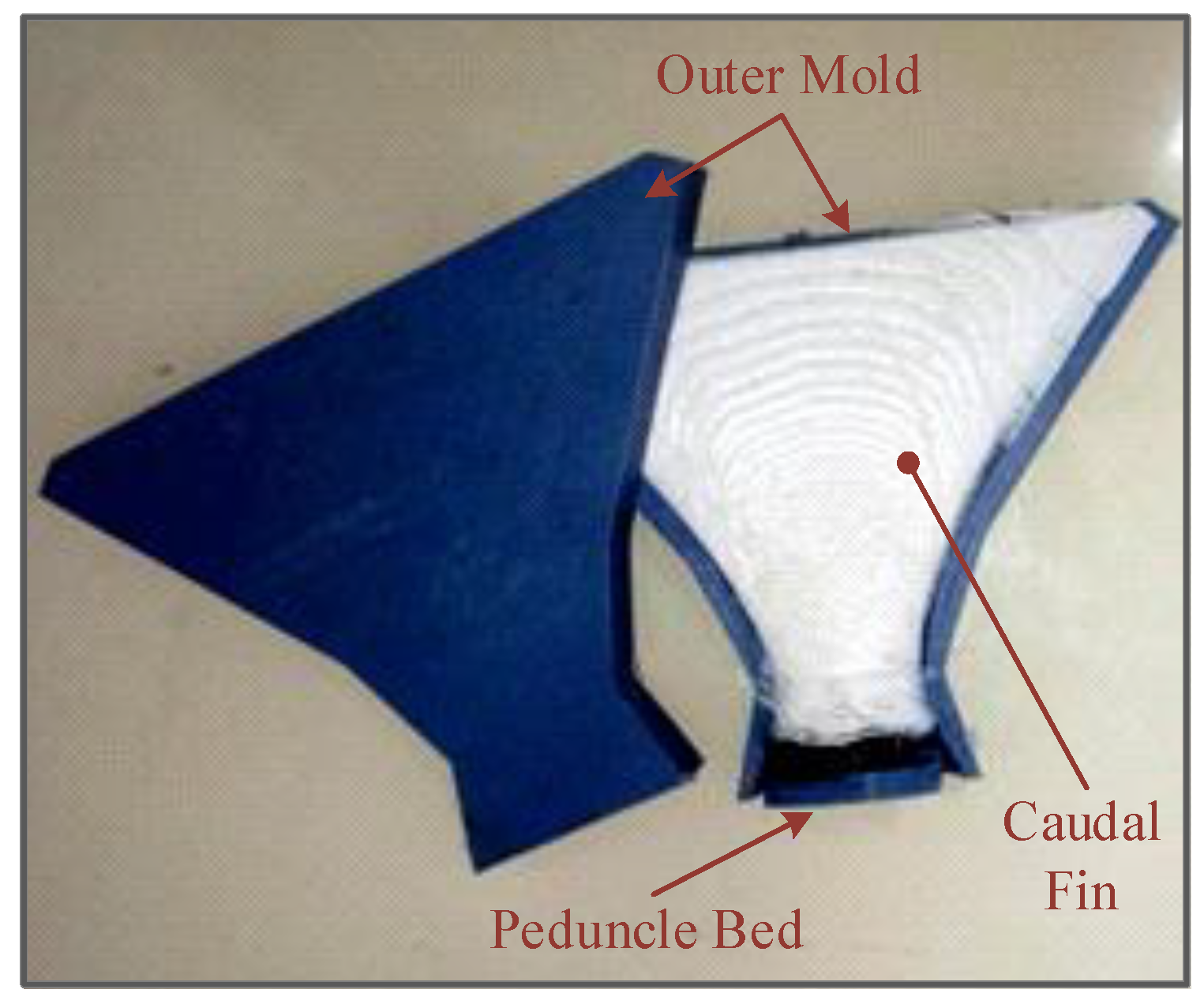
The outer caudal fin mold is also designed and produced with 3D-printing technology as shown in
Figure 7. RTV-2 white mold silicone is poured into the outer mold and the peduncle is placed in the silicon.
Finally, the mechanical structure necessary to obtain the following sinusoidal joint angles is achieved.
Here, A1 and A2 define the amplitude values of the first and second link angles; f indicates the flapping frequency of the tail mechanism; φ1 and φ2 describe the phase differences of the first and second link angles related to each other.
3.2. CoG Control Mechanism Design
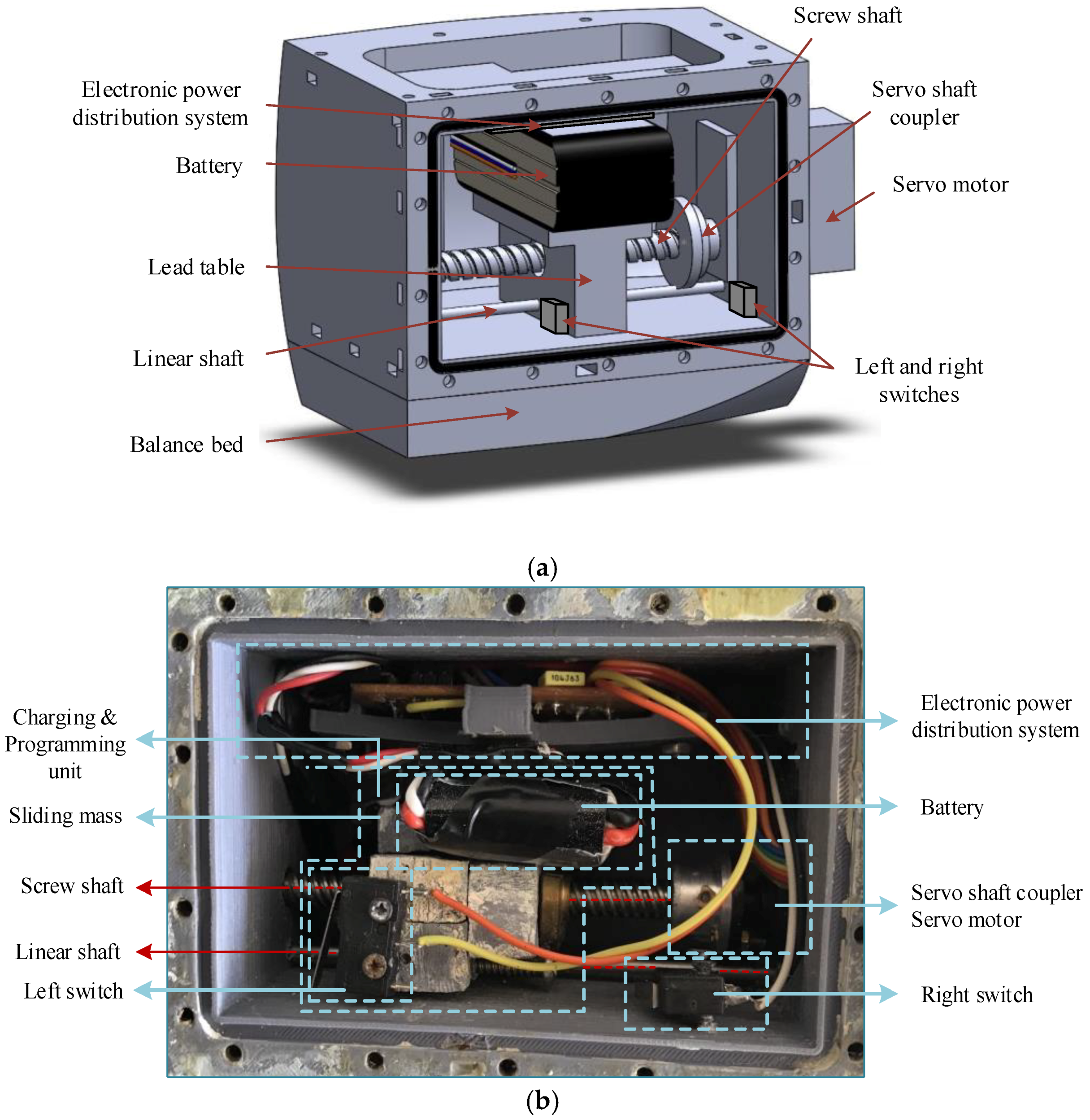
The mechanical structure of the CoG control mechanism designed for three-dimensional motion is given in
Figure 8. The diving force generated by the CoG control mechanism located in the main body enables the robotic fish to perform the up-down motions, which is one of the important swimming mode of the fish, by turning the robot in the y axis. The designed mechanism mainly consists of one sliding mass moving in the x axis with the mechanical components and one AR3603HB RC servo motor. The x axis is in the same direction as the nose of the robotic fish. The sliding mass, which allows the CoG change, occurs as a prismatic lead table and a battery fixed on the table. The masses of lead table and battery are approximately 300 gr and 90 gr, respectively. The RC servo motor is fixed between the CoG motor housing and main body. The T8 threaded spindle and nut system mounted on the servo motor gear shaft is used to ensure motion of the lead table. The rotation of the servomotor is converted into linear motion by the screw shaft. A constant linear shaft is used in the same direction as the threaded spindle to prevent roll effects that may occur at the moment of motion of the table. Two boundary switches are placed to the left and right sides to determine the boundaries of the linear motion of the table along the x axis. The left switch is fixed to the table and the right switch is fixed to the main body in the opposite direction. The electronic power distribution system, to which the battery is connected and from which the voltage levels are determined, is fixed to sliding mass.
The control unit and the first joint upper shaft are located above the main body. A cable channel is formed between the upper terminal and the main body for the transmission of electronic connections. In order to ensure the sealing between these two parts, the surfaces are covered with fluid seal. This channel is fitted with an O-ring with grease oil. The surfaces of the other body parts are also mounted by coating with fluid seal to increase the waterproofness.
The CoG position of the robot should be in the same direction as the lift center and slightly below. There is an added lead with mass of 120 gr in the balance mass located between the main body and first bottom link housing. With this structure, balance in the vertical direction is ensured and the roll angle of the robotic fish becomes nearly 0° while the robotic fish is swimming in water.
In addition, the density of the robotic fish prototype is designed as nearly 998 g/m
3, which is so close to the density of water. Thus, it is ensured that the robotic fish prototype can easily swim in three-dimensional space and the robot ascends to the water surface when the diving force is not applied. Equation (3) gives the necessary expression to determine the robotic fish volume
Δf and total mass
m according to the desired mass,
Finally, the torque generated by CoG control mechanism can be defined as,
In this equation, g is the acceleration of gravity; lx is the distance from the Center of Mass (CoM) of the prototype; hx is the height from the CoM. θ and ϕ represent the pitch and roll angles, respectively.
3.3. The Front Sight Unit Design
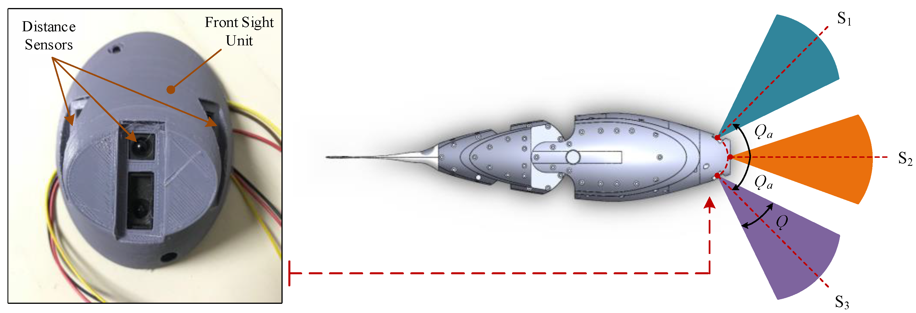
The front sight unit of the robotic fish prototype is designed with the sensors placed horizontally parallel to each other in the front axis so that the robotic fish can autonomously swim, avoiding obstacles in the water. As shown in
Figure 9, this unit is divided into three sight distances as left, right and front sections. A Sharp GP2Y0A21YK0F infrared distance sensor is used in each section.
The position of the front sensor is centered in the same direction as the x-axis and the left and right sensors are located with the front sensor at angular intervals of 45° (Ǫa). The linear measurement range for each sensor is 6–80 cm, with S1, S2 and S3, which are the distance sensors in the left, front and right, respectively. The measurement range of these sensors is set to 6–60 cm to determine the obstacles at acceptable intervals in the experimental studies. Here, Ǫ is the obstacle detection angle at the sight distance of a sensor and it is nearly 40° for the sensors of the robotic fish.
4. Electronic System Design of the Prototype
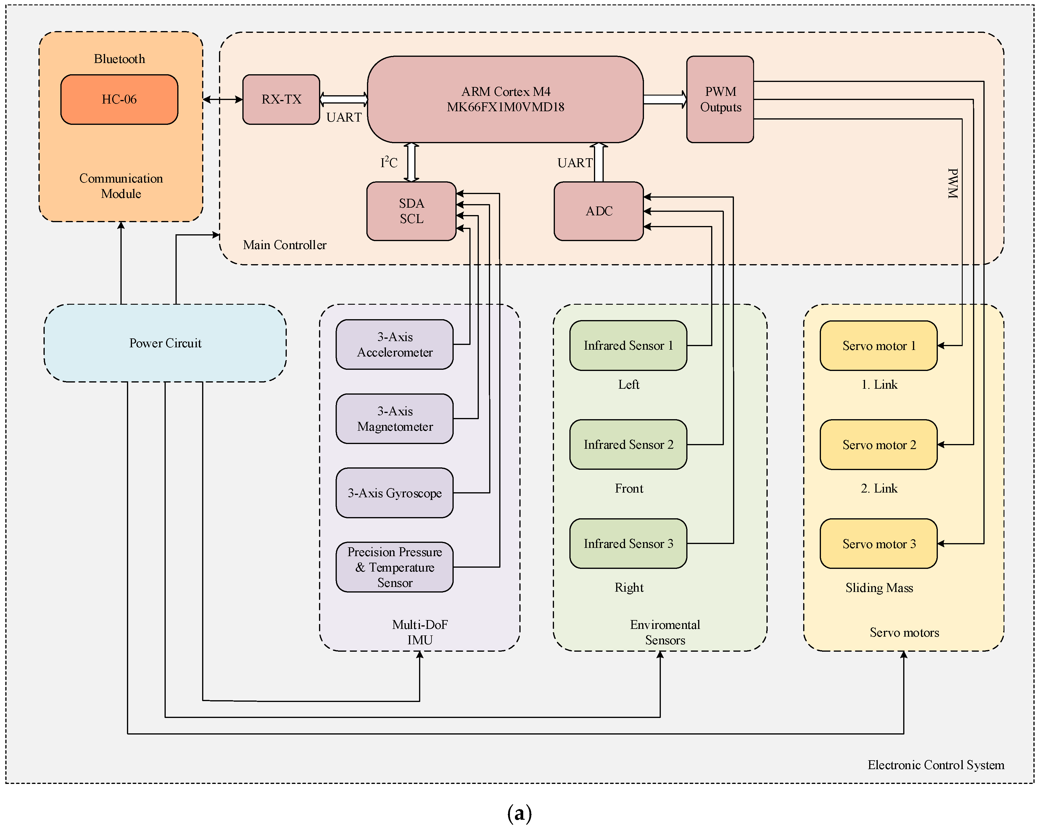
As shown in
Figure 10, electronic system of the robotic fish contains an integrated software and hardware that is capable of power, communication, perception and locomotion control functions. Electronic hardware system actuates the mechanic parts and collects the environmental data. According to the collected environmental data, the desired locomotion coordination of robotic fish is provided by the developed CPG control algorithm.
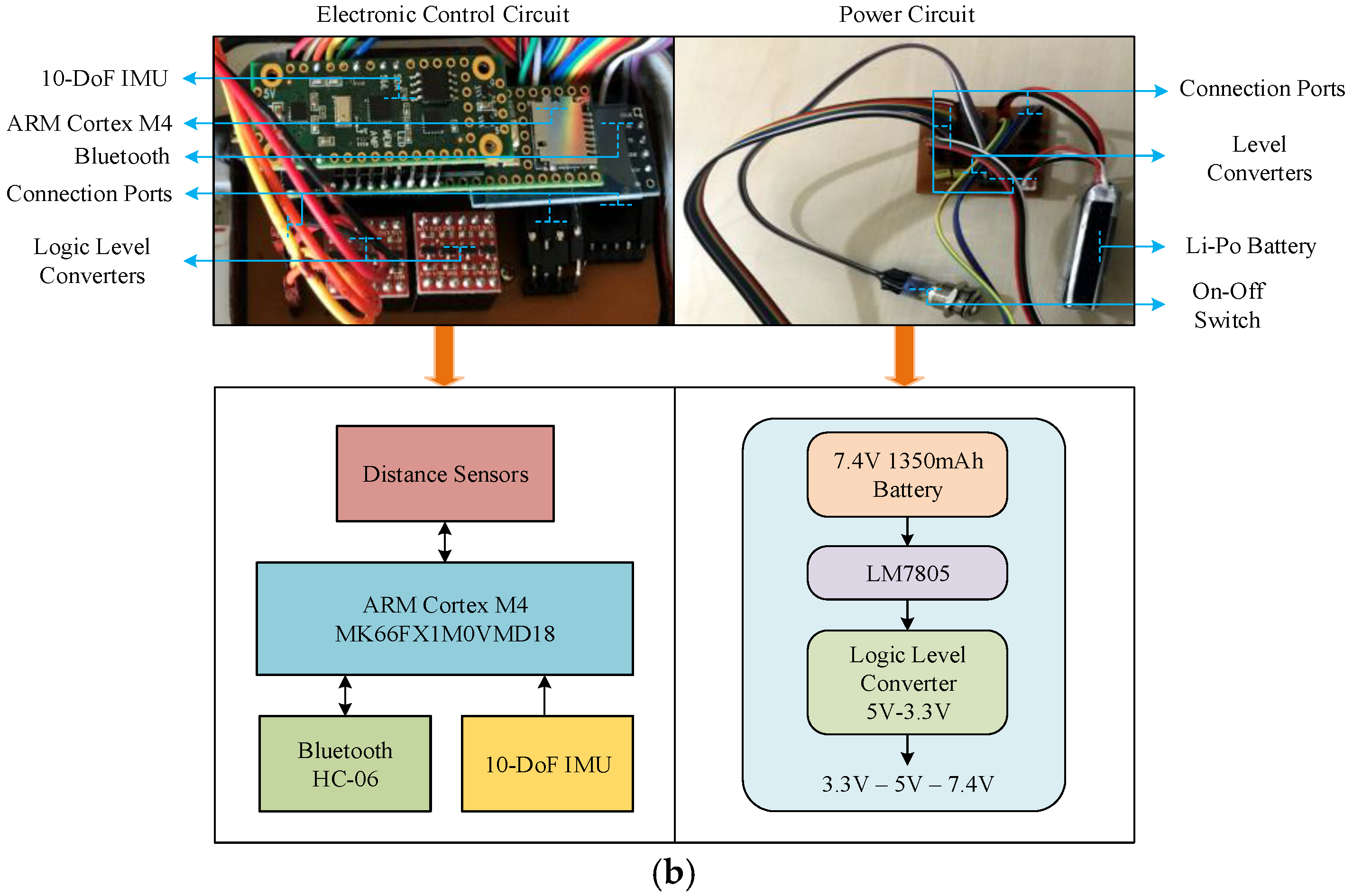
A 7.4 V 1350 mAh Li-Po chargeable battery is used for the power supply of the robotic fish. Li-Po battery is smaller, lighter, longer-lasting and it can store more energy than other rechargeable batteries. A power distribution circuit is designed to adjust the voltage values of other elements as the supply voltage levels of the electronic hardware components are different from each other. In the power distribution circuit, the 7.4 V voltage level of the battery is converted to the necessary 3.3 V and 5 V values by logic voltage level converters. In addition, 16 mm waterproof on-off switch, charge and programming connections are also transferred from the power distribution circuit. Also, programming and charging connection inputs are located in the main body. The communication between the Bluetooth module and microcontroller is realized by the RX/TX serial communication protocol. In order to detect obstacles on the left, right and front of the robot, three Sharp GP2Y0A21YK0F infrared distance sensors are connected to ADC inputs of the microcontroller. The mechanical motions of the prototype are provided by servo motors and servo motors are driven by PWM signals.
The modularly designed electronic control system is an integrated circuit board that includes a microcontroller board, Prop Shield 10-DoF IMU motion sensor module, Bluetooth module and logic voltage level converters. This circuit is located in the same direction of the x axis of the robot. IMU module is used with the 100 Hz sampling frequency to determine roll, pitch and yaw angles of the robot and to measure linear position and speed information in three-dimensional space. At the same time, environmental temperature can be measured. IMU has one FX0S8700CQ 6-axis linear accelerometer and compass sensor, one FXAS21002C 3-axis gyroscope and one MPL3115A2 atmospheric pressure and temperature sensor. The information from the IMU module is transferred to the microcontroller with I2C, which is a synchronous serial communication protocol, by (Serial Data) SDA and (Serial Clock) SCL. The microcontroller performs the rhythmic motions of the prototype with the intelligent control algorithm by evaluating the data received from the sensors and it also provides the simultaneous continuity of these motions. There is a 32 bit 180 MHz ARM Cortex M4 MK66FX1M0VMD18 microprocessor on the control circuit. It has 1 Mb flash memory, 256 Kb RAM and 4 Kb EEPROM as an internal memory.
The developed robotic fish prototype can swim both autonomously and handle the wireless information sent by the user computer. In addition, near the water surface, the data of the sensors can be transferred simultaneously to the user computer by Bluetooth communication.
5. Locomotion Control
In order to analyze the characteristic performance of the robotic fish prototype, CPG-based locomotion controller is designed. In this section, the general structure of the CPG controller inspired by the Lamprey spinal cord in [
37,
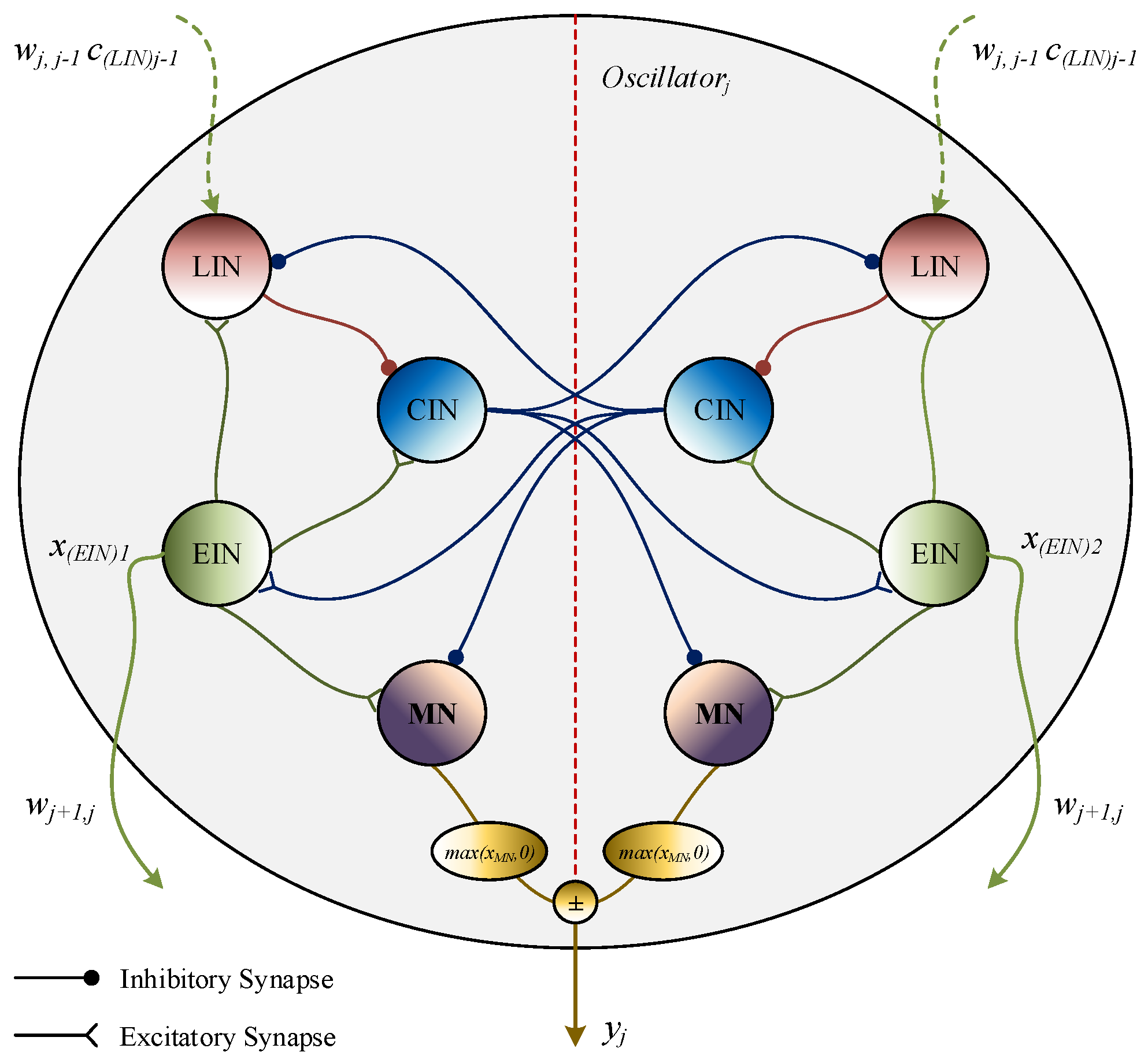
38] is given. Neural Lamprey CPG model produces rhythmic oscillatory outputs and also amplitude, period, phase difference and offset of the outputs can be easily changed by adjusting the model parameters. The proposed model consists of one Motor Control Unit (MCU) and two oscillators which generate motion of the tail links. As shown in
Figure 11, a neural oscillator is divided into two symmetric parts and each part contains four different interneurons, namely Crossed Interneuron (CIN), Lateral Interneuron (LIN), Excitatory Interneuron (EIN) and Motor Neuron (MN).
An oscillator model is defined as the following equations;
In this equations; i, j and k represent the left and right parts, oscillator number and neuron number in the each oscillator, respectively. xi is the membrane potential; yj is the oscillator output; parameters τ, β and A are output of the period, offset and amplitude, respectively. wik and wij are the interneuron and oscillator synapses. si defines the membrane potential of the presynaptic neurons and cj with wij define the neurotransmitter potential to the postsynaptic neuron. Also, the top line of the subscript indicates the opposite side in the same oscillator.
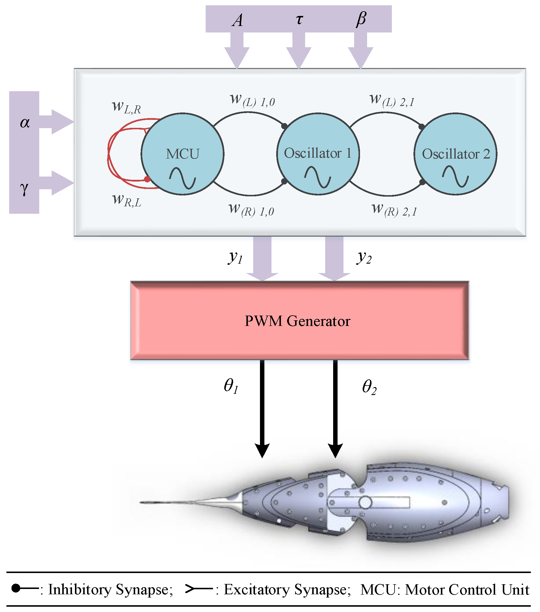
MCU is designed in the same structure. However, there are two different synapses (wL,R, wR,L) from EIN to LIN. wL,R = α/(α + γ) and wR,L = (−γ)/(α + γ) determine the phase difference of the links. In the oscillator model, a unidirectional inhibitory chained CPG network is constructed to generate the rhythmic oscillatory outputs. The design of the CPG model used in this study is not further elaborated here, as it is the content of another article prepared by the project team.
In order to analyze the characteristic performance of the robotic fish prototype, the link angles of the robotic fish are generated for different input parameters using the CPG model given with the block diagram in
Figure 12. The input variables are the amplitude of the robotic fish link angles, the period
τ, the offset
β and the phase difference coefficients (
α,
γ). The oscillator outputs
y1 and
y2 define the first and second joint angles, respectively. The unidirectional left and right synaptic weights between all oscillators are selected as −1. In order to determine the phase difference φ
12 between the two links at the desired intervals,
γ is fixed at 0.2 in the experimental studies and
α is changed in the interval of (0,1].
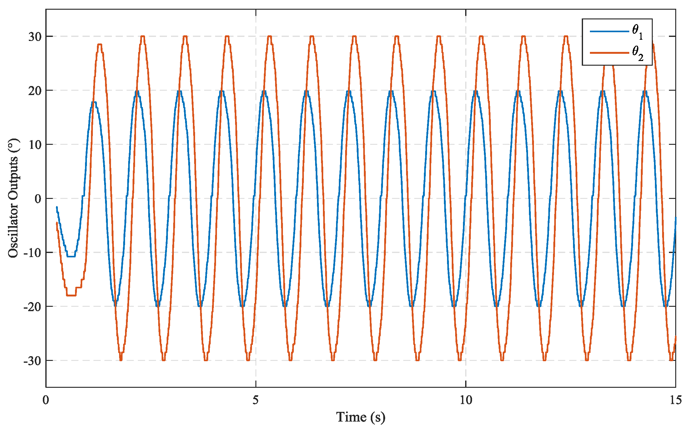
An example of the CPG outputs generated with ARM Cortex M4 microcontroller is given in
Figure 13.
It can be seen from
Figure 13, rhythmic oscillatory outputs are smoothly obtained by the proposed CPG network. When the CPG output and a simple sinusoidal function are compared according to variations of amplitude, frequency and offset, the sinusoidal function has distortion and transitions are quite sharp. So it may cause mechanical faults, strains and unexpected swimming patterns. However, CPG oscillator output is quite smooth. Thus, arbitrary flapping frequency, oscillation amplitude and offset can be obtained through modulating corresponding CPG parameters and rhythmic, smooth and expected transitions occur depending on these modulations.
6. Experimental Results and Discussion
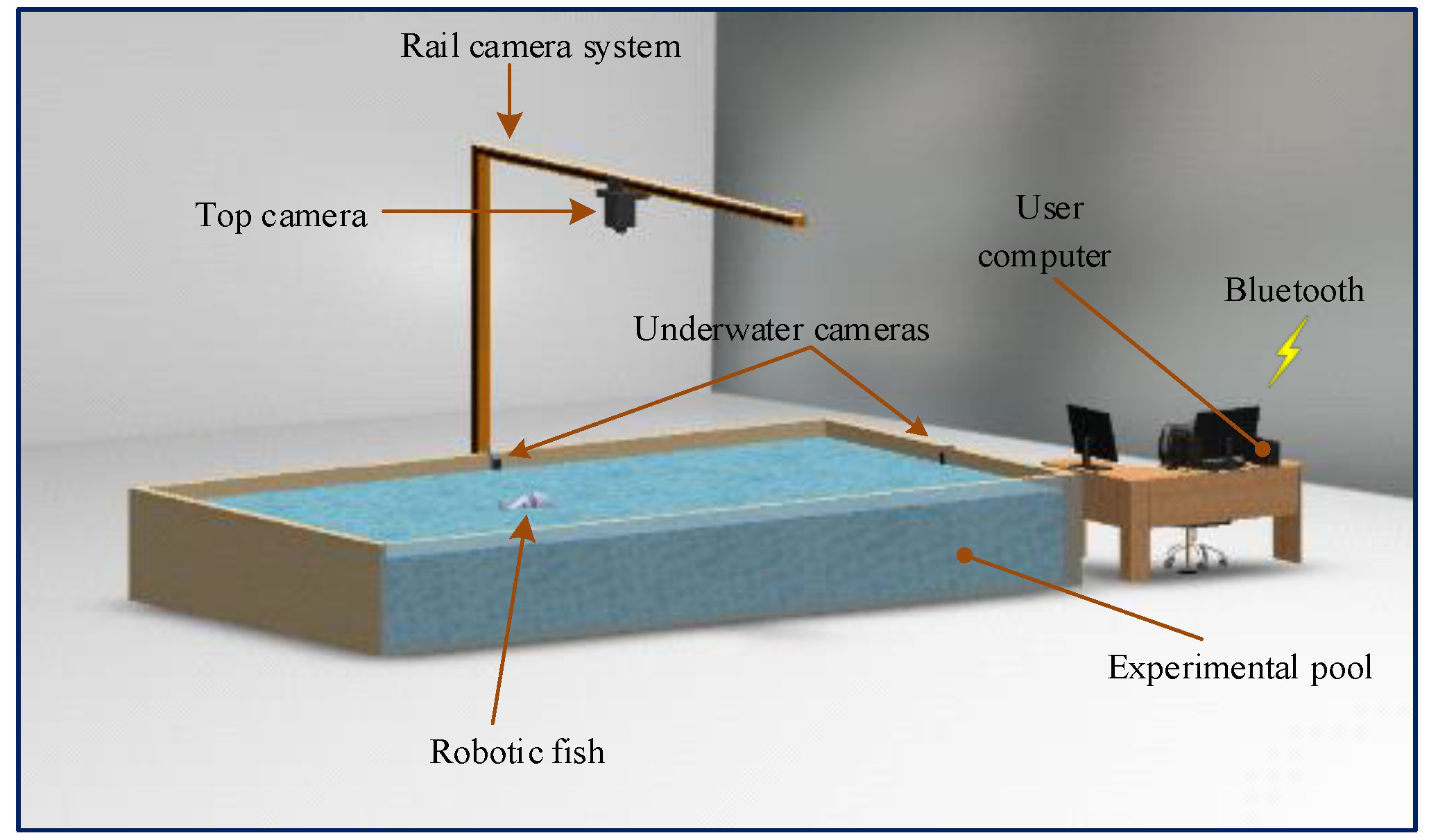
An experimental system is realized to evaluate the robotic fish prototype in a real environment. In this system; 200 cm wide, 300 cm long and 66 cm depth experimental swimming pool, one Sony FDR-AX53 4K top camera, two GoPro Hero5 Black Edition underwater action cameras, and one user computer with i7 2.4 GHz processor, 8 GB DDR4 RAM and 2 GB graphics card are located as shown in
Figure 14.
In order to extract the characteristics of the robotic fish prototype, speed variations corresponding to flapping frequency changes and turning radius, and linear and angular speed changes according to offset (β) applied to links are analyzed in the experimental system. In this experimental system, 72 different experimental studies have been carried out to obtain the characteristics of the robotic fish during 30 days.
Forward speed changes of the robot are obtained according to flapping frequency variations. In this analysis, there are 60 experiments with three different amplitude values as {(
A1 = 10,
A2 = 20); (
A1 = 20,
A2 = 20); (
A1 = 20,
A2 = 30)}. The forward speed values according to the parameter changes belonging to this analysis are presented in
Table 2. The CPG parameters are chosen as β = 0, α = 0.8 and φ
12 = 45°. As can be seen from
Table 2, the forward speed of the robot increases approximately linearly with the increase of flapping frequency. At larger amplitude values, the forward speed also increases due to larger thrust force generated by the tail mechanism. The amplitude is determined in the range of [10–30]° as a mechanical turning angle of each link of the robotic fish prototype limited to maximum ± 45°. The maximum forward speed value is obtained as 0.4224 m/s at the 2 Hz flapping frequency. In addition, speed variation due to Body Length (BL), which is another speed performance criterion in underwater robots, is investigated. The maximum forward speed for the robotic fish prototype is calculated as 0.8448 BL/s. The forward speed change analysis performed above for different amplitude values are also reexamined for different phase values. Experimental analyses are performed for three phase differences as {φ
12 = 60°, 75°, 90°}. In
Table 3, forward speeds are presented. The CPG parameters are chosen as
A1 = 20,
A2 = 20, β = 0 and α = 0.5. It can be seen in this analysis that the phase difference between the angles of the links increases, the forward speed value decreases for that as the thrust force produced by the tail mechanism decreases. The maximum forward speed is obtained as 0.4258 m/s for a 60° phase difference at 2 Hz flapping frequency. The speed value according to BL is also calculated as 0.8516 BL/s.
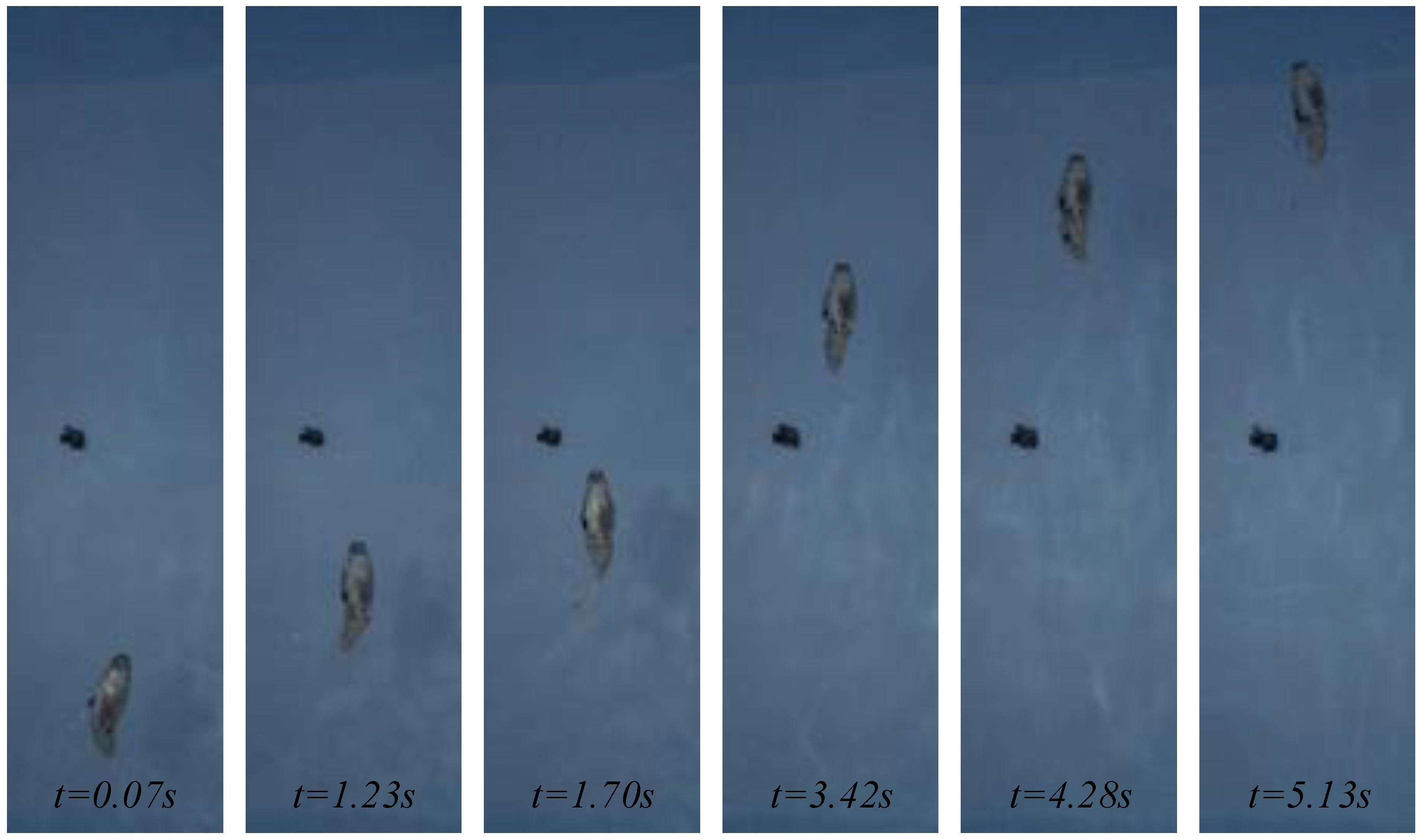
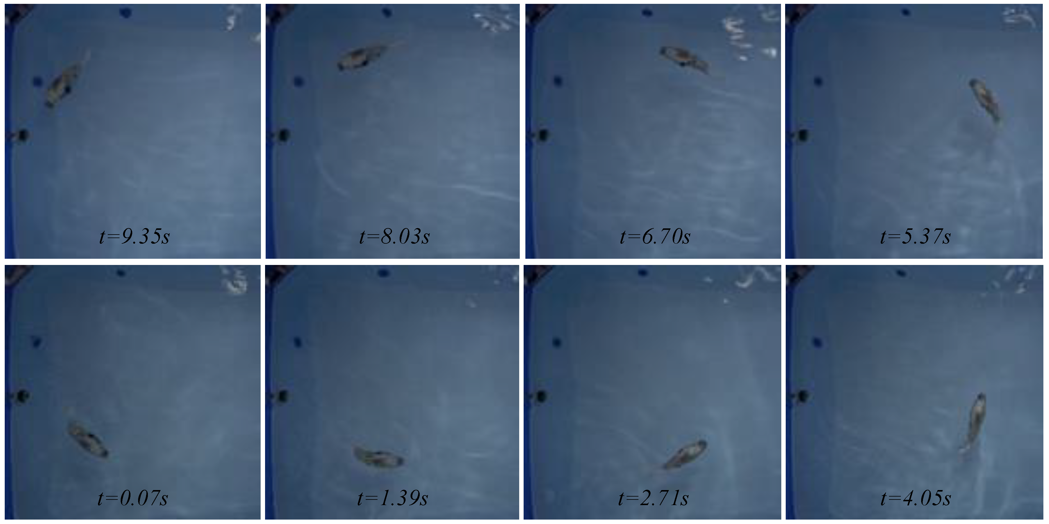
Figure 15 shows the experimental forward swimming motion for parameter values of
f = 2 Hz,
A1 = 20,
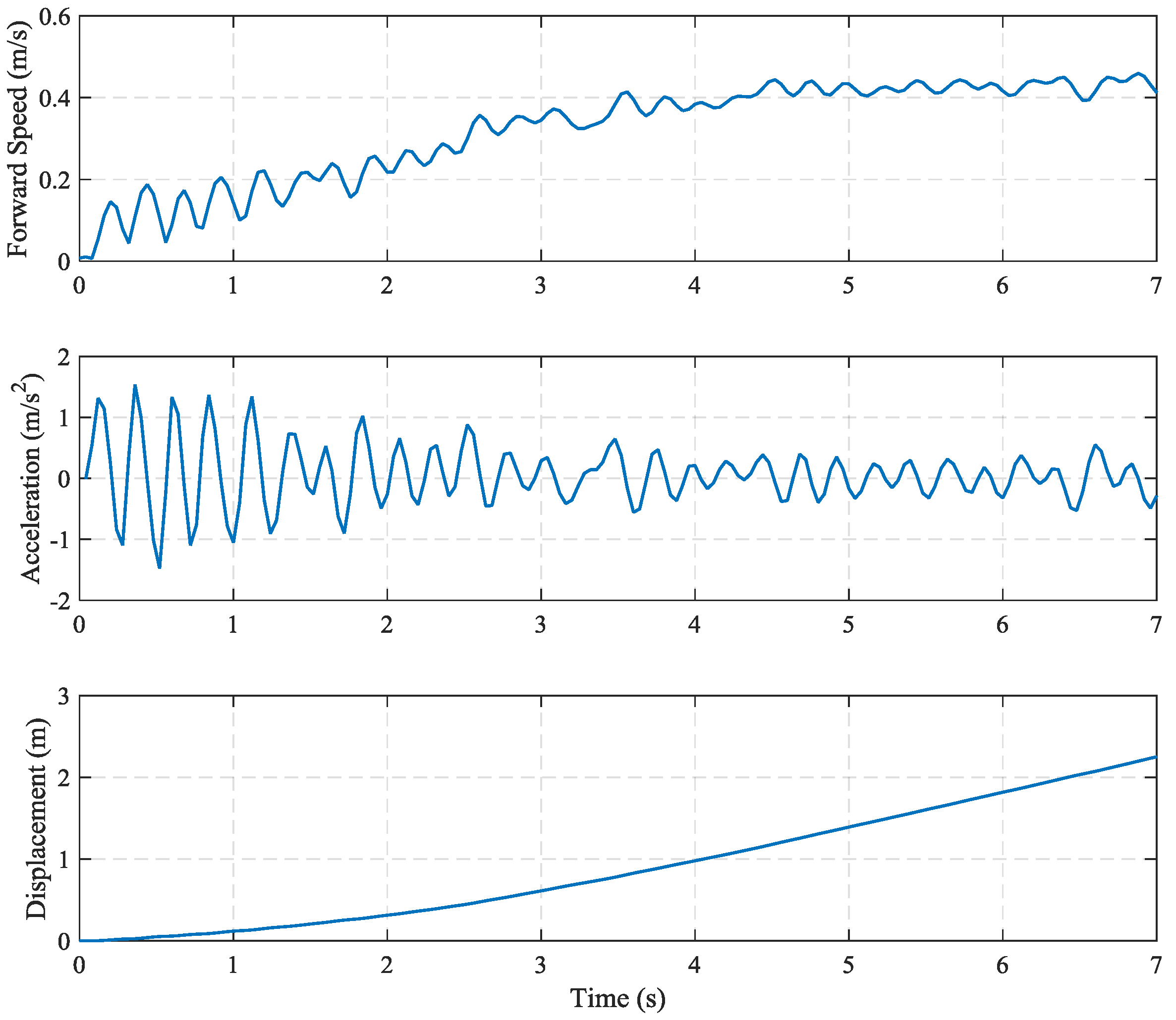
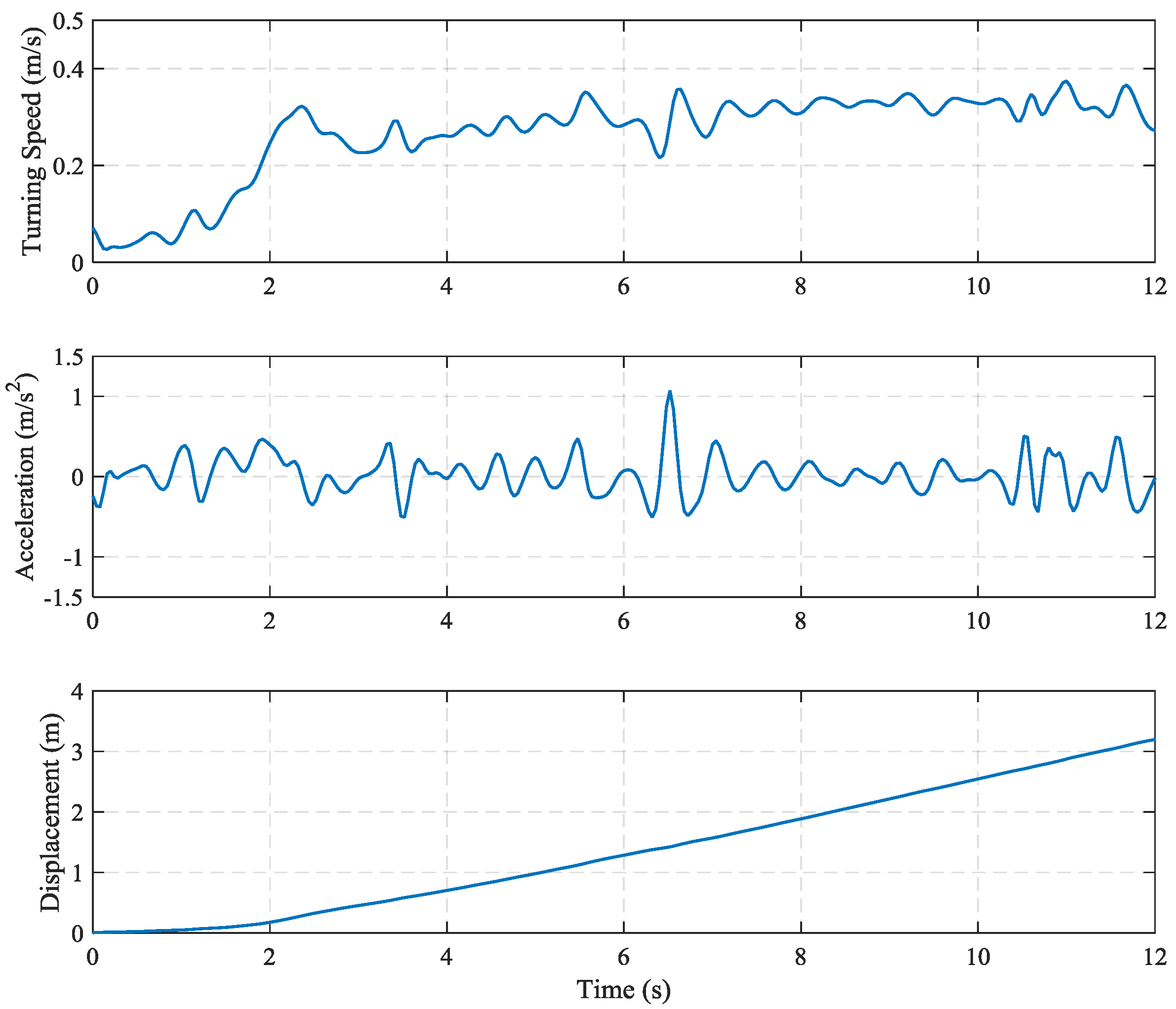
A2 = 20, β = 0 and α = 0.5 where the maximum forward speed value of the robotic fish prototype is obtained. Forward speed, acceleration and displacement of the robotic fish are also given in
Figure 16.
As shown in
Figure 16, the forward speed of the robotic fish reaches to the steady-state value in about 4.3 s and when the acceleration is examined, it is oscillated with small amplitudes around zero at approximately the same time as speed. Due to the speed remaining constant within a certain limit, the acceleration is also keeps constant around zero. Thus, the robotic fish cruises 2.3 m distance at the end of 7 s.
Turning motion of the robotic fish is analyzed with different turning radius and speed against offset β changes. In this part of the study, turning ability of the robotic fish is performed according to different parameter values in the experimental system. The turning radius and linear and angular speeds against the offset changes of the links are investigated at different frequency values of the prototype. The CPG parameters are chosen as
A1 = 10,
A2 = 20, α = 0.8 and φ
12 = 45°. The values of the turning radius and linear and angular speeds obtained from the experimental studies are presented in
Table 4. In this analysis, it can be seen that the turning radius decreases with the increase of the offset for the constant frequency. Experimental studies are performed for four different frequencies as
f = [0.5, 1, 1.5, 2] Hz. It is observed that the turning radius with the low frequency is larger than the larger frequency at the fixed offset. Also, linear and angular speed performances of the robot are obtained.
As shown in
Table 4, the linear turning speed obtained from the turning motion shows very small decreasing changes for the constant frequency. This means that the linear turning speed remains almost constant despite of the offset change for constant amplitude and frequency values. Contrary to the linear turning speed, it is seen that the angular turning speed increases with the offset increase for constant amplitude and frequency values. Increase of the offset value leads to the increase of the turning angle of the robot with the horizontal x axis. Thus, it causes both the decrease of the turning radius and the increase of the angular turning speed. At the same time, the linear and angular speed values also increase with the increase of the flapping frequency for constant offset values. The minimum turning radius, the maximum linear speed and the maximum angular speed of the robotic fish are obtained as 0.4387 m at 1 Hz, 0.3266 m/s at 2 Hz, and 0.62 rad/s at 2 Hz, respectively. Also, maximum linear turning speed is calculated as 0.6532 GU/s according to BL.
In these experiments, three different performance criterions of the robotic fish evaluated above according to the same parameter changes of CPG are presented.
Figure 17 shows the experimental images taken from the top camera for the turning motions with the parameter values of
f = 2 Hz,
A1 = 10,
A2 = 20,
β = 0.8 and
α = 0.8. The time-dependent variations of the linear turning speed, acceleration and displacement are given in
Figure 18, respectively.
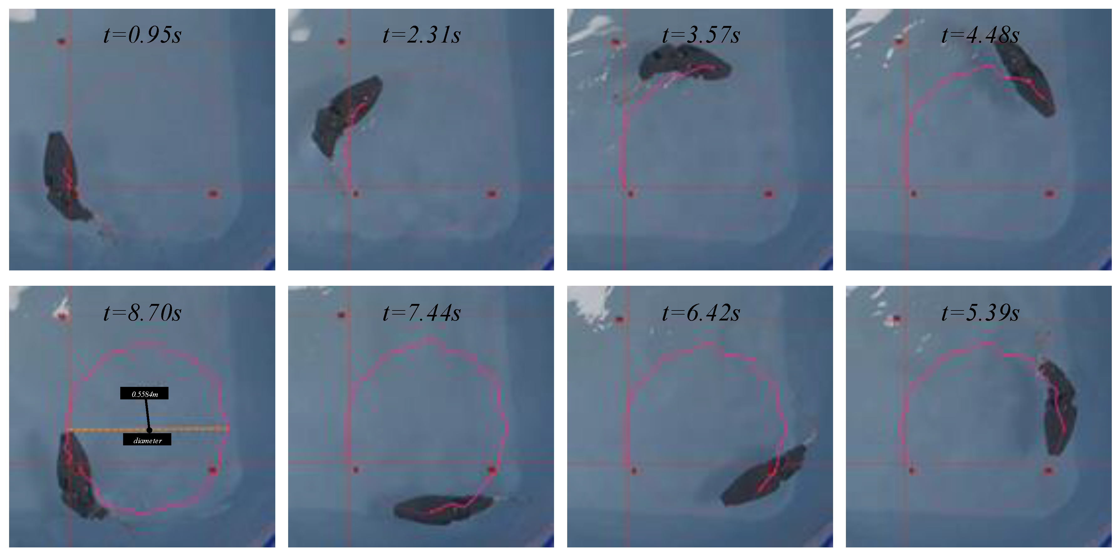
The turning experiment is repeated with parameter values of
f = 1.5 Hz,
A1 = 20,
A2 = 20,
β = 0.85 and
α = 0.8 to ensure smaller turning radius than with those parameter values given in
Table 4. The images of this experiment are presented in
Figure 19. The parameter values used in this experiment are also chosen as close to the mechanical limits of the robotic fish. In this experiment, the robot realizes a circular turning motion with radius of 0.2792 m, linear turning speed of 0.2343 m/s and angular turning speed of 0.7136 rad/s, respectively.
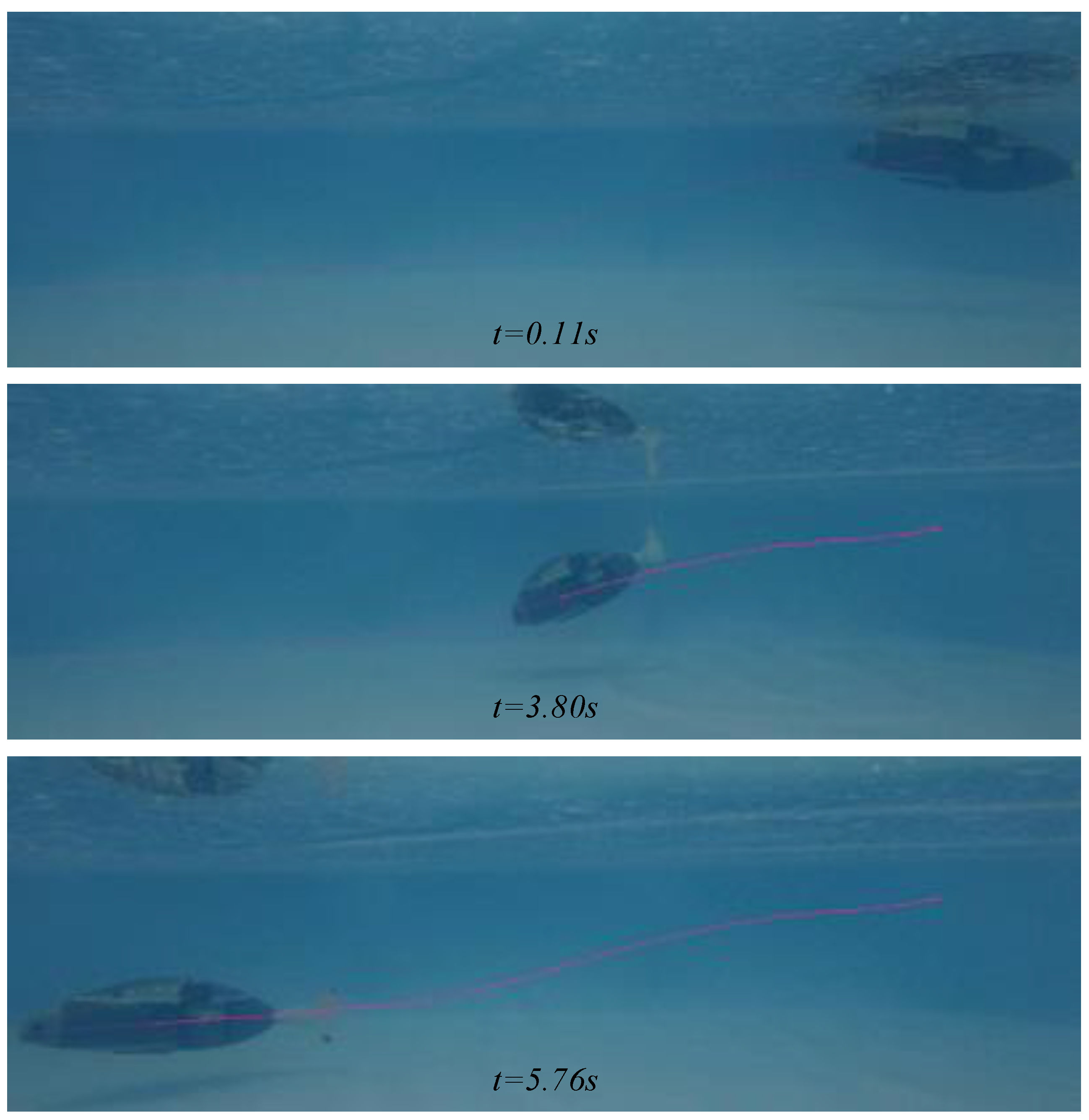
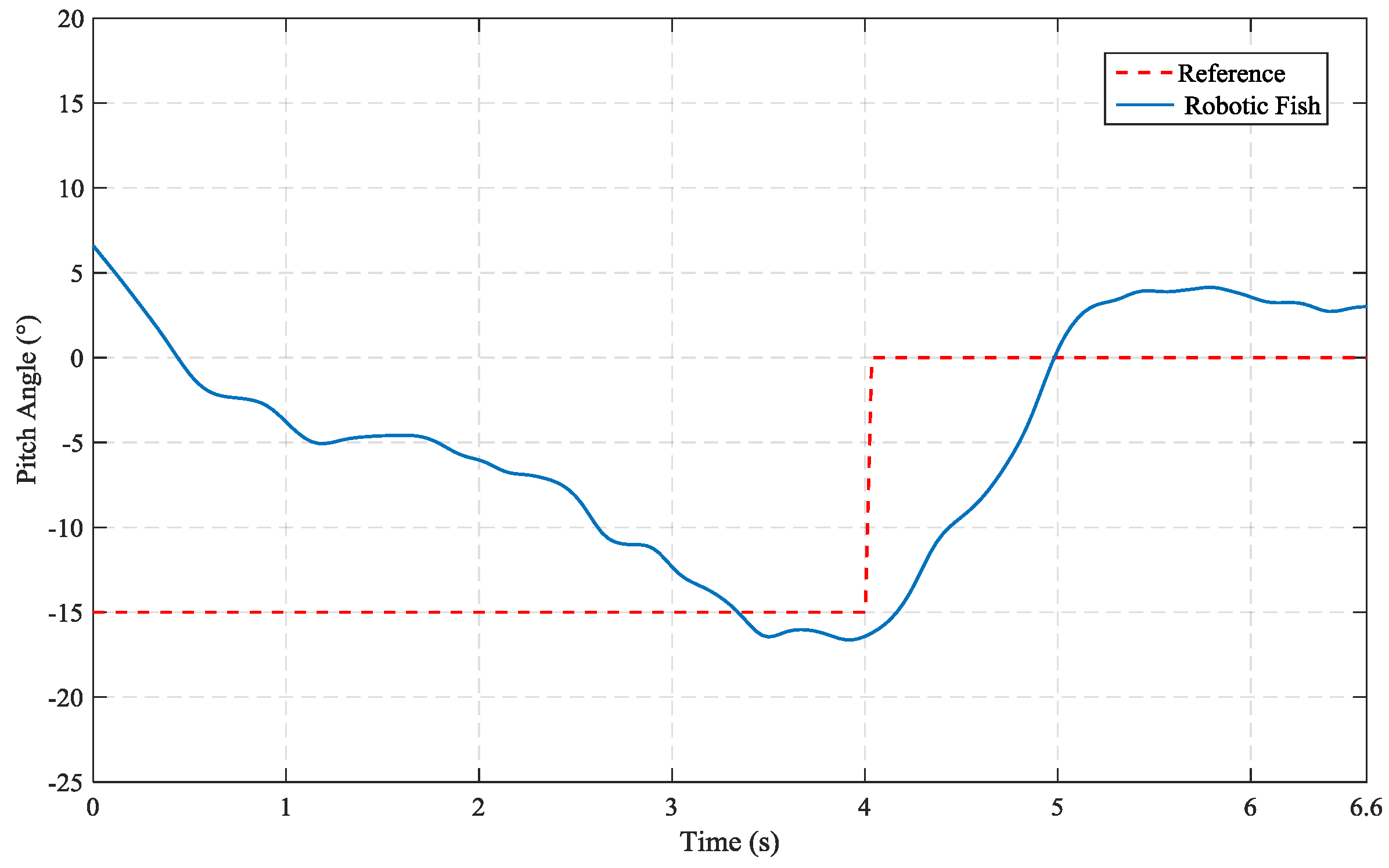
At the same time, the diving motion response is given in
Figure 20. When robotic fish reaches the steady-state, link angles become stable and generate small amplitudes. For this experiment, firstly, the reference pitch angle is kept at −15° for 4 s and then at the end of the 4 s period, this angle is intended to be at 0° to remain its level. The snapshots obtained from the underwater action camera are located in the middle of the long edge of the pool. The pitch angle of the robot according to the reference pitch angle is also shown in
Figure 21.
In this analysis, the sliding mass is moved forward and backward in the CoG control mechanism to keep the pitch angle at the desired level with a conventional proportional control structure as below,
It is seen from
Figure 21 that the developed CoG control mechanism is sufficiently effective to keep the prototype at the desired pitch angle.
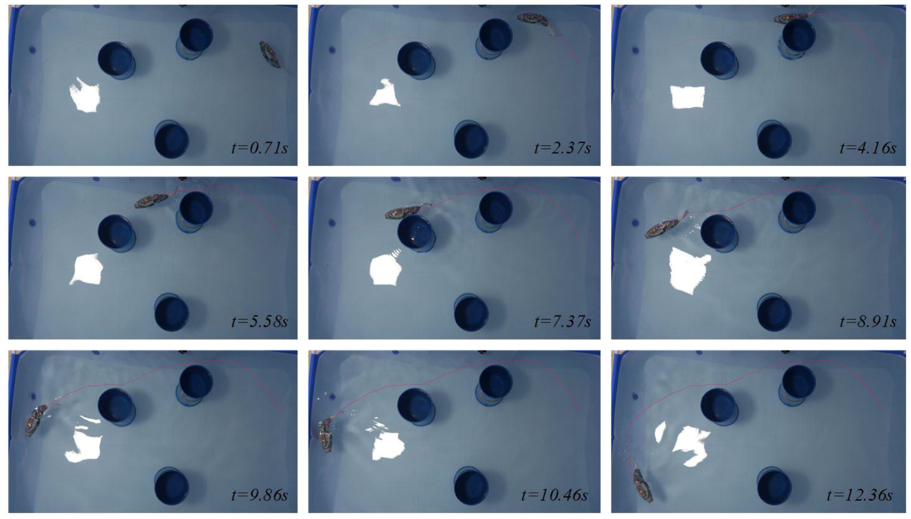
In addition, a natural scenario is created in the presence of randomly placed obstacles in the pool in order to ensure autonomous swimming performance of the prototype. In this scenario, the robotic fish starts to swim randomly from any side of the pool. During the forward swimming motion, the front, right and left distance sensors detect the pool edges and randomly place the obstacles. Thus, autonomous swimming is performed; snapshots of this experiment are given in
Figure 22.
An autonomous swimming experiment of the prototype was performed with randomly placed obstacle sequences. When the results of this experiment were evaluated, it was observed that obstacle avoidance performance is effective and it seems promising for future real-world exploration and survey missions.
7. Conclusions
This study presents the biomimetic design and manufacturing of the intelligent robotic fish prototype (i-RoF) based on bio-inspired swimming to perform real-world exploration and survey missions. The developed robotic fish mimics Carangiform BCF-type swimming modes with two-link tail mechanism. Also, a CoG control mechanism is developed to perform three-dimensional swimming. The CPG-based locomotion controller is adapted to generate robust, smooth and rhythmic oscillatory swimming patterns. The proposed CPG model is designed as a Lamprey spinal cord to ensure intelligent control. The robotic fish prototype for three-dimensional motion abilities is investigated in the real experimental system. In these analyses, more than 72 different experimental studies were performed to obtain the characteristics of the prototype.
The developed robotic fish consists of five basic components including main body, the control unit, the front sight unit, two-link propulsive tail mechanism and flexible caudal fin. The dimensions of tail links and flexible caudal fin are determined by analyzing 50 swimming patterns for forward and turning motions of the real carp fish. The obtained link lengths are adapted to designed model. Robotic fish swimming patterns are also analyzed in SimMechanics environment for forward and turning motions. It can be seen from these analyses that determining prototype dimensions according to real fish is quite convenient. Each solid part of the prototype is produced by using PLA in 3D-printing technology. The flexible caudal fin of the robotic fish prototype is also produced by using white color mold silicone. All parts are covered with epoxy resin to prevent possible leakage from the micro pores formed in the parts produced with 3D-printing technology. Finally, the outer surface is painted with synthetic paint to prevent leaks that may be caused by capillary cracks during assembly. In order to test the sealing performance of the mounted parts, they run during 6 hours in a water-filled test pool. The success of sealing tests is observed.
Three-dimensional motion analyses are performed in the real experimental system to validate the proposed design. For these validations, speed variations corresponding to flapping frequency changes and turning radius and linear and angular speed changes according to changes in offset (β) applied to links are analyzed in the experimental system. For the maximum forward speed of the robotic fish, parameter values are determined as f = 2 Hz, A1 = 20, A2 = 20, β = 0, α = 0.5 and γ = 0.2, respectively. In this analysis, the robotic fish prototype cruises nearly 2.3 m distance at the end of 7 s. Turning experiments are also examined for various parameters of the robot. In order to ensure the minimum turning radius of the prototype, the parameter values are chosen as f = 1.5 Hz, A1 = 20, A2 = 20, β = 0.85, α = 0.8 and γ = 0.2, respectively. In this analysis, the robotic fish realizes a circular turning motion with a radius of 0.2792 m, a linear turning speed of 0.2343 m/s and an angular turning speed of 0.7136 rad/s. For the examination of the diving motion, two reference pitch angles are performed and sufficiently effective depth performance is acquired. In addition, an autonomous swimming experiment is performed with randomly placed obstacles in the pool. According to the experimental studies, the swimming performances of the developed prototype are quite effective for missions of real-world exploration and survey with its novel fish-like design.
In the future work, the closed loop control performances of the prototype will be examined with different control structures. As well, swimming performance of the robot will be tested in different watercourses.

 ,
, 


