1. Introduction
In the last decade, terahertz (THz) technology, which has great potential in sensing, imaging, and spectroscopy, has attracted attention [
1,
2]. Among the emerging THz devices, THz absorbers play an important role in several THz systems, including sensors, stealth materials, and detectors [
3,
4,
5].
Since Landy et al. presented the concept of a metamaterial absorber (MA) in 2008 [
6], MA has attracted great interest due to its enormous advantages such as low cost, small size, and ultrathin thickness. Various MAs, such as wideband absorbers [
7,
8,
9] and multiband absorbers [
10,
11,
12], have been widely investigated in recent years. In many applications, the polarization-dependent absorption is useful and demanded. The polarization information can further increase the depth accuracy of detected images [
13] and is of great significance in remote sensing, biomedical imaging, and image sensors. Sakurai et al. proposed an L-shaped polarization-dependent MA in the infrared region [
14]. Wang et al. presented a polarization tunable terahertz MA based on an asymmetric metallic resonant patch [
15]. Kim et al. realized a dual-absorption polarization sensitive metamaterial structure by composing four cut-wire bars [
16].
However, to the best of the authors’ knowledge, for a given polarization angle, most of the existing polarization-dependent absorbers show characteristics of perfect absorption only at certain frequency. Although absorbers can be effectively tuned to different working frequencies by reconstructing the geometries, it is very difficult to change the physical structure after fabrication. In addition, for some sensing and detecting applications, a tunable absorber, whose operation frequency can be tuned within a certain frequency range, is essential and necessary. Ho et al. introduced electrothermally actuated microactuators integrated with an Omega-ring metamaterial unit cell to provide continuous tuning [
17], but the fabrication of this structure was complicated. In our previous work, a polarization-dependent tunable terahertz MA based on a graphene monolayer was presented [
18]. Nevertheless, acquiring a perfect monolayer graphene sheet is still a challenge.
It has been verified that the absorption frequency of an MA based on liquid crystal (LC) can be dynamically tuned in the terahertz region due to the voltage-dependent birefringence of LC [
19,
20]. Based on this concept, a polarization-dependent LC tunable MA at terahertz frequencies based on a new metamaterial unit cell is proposed in this paper. The influence of the orientation on LC cells on the absorber’s absorption spectrum in two orthogonal directions is theoretically investigated. It is shown that a distinct absorption peak with no bias voltage is located at 239.5 GHz for TE-polarization and 306.6 GHz for TM-polarization. Moreover, it is experimentally demonstrated that, by controlling the bias voltage of LC molecules, the absorption peak can be tuned with a maximal frequency tunability of 4.7% and 4.1% for TE- and TM-polarization, respectively.
2. Structure Design and Principle of Operation
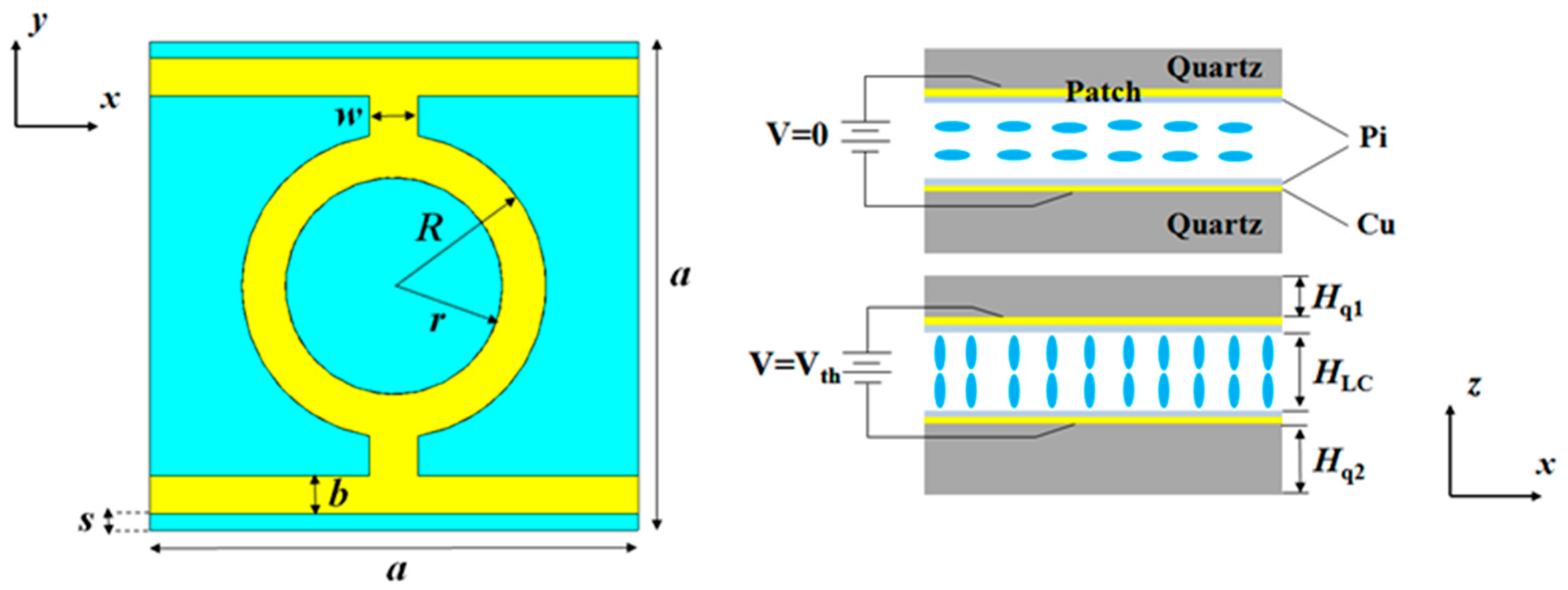
The structure of the unit cell of the proposed polarization-dependent tunable absorber is presented in
Figure 1. This unit cell is composed of a pair of metal layers printed on the surface of parallel quartz plates with a void between them, which is fully filled with a nematic liquid crystal. The metallic patterned layer at the upper surface of the quartz plate serves not only as a resonant structure, which shows characteristics of polarization dependence, but also as a top electrode of the whole tunable absorber.
It is well known that LC materials are composed of anisotropic molecules and that the orientation of LC molecules can be controlled with an external electrical field. Thus, by changing the bias voltage between two metal layers, the direction of LC molecules along the electric field vector of the incident wave, i.e., the permittivity of the LC layer, can be dynamically adjusted. To control the direction of LC molecules without applying a bias voltage, a thin layer of polyimide (Pi) is spanned on the inner surface of both metal layers. In the unbiased state (ε⊥), due to the static action of the polymer alignment layer, the long axis of molecules is parallel to the quartz surface. The bias voltage, which is applied across the biasing layers, rotates the LC molecules, which provides the maximal permittivity (ε||) at the saturation state, while the direction of the LC molecules is perpendicular to the cell walls. Therefore, the LC permittivity can be electronically varied between these two states, i.e., Δεeff = ε|| − ε⊥, thus the absorption frequency of the absorber can be shifted.
The geometrical dimensions of the unit-cell structure presented in
Figure 1 are as follows: a = 460 μm, b = 35 μm, R = 135 μm, r = 100 μm, w = 45 μm, s = 15 μm, H
q1 = 350 μm, H
q2 = 1000 μm, and H
LC = 45 μm. Both metal layers are made of a 0.5-μm-thick copper layer with a conductivity of σ = 5.8 × 10
7 S/m, and quartz plates are considered as a dielectric material with a relative permittivity of 3.78 and a dielectric loss tangent of 0.02. The absorptivity of an absorber can be determined by
, where A, S
11, and S
21 denote the absorptivity, reflection coefficient, and transmission coefficient, respectively. Since the transmission is equal to zero due to the existence of the copper ground plate, the absorptivity can be simplified as
.
3. Simulated Results and Absorption Mechanisms
The simulations were conducted by using the finite-element frequency-domain method, and the unit-cell boundary conditions were utilized in both the
x and
y directions. Meanwhile, the Floquet port condition was employed in the
z-direction. According to our previously reported results [
21], the LC material was assumed to be S200 in the simulations, where its permittivity in the unbiased state (ε
⊥) and the fully biased state (ε
||) was set to 2.47 and 3.06, respectively. In the simulation, the loss tangent of the LC layer is set to 0.02. Moreover, in this study, the LC is treated as a homogeneous material, which is widely used in the modeling of LC-based devices [
22,
23,
24], and the effective index of the aligned nematic LC is given by [
25]
where n
o and n
e represent the ordinary and extraordinary indices, respectively, and θ is the LC director angle. Since the LC is a nonmagnetic material, (1) can be rewritten by
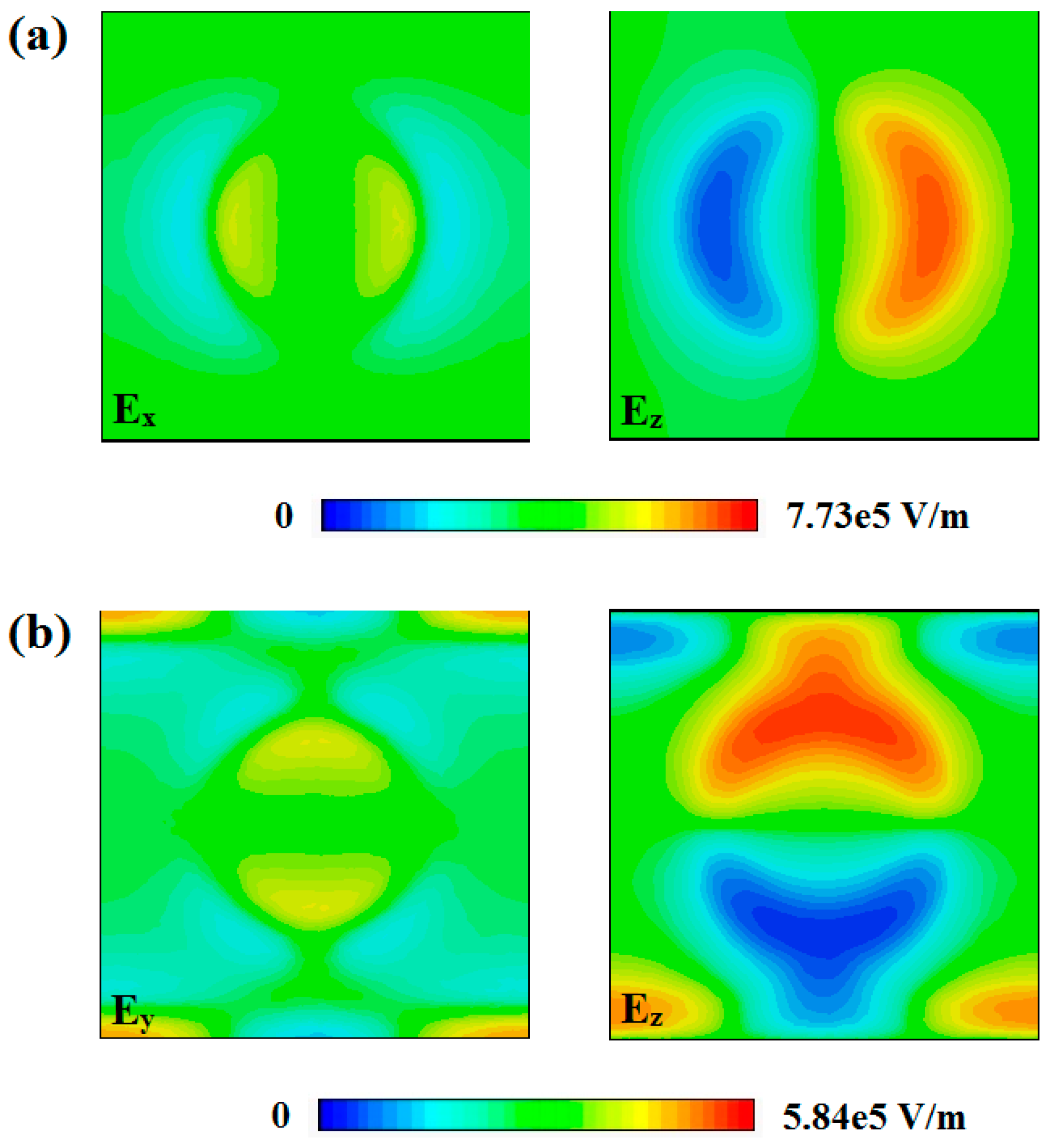
As shown in
Figure 2, it can be noticed that, for both TE- and TM-polarized wave incidences, the direction of the electric field vector in the LC layer is mainly parallel to the
z-axis, which is perpendicular to the direction of LC molecules. Hence, the LC permittivity is equal to ε
⊥ in the initial case (θ = 0°). With the increase in bias voltage applied on the LC layer, the LC permittivity increased to ε
|| in the fully biased state, and the reorientation angle of the LC molecule gradually shifted toward the
z-axis and was finally parallel to the
z-axis (θ = 90°).
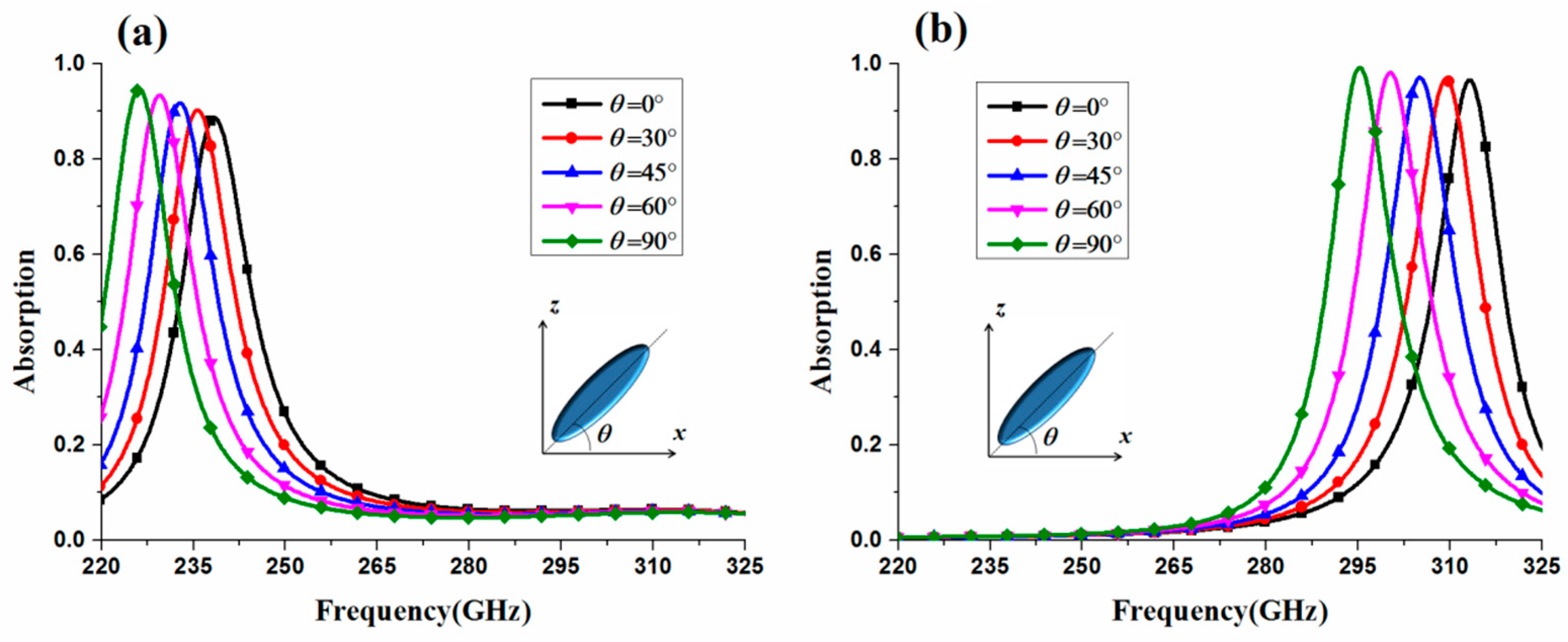
The absorption spectra for TE-polarized and TM-polarized normal incidence excitations for different LC director angles, which demonstrate the tunable performance of the proposed LC-based metamaterial absorber, were calculated and they are shown in
Figure 3. In
Figure 3, it can be seen that, as the LC director angle increases from 0 to 90°, the distinct peak absorption frequency for TE-polarized incidence changes from 238.4 to 226.1 GHz, with a frequency tunability (f
mod = Δf/f
max) of 5.1%. Meanwhile, a frequency tunability of 5.7% is achieved for TM-polarized incidence as the peak absorption frequency varies from 313.2 to 295.2 GHz. Moreover, it can also be seen in
Figure 3 that, for both TE-polarized and TM-polarized incidence excitations, absorptivity remains higher than 90% (except for the LC director angle of 0° for TE-polarization), so the proposed metamaterial absorber possesses high absorption within the entire tunable frequency region, a promising finding.
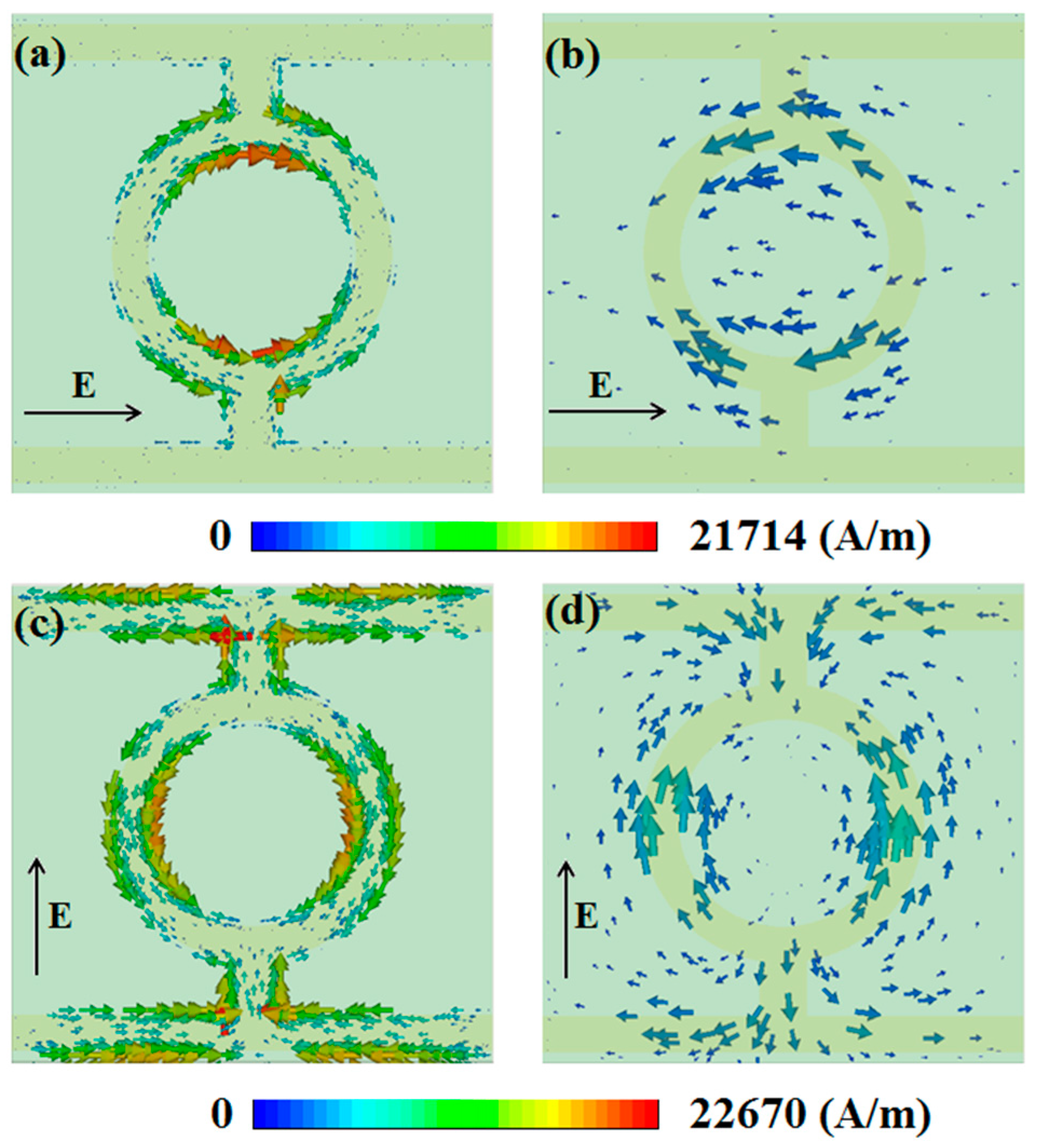
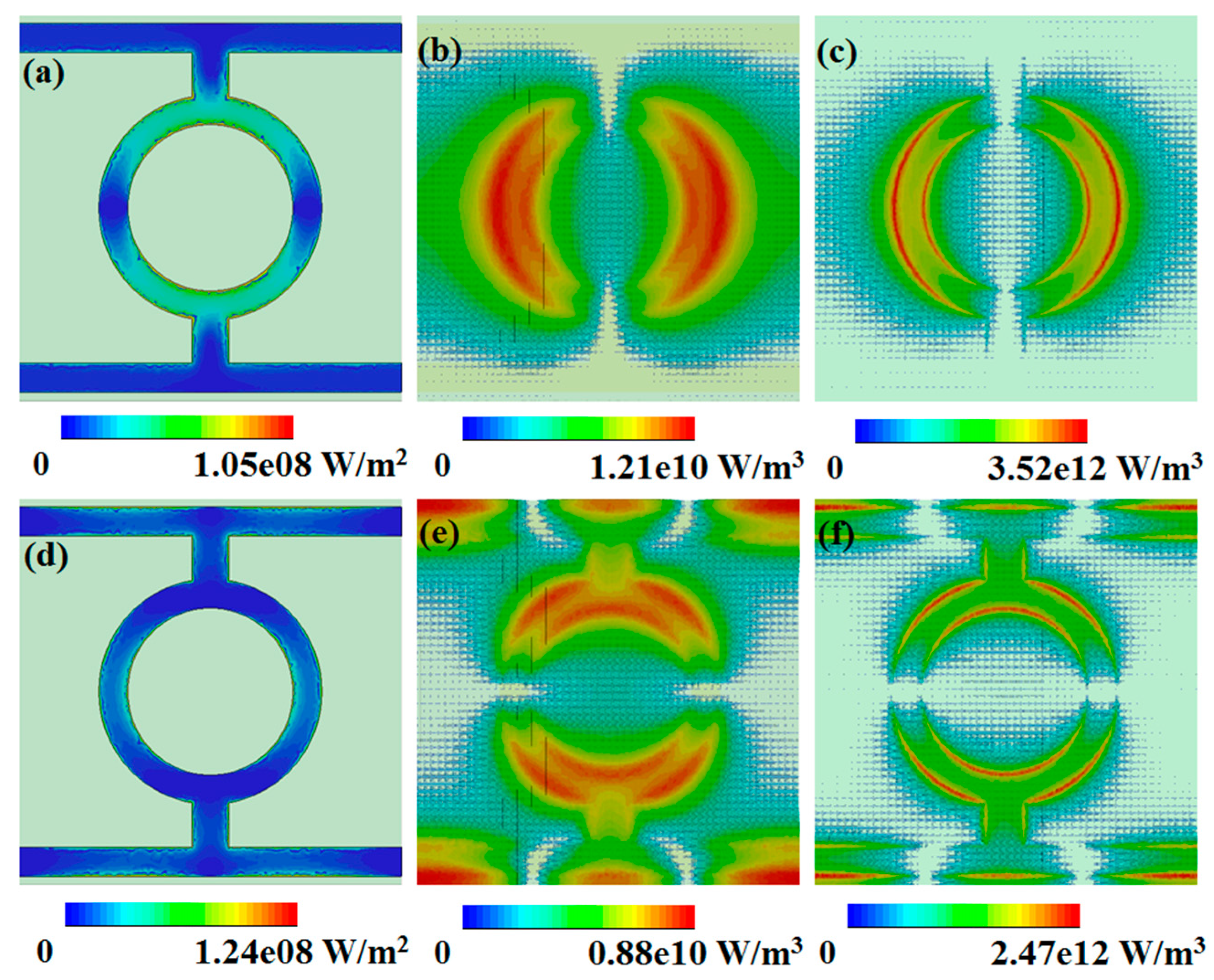
To explore the intrinsic mechanism of the absorber, the surface current distribution on the patterned copper layer and the copper ground plate for the TE-polarized and TM-polarized normal incidence excitations in the unbiased state was calculated and is illustrated in
Figure 4.
According to the results presented in
Figure 4a, it is obvious that the surface current on the copper pattern flows parallel to the direction of the electric field vector of TE-polarized incident wave. As a result, two electric dipole responses are excited in the patterned layer. Moreover, the surface current on the copper ground plate shown in
Figure 4b is the reverse of that in
Figure 4a, as the magnetic response is excited by circulating currents between the two metallic layers. For the TM-polarized incident wave, as shown in
Figure 4c, four dipoles are excited, and the electric response is mainly contributed by coupling interaction between these dipoles. Similarly, the surface current on the copper ground plane is reversed, and the magnetic response for TM-polarized incident wave is also excited by combining the copper pattern with the copper plate.
Furthermore, the ohmic losses at the patterned copper layer, as well as the power loss density in the quartz plate and the LC layer, for both the TE- and TM-polarized incident waves were calculated and are illustrated in
Figure 5. The dielectric loss distribution of the absorber is in agreement with the electric field distribution, and the ohmic loss distribution at the pattern surface is mainly determined by the surface currents. In addition, it can be observed that most of the energy in the absorber is dissipated in the LC layer, which contributes most of the power absorption under both TE- and TM-polarized normal incidences. Thus, the LC plays an important role not only in frequency tuning but also in the absorption of incident waves.
4. Absorption Spectrum Dependence on Geometrical Parameters and Incident Angle
In this section, the effect of the structure geometry on the absorption spectrum is analyzed. We suppose that only one parameter, e.g., the inner radius of the ring (r), the width of the vertical connecting bar (w), the width of the horizontal bar (b), or the gap between the horizontal bar and the edge of the unit cell (s), is changed, while the other dimensions are kept the same.
The simulation results for different r, w, b, and s values are presented in
Figure 6. As shown in
Figure 6a, with the increase in r, the resonance frequencies for both TE- and TM-polarized incident excitations are redshifted. An LC circuit mode for this metamaterial absorber is given by [
26]
The equivalent inductance L increases as r increases. It should be noticed that the increase in linewidth of metallic line leads to an increase in both the equivalent inductance L and the equivalent capacitance C. However, the increase in equivalent inductance L is much stronger that the equivalent capacitance C in this structure, as we mainly discussed the influence of equivalent inductance L in this section. According to Equation (3), the increased L leads to a redshift of the resonance frequency. It can be seen in
Figure 6a that the resonance frequency of TE-polarization, compared to that of TM-polarization, is more sensitive to r, which is because the resonance of TE-polarization is mainly concentrated in the ring area (
Figure 4a); as a result, the resonance frequency of TE-polarization is more dependent on r.
In
Figure 6b, it is shown that, for TE-polarization, the absorption peak shows a slight blueshift with the increase in w. This is because, in this case, w has little influence on the equivalent inductance L of the ring section. However, for TM-polarization, amplitude and frequency of the absorption peak are sensitive to the width w, which can be explained by the fact that equivalent inductance L of the vertical bar decreases with the increase in w.
Similarly, the increase in b leads to a decrease in the equivalent inductance L of the horizontal bar. Hence, the resonance frequency of TM-polarization is blueshifted (
Figure 6c). However, this does not affect the equivalent inductance L of the ring area, so the resonance frequency of TE-polarization remains the same.
The effect of the gap s on the absorption spectrum was also analyzed, and results are presented in
Figure 6d. As shown in
Figure 6d, the resonance frequency of TE-polarization is independent of the gap s. However, with the increase in s, the resonance frequency of TM-polarization shows a slight blueshift, which is caused by a decrease in equivalent inductance L.
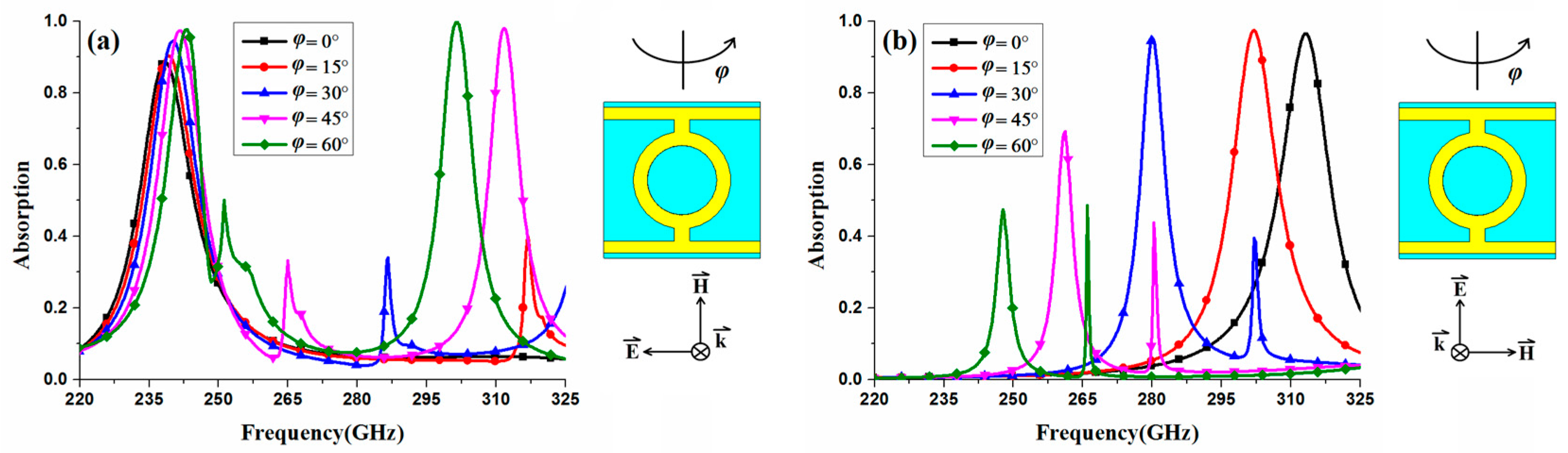
In addition, the absorber structure was analyzed theoretically for oblique incidence. The absorption spectrum for oblique incidence under the TE-polarized incident wave is shown in
Figure 7a. In this case, the magnetic field remains along the
y-axis and the direction of wave propagation is changed by an angle φ with respect to the
x and
z-axes.
Figure 7a shows a slight blueshift with the increase in incident angle and remains above 0.9 for an incident angle up to 60°. For oblique incidence under a TM-polarized incident wave, where the electric field is aligned towards the
y-axis and the wave propagation is changed by an angle φ with respect to
x and
z-axes, as presented in
Figure 7b, the absorption is almost unchanged for incident angles up to 30°. However, with the continuous increase in incident angle, the absorption decreases rapidly. Moreover, the increase in incident angle of the TM-polarized wave leads to an obvious redshift of the absorption peak, and a frequency tunability of 20.9% is achieved by increasing the incident angle from 0 to 60°, which represents another effective method of modulating the proposed structure.
5. Experimental Results
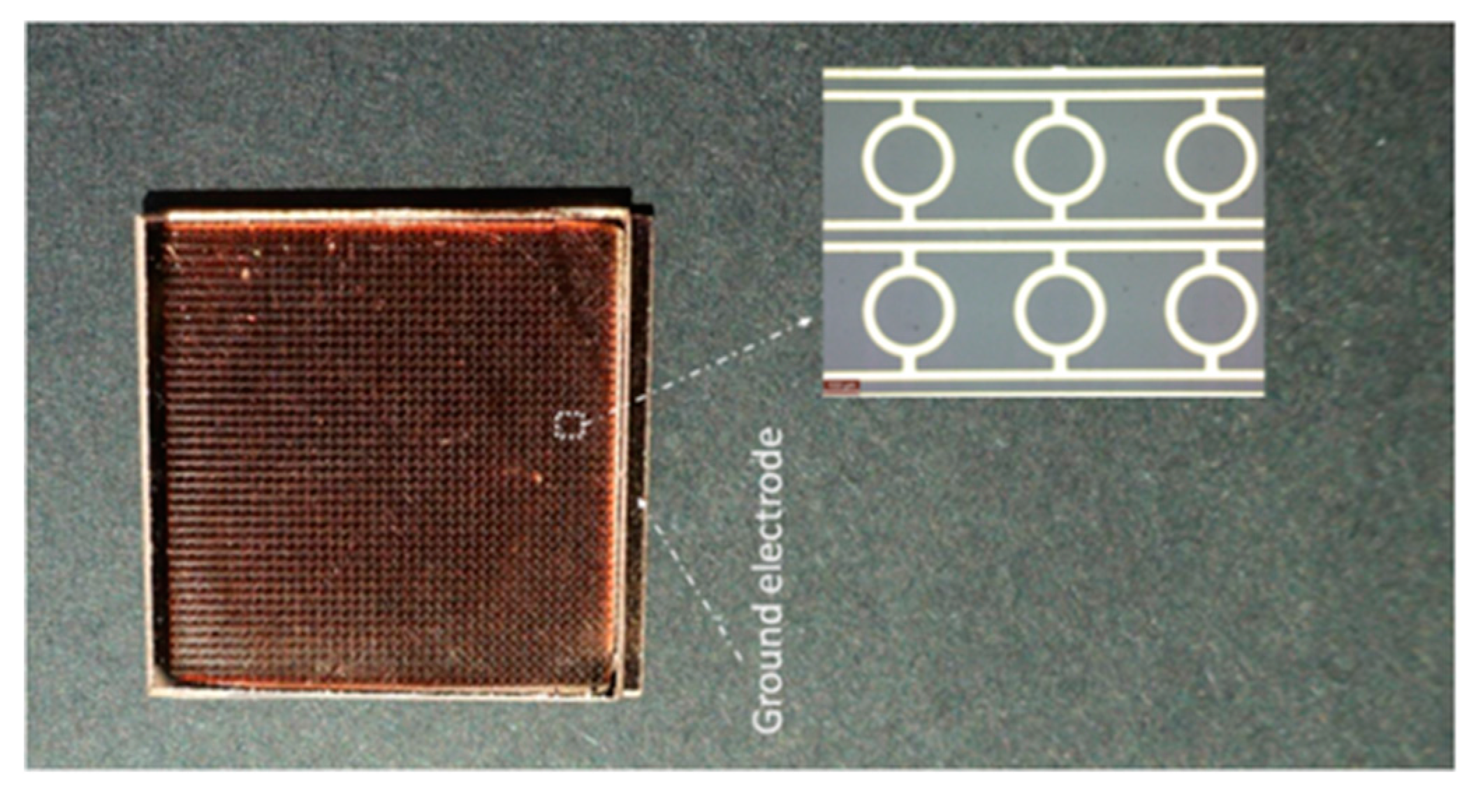
In this section, we experimentally validate the proposed metamaterial absorber presented in
Figure 1. The structure was fabricated using 2 × 2 cm
2 quartz substrates. To control the orientation of LC molecules in an unbiased state, the inner surfaces of metal layers were covered by polyimide (Pi) alignment layers. The LC cavity was created by placing the glass micropearls with the diameter of 45 μm between two wafers, which were then sealed by a thin film of epoxy resin. Lastly, liquid crystals were inserted into a 45 μm thick cavity. The fabricated sample is shown in
Figure 8.
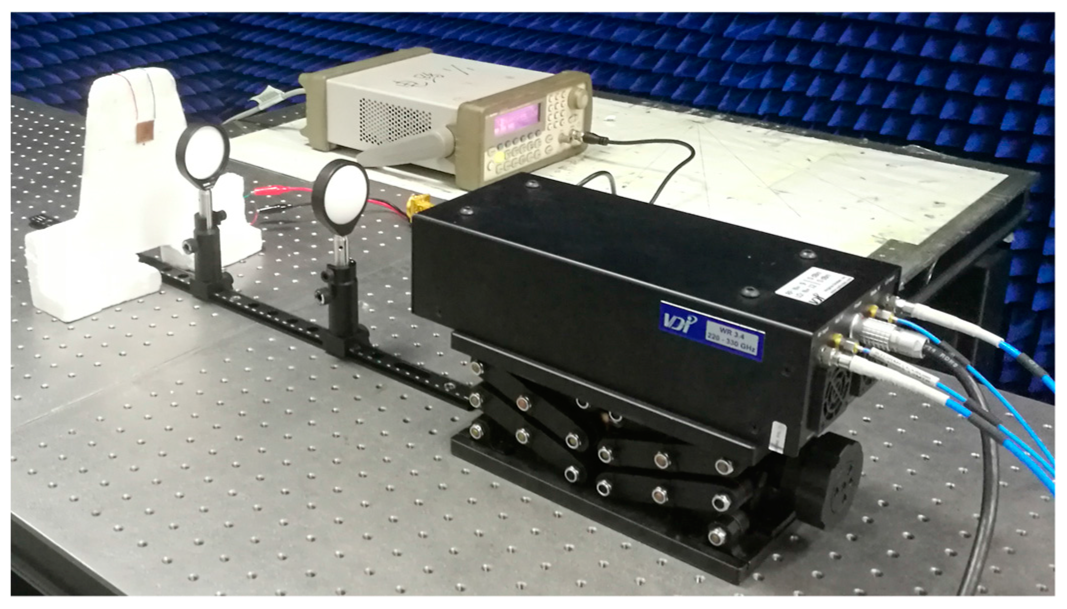
The measurement setup is presented in
Figure 9. The free space measurement method was adopted in the experiment. An antenna that was connected to the Agilent N5224A vector network analyzer via VNA extenders VDI VNAX592 was used to measure S-parameters in the frequency range 220–325 GHz. Moreover, a pair of THz lens was utilized to focus the THz beam.
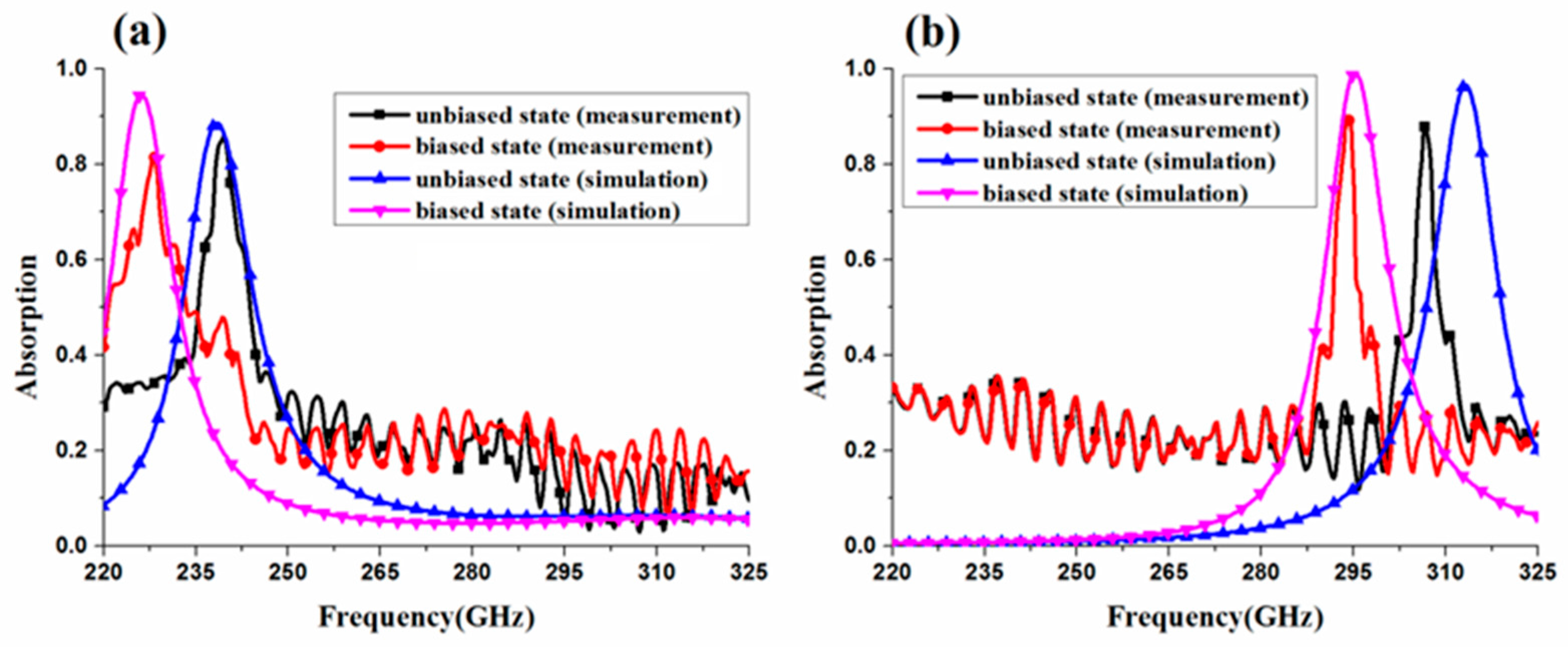
The measured absorption spectra at unbiased and full biased states for TE- and TM-polarization are given in
Figure 10. For TE-polarization,
Figure 10a, the frequency of the measured absorption peak in an unbiased state is in agreement with that in the simulation. However, in a biased state under TE-polarized incidence, the frequency of the measured absorption peak is higher than that in the simulation. For TM-polarization,
Figure 10b, there is a difference between the frequencies of the measured and simulated absorption peaks in an unbiased state, which might be caused by an inaccurate sample size, especially for structural parameters such as the width of vertical connecting bar w and the width of horizontal bar b.
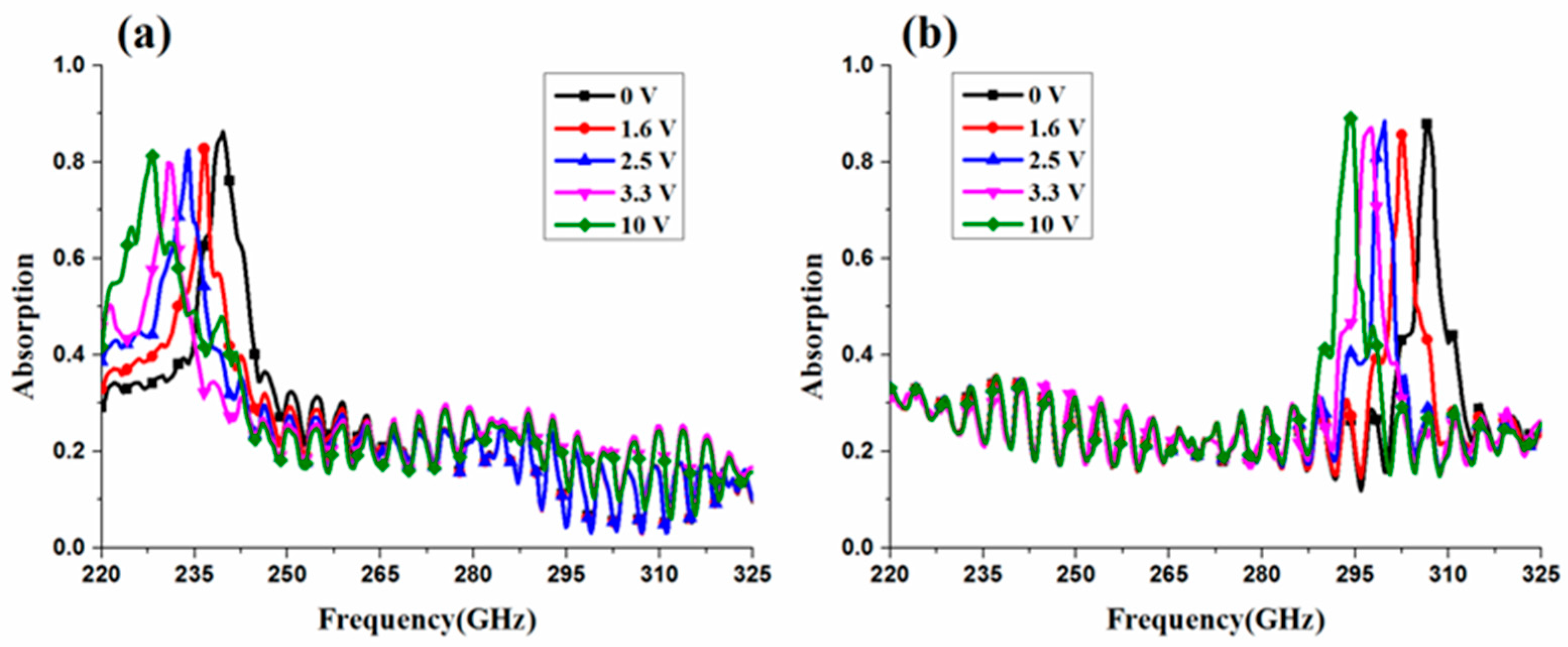
The frequency tunability was evaluated by measuring the absorption at different bias voltages of the LC layer. In
Figure 11a, when the bias voltage increases from 0 to 10 V, the resonance frequency of TE-polarization shifts from 239.5 to 228.1 GHz (redshift), with a frequency tunability of 4.7%. For TM-polarization, as shown in
Figure 11b, a frequency tunability of 4.1% is achieved when the absorption peak frequency decreases from 306.6 to 294 GHz. Moreover, for both TE- and TM-polarization, measured absorption is higher than 80% for all bias voltages.
6. Conclusions
In this paper, a tunable polarization-dependent metamaterial absorber based on LC intended for THz frequencies is presented, and both simulation and experiment were carried out to investigate the proposed structure. Intensive absorption peaks were experimentally detected at 239.5 GHz for a TE-polarized wave and at 306.6 GHz for a TM-polarized wave, when no bias voltage was applied. The absorption mechanism of the absorber was analyzed in terms of the surface current distribution and power loss distribution, and the effects of various geometrical parameters on absorption were investigated. Most importantly, by adjusting the bias voltage of the LC layer from 0 to 10 V, a frequency tunability of 4.7% for the TE-polarized wave and frequency tunability of 4.1% for a TM-polarized wave were experimentally demonstrated. Therefore, the presented tunable polarization-dependent metamaterial absorber has great potential in selective spectral detection, polarization multiplexing, and THz polarization imaging.

 ,
, 