Label Stacking Scenarios in Hybrid Wavelength and Code-Switched GMPLS Networks

School of Electrical and Computer Engineering, Nanfang College of Sun Yat-Sen University, Guangzhou 510970, China
Electronics 2018, 7(10), 251; https://doi.org/10.3390/electronics7100251
Submission received: 18 September 2018
/
Revised: 10 October 2018
/
Accepted: 12 October 2018
/
Published: 14 October 2018
(This article belongs to the Special Issue Optical Communications and Networks)
Abstract
:Multi-protocol label switching (MPLS) is a promising solution to implement high-speed internet protocol (IP) networks by reducing the layer number. To meet the increasing demand for data traffic, optical packet switching (OPS) is integrated under IP to provide high bandwidth to end users. Generalized MPLS (GMPLS) is perfectly compatible with the routing algorithm in IP/MPLS as it supports packet-switching functions. In this paper, we investigate the label stacking scenarios in GMPLS networks. In GMPLS, label stacking is done to reduce the node complexity by appending multiple labels to a single packet. Wavelength-division multiplexing (WDM) and optical code-division multiplexing (OCDM) signals have been widely used as identifying labels. As the labels can be permutated among the wavelengths or code dimensions, the structure of a label stack can be varied. However, studies on the relationship between label stacking scenarios and network performance are limited. To investigate this issue, we propose three label stacking models: sequential code distribution; sequential wavelength distribution, and random label distribution. The simulation results show that the sequential wavelength assignment, wherein the labels are uniformly distributed among the wavelengths, exhibits the best system performance in terms of the label-error rate (LER).
1. Introduction
Internet protocol (IP) is currently the most typical technology for transmitting multimedia information [1,2,3] with a hierarchical structure of multiple layers. These layers process the data packets in order, where the upper layer calls the lower one when completing the provided services. Due to the rapid increase in network traffic, an extended version of IP is required to support high bit-rate services for a large number of users. Multi-protocol label switching (MPLS), developed by Internet Engineering Task Force (IETF), is a promising solution to implement high-speed IP networks [4,5]. By reducing the layer number and the routing complexity, MPLS provides an efficient protocol for packet switching. The agreements in MPLS record the packet destination in the header and establish a pre-defined path between the start and the end point. During the packet propagation, the previous node identifies the label of the received packet and determines the node for setting up the next connection. Instead of analyzing the whole network, the intermediate nodes switch the packets by simply performing label recognition, which effectively saves processing time. As the complex routing algorithm is only calculated at the terminal nodes, the switching delay for an entire end-to-end route is greatly reduced.
Recently, IP services have extended to multiple high-bandwidth applications, such as IP television (IPTV) [6], voice over IP (VoIP) [7], and two-way video conferences [8]. To meet the increasing demand for data traffic, optical packet switching (OPS) [9,10,11] is integrated under IP to provide high bandwidth and signal reliability to end users. Similar to IP structure, OPS is a node-by-node network routing the optical packets through core nodes. Before entering the optical network, the packets are converted from electrical to optical domain by the optical edge nodes located in the boundary between IP and OPS. As OPS supports label-based functions, such as label generation and label processing, it is perfectly compatible with the routing algorithm in IP/MPLS.
Generalized multi-protocol label switching (GMPLS) is considered a future candidate for metropolitan area networks (MANs) and OPS [12,13,14]. By practically using the important parts of IP, GMPLS can provide a greater network capacity and flexible user traffic. The network forwards a packet to its destination by processing its labels to decide the switching path. During the switching procedure, the packet is preserved in the optical domain. The network expenses can be reduced by avoiding the costly operation of optical-to-electrical conversion in the routers.
Label stacking is a smart-switching criterion in GMPLS for fast and reliable transmission [15,16]. Label stacking and optical label swapping [17,18] are the two main methods used to switch packets through multiple network routers. For label swapping, each router recognizes the labeled packet and swaps the old appending label. Based on a look-up table, a newly created label is assigned to the packet before it is forwarded to the next router. Unlike label swapping wherein one packet carriers only one label at a time, label stacking assigns a stack of multiple labels to a single packet. The label stack includes all the information of the switching path. The routers can decide the correct switching path by simply checking the stacked labels. A simple backbone structure can be obtained by avoiding the repeated processing involved in label swapping and label creation in routers. As the number of labels in the stack is limited, the router can make the switching decision using the look-up table with a reduced size.
In typical GMPLS networks, wavelength division multiplexing (WDM) and optical code-division multiplexing (OCDM) schemes are employed to construct optical labels [17,18]. The label of a packet can be expressed as (W, C), where W and C denote the WDM channel and the code used for transmitting the packet data, respectively. In this approach, each WDM channel is shared by multiple OCDM labels. The packet is forwarded via an end-to-end route comprising multiple routers and connected paths between the routers. A label distribution protocol (LDP) helps decide the label corresponding to each intermediate path. For a given route, there are several combinations of assigned labels provided by the LDP.
The scenarios of label distribution significantly affect the network performance in label switching systems. In Reference [17], multi-service transmission was realized by modifying the number of OCDM labels among WDM channels. In another study [18], the effects of different labeling schemes on a hybrid wavelength/code buffering structure were evaluated. To obtain the best performance, the router intelligently converts the wavelength of the label into a new one with the least occupied OCDM labels. However, only label swapping schemes have been discussed in the above studies. For GMPLS networks with label stacking, the relationship between the label distribution scenarios and the network performance is rarely studied.
In this paper, we propose label stacking scenarios to provide packet switching service in hybrid wavelength and code-switched GMPLS networks. Unlike previous studies, this study focuses on the relationship between label distribution methods and network performance. As the labels can be permutated among the wavelengths or code dimensions, the structure of a label stack can be varied. We propose three representative label stacking models: sequential code distribution; sequential wavelength distribution, and random label distribution. We perform numerical simulations to compare the effectiveness of the three labeling schemes. The system performance is evaluated in terms of the label-error rate (LER) by analyzing the power spectral density (PSD) of the label distribution models.
2. Related Work
Combining the advantages of IP and OPS, GMPLS enables the nodes to execute packet switching in time, wavelength, and space domain [19,20,21,22,23]. Multiple optical labeling schemes have been proposed as the replacements for the conventional modules of electrical header processing. The available methods of generating optical labels include on–off keying (OOK) [19], frequency-shift keying (FSK) [20], and bit staking [21]. Except for the above scenarios, wavelength division multiplexing (WDM) also plays a significant role in integrating MPLS over optical layers [22,23]. In wavelength switching, the label expressed as the signal wavelength is analyzed to determine the switching path of the packets. After the previous label is identified, it is swapped for a new one by changing the wavelength of the received signal. Although employing WDM labels reduces the complexity of deploying all-optical networking and supports high-speed packet switching, some challenges remain unsolved. For example, during the entire packet interval, only a single wavelength is used throughout the label bandwidth, resulting in the reduction of bandwidth efficiency.
Multi-wavelength signals are another solution to implement optical labels as they are efficient in bandwidth utilization [24] and compatible with label stacking [25]. Such labels achieve relatively high switching speed while controlling the cost within an acceptable range. The Label of an optical packet consists of multiple wavelengths based on the label structure, for example, weight-2 labels [25]. The address information is firstly encoded on the spectrum of the optical signal, before appending the multi-wavelength label to a packet.
Optical code labeling (OCL), mapping the packet address onto the label through optically encoding, is proposed as a promising labeling method in GMPLS networks [26,27,28]. Optical code is employed to switch data flows based on a multiplexing technique known as optical code-division multiple access (OCDMA) [29,30,31,32,33]. The speed limitation of processing a label code is overcome by avoiding executing optical-to-electrical conversion at core nodes. In References [26,27], optical carries were modulated with orthogonal optical codes generated from an optical encoder based on array waveguide grating (AWG). Authors of Reference [28] had experimented recognizing the labels of optical codes using an optical correlator made up of passive optical components. The incoming code was correlated with all available codes to calculate the correlation results for identifying the received label.
3. Label Stacking in Hybrid Wavelength and Code-Switched GMPLS Network
The hybrid wavelength and code-switching technique employed in GMPLS networks helps increase the packet switching speed and reduce the complexity of performing all-optical networking. In this approach, the identifying label (expressed as optical codes and wavelength signals) are used to switch the packet through multiple paths. We classify the fiber waveband into several WDM channels and assign multiple optical codes to each of them. Figure 1 shows the classification scheme of the hybrid code/wavelength labels. In this figure, M denotes the number of channels, and N denotes the number of codes multiplexed in a channel. Accordingly, the total number of available labels (L) can be obtained as L = M × N.
The switching mechanisms in the proposed GMPLS network are supported by the label stacking technique. In such a network, the LDP maps each connection between the nodes to a specific label. At the network input, an edge router (ER) is used to determine the label switched path (LSP) of the transmitted packets based on their destinations. All the labels corresponding to the connections in the LSP are included in a label stack. The ER labels the packets with the stack and sends the packets to the next core router (CR). To perform packet switching, CRs recognize the received label stack by identifying its codes and wavelengths. The outgoing path is determined based on the decoding and de-multiplexing results of the stacked labels.
Figure 2 shows the label stacking scheme in an exemplary GMPLS network with two LSPs. In LSP1, the packets are labeled as (W1, C1), (W1, C2), and (W3, C1). CR1 switches the packets along LSP1 by identifying (W1, C1) in the stack using the method proposed in Reference [30]. Similarly, CR2 and CR3 forward the packets by realizing the labels (W1, C2) and (W3, C1), respectively. In this network, each CR only processes label recognition, and the packets are switched without swapping their labels.
4. Methods of Stacking Hybrid Wavelength/Code Labels
4.1. Sequential Code Distribution
In this approach, the labels are sequentially assigned to the connections in an LSP based on the code index i, where 1 ≤ i ≤ N. When (W1, C1) is assigned to a connection, the label (W2, C1) allocated to the same WDM channel is selected for the next connection. When all N labels in the first WDM channel W1 are occupied, the labels in the second WDM channel, i.e., (W2, C1), (W2, C1)…, are sequentially assigned to the remaining connections, as shown in Figure 3a. In this scenario, most labels are stacked in a few WDM channels. Figure 3b shows the PSD of the stacked labels of the sequential code distribution. When a new label is assigned to the stack, an unused code in the same WDM channel is selected. In this example, most of the occupied labels are distributed in the channels of W1 and W2.
4.2. Sequential Wavelength Distribution
In this scenario, when (Wi, Cj) is occupied by a node, the label (Wi+1, Cj) is sequentially chosen for the next connection, where 1 ≤ i ≤ M − 1 and 1 ≤ j ≤ N. Figure 4a shows the mapping of the labels to the path connections. As for the structure of the label stack, for example, when (W1, C1) is chosen, (W2, C1) is assigned to the stack. Similarly, this procedure is repeated for (W3, C1), (W4, C1)…(WM, C1) until all the channels have exactly one label. Subsequently, (W1, C2), (W2, C2)…are assigned to the remaining nodes in a proper order. In this scenario, the channels have similar label numbers, as shown in Figure 4b. When a new label is stacked, the one with the same code index as the previous label is selected.
5. Network Performance Analysis
In this section, we perform numerical simulations to evaluate the system performance in terms of the LER. To detect a specific hybrid WDM/OCDM label from the stack, both de-multiplexing and decoding processes are required. A nearly ideal de-multiplexing can be performed by simply using an optical band-pass filter. As for the decoding, multiple access interference (MAI) should be considered, as the target label and the others are multiplexed in the same WDM channel. The OCDM technique with spectral amplitude coding (SAC) [31] is employed, as it can eliminate MAI. The desired SAC label can be recovered without the influence of MAI using designated signature codes and balanced detection [32]. The factors affecting the performance of SAC systems are noise sources such as thermal noise, shot noise, and phase-intensity-induced noise (PIIN). Therefore, we can define the LER of the SAC labels as follows:
where erfc(·) denotes the complementary error function, Ip denotes the photocurrent in Ampere, denotes the variance of thermal noise defined in [32], denotes the variance of PIIN, and denotes the variance of shot noise. According to the definition given in Reference [32], the received PSD of the stacked labels at the decoder must be given to obtain and .
For simplicity, we assume that the PSD of the un-encoded light source is flat and un-polarized, and the central wavelength of the first WDM channel is shifted to λc = v/2M, where v is the width of the light spectrum. Assuming the jth label code vector Cj = [cj(1), cj(2)…cj(N)], where cj(h) is the hth chip of Cj and 1 ≤ h ≤ N, the PSD of a single SAC label (W1, C1) is obtained, as shown in Figure 5. In this figure, the optical spectrum with bandwidth v is occupied by M WDM channels, and each channel is sliced into N wavebands with a width of v/MN. The wavebands with a pulse correspond to the chip “1s” in Cj, whereas the chip “0s” corresponds to the bands with zero power.
In the following analysis, we assume that (W1, C1) is the target label to be identified. Therefore, the decoder only processes the stacked labels in W1, and the signals allocated to the other WDM channels are filtered out. Based on Figure 5, the PSD of the stacked SAC labels in W1 can be mathematically expressed as follows:
where P is the received optical power, and K1 is the stacked label number in W1. The symbol represents the rectangle function centered at λ and with a width of v/MN. For SAC labels using M-sequence codes [33], the photocurrent Ip of the decoded label (W1, C1) can be obtained as follows:
where R is the responsivity of the photo-diode and is the two’s complement of c1(h). The variances of the shot noise and PIIN can be expressed as follows:
where B is the electrical bandwidth of the decoder, and e is the electron charge in Coulomb. However, for a network system with K stacked labels, the labels in W1 for the two distribution scenarios have different quantities, which can be described as follows:
where denotes the floor function. Furthermore, we introduce the third scenario called random label distribution. In this scenario, except for (W1, C1), the other K − 1 labels are randomly selected from the M × N labels in the label domain. The expected label number K1 for random label distribution in the first WDM channel W1 can be expressed as follows:
6. Simulation Results and Discussion
Figure 6 compares the LERs of the three label stacking scenarios in the GMPLS network for hybrid labels; here, (M, N) = (8, 31) and (M, N) = (4, 63). The parameters used for the simulations are the received power (P = −10 dbm), photo-diode responsivity (R = 0.81 A/W), and electrical bandwidth (B = 80 MHz). The LER of the sequential wavelength distribution is better than those of the sequential code distribution and random label distribution. This is because distributing all the labels among the wavelengths helps reduce the number of overlapping labels in the WDM channel, resulting in a lower noise variance. The system performance reduces when K1 is high, where PIIN variance is high. Given a fixed K, M = 4 is better than the case of M = 2, as the label number in channel W1 is lower. In addition, this figure shows the LER of the standard SAC labels, which can be expressed as the hybrid label in a single WDM channel (M = 1, N = 255). The SAC outperforms the sequential code distribution as the label stack is encoded in the entire bandwidth rather than the narrow WDM channels. However, its performance still cannot compete with the proposed scenario of sequential wavelength distribution.
Figure 7 shows the effect of the received optical power on the system LER for K = 80 and (M, N) = (8, 31). The LERs of the random label distribution and sequential wavelength distribution decrease with the increase in the received power. In the two cases, the stacked label numbers are relatively low, and the main factors affecting the LER are the thermal and shot noises. The two noise sources can be mitigated by increasing the intensity of the photocurrent. However, this tendency is not evident for the sequential code distribution and SAC labels, wherein the PIIN effect is considerable because of the high stacked label number, K1 = 31 and 80, respectively. As the variance of PIIN is proportional to the signal power, the LER cannot be reduced by simply employing a high-intensity light source.
Figure 8 shows the LERs of the three stacking scenarios with respect to the number of WDM channels. The label number is 120. The stacking schemes with a higher M are found to exhibit better LERs. This is because of the fewer labels stacked in the WDM channels. Moreover, the sequential wavelength assignment once again outperforms the other two in terms of the LER, which is consistent with the results shown in Figure 6. The performance of the stacked SAC labels is not investigated in this figure, as the channel number M is always fixed to 1.
7. Conclusions and Future Works
In this paper, we investigated the label stacking scenarios in a hybrid wavelength and code-switched GMPLS network. The relationship between the label stacking structure and the network performance was studied in terms of the LER. The simulation results showed that the LER performance of the sequential wavelength distribution is better than those of the random label distribution and sequential code distribution. Equivalently spreading the labels over the WDM channels in the optical spectrum helps reduce the label number in a single channel, resulting in a lower noise variance. Therefore, better LER results could be achieved by assigning each channel with similar label numbers. Finally, the effects of the label power and channel number on the network LER performance were analyzed. Results reveal the stacking schemes with a large channel number are found to exhibit better LERs. The LER of sequential wavelength distribution can be further improved by employing a high-intensity light source.
Evaluating the spectral efficiency in the proposed scenarios of label distribution is an exciting topic for future works. Based on the conclusion, the sequential wavelength distribution always has the best performance, but its label stack occupies a larger bandwidth when K ≤ N. Analyzing the tradeoff between LER and spectral efficiency would give an adequate depiction of the proposed network. In addition, instead of M-sequence codes used in the paper, some of SAC codes with beneficial characteristics have been employed in conventional OCDMA networks to reach small error probabilities. Exploiting other codes for constructing hybrid labels is another critical subject for further improving the proposed idea.
Funding
This research received no external funding.
Conflicts of Interest
The author declares no conflict of interest.
References
- Dey, S.K.; Adhya, A. IP-over-WDM network design methodology to improve efficiency in overall expenditure due to cost and energy consumption. IEEE/OSA J. Opt. Commun. Networking 2015, 7, 563–577. [Google Scholar] [CrossRef]
- Zhang, X.; Xu, L. Energy-efficient traffic grooming under sliding scheduled traffic model for IP over WDM optical networks. China Commun. 2014, 11, 74–83. [Google Scholar] [CrossRef]
- Beletsioti, G.A.; Papadimitriou, G.I.; Nicopolitidis, P. Energy-aware algorithms for IP over WDM optical networks. J. Lightw. Technol. 2016, 34, 2856–2866. [Google Scholar] [CrossRef]
- Kadohata, A.; Tanaka, T.; Watanabe, A.; Hirano, A.; Hasegawa, H.; Sato, K. Differential reliability path accommodation design and reconfiguration in virtualized multi-layer transport network. IEICE Trans. Commun. 2015, 98, 2151–2159. [Google Scholar] [CrossRef]
- Teruaki, Y.; Katsuyoshi, I.; Hiroyuki, K.; Suguru, Y. Proposal for adaptive bandwidth allocation using one-way feedback control for MPLS networks. IEICE Trans. Commun. 2007, 90, 3530–3540. [Google Scholar]
- Gao, Y.; Wei, X.; Zhang, X.; Zhuang, W. A combinational LDA-based topic model for user interest inference of energy efficient IPTV service in smart building. IEEE Access 2018, 6, 48921–48933. [Google Scholar] [CrossRef]
- Tian, H.; Sun, J.; Chang, C.; Huang, Y.; Chen, Y. Detecting bitrate modulation-based covert voice-over-IP communication. IEEE Commun. Lett. 2018, 22, 1196–1199. [Google Scholar] [CrossRef]
- Northwood, C.; Wadge, R. An architecture for cloud-based IP video production tools. SMPTE Motion Imaging J. 2018, 127, 32–37. [Google Scholar] [CrossRef]
- Fiorani, M.; Casoni, M.; Aleksic, S. Hybrid optical switching for an energy-efficient internet core. IEEE Internet Comput. 2013, 17, 14–22. [Google Scholar] [CrossRef]
- Osadchiy, A.V.; Guerrero, N.; Jensen, J.B.; Monroy, I.T. Coherent spectral amplitude coded label detection for DQPSK payload signals in packet -switched metropolitan area networks. Opt. Fiber Technol. 2011, 17, 141–144. [Google Scholar] [CrossRef]
- Yoo, S.J.B. Energy efficiency in the future internet: the role of optical packet switching and optical-label switching. IEEE J. Sel. Top. Quantum Electron. 2011, 17, 406–418. [Google Scholar] [CrossRef]
- Kanj, M.; Rouzic, E.L.; Meuric, J.; Cousin, B.; Amar, D. Optical power control in GMPLS control plane. IEEE/OSA J. Opt. Commun. Networking 2016, 8, 553–568. [Google Scholar] [CrossRef]
- Farghal, A.E.; Shalaby, H.M.H.; Kawasaki, Z. Multirate multiservice all-optical code switched GMPLS core network utilizing multicode variable-weight optical code-division multiplexing. IEEE/OSA J. Opt. Commun. Networking 2014, 6, 670–683. [Google Scholar] [CrossRef]
- Beyranvand, H.; Salehi, J.A. All-optical multiservice path switching in optical code switched GMPLS core networks. J. Lightwave Technol. 2009, 27, 2001–2012. [Google Scholar] [CrossRef]
- Seddighian, P.; Ayotte, S.; Rosas-Fernandez, J.B.; Penon, J.; Rusch, L.A.; LaRochelle, S. Label stacking in photonic packet-switched networks with spectral amplitude code labels. J. Lightwave Technol. 2007, 25, 463–471. [Google Scholar] [CrossRef]
- Chen, K.S.; Yang, C.C.; Huang, J.F. Using stuffed quadratic congruence codes for SAC labels in optical packet switching network. IEEE Commun. Lett. 2015, 19, 1093–1096. [Google Scholar] [CrossRef]
- Beyranvand, H.; Salehi, J.A. Multiservice provisioning and quality of service guarantee in WDM optical code switched GMPLS core networks. J. Lightwave Technol. 2009, 27, 1754–1762. [Google Scholar] [CrossRef]
- Kazemi, R.; Rashidinejad, A.; Nashtaali, D.; Salehi, J.A. Virtual optical buffers: a novel interpretation of OCDMA in packet switch networks. J. Lightwave Technol. 2012, 30, 2964–2975. [Google Scholar] [CrossRef]
- Lin, Y.M.; Yuang, M.C.; Lee, S.L.; Way, W.I. Using superimposed ASK label in a 10-Gb/s multi-hop all-optical label swapping system. J. Lightwave Technol. 2014, 22, 351–361. [Google Scholar] [CrossRef]
- Lallas, E.N.; Skarmoutsos, N.; Syvridis, D. Coherent encoding of optical FSK header for all optical label swapping systems. J. Lightwave Technol. 2005, 23, 1199–1209. [Google Scholar] [CrossRef]
- Willner, A.E.; Gurkan, D.; Sahin, A.B.; McGeehan, J.E.; Hauer, M.C. All-optical address recognition for optically-assisted routing in next-generation optical networks. IEEE Commun. Mag. 2003, 41, 38–44. [Google Scholar] [CrossRef]
- Xu, R.; Gong, Q.; Ye, P. A novel IP with MPLS over WDM-based broad-band wavelength switched IP network. J. Lightwave Technol. 2001, 19, 596–602. [Google Scholar]
- Alshaer, H.; Elmirghani, J.M.H. Multilayer dynamic traffic grooming with constrained differentiated resilience in IP/MPLS-over-WDM networks. IEEE Trans. Netw. Serv. Manage. 2012, 9, 60–72. [Google Scholar] [CrossRef]
- Habib, C.; Baby, V.; Chen, L.R.; Delisle-Simard, A.; LaRochelle, S. All-optical swapping of spectral amplitude code labels using nonlinear media and semiconductor fiber ring lasers. IEEE J. Sel. Top. Quantum Electron. 2008, 14, 879–888. [Google Scholar] [CrossRef]
- M’Sallem, Y.B.; Seddighian, P.; Rusch, L.A.; LaRochelle, S. Optical packet switching via FWM processing of time-stacked weight-2 codes. IEEE Photonics Technol. Lett. 2008, 20, 1712–1714. [Google Scholar] [CrossRef]
- Cincotti, G.; Naoya, W.; Kitayama, K. Characterization of a full encoder/decoder in the AWG configuration for code-based photonic routers—Part I: Modeling and design. J. Lightwave Technol. 2006, 24, 103–112. [Google Scholar] [CrossRef]
- Naoya, W.; Cincotti, G.; Yoshima, S.; Kataoka, N.; Kitayama, K. Characterization of a full encoder/decoder in the AWG configuration for code-based photonic routers—Part II: Experiments and applications. J. Lightwave Technol. 2006, 24, 113–121. [Google Scholar] [CrossRef]
- El-Sahn, Z.A.; Shastri, B.J.; Zeng, M.; Kheder, N.; Plant, D.V.; Rusch, L.A. Experimental demonstration of a SAC-OCDMA PON with burst-mode reception: Local versus centralized sources. J. Lightwave Technol. 2008, 26, 1192–1203. [Google Scholar] [CrossRef]
- Yang, C.C.; Chen, K.S.; Huang, J.F.; Kuo, J.C. Differential service in a bidirectional radio-over-fiber system over a spectral-amplitude-coding OCDMA network. Photonics 2016, 3, 53. [Google Scholar] [CrossRef]
- Yang, C.C. Hybrid wavelength-division-multiplexing/spectral-amplitude-coding optical CDMA system. IEEE Photonics Technol. Lett. 2005, 17, 1343–1345. [Google Scholar] [CrossRef]
- Noshad, M.; Jamshidi, K. Bounds for the BER of codes with fixed cross correlation in SAC-OCDMA systems. J. Lightwave Technol. 2011, 30, 1944–1950. [Google Scholar] [CrossRef]
- Wei, Z.; Shalaby, H.M.H.; Ghafouri-Shiraz, H. Modified quadratic congruence codes for fiber bragg-grating-based spectral-amplitude-coding optical CDMA systems. J. Lightwave Technol. 2001, 19, 1274–1281. [Google Scholar]
- Yang, C.C.; Huang, J.F.; Tseng, S.P. Optical CDMA network codecs structured with M-sequence codes over waveguide-grating routers. IEEE Photonics Technol. Lett. 2004, 16, 641–643. [Google Scholar] [CrossRef]
Figure 1.
Classification of the wavelength-division multiplexing (WDM)/ optical code-division multiplexing (OCDM) labels.
Figure 1.
Classification of the wavelength-division multiplexing (WDM)/ optical code-division multiplexing (OCDM) labels.
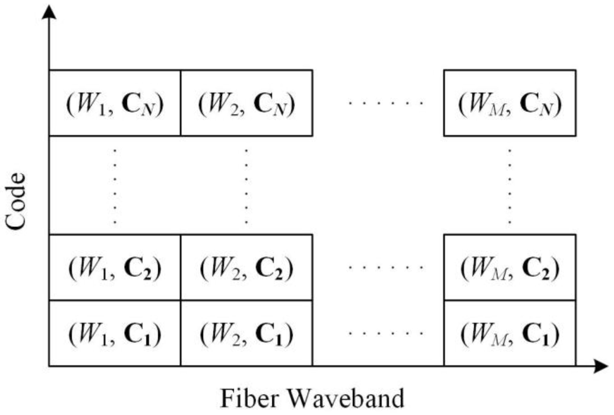
Figure 2.
Label stacking in hybrid wavelength and code-switched generalized multi-protocol label switching (GMPLS) network.
Figure 2.
Label stacking in hybrid wavelength and code-switched generalized multi-protocol label switching (GMPLS) network.
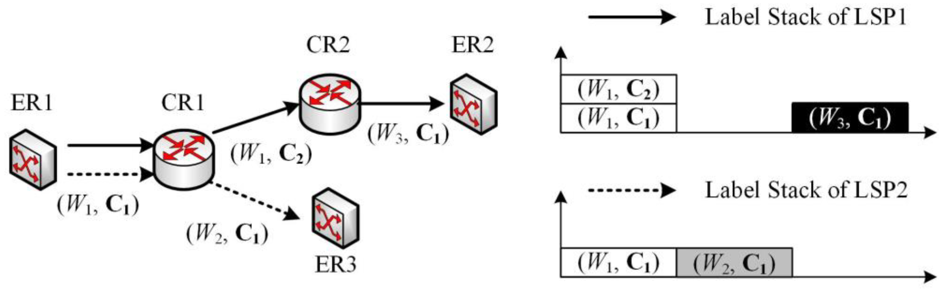
Figure 3.
Sequential code distribution: (a) label assignment to the label switched path (LSP), (b) power spectral density (PSD) of the stacked labels.
Figure 3.
Sequential code distribution: (a) label assignment to the label switched path (LSP), (b) power spectral density (PSD) of the stacked labels.
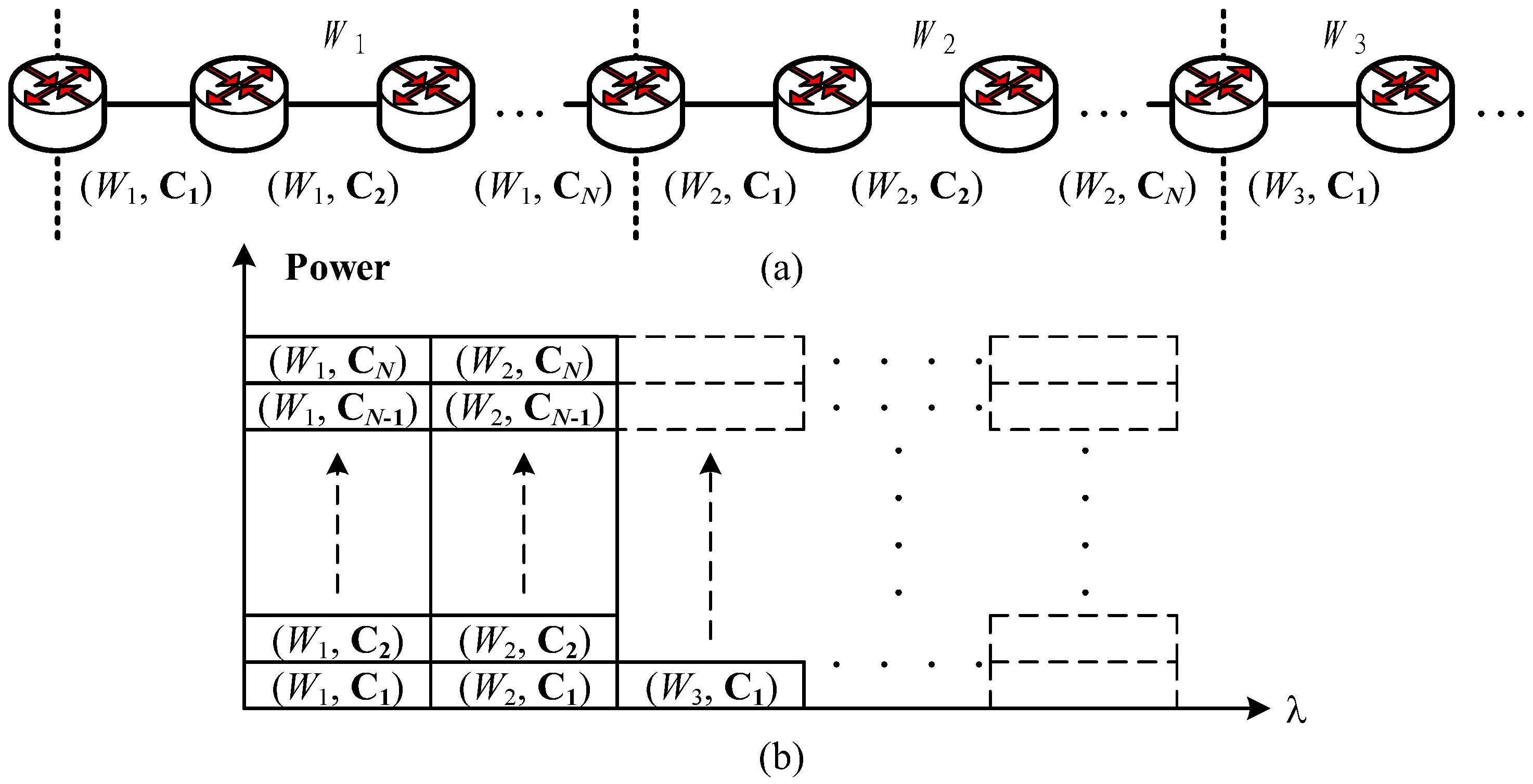
Figure 4.
Sequential wavelength distribution: (a) label assignment to LSP, (b) PSD of the stacked labels.
Figure 4.
Sequential wavelength distribution: (a) label assignment to LSP, (b) PSD of the stacked labels.

Figure 5.
PSD of a single spectral amplitude coding (SAC) label (W1, C1).

Figure 6.
Label-error rate (LER) versus K1 for the three label stacking scenarios. C: sequential code assignment; W: sequential wavelength assignment; R: random label assignment.
Figure 6.
Label-error rate (LER) versus K1 for the three label stacking scenarios. C: sequential code assignment; W: sequential wavelength assignment; R: random label assignment.
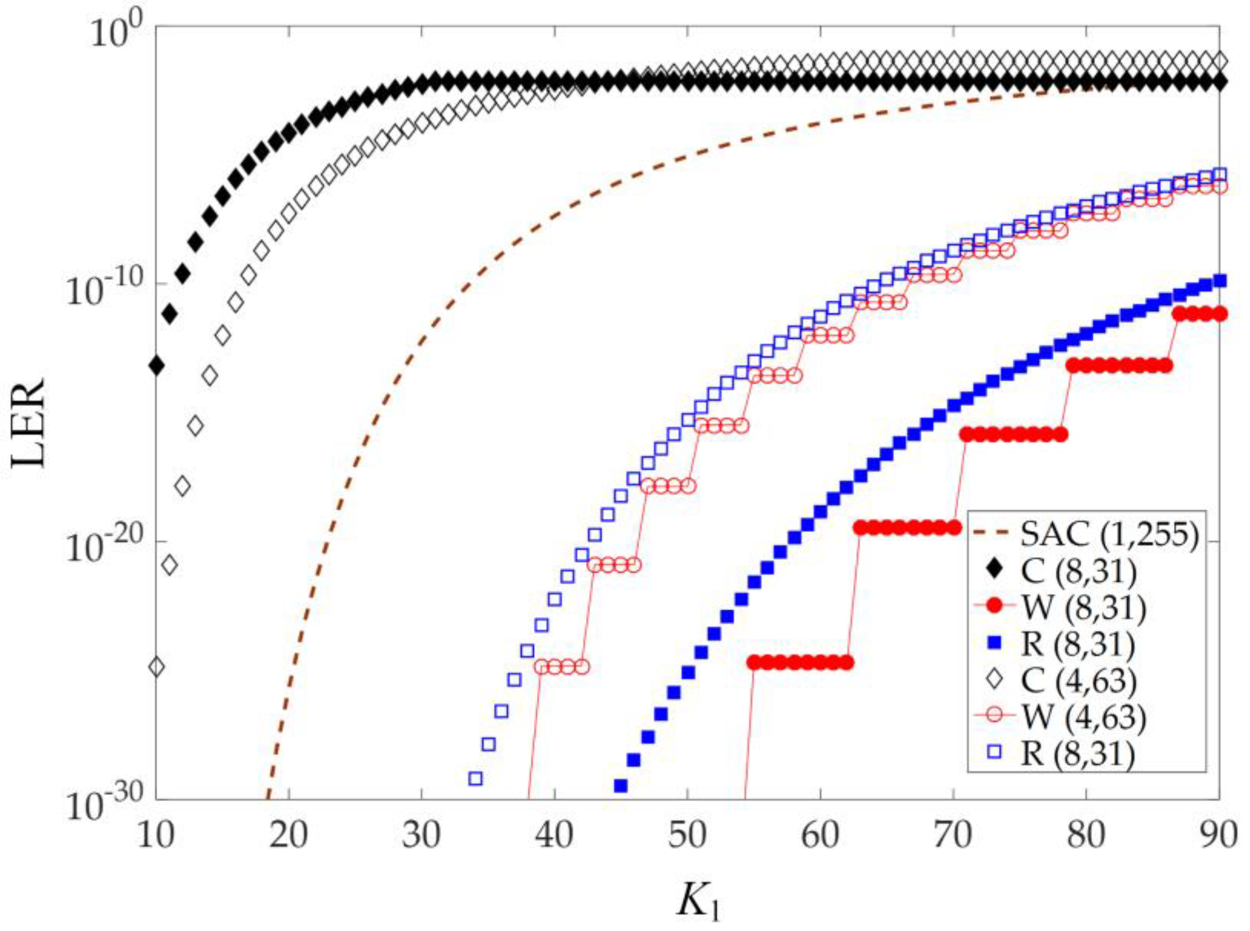
Figure 7.
LER versus P for the three label stacking scenarios.

Figure 8.
LER versus WDM channel number M. for the three label stacking scenarios.

© 2018 by the author. Licensee MDPI, Basel, Switzerland. This article is an open access article distributed under the terms and conditions of the Creative Commons Attribution (CC BY) license (http://creativecommons.org/licenses/by/4.0/).
Share and Cite
MDPI and ACS Style
Chen, K.-S. Label Stacking Scenarios in Hybrid Wavelength and Code-Switched GMPLS Networks. Electronics 2018, 7, 251. https://doi.org/10.3390/electronics7100251
AMA Style
Chen K-S. Label Stacking Scenarios in Hybrid Wavelength and Code-Switched GMPLS Networks. Electronics. 2018; 7(10):251. https://doi.org/10.3390/electronics7100251
Chicago/Turabian StyleChen, Kai-Sheng. 2018. "Label Stacking Scenarios in Hybrid Wavelength and Code-Switched GMPLS Networks" Electronics 7, no. 10: 251. https://doi.org/10.3390/electronics7100251
Note that from the first issue of 2016, this journal uses article numbers instead of page numbers. See further details here.