1. Introduction
A primary purpose of the smart grid is to deploy digital communication networks (e.g., Ethernet, cellular service and satellite signal) to enable data acquisition and remote control between control centers and the large number of power grid facilities (e.g., substations and power plants). Due to the installation of intelligent electronic devices (IEDs) on power grids, power system operators are able to monitor and control a power system from a remote control center. These remote control and monitoring technologies are based on information and communications technology (ICT). As a result, vulnerabilities with respect to cyber intrusions also become a serious concern.
A massive cyber attack occurred on Ukraine’s power system in December 2015. More than ten thousand homes and facilities experienced a power outage for hours, even days. This attack was enabled by a malware called BlackEnergy installed on the control center computers [
1]. This cyber intrusion event shows that attackers can damage a large-scale ICT network in a short time. In addition, cyber intruders, compared to physical intrusion events, are hard to locate. Cyber attackers can be anywhere with network access. Several Internet Protocol (IP) trace back technologies can be used to find the attack source by analyzing the packet information [
2,
3]. However, the techniques of modifying network packets and hijacking a victim’s computer can be achieved from many websites. Therefore, rather than the detection of the attack source, the main focus of cyber protection systems is on blocking the unknown connections from the wide area network (WAN), e.g., Internet, radio, cellular and mobile worldwide interoperability for microwave access (WiMAX). Nevertheless, cyber security leakages are usually related to the configuration settings of a communication system in a power grid.
In order to identify cyber security problems in power grids, research on vulnerability assessment is proposed to discover the weaknesses. The studies of protection systems, such as intrusion detection system (IDS) and ADS, are constructed to detect abnormal activities by capturing the signatures of cyber attacks. The sensitivity of protection systems is the key factor of false alarms. Both false positive and false negative alarms reduce the system’s performance. Thus, different kinds of testbeds for smart grids have been developed for several purposes, including testing and analyzing the impact of potential or existing cyber attacks, identifying a smart grid’s or a subsystems’ (e.g., substations and control centers) vulnerabilities and validating the capability of protection systems.
The remainder of this paper is organized as follows: Physical and cyber structures and devices of smart grids are introduced in
Section 2. Recent research on vulnerability assessment is presented. Various types of cyber protection systems, including ADSs and IDSs, and the false alarm issues are discussed in
Section 3.
Section 4 presents the cyber-physical system (CPS) testbeds for testing and validating cyber security-related research. The conclusion is provided in
Section 5.
2. Cyber Security Vulnerabilities and Communication Technologies in Power Grids
Measurements are collected by the control center for power system monitoring and control. In recent years, electronic devices and digital communication systems have been deployed on power grids. As a result, measurements and control commands can be delivered within a second or even milliseconds. The efficiency and reliability of power systems have been enhanced significantly with respect to the deployment of ICT. For example, phasor measurement units (PMUs) have been integrated and deployed for wide area measurement systems (WAMSs). In addition, advanced metering infrastructures (AMIs) have been installed on distribution systems [
4].
In CPSs, the cyber and physical systems are coupled to provide critical services. As an example of CPSs, the smart grid utilizes massive information acquired from the physical system. Measurements are collected and analyzed by the cyber system and, in turn, affect the operation of the physical system by economic and remedial actions. Although the integration of cyber and physical systems is critical, new types of risks emerge from the tight coupling between the physical and cyber systems. On the one hand, the cyber system may adversely influence the physical system when cyber attacks are involved. For example, untimely and/or fake commands may damage the facilities or even initiate a sequence of cascading events. On the other hand, a large number of critical functionalities of the CPS require accurate information and measurements from the physical system. Failures of sensors, devices and communication lines lead to incomplete data, delays in computing and failures to deliver important commands. Consequently, the reliability of the physical system is compromised.
2.1. Supervisory Control and Data Acquisition System
For on-line operation and monitoring of the critical infrastructures, SCADA systems have been deployed in various industries, such as power, oil and gas, transportation and manufacturing. Abnormal operating conditions of a power system can be detected from a remote location through a SCADA system. Thus, the response time to correct an abnormal condition is reduced. In addition, utilities can reduce routine and emergency visits of field crews to remote sites.
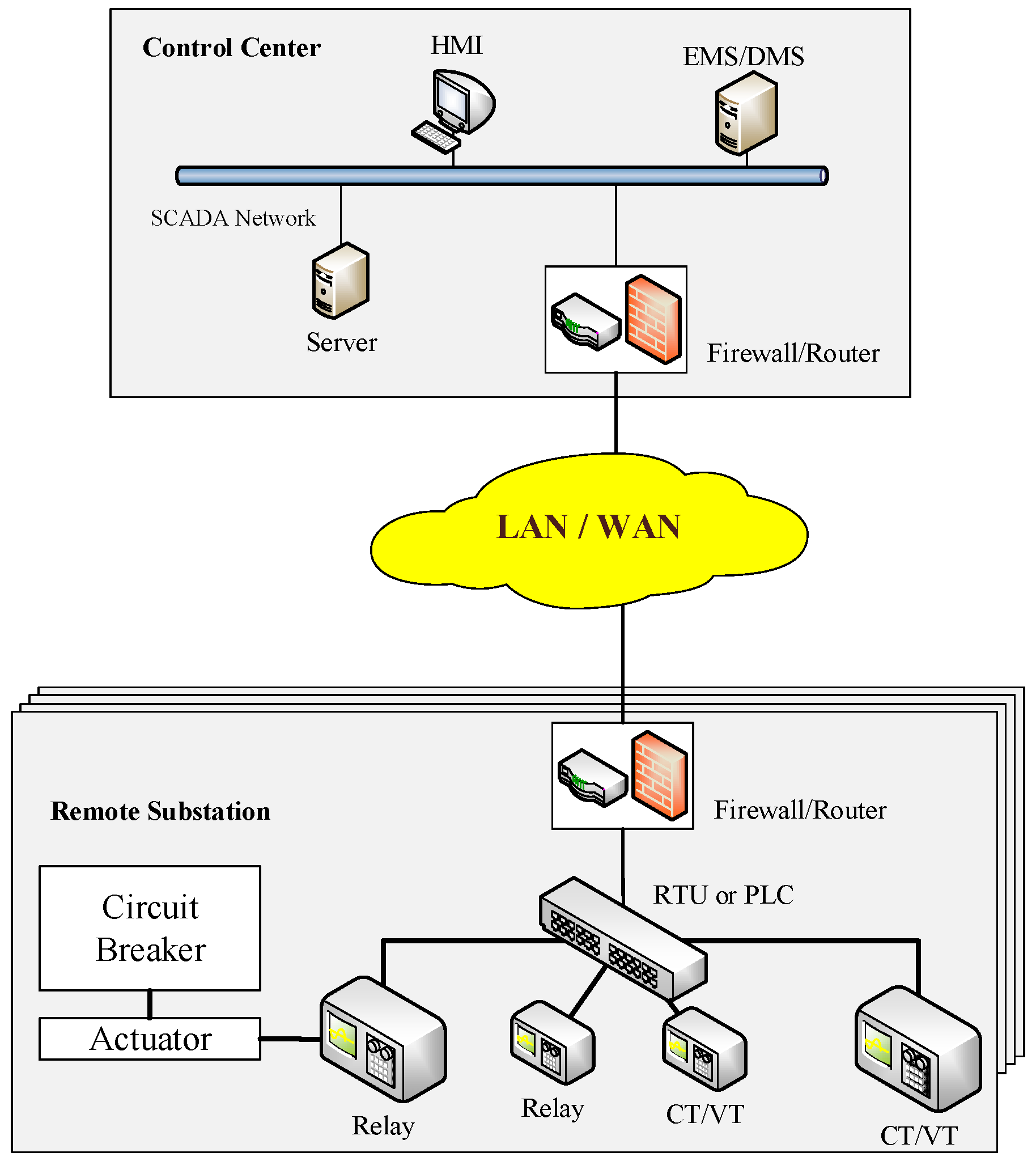
Figure 1 shows the major parts of a SCADA system: (1) sensors and control devices; (2) the digital communication system; (3) human machine interface (HMI); and (4) software (e.g., EMS/DMS). In the power industry, SCADA systems are used for collecting measurements by current transformers (CTs) and voltage transformers (VTs) and sending control commands to switching devices (e.g., circuit breakers).
The set of SCADA data at remote sites is sent to the control center via WAN (e.g., radio, satellite and Internet). As a result, the data will be delivered through the LAN in a control center. Devices connected to the LAN in a control center can access the data. In remote sites, sensors (e.g., current and voltage sensors) are connected to PLCs or RTUs via copper wires directly. If the substation uses an RTU or PLC as a gateway, there is no LAN at remote sites. Thus, the SCADA network indicates that the LAN is utilized for passing SCADA data. Remote terminal units (RTUs) and programmable logic controllers (PLCs) serve as a gateway to provide the connection between electronic devices at remote sites and an IP-based SCADA system. Although RTU and PLC have overlapping functions on remote control and monitoring, RTUs are usually deployed for wide geographic telemetry, whereas PLCs are used for local area control [
5].
EMS and DMS are the software systems in control centers at the transmission and distribution level, respectively. Both of them are used to perform the monitoring, control and analysis functions in a power system. EMS provides functionalities, such as: (1) contingency analysis; (2) state estimation; and (3) optimal power flow. The primary functionalities of DMS include: (1) acquiring customer data (e.g., power consumption and personal data) through smart meters and/or SCADA (only measurements); and (2) outage management.
Cyber vulnerabilities that exist in the SCADA systems are discussed in [
6]. Through remote access points of a communication system, attackers may be able to disrupt communications, monitor system status, access critical data (e.g., operating plan, the topology of installed protection systems, passwords and measurement records), inject malicious control commands and inject falsified data into a control center. These actions can mislead system operators into taking inappropriate operations. Specific vulnerabilities in SCADA networks and EMS have been reported in [
7,
8]. Utilities should conduct vulnerability assessments regularly for securing their system. Specific approaches to the identification of vulnerabilities are reported in [
9,
10]. To assess the vulnerability in communication systems, an integrated risk assessment method is proposed for both physical and cyber systems [
11]. Every security event is assigned with a probability value. A vulnerability index is calculated based on the cause-effect relationship between a cyber intrusion event and the power grid. It is used to quantify the degree of cyber security risk in an SCADA system. The probability of each security event affects the value of the vulnerability index. Another study of the vulnerability is performed by utilizing detailed models of the SCADA system [
12]. Vulnerabilities are investigated at three levels: (1) systems; (2) scenarios; and (3) access points. In this research, the physical and cyber system models, as well as the model of intrusion behavior (i.e., scenario level) and access points (e.g., firewall, virtual private network, dial-up connection, wireless and other remote logon applications) are included. The result of the evaluation is the total loss of load that can be caused by a cyber attack in a power system and the power system’s proximity to a collapse point, leading to a major outage.
2.2. PMU
The data scanning rate of an EMS is 2 to 5 s with unsynchronized measurement signals. Voltage angles of each bus cannot be measured directly by the current SCADA systems; they are obtained by power flow calculation or state estimation. To enable direct measurements of the voltage angles, the first set of experimental PMUs was developed at Virginia Tech in 1988, and the commercial PMU products were initially built by Macrodyne in 1992. PMUs have an extremely high sampling rate from 30 to 120 samples per second [
13]. With the high accuracy of the timing pulse (less than one microsecond) of the global positioning system (GPS), the data can be aligned on each time frame. The large amount of synchronized data can be used to improve the on-line monitoring of power system dynamics, including voltage stability, small signal ability and transient stability [
14,
15,
16].
A phasor data concentrator (PDC) serves as a gateway in the phasor network. Local PDCs are installed in substations for collecting the PMU information and forwarding the data to the PDC in a control center. The data are used for further static and dynamic analysis. Similar to cyber vulnerabilities in SCADA systems, attackers may hack into the phasor network to monitor or inject false data. In addition, PMUs use the GPS signal from satellites. Attackers may create abnormal operating conditions on a power grid by jamming or spoofing GPS signals [
17,
18].
2.3. Substation Automation System
Traditional electronic devices at substations have been upgraded to IEDs, such as protective IEDs, merging units (MUs) and intelligent controllers. In addition to the functions of conventional electronic devices (e.g., protective relays, CTs and VTs), IEDs provide the digital communication with a remote control center. The Working Group (WG) 10 of the International Electrotechnical Commission (IEC) Technical Committee (TC) 57 proposed the concept of SASs. As a result, utilities gradually adopted the IEC 61850 standard for the design of SASs [
19]. The characteristics of IEC 61850 are summarized:
- (1)
Reducing the cost of installation and engineering:
IEDs are connected to a local area network (LAN) in a substation via Ethernet-based communication. Hence, copper cables are replaced by communication lines (e.g., optical fibers and Ethernet cables) that offer higher transmission rates. All data and control commands can be transmitted using a single communication line, leading to a reduced cost.
- (2)
Enhancing interoperability of IEDs:
All IEC 61850-based devices (e.g., IEDs) are able to import/export the substation configuration language (SCL) file, which contains device information from/to a server via the ICT network. With the auto-configured feature, IEDs of different vendors can be adopted in the same substation without a compatibility issue.
- (3)
Minimizing the impact of a change in topology:
Substation engineers can connect/disconnect IEDs into the existing SAS. Through the ICT network, engineers can send the SCL files to all on-line IEDs for reconfiguration at the same time.
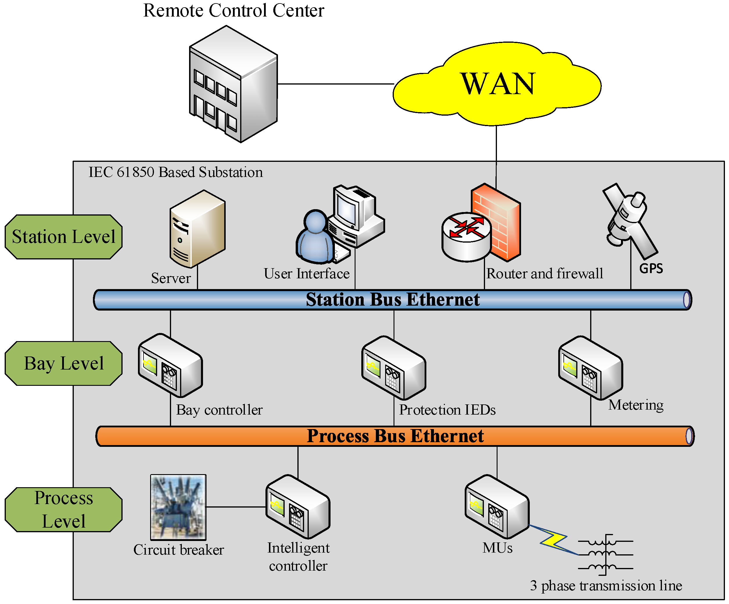
Since most power substations are unmanned, operators use remote control technologies to access the substation communication network (SCN). The architecture of an SCN is illustrated in
Figure 2. Once an attacker explores approaches (e.g., cracking the password) to access a SCN, (s)he gains access to the critical data (e.g., system topology and operating plans, measurements, maintenance records and the status of circuit breakers) and is able to send control commands (e.g., opening circuit breakers). Attackers can access multiple substations at the same time if the communication system is vulnerable. The worst case is that an attacker triggers a sequence of cascading events on a power system causing a wide area blackout.
For the purpose of a secure SAS network, several guidelines have been published. The North American Electric Reliability Corporation (NERC) developed critical infrastructure protection (CIP) standards CIP-002 through CIP-009 for “providing a cyber security framework for the identification and protection of critical cyber assets to support reliable operation of the bulk electric system” [
20]. NISTIR 7628, guidelines for smart grid cyber security, was proposed by NIST [
4,
21]. In addition, the Energy Sector Control Systems Working Group (ESCSWG) published the document, “Roadmap to Achieve Energy Delivery System Cyber Security” for improving the cyber security of energy delivery systems [
22].
2.4. AMI
An advanced metering system is a customer-side technology for smart grids. Smart meters lead to a new relationship between power consumers and providers. Conventional meters (i.e., mechanical meters and digital meters) are used to record the power usage for billing purposes. Smart meters are able to record both energy flows in and out of a house. With smart meters, consumers can also become producers by installing roof-top solar panels and/or small wind generators. Moreover, electric vehicles can be an energy resource by restoring energy when electricity prices are low and injecting power back to the grid when electricity prices go up. The digital communication system opens the door to make load demand more flexible.
A smart meter has several components, i.e., current and voltage sensors, digital communication module, data storage unit, microprocessor and RAM. Smart meters are installed on the customer side. Thus, the device can be more vulnerable than other utility side facilities in a power grid. Since smart meters record detailed usage information of the clients, attackers may be able to access users’ private information in addition to stealing electricity [
23,
24,
25].
A smart meter also serves as a controller and a router in a home area network (HAN). Based on the vision of the Internet of Things (IoT), home appliances can be connected to the Internet and controlled by smart phones via the Internet. Smart meters are ideal devices as a controller because they support wireless communication [
26]. In a wireless communication environment, appliances can be added/removed in a HAN without wiring and configuring issues. Currently, most smart meters are designed to use the ZigBee communication protocol defined in the IEEE 802.15.4 standard [
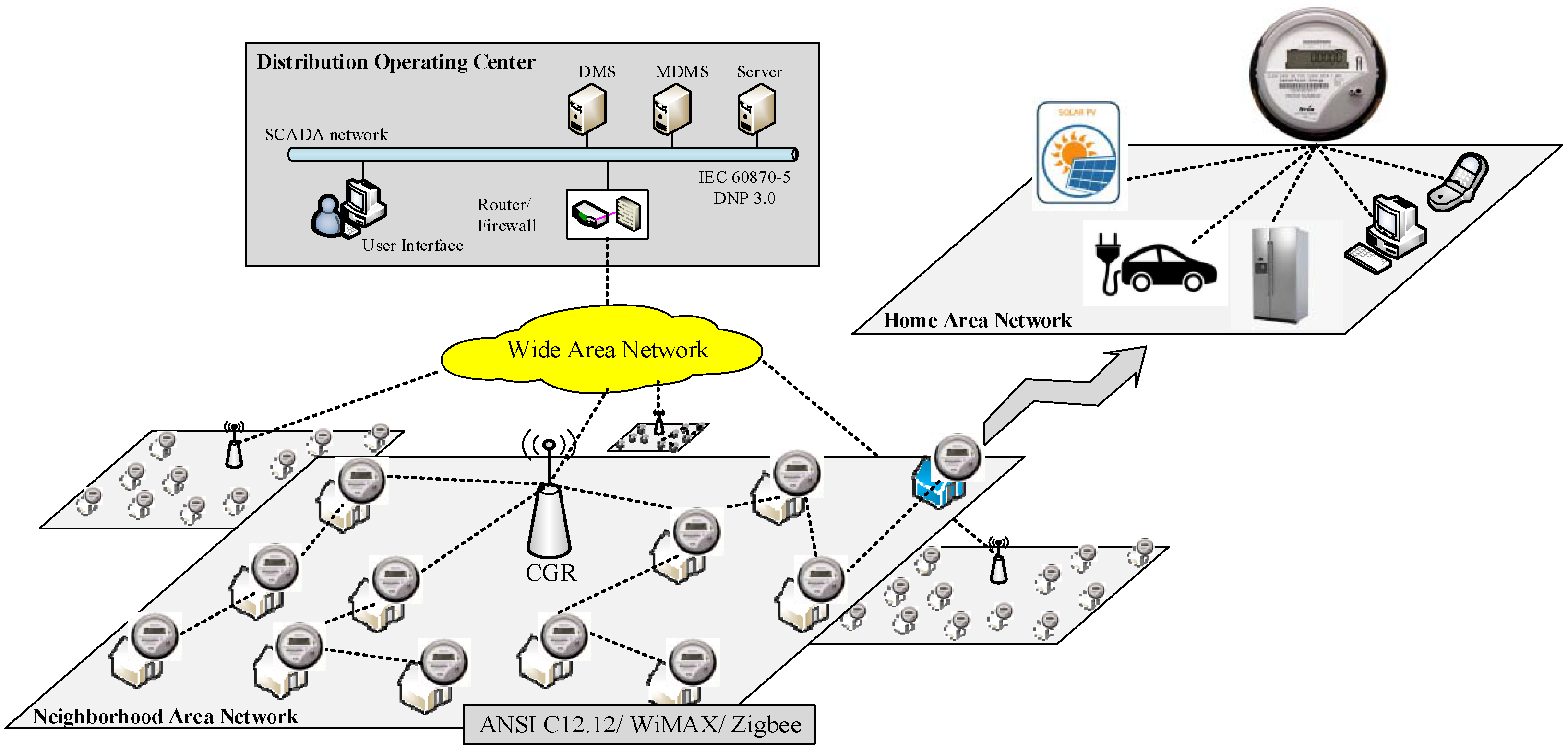
27]. ZigBee has a communication distance limit because the technology is designed for electronic devices with low power consumption. Unlike Wi-Fi technology using a star topology, ZigBee support devices are connected in a meshed network where data can be exchanged between end-devices. Therefore, the transmission distance can be extended by hopping among devices in the same LAN. The communication structure of an AMI network is shown in
Figure 3. A connected grid router (CGR) collects meter data in a neighborhood. Several communication links pass the data from end points to the CGR. Commands from a control center propagate in reserve direction from the CGR to the control target. If any of the meters in the middle of a linkage go off-line, the link topology will be automatically reconfigured by a preset plan. However, computer viruses or malicious application programs can also be spread in an AMI network in a short time, since meters can communicate with each other. Thus, many cyber security studies on AMI focus on the security of communication protocols and secured communication structures [
28,
29,
30]. NIST and user groups, such as the Open Smart Grid, have produced reports and enacted requirements to ensure that manufacturers and policy makers incorporate cyber security from the beginning of the development process. These documents range from risk assessment [
31,
32] to security requirements [
4].
2.5. Overview
Except for the SCADA system, PMU, SAS and AMI belong to the smart grid. “Smart” means that the data can be sent/received through the digital communication system. In the SCADA system, measurements collected by gateways (e.g., PLCs or RTUs) are provided by sensors and transmitted via copper wires. Although the digital communication system is utilized by PLCs or RTUs for transmitting data to the control center, the communication between sensors and gateways remains traditional. Therefore, SCADA does not belong to smart grid technologies.
Communication protocols define the digital data formats and rules for telecommunication. With respect to different requirements (e.g., latency, security and packet size) of communication systems, different communication protocols are utilized. The latest version of the communication protocols in power systems is listed in
Table 1. In addition, vulnerability assessment approaches of the subsystems (i.e., SCADA, PMU, SAS and AMI) of power grids are provided. The information of vulnerability studies has been tabulated in
Table 2.
3. Cyber Intrusion Protection Systems
As a packet filter, the firewall serves as the front-line defense for a protection system. Packets that fulfil the user-defined rules can pass firewalls. Anomaly events (e.g., unknown IP connection, IP scanning and port scanning) are recorded in a log file. However, firewalls only examine the lower layer communication information (i.e., network layer). Therefore, malicious code cannot be detected in the higher layer of the communication structure (i.e., application layer). Thus, except for firewalls, various types of IDSs and ADSs have been proposed to capture abnormal behaviors towards the communication system.
IDSs are used to detect intrusion behaviors in power systems. After receiving an intrusion alarm from IDSs, operators can take a control strategy to mitigate the impact of cyber attacks. In addition to the functions of IDSs, intrusion detection and prevention systems (IDPSs) can apply a control strategy to the cyber attack with an appropriate mitigation method directly. Therefore, IDPSs respond to cyber attacks (before/after) faster than IDSs. The impact on a power system is reduced further.
3.1. Types of IDSs
A smart grid is an integration of both physical and cyber systems. The physical system consists of power generation units, substations and transmission and distribution systems, while the cyber system represents the digital communication system (e.g., ICT network) and SCADA system. The principles behind the design of IDSs for cyber and physical systems are very different.
3.1.1. Network-Based IDSs
A network-based IDS (NIDS) monitors the network traffic in a LAN. Through a physical network interface card connected to the LAN, an NIDS gains access to all network flows in a network segment. NIDS checks for anomalies by inspecting the contents and header information of all packets passing through the network segment. Each communication protocol has a uniquely-defined format and structure of network packets. As a result, anomalies can be recognized by comparing predefined rules with abnormal packets [
33,
34].
3.1.2. Host-Based IDSs
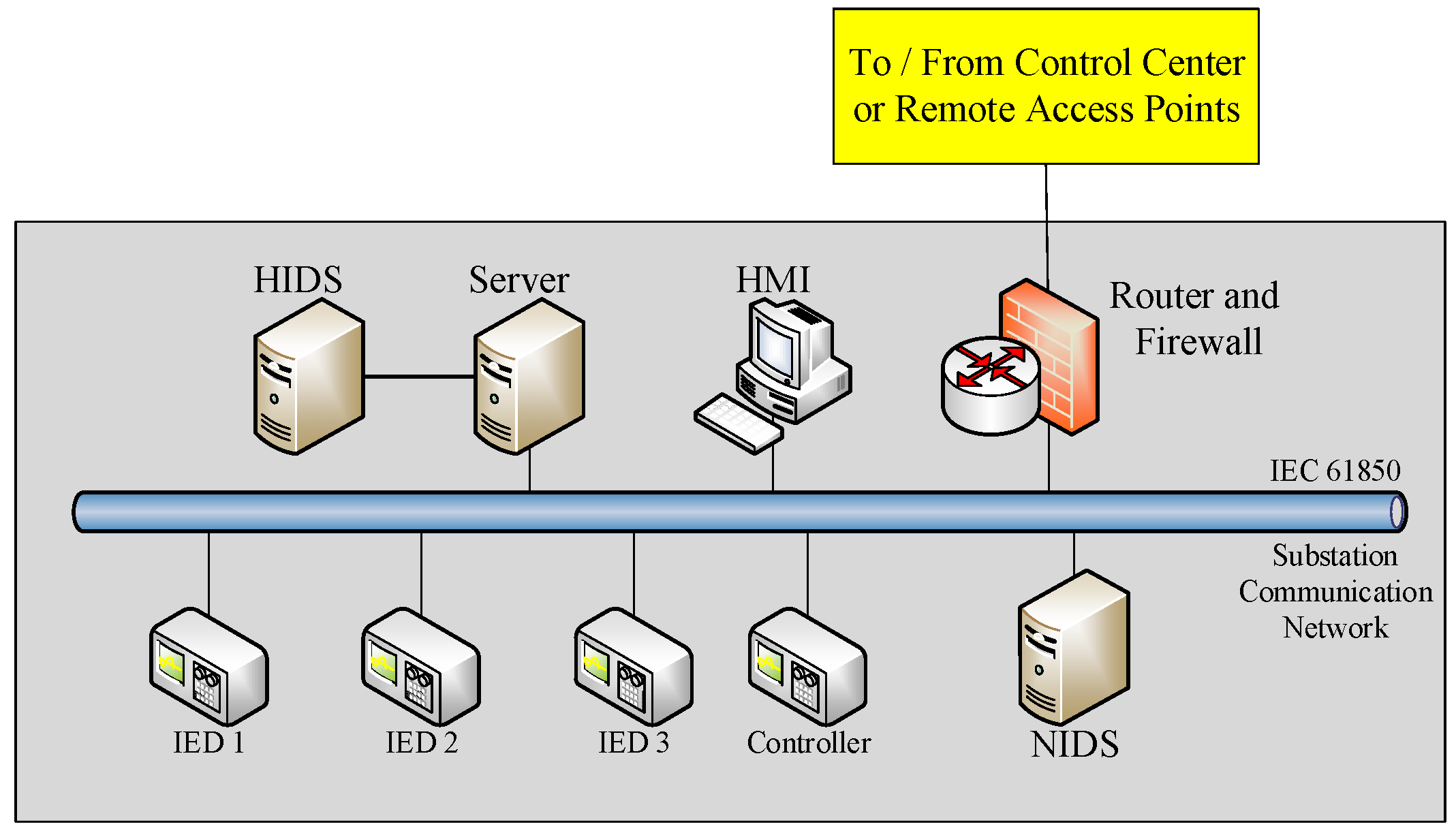
A host-based IDS (HIDS) is installed in one or more data servers individually. The primary task of an HIDS is to identify anomalies among measurements and the status of physical devices. A HIDS also has a set of user-defined rules that describe the normal behavior among the devices. For example, if a circuit breaker is opened without a detected fault signal, the HIDS will consider this event as an anomaly. Thus, a HIDS utilizes log files recorded by physical equipment, such as IEDs, PMUs and firewalls [
35]. The architecture of NIDS and HIDS in a substation is shown in
Figure 4.
3.2. Detection Systems and Mitigation Techniques in Smart Grids
3.2.1. Detection Systems
Blacklists and whitelists are two typical detection approaches. A comparison is shown in
Table 3. Anti-virus applications for personal computers are good examples that use the blacklist. A virus can be recognized by comparing its signature with records in a database. If the signature is matched, the virus will be quarantined or deleted. In contrast, an example of the whitelist detection system is the access to a control system, which utilizes a database to record the information of authorized users. Database rules must be updated frequently for both whitelist and blacklist detection systems. Otherwise, the latest anomalies would not be recognized by the detection system. Similarly, the whitelist detection system needs to be updated so that it allows the newly-authenticated operations to be conducted.
Intrusion detection technologies have been explored in the ICT environment. However, attack vectors, vulnerability, availability requirements and interactions between physical and cyber domains are new challenges to power systems. Several studies of IDSs for the power grid have been reported. A list of IDSs is shown in
Table 4.
Most IDSs are either host-based or network-based. However, a hybrid IDS has a higher performance in a CPS. For this purpose, an integrated ADS for substation cyber security is proposed [
45]. The host-based anomaly detection inspects temporal anomalies in the substation facilities. Meanwhile, multicast messages (e.g., GOOSE and SMV) are monitored by the network-based anomaly detection. Cyber attacks can be identified by correlating the information from both parts of anomaly detection systems (ADSs). In
Section 4 of this paper, a test example of the integrated ADS in the Smart City Testbed (SCT) is presented.
3.2.2. Mitigation Techniques
The primary task of mitigation actions is to ensure the reliability and stability of a power system. Mitigation actions are activated as soon as IDSs or IDPSs report an attack event. In general, mitigation methods include two parts, cyber and physical systems. For the cyber system, the mitigation techniques are aimed at verifying the legitimacy of on-line users and network packets. For the physical system, the mitigation control strategies are applied to maintain the stability of power systems. If attacks affect the stability of power systems, control strategies must be applied. A mitigation framework and control strategies of generators are proposed in [
46] to maintain system stability with respect to switching attacks. In the study of [
47], both cyber and physical mitigation steps are included. Unknown on-line users will either be suspended or have very limited manipulation privileges. Another mitigation technique reported in [
48] is used against the man-in-the-middle (MITM) attack. DNP 3.0 is a common communication protocol for SCADA systems. By utilizing a packet retransmission strategy [
49], the authors suggested that the MITM can be prevented.
3.3. Detection Systems of AMI Network
In [
50], it is reported that the number of installed smart meters in the U.S. has reached 65 million by 2015. The deployment of smart meters is a continuing trend in the power industry. A cyber security issue for smart meters is energy theft, e.g., an attacker modifies the values of energy consumption readings. Several detection systems have been developed against energy theft [
51,
52,
53,
54]. Through monitoring load profiles, detection systems are able to recognize anomalies, such as the drastic change of power usage at a specific time instant and unusual power usage patterns. Another purpose of detection systems [
55,
56,
57] is to secure the communication and avoid information leakage. Authorization, authentication and encryption technologies are applied to enhance the security of private information. Most research on the AMI cyber security is focused on: (1) energy theft; and (2) information security (i.e., power usage and false data injection). As smart meters have limited computational capability, detection systems should be designed with a low computational burden [
55]. The practical implementation of smart meters with the capability of IDSs is still limited.
4. CPS Testbeds
Researchers investigate potential cyber vulnerabilities in the smart grid. In doing so, it is risky to perform cyber security studies on a real power system. Therefore, a real-time CPS testbed serves as a feasible alternative since it can capture interactions among cyber-control-physical subsystems. A CPS testbed has several advantages: (1) power system simulation tools (e.g., Real-Time Digital Simulator (RTDS), DIgSILENT, PowerWorld, TSAT and PSS®E) can simulate the response of a large-scale power system with a reasonable level of accuracy; (2) a testbed can be focused on a specific security study area (e.g., distribution system, transmission system, SCADA system and AMI network); and (3) a testbed can be extended through connecting multiple testbeds via communications (e.g., Internet and LAN). Testbed-based research is important for areas such as: (1) vulnerability assessment; (2) impact analysis; and (3) attack-defense evaluation and validation.
4.1. National Level Testbed
The DOE Office of Electricity Delivery and Energy Reliability (OE) created a testbed program in 2008. A National SCADA Test Bed (NSTB) has been established by collaboration among National Labs (i.e., Argonne, Idaho, Lawrence, Berkeley, Los Alamos, Oak Ridge, Pacific Northwest and Sandia) for identifying and reducing existing cyber vulnerabilities in energy sectors (i.e., electric, oil and gas) and testing new and existing electronic devices that are used in energy industries [
58,
59,
60]. To meet the objectives, the NSTB program invests in R&D for next-generation control systems, vulnerability assessment and risk analysis to enhance cyber security in energy systems, as well as physical grid components, including generation units and transmission systems to build a realistic testing environment. However, the substantial cost of physical infrastructures places limits on the development of these testbeds.
4.2. Testbed at Research Institutes
The cost of a national-level testbed is high. Several research centers have developed a smaller scale of CPS testbeds for different CPS security studies. A CPS testbed, Virtual Power System Testbed (VPST) [
61], at the University of Illinois has the ability to simulate both cyber and physical systems by using a network integration tool based on the Illinois-developed Real-Time Immersive Network Simulation Environment (RINSE) and a power system simulator (i.e., PowerWorld and RTDS). Except for performing cyber-physical security studies, this testbed also shows the interconnectivity between multiple testbeds. The framework of inter-testbed connector (ITC) was proposed for reducing the complexity of the testbed configuration.
The Cyber Security testbed at University College Dublin (UCD) is intended for the cyber security study of the SCADA system. The testbed consists of four parts: (1) a commercial EMS is used in the SCADA system network; (2) IEC 61850 communication formed the SCN in simulated substations; (3) a power system simulation tool (i.e., DIgSILENT) is used to simulate a power system; and (4) the Object Linking and Embedding for Process Control (OPC) communication protocol bridges the physical and cyber domains [
62].
With the effort of previous research project (i.e., Internet-Scale Event and Attack Generation Environment (ISEAGE)) at Iowa State University (ISU) [
63], the PowerCyber Security testbed is able to perform the wide area network emulation and advanced attack simulation. Both hardware-based (RTDS) and software-based (DIgSILENT) power system simulation tools support the real-time and off-line system simulation. With respect to advanced virtualization technologies, the cost of development can be reduced and the scalability of testbeds can be addressed.
A number of CPS testbeds have been developed for the study of cyber security issues of power systems. However, most of them are not public. Researchers from the University of Southern California and University of California, Berkeley, emphasize the existence of a significant gap between defense mechanisms and attack techniques. In order to accelerate the development of cyber protection systems, a plan is proposed to involve more researchers to work together. The defense technology experimental research (DETER) project [
64,
65,
66] started in March 2004. It provides a public platform that allows researchers to share data, tools, configurations of the testbed and applications. In addition, it helps researchers start new projects with the results of completed experiments and test cases.
4.3. SCT at Washington State University
4.3.1. Configuration of the SCT
A comprehensive testbed for the simulation of cyber-power systems has been developed at Washington State University [
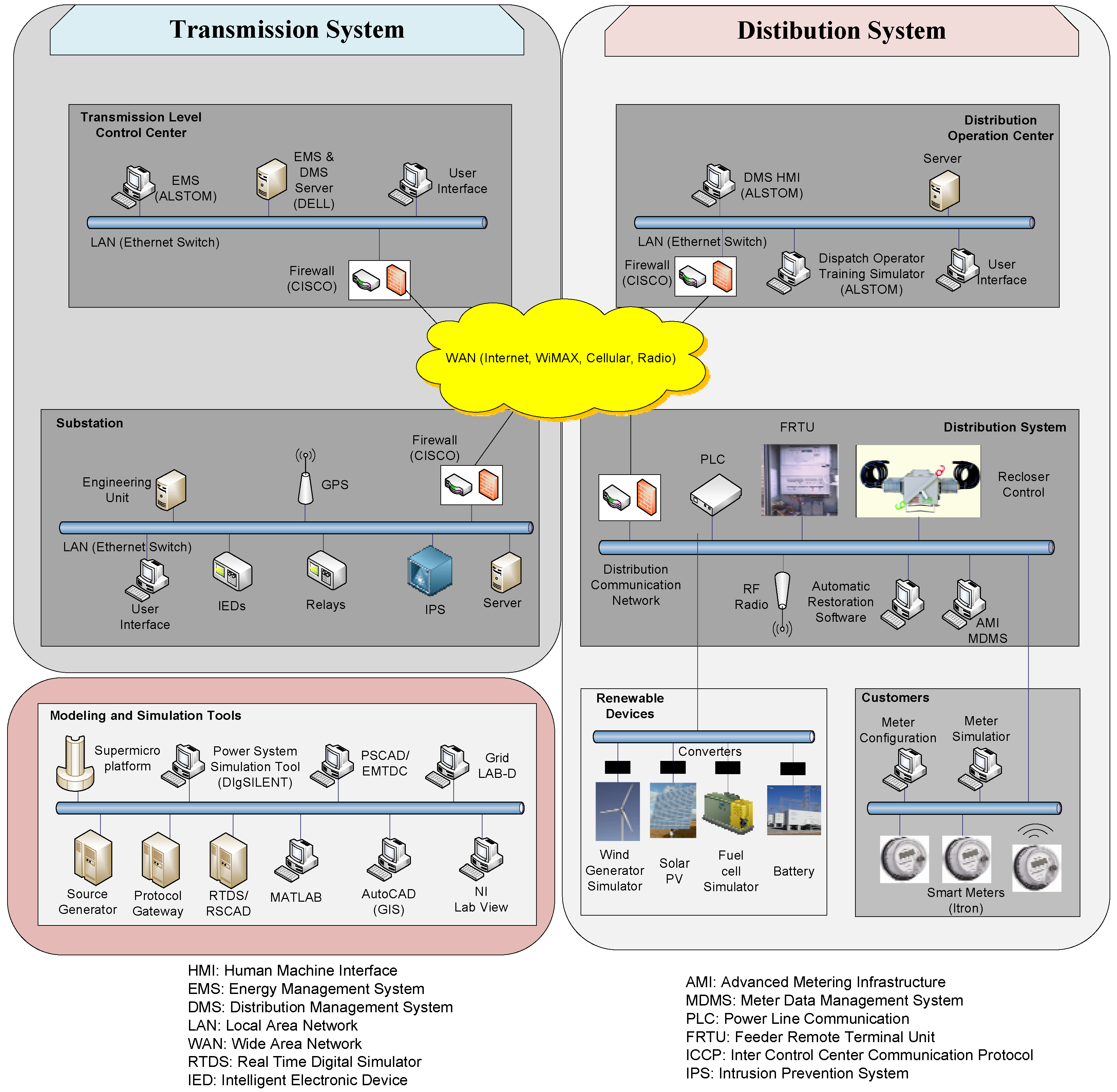
67]. The architecture of SCT is shown in
Figure 5. Unlike other testbeds that focus on some subsystems, SCT is a hardware-in-the-loop testbed that covers from the control center level all the way to smart meters at the customer level. The transmission system, distribution system, DER and AMI are also included. The physical system components of the SCT include protective IEDs, feeder protection relays, smart meters and data collectors. DNP 3.0, IEC 61850, ANSI C12.19 and IEEE C37.118 formed the communication network protocols. EMS and DMS are available to simulate the operations at a transmission control center and a distribution operation center, respectively. The functions of EMS (such as contingency analysis, state estimation and optimal power flow) are used to study the impact of cyber intrusion on a power system. The DMS can import the real-time customer data (e.g., power usage) collected by smart meters installed on the WSU campus. Other smart meters are installed in the lab for research purpose. These meters will be used to study cyber intrusions into the AMI network with the meter data management system. As several power system physical devices are deployed, the SCT is a realistic model of the real-world environment. Compared to the national level testbed, SCT uses software models for transmission lines, circuit breakers, substations and generators. The characteristics of the SCT includes: (1) a realistic software-hardware simulation environment; (2) several communication and control devices are implemented; (3) different combinations of physical configuration can be tested for identifying cyber security leakages; and (4) the impact of cyber attacks on the entire power system can be investigated from transmission, distribution to the customer level.
4.3.2. Test Case
A cyber attack scenario is demonstrated on the SCT using the IEEE 39-bus system. The integrated ADS proposed in [
45] is applied to and validated by the same scenario. For the cyber attack, it is assumed that attackers have full knowledge to access the communication systems in multiple substations. Attackers are able to send modified GOOSE packets to trip all circuit breakers on targeted substations.
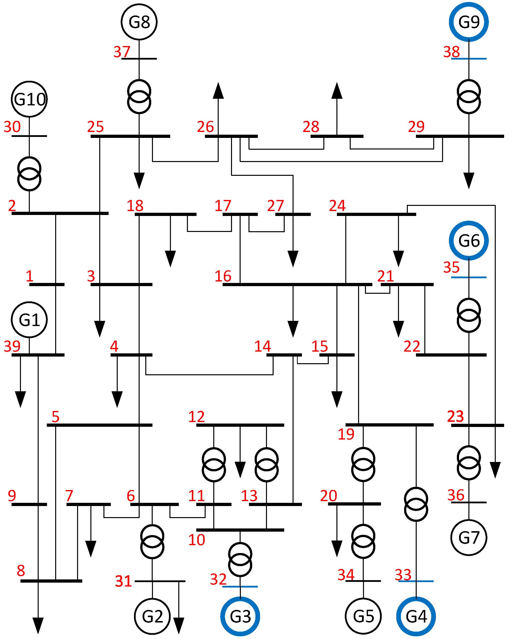
In the first scenario, the targets are selected as Substations 38, 32, 35 and 33. Note that the most valuable targets are the buses connected to generators directly. The attack starts at t = 3 s. One substation is compromised every 3 s. The last target (i.e., Substation 33) is compromised at t = 12 s. The attack sequence and the target information are listed in
Table 5. During the attack, over-current relays report that circuit breakers are opened without sensing an over-current condition. In
Figure 6, the targeted substations are depicted in the one-line diagram of the IEEE 39-bus system. After four generators connected to the targeted substations are disconnected, a cascading sequence of events is triggered, since the power system loses a significant portion of generation capability. A wide area outage occurs at the last stage. The load and generation levels of the IEEE 39-bus system are shown in
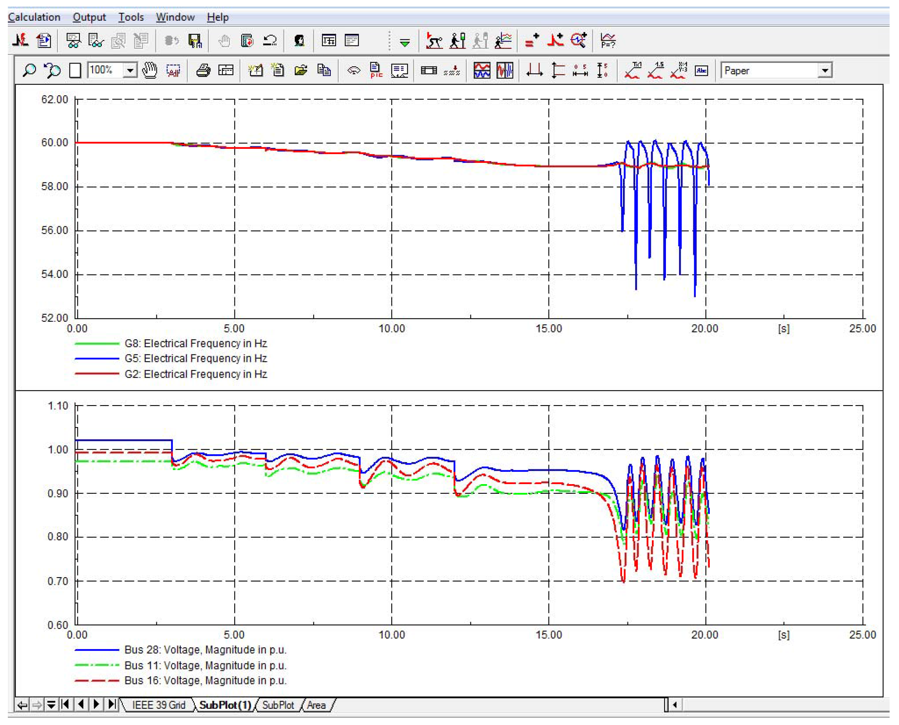
Table 6. Generators cannot provide sufficient MW power to serve the load after the cyber attack. Dynamic simulation results of the cyber attack are shown in
Figure 7.
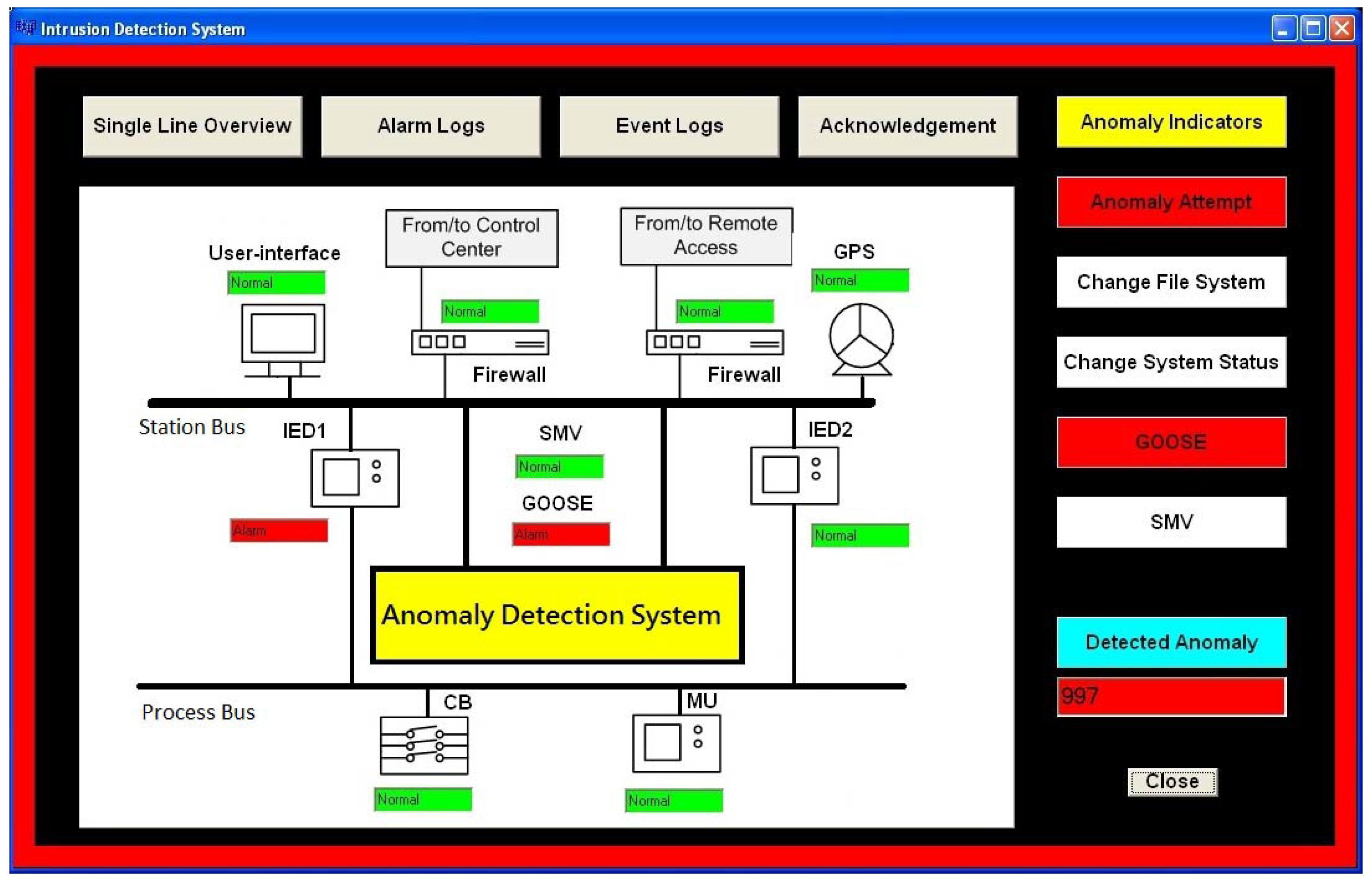
In the second scenario, the proposed integrated ADS [
45] is deployed with the same cyber attack scenario. The HMI of ADS that shows the number of detected anomaly packets is shown in
Figure 8. Note that a small number of modified packets is not detected due to the extremely high packet rate. In the meantime, protection IEDs await the confirmation signal from ADS when falsified packets are received. Since an abnormal behavior has been detected, ADS sends a signal to lockout the circuit breaker. Thus, all circuit breakers remain closed during the cyber attack. The proposed ADS has been validated by the SCT.
5. Conclusions
The extensive deployment of ICT systems transforms traditional power grids into smart grids. The increasing connectivity also creates cyber security vulnerabilities. As a result, CPS security has become a critical issue for the smart grid. In this paper, the state-of-the-art of vulnerability assessment for CPSs is conducted with a focus on the impact of cyber intrusion. New vulnerabilities may be derived from the system reconfiguration and/or upgrade. Therefore, vulnerability assessment should be conducted on a regular basis, particularly after a system reconfiguration. As an alternative to testing on the actual cyber-power system, a testbed provides a substitute for the impact analysis of cyber attacks. A testbed should have the capability to mimic the behaviors of real systems. Reliable and accurate simulation tools (software and hardware) of the power and communication systems are needed to provide a realistic cyber-power system environment.
Various types of ADSs and IDSs have been proposed to monitor the cyber-power system behaviors. The design of detection systems should meet the requirements of power systems, such as transmission delay and system performance. An over-designed detection system that bears a high computational burden may reduce the performance of both power system and detection system.
In December 2015, cyber attackers compromised multiple substations likely by utilizing the malware “BlackEnergy” installed in computers of the control center. During the attack, attackers launched the flooding attack on the telephone system and, as a result, customers were not able to report the event to the utility. This fact allowed attackers to compromise a larger number of substations. The falsified SCADA dataset was injected into the control center. Therefore, the operators were not aware that the system was de-energized. Due to this cyber attack, over 80,000 customers experienced power outage. This incident is a cyber attack that caused a direct impact on a power system. IDSs and IDPSs are used to analyze abnormal events in both cyber and physical systems. Even if attackers pass the identity check, alarms will be triggered once abnormal behaviors are detected in the physical system. It is shown that a cyber system’s breach of the substation security can open a pathway to allow cyber attackers to access the substation communication network and impact physical systems.


