Recent technology trends in ultra-low power microcontrollers and sensors pave the way to applications requiring small amounts of power (from a few μW to a few hundreds of μW). For this purpose, ubiquitously available radio frequency (RF) sources, operating at different bands, with unknown directions of incidence and polarizations, can be exploited by rectifying antenna (rectenna) systems to provide a solution to this problem [
16,
17]. However the available amount of RF energy is low, even in highly humanized environments [
18], and typically, only a few μW of power can be provided by highly efficient rectennas. We thus imagine that these systems could be more suitable for “RF upon request” applications [
19], always exploiting the sources typically present in all humanized environments, but in correspondence with a precise demand by the user (e.g., a nearby mobile phone call). From this point of view, a fully-wearable rectenna for technology garments can find its proper application [
7,
20]. The design of such a system is a delicate issue, since there is a number of challenging aspects in RF energy harvesting to be considered, such as the spatial/temporal variability of RF sources and the frequency of operation: thus, a useful rectenna must have a highly efficient antenna, operating at different bands, with unknown direction of incidence of the incoming field, and must efficiently rectify the received RF power. When wearable devices are concerned, additional problems have to be faced: the effects of body and of topology variation (e.g., layer bending and/or shift) on the system performance must be accounted for.
Here, we describe the accurate design of a highly efficient, completely wearable tri-band rectenna, consisting of a compact multilayer structure resonating at the GSM 900, GSM 1800 and WiFi frequencies.
3.1. Design Procedure
The different design domains, firstly introduced in [
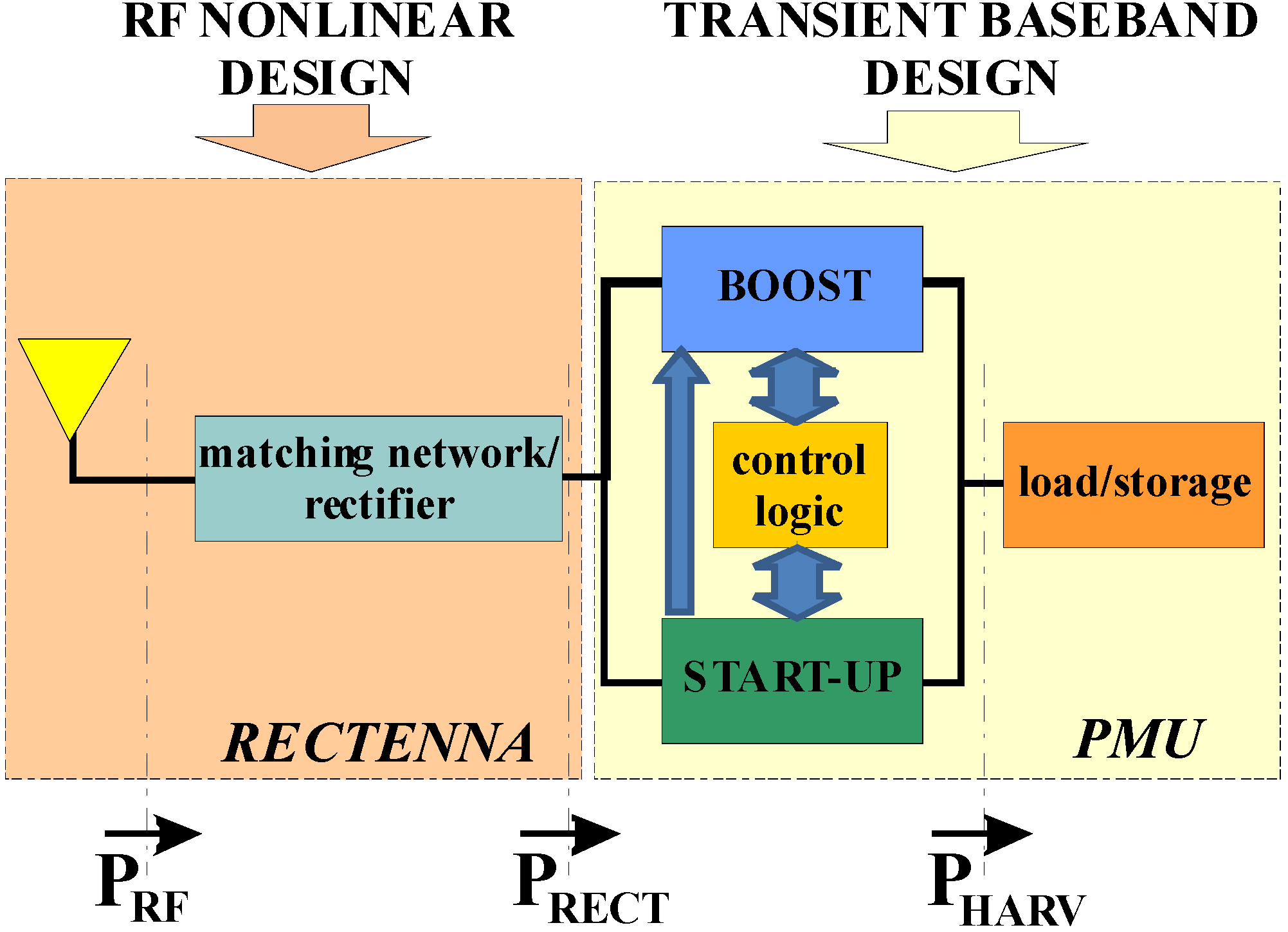
6], that should be adopted to accurately define and dimension the building blocks of a harvesting system are schematically depicted in
Figure 2. Note that in this formulation, the RF harvesting system is expected to operate whenever the RF energy is available and to store it for immediate or future usage in an efficient way, through a power management unit. Thus, the operating rates of the entire system spans from the microwave spectrum, where the RF energy is located, down to the baseband, where the DC/DC converter operates.
Figure 2.
Block diagram of the multi-domain CAD tool for rectenna design.
Figure 2.
Block diagram of the multi-domain CAD tool for rectenna design.
The key difficulty for this class of systems design is thus the ability to combine the results of the nonlinear rectenna regime, more suitable for the harmonic-balance analysis based on complex phasors, with the time-domain results needed for the correct dimensioning of the DC/DC converter. The correct combinations of these domains is of fundamental importance, to correctly account for the impedances of the different sub-blocks.
At RF, the subsystem consisting of the receiving antenna, loaded by the rectifier, and of the antenna-rectifier inter-stage network needs to be designed in a steady-state nonlinear regime by means of electromagnetic theory and software tools typical of an RF design environment, such as Harmonic Balance (HB). At this stage, the network function to be optimized is the RF-to-DC conversion efficiency, given by:
where
PAV is the available RF energy on the antenna location, while
PRECT is the rectified power at the rectenna output port, delivered to a fixed optimum load.
At baseband, the transient design of a DC-DC converter, keeping the rectifier dynamically close to the optimum load condition, is designed by transient analysis: the efficiency to be maximized in this case is a DC-to-DC efficiency, given by [
6]:
as the ratio between a fraction (
F < 1, ~90%) of the maximum energy stored in the output storage capacitor (
EHARV) during its charging time
TC.
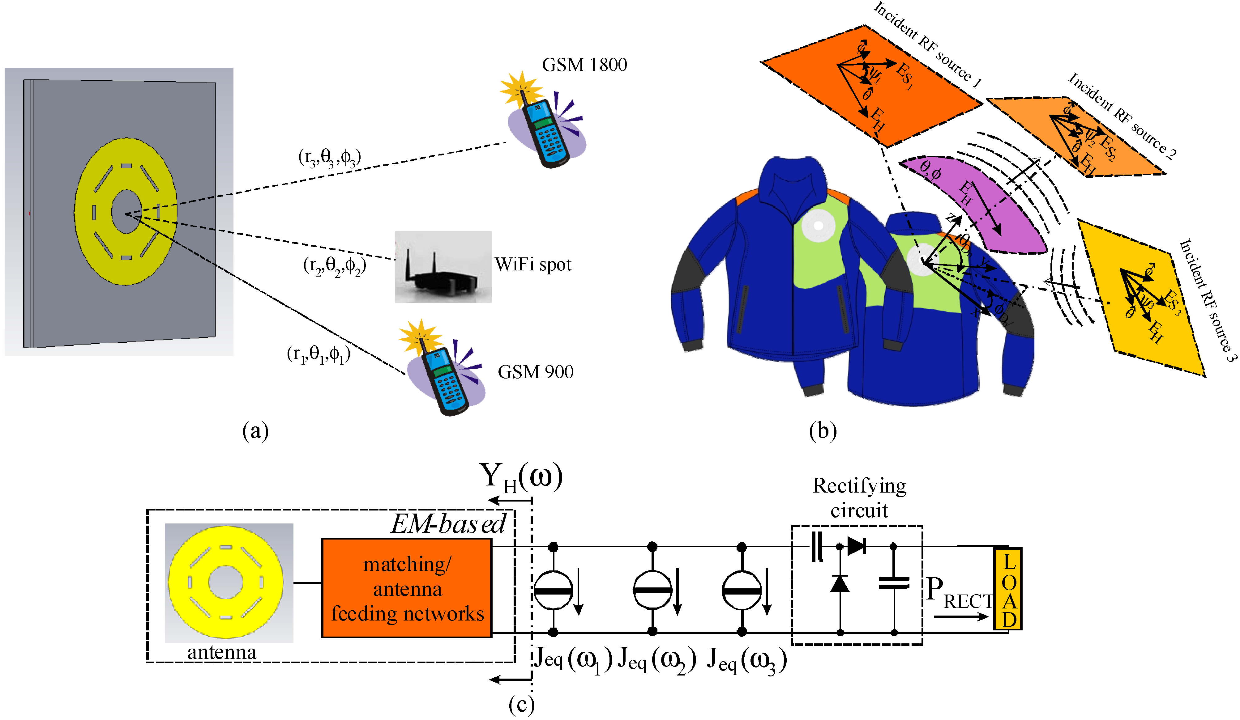
For the RF nonlinear design, we refer to the situation depicted in
Figure 3a, where the wearable rectenna is immersed in a multi-source environment. For any given RF source at an angular frequency ω
RF, we resort to EM theory [
21,
22] to effectively estimate the actual RF power available to the rectifier circuit (
PAV in Equation (1)). Under the assumption of “plane-wave approximation” for the incoming RF field (
Ei of
Figure 3b), which normally holds for conventional communication systems, the Norton equivalent current source can be easily cast in the following way [
6]:
where
EH is the far-field vector at the same RF frequency radiated by the harvesting antenna (described by the EM-based admittance
YH), when operating in the transmitting mode, powered by a voltage source of known amplitude U and internal resistance
R0. Here, r is the spatial vector defining the RF source direction of arrival in the receiver-referred spherical reference frame. It is worth noting that in the case of harvesting upon-request, the link between the RF source (e.g., mobile phone) and the receiving harvester antenna can be “unconventional”: it means that the “plane-wave approximation” may not be valid any more, due to the far-field condition violation and/or the exploitation of a link direction different from the maximum one. Furthermore, in this case, the equivalent current generator can be obtained in a rigorous way, resorting to Love’s equivalence principle [
23], according to the following formula:
where the electric and magnetic fields of both the RF source and the harvester antenna are numerically evaluated on a Ʃ plane placed in between the two antennas. Formula (4) provides correct results irrespective of the antenna orientations and transmitter-to-harvester distance and eventually takes into account the nearby objects affecting the link (such as the human body in
Figure 3b) [
6].
Note that by means of Equation (3) or Equation (4), polarization mismatch between the rectenna and the incident field is automatically and rigorously taken into account.
Figure 3.
(a) Wearable rectenna in the presence of multiple incident RF sources. (b) Electromagnetic (EM) representation of the sources as EM fields interacting with the harvesting antenna (to be used in the evaluation of Equations (3) and (4)). (c) Circuit-level equivalent description of the tri-band wearable rectenna.
By resorting to the circuit-level description of
Figure 3c, a straightforward nonlinear HB optimization can be easily performed, contemporaneously focusing on the frequency bands of interest. Moreover, the rectenna nonlinear regime due to the simultaneous incidence of multiple ambient RF sources is directly provided by a multi-tone HB analysis (as in the case to which
Figure 3c refers).
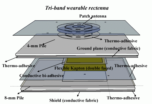
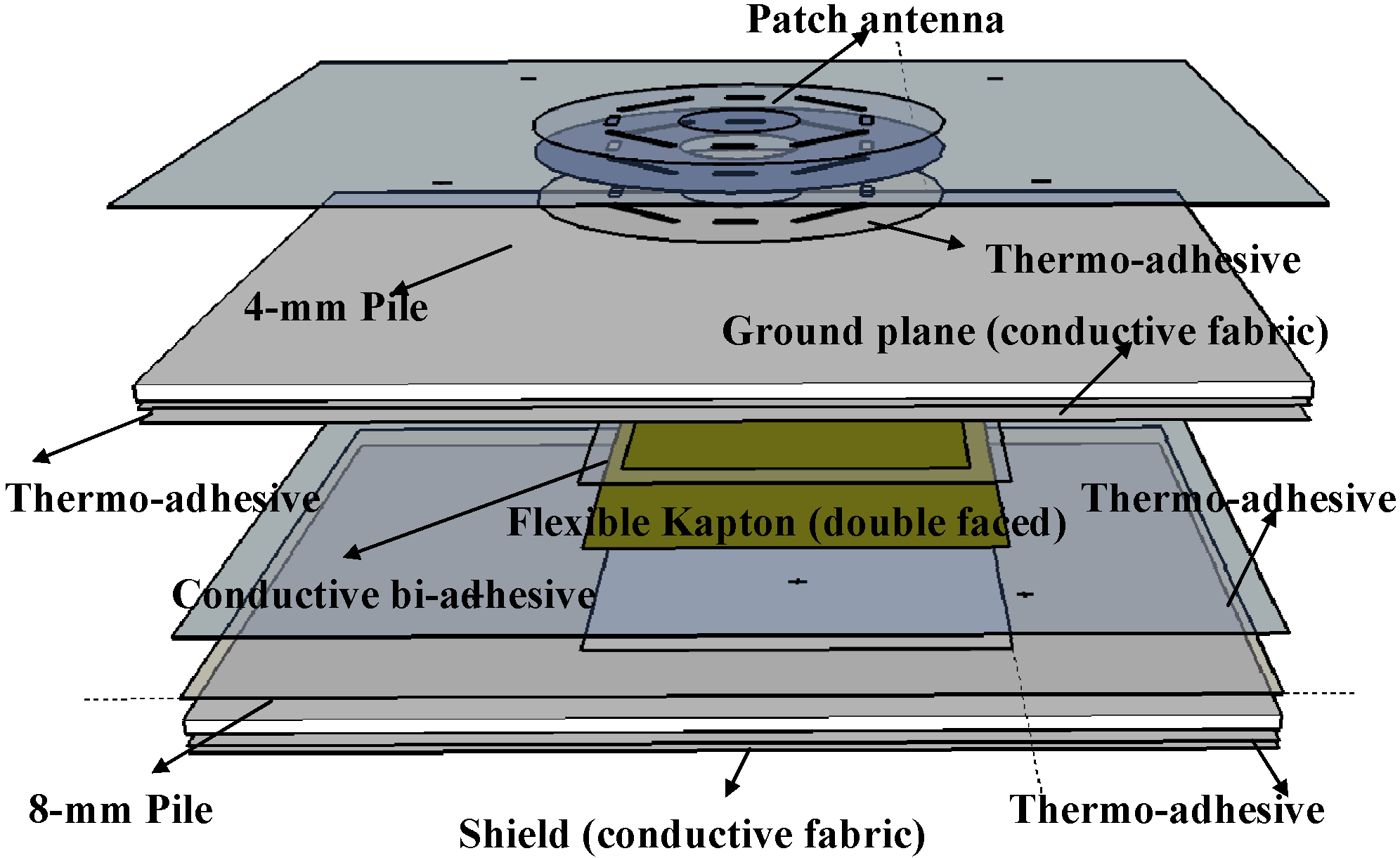
In the present design, we focus on the two GSM and WiFi frequency bands (900 MHz, 1,800 MHz and 2,450 MHz, respectively). Our architecture choice consists of a single multi-resonant antenna with a single rectifying section: this way, the unwanted EM-couplings always present in multi-antenna solutions are avoided, as well as the minimization of diode losses is achieved. The final engineered solution of the present rectenna is shown in
Figure 4, where the multi-layer adopted layout is also evident [
7].
Besides the pile substrate for the antenna, another grounded pile layer is adopted for better isolation of the human body. The only non-wearable portion is the yellow portion of
Figure 4, consisting of the 0.1 mm-thick flexible Kapton substrate (ε
r = 3.4, tanδ
ε = 0.002) under the ground plane. Its area is reduced to a minimum in order to guarantee a more comfortable wearable solution: it only contains the antenna feeding network (matching network, phase shifter and power divider) and the rectifier circuit.
Figure 4.
Stack-up of the proposed tri-band wearable rectenna.
Figure 4.
Stack-up of the proposed tri-band wearable rectenna.
The use of a single tri-band antenna, instead of a broadband one, represents the best choice in the case of low available power budgets, since the resonant behavior at each frequency is a synonym of high antenna efficiency, a fundamental requisite for the maximization of P
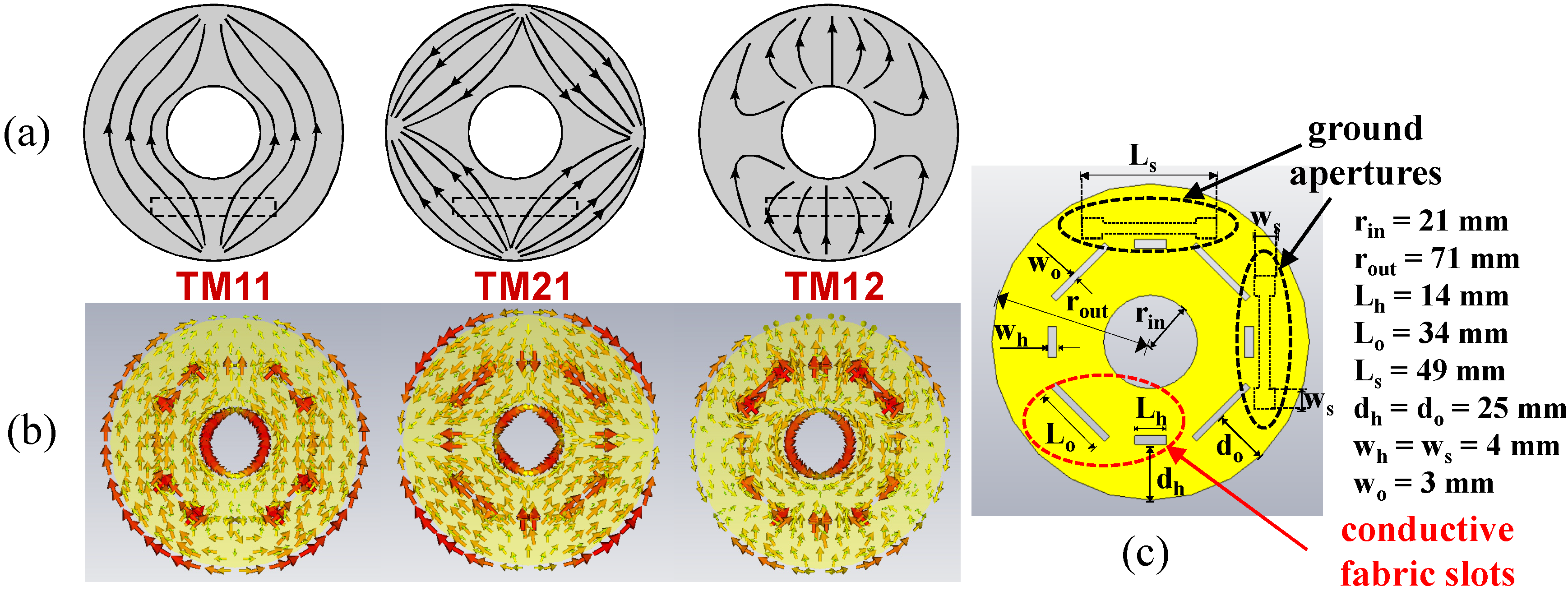
RF. In this case, we adopt an annular ring planar antenna for the exploitation of higher order modes, such as the TM12, having superior radiation properties [
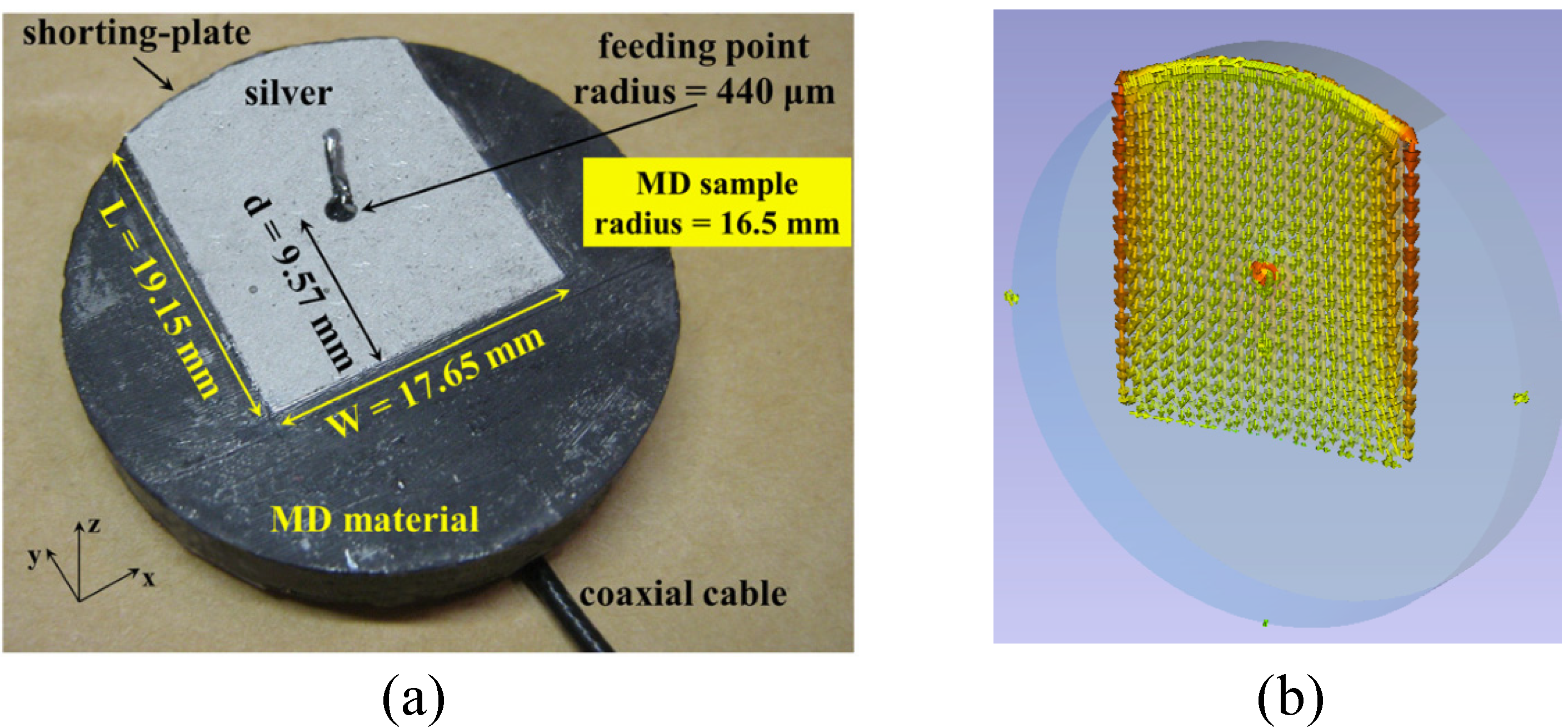
24]. In
Figure 5a, the theoretical current distribution for the three selected modes (TM11, TM21 and TM12) is reported for a generic annular patch. The main difficulty is to exactly match the three desired frequencies to the three selected modes: this is impossible by only acting on inner and outer radii dimensions; for this reason, we etch eight symmetric slots in the conductive fabric of the patch and use their dimensions as tuning parameters, thus achieving the following desired correspondence of the modes resonance frequencies: TM11 at 900 MHz, TM21 at 1,800 MHz, and TM12 at 2,450 MHz [
8].
Figure 5c shows the final slotted annular ring topology, with inner and outer radii of 21 and 71 mm, respectively, obtained after a sequence of parametric full-wave analyses for different slot area values; while in
Figure 5b, the modelled surface currents at the three resonances are reported. In spite of the slotted surface, the current distribution is quite similar to the theoretical one.
Figure 5.
(a) Theoretical and (b) simulated electric current patterns for the ring antenna selected modes. (c) Final layout of the tri-band annular ring antenna.
Figure 5.
(a) Theoretical and (b) simulated electric current patterns for the ring antenna selected modes. (c) Final layout of the tri-band annular ring antenna.
Another delicate issue is the shape and position of the coupling slot in the ground plane used for antenna excitation (the dashed shape in
Figure 5c). Two coupling slots are needed for the circular polarization purposes of the two-ports harvesting antenna, and the best tradeoff between good port matching and low port decoupling is obtained with a “dog bone” shape [
7].
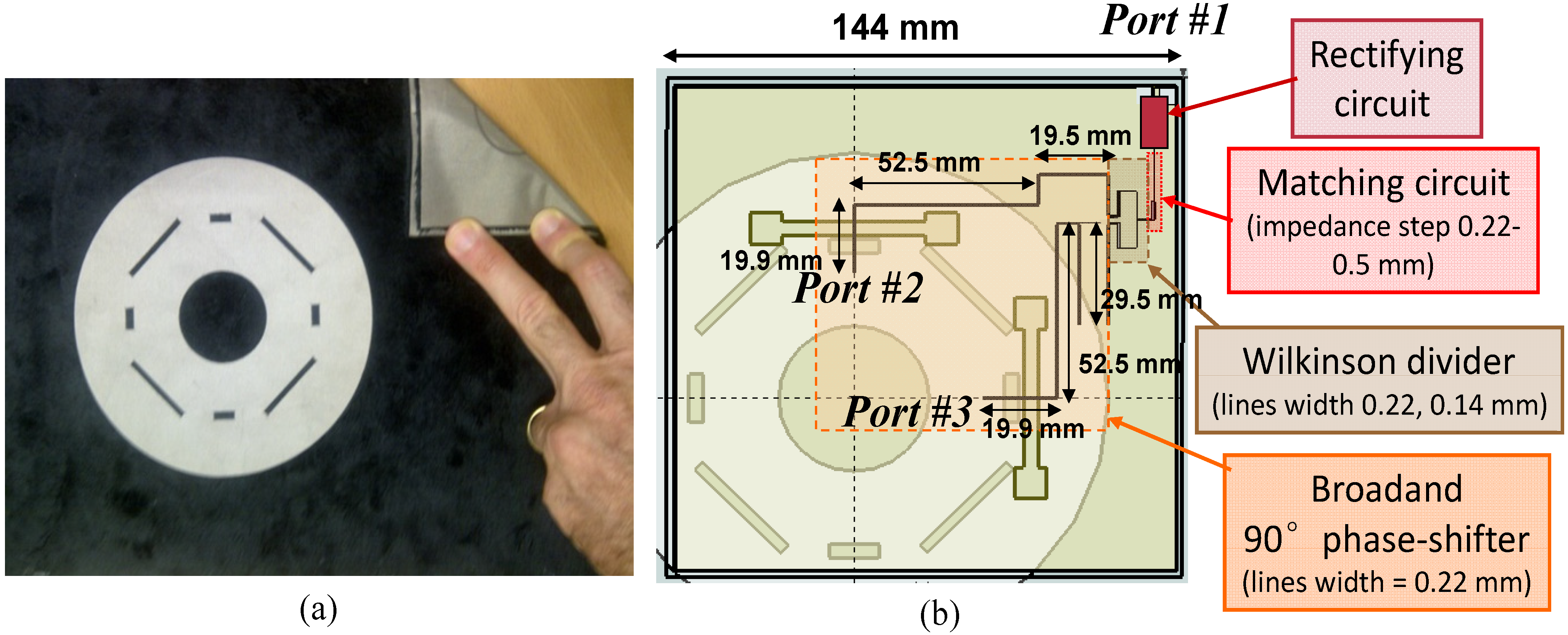
The multi-band linear feeding network design is first carried out at the circuit level, then layout-wise by means of a fine-tuning EM analysis. In both cases, the actual load offered by the antenna is taken into account: the resulting three-port network on a flexible Kapton layer (see
Figure 6b) consists of a broadband 90° phase shifter (for circular polarization purposes) and a power divider. The matching network topology (an impedance step, in this case) is obtained as the final result of the multi-band HB nonlinear optimization (see
Section 3.2).
The final layout of the multi-layered prototype is shown in
Figure 6a. Due to the placement of the antenna on a jacket (
Figure 3b), there is enough space for a large antenna ground plane: this improves the antenna directivity and reduces the human body effects.
Figure 6.
(a) Photo of the multi-layered rectenna prototype. (b) Layout of the three-port feeding network; Port 1 is in DC, while Port 2 and Port 3 are the RF antenna feeding ports needed for ensuring circular polarization.
Figure 6.
(a) Photo of the multi-layered rectenna prototype. (b) Layout of the three-port feeding network; Port 1 is in DC, while Port 2 and Port 3 are the RF antenna feeding ports needed for ensuring circular polarization.
3.2. Results
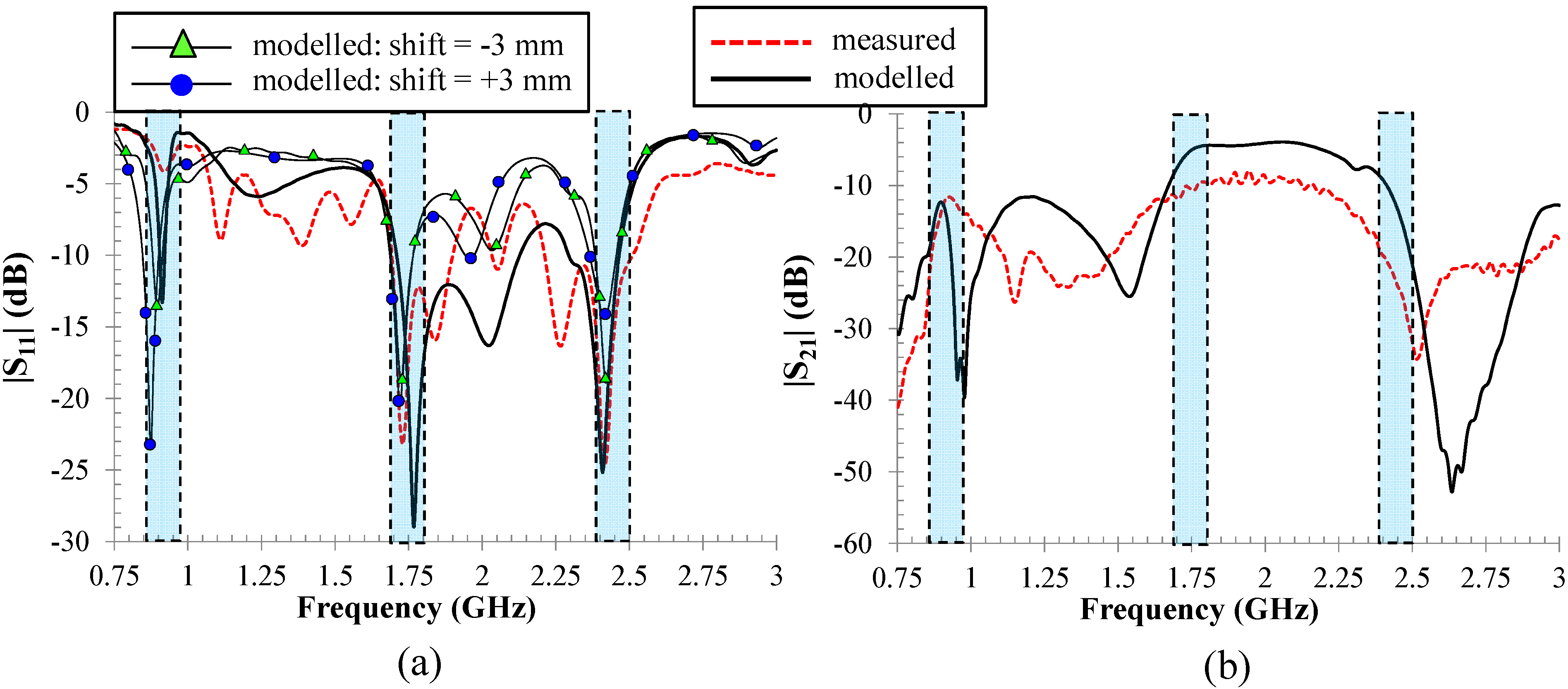
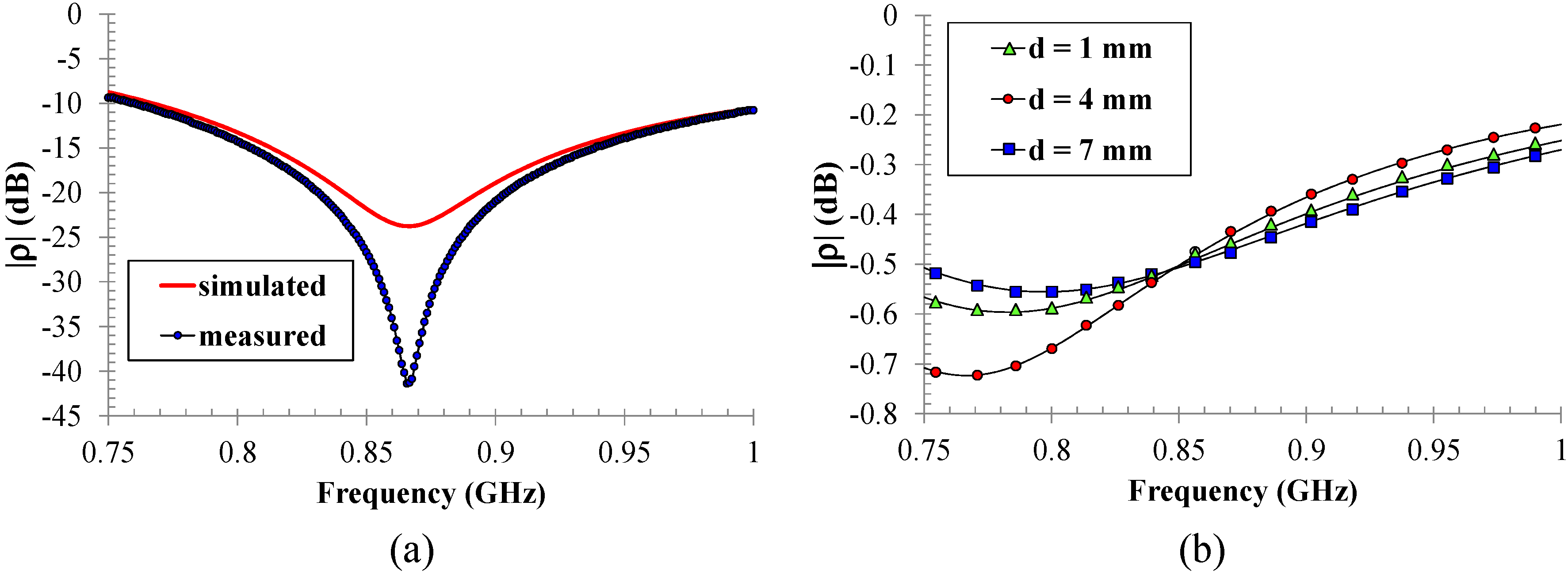
The performance of the two-port antenna in terms of scattering parameter behavior and radiation patterns at all of the frequency bands of interest are given in
Figure 7a,b and
Figure 8, respectively. A satisfactory agreement between measurements and simulations is obtained in both cases. A notable discrepancy occurs in terms of the reflection coefficient at 900 MHz: the sharpness of the corresponding resonance makes it the most delicate operating bandwidth, highly sensible to mechanical tolerances in ground aperture shape. The simulation of the two-port antenna with in-quadrature port excitation and a background plane area of 25 × 25 cm
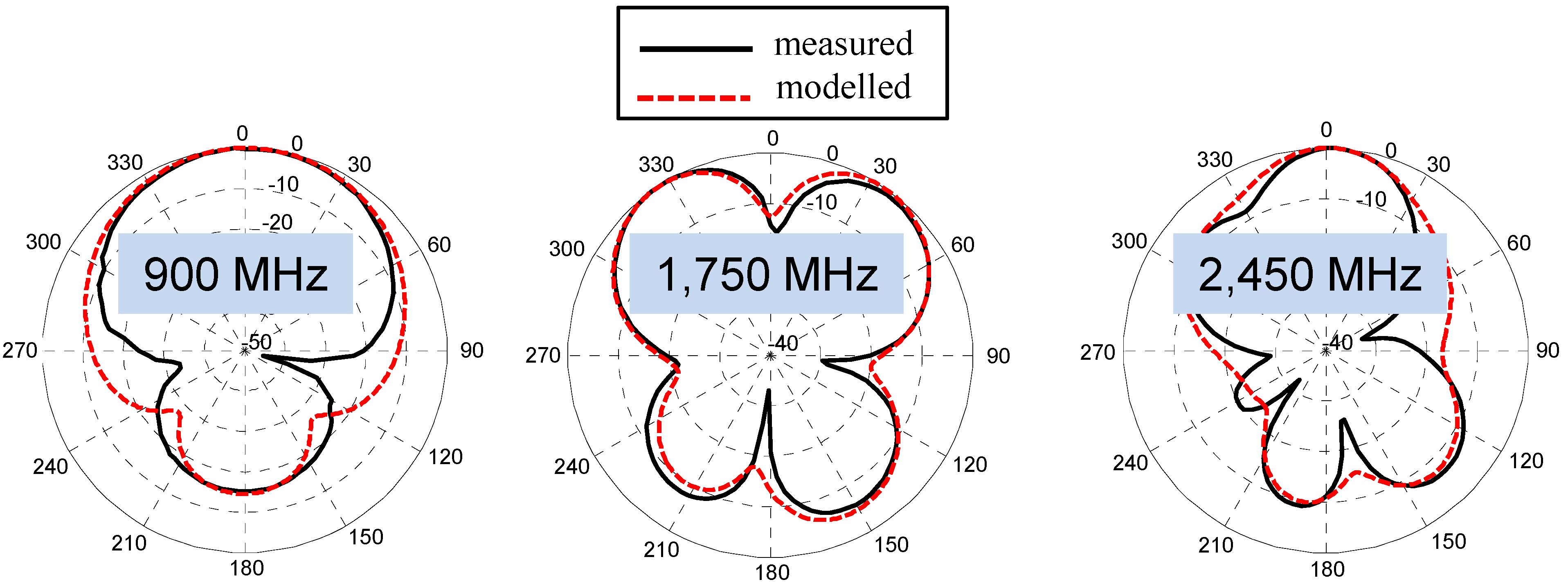
2 provides efficiencies of 61%, 54% and 85% in ascending frequency order and realized gains equal to 4.7, 4.9 and 9.1 dB, respectively. An axial ratio less than 3 dB is obtained for the TM11 and TM12 mode for a wide elevation range; the TM21 mode is unable to provide circular polarization due to the exact superposition of the excited orthogonal modes (see
Figure 5a).
Figure 7.
(a) Measured and simulated reflection coefficient of the two-port ring antenna and simulated reflection coefficient dependence on pile-Kapton substrate misalignment. (b) Measured and simulated transmission coefficient of the two-port ring antenna.
Figure 7.
(a) Measured and simulated reflection coefficient of the two-port ring antenna and simulated reflection coefficient dependence on pile-Kapton substrate misalignment. (b) Measured and simulated transmission coefficient of the two-port ring antenna.
Figure 8.
Measured and simulated radiation patterns of the two-port ring antenna at the three operating frequencies.
Figure 8.
Measured and simulated radiation patterns of the two-port ring antenna at the three operating frequencies.
Figure 7a also reports the effects of an unpredictable, but probable, misalignment between the antenna and the Kapton layers. This could happen during the manual attaching procedure, despite suitable markers realized on the layers: a ±3 mm shift is the over-estimated range of uncertainty. The modeled scattering parameters shown in the figure guarantee a sufficient robustness of the rectenna design with respect to unwanted asymmetries: the maximum resulting shift is about 4% for the lower frequency, which is the most susceptible band, as measurements have demonstrated.
Two further simulations are carried out addressing bending and human body effects. Firstly, the antenna and the feeding layers are bent around a vacuum cylinder with a 150-mm diameter, corresponding to a typical adult chest. No significant variations with respect to the flat configuration are observed, provided that no misalignment occurs. Secondly, the cylinder is filled with a human-body-like material (εr = 53.3 and σ = 1.52 S/m); the presence of the 25 × 25 cm2 back shielding fabric guarantees almost unchanged behavior, in this case, too.
Finally, a multi-band nonlinear optimization of the whole rectenna is carried out by the HB technique: design specifications are simultaneously given in terms of RF-to-DC conversion efficiency, at the three fundamental frequencies, by combining the frequency-dependent EM description of the antenna/phase-shifter with the nonlinear rectifying circuit. The latter consists of a single-stage, full-wave peak-to-peak RF-DC converter, as shown in
Figure 3c: this simple rectifier topology, employing low-threshold-voltage diodes (Skyworks SMS7630), minimizes diode losses and represents the best choice for ultra-low-power applications [
6,
25]. At this stage, the design parameters are provided by the matching network layout: in this case, it simply consists of a microstrip impedance step. The power levels pertaining to the equivalent current generator Equation (3) (or Equation (4)):
span the low-power range typical of scavenging scenarios (from few to few hundreds of μW), with ω
RF equal to 900, 1,800 and 2,450 MHz for the three bands application under exam.
Figure 9a finally provides the rectenna performance in terms of RF-to-DC conversion efficiency for the three operating frequencies, as a function of the power transmitted by a resonant dipole placed 30 cm away and in the maximum link direction. For the sake of clarity, the same figure also shows the corresponding RF available power abscissa axes: they obviously put into evidence the strong channel dependence on the operating frequency. Due to the adopted link distance, the field radiated by the dipole cannot be considered a uniform plane wave in the harvester location: for this reason, we resort to Equation (4) in the evaluation of Equation (5). The same figure reports also a good comparison with available measurements carried out in a real office scenario for typical low incident power levels. In more complex scenarios (
i.e., non-line-of-sight links), the inclusion in the CAD tool of the channel description is mandatory in order to obtain realistic predictions [
26].
Figure 9.
(a) Conversion efficiencies of the whole wearable rectenna at the three operating frequencies. (b) Rectified output voltage at the three operating frequencies and in the contemporaneous presence of the three tones.
Figure 9.
(a) Conversion efficiencies of the whole wearable rectenna at the three operating frequencies. (b) Rectified output voltage at the three operating frequencies and in the contemporaneous presence of the three tones.
The presented procedure allows us to simultaneously account for the presence of various RF sources by means of a nonlinear multi-tone HB analysis (as envisaged in
Figure 3), where the different tones are represented as independent rectenna excitations: intermodulation products up to the third order are considered in the HB simulation. In
Figure 9b, the rectenna output DC voltages resulting from the superposition of different sources (solid line) and from single sources are compared, again as a function of the incident transmitted power. The transmitted power values of the figure are associated with one excitation in the single-tone analysis and are equally distributed across the different tones in the multi-tone case. It is worth noting that, at low power levels, the deployment of the intermodulation products generated by the nonlinearities improves the rectenna conversion capabilities. At higher levels, this effect is negligible.


