1. Introduction
The use of embroidered conductive thread to produce a range of radio frequency antenna systems has become popular since the late 1990s when conductive fabrics began to be used for wearable systems. Initially used for Direct Current to low frequency and for shielding applications [
1], their obvious potential for higher frequency systems became clear in the early part of this century [
2]. These systems are now becoming commonplace for use as GPS, Mobile Phone and Radio Frequency Identification (RFID) [
3,
4,
5,
6,
7] antennas to which they are ideally suited. It should be noted however that regular washing of such conducting yarns does lead to degradation in the electrical properties [
8]. An application which has, until now, remained unexplored is the use of conductive fiber coils in magnetic resonance imaging.
Pulsed nuclear magnetic resonance (NMR) and magnetic resonance imaging (MRI) are well established techniques most commonly associated with large scanners. In recent years the availability of low field strength (<1 Tesla) unilateral (single-sided) NMR probes [
9,
10,
11,
12], based on simple rare earth permanent magnets, has been accompanied by an increase in the number of low cost NMR consoles (the electronics used to drive them). Applications have also diversified as a result of more affordable hardware [
13,
14,
15]. All pulsed magnetic resonance systems face the same challenge: a large power is needed to excite the sample (1–1000 W) whilst the collected signal is typically less than a micro-Watt.
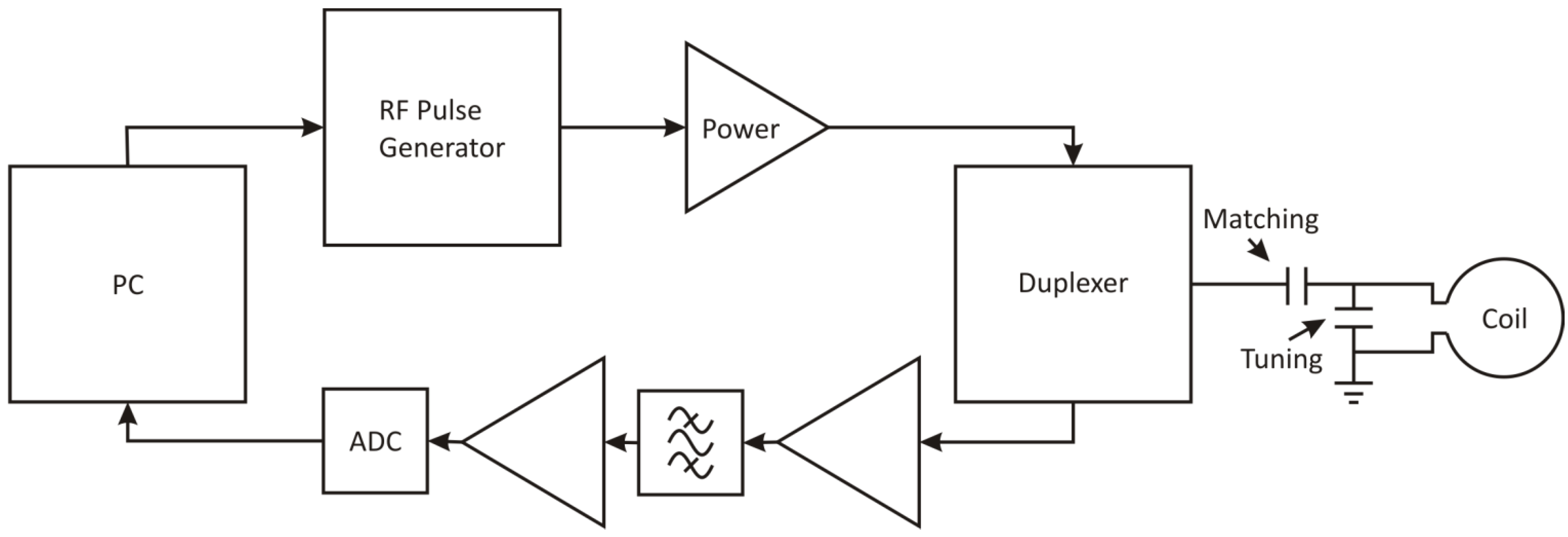
Figure 1 shows the elements required to obtain an NMR signal from a sample. For transmission, RF pulses are generated at low power and amplified to the required level to excite the sample when delivered to the NMR probe (containing an impedance matching circuit and sample coil). The small radio frequency signal produced by the sample is then induced into the same (or a closely placed) coil which is connected to a low noise preamplifier that produces a signal suitable for the RF detection stage allowing digital or analogue processing. A duplexer is used as a transmit receive switch to protect the preamp during transmission and to reduce noise by isolating the transmitter during reception.
Figure 1.
Schematic diagram of a typical pulsed nuclear magnetic resonance (NMR) system showing components and impedance matching circuit.
Figure 1.
Schematic diagram of a typical pulsed nuclear magnetic resonance (NMR) system showing components and impedance matching circuit.
The NMR probe usually consists of a coil with a tuning capacitor in parallel with the coil and, a matching capacitor in series with the coil, allowing the probe to apply and receive high frequency energy to and from a sample of interest in a magnetic field [
16,
17]. This is usually achieved with copper coils placed around the sample in rigid housings. Most often a single coil is used to both excite the sample and to collect the resultant signal, whilst for more sensitive studies separate coils are used. These can be made of copper on flexible substrates in order to decrease the separation between the sample and the coil as proximity and conformity of the coil are critical parameters in maximising the SNR. In this paper we present a fundamental demonstration of the principles of using an embroidered conductive fabric coil for magnetic resonance.
2. Experimental Section
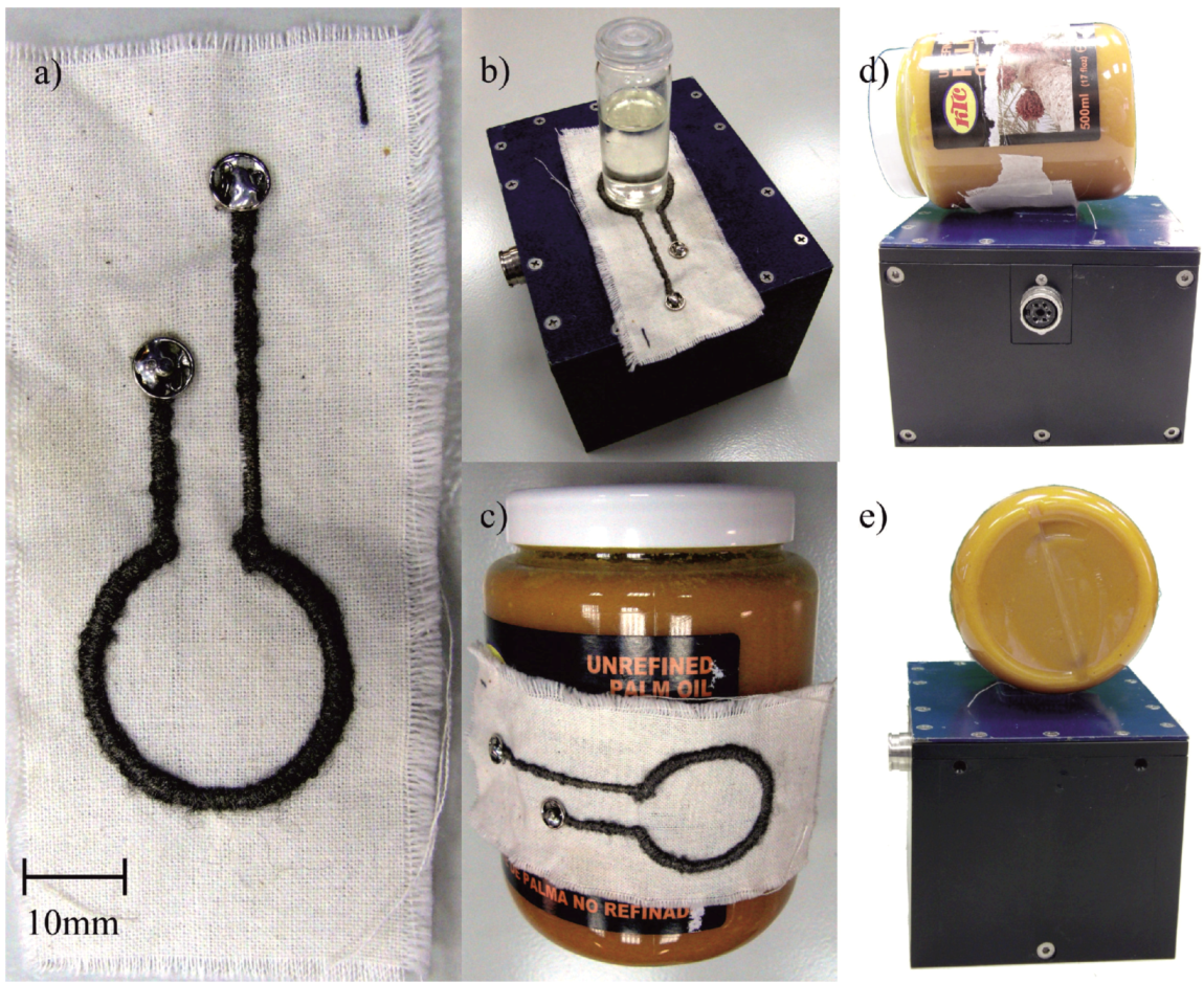
A simple single loop coil of diameter 24.5 mm was produced using silver coated nylon yarn embroidered using a stitch length of 0.2 mm on a Barudan BEVT-Z1501CB digital embroidery machine modified to minimize the damage to the delicate yarn during application. This was embroidered onto a woven cotton fabric and protruded 1.1 mm either side of the cotton layer giving a coil resistance of 9.2 Ω. A number of different designs were investigated however all these exhibited much higher resistance values (reducing the maximum achievable quality factor) and did not result in a sufficient impedance match at the required frequency. A photo of the selected design is shown in
Figure 2 along with photographs of its use for measurements.
Figure 2.
(a) Photograph of the embroidered coil; (b) The coil flat on the NMR MOUSE™; (c) Embroidered coil conformed to palm oil tub; (d) The coil and tub on the NMR MOUSE™ from the front, and (e) the side.
Figure 2.
(a) Photograph of the embroidered coil; (b) The coil flat on the NMR MOUSE™; (c) Embroidered coil conformed to palm oil tub; (d) The coil and tub on the NMR MOUSE™ from the front, and (e) the side.
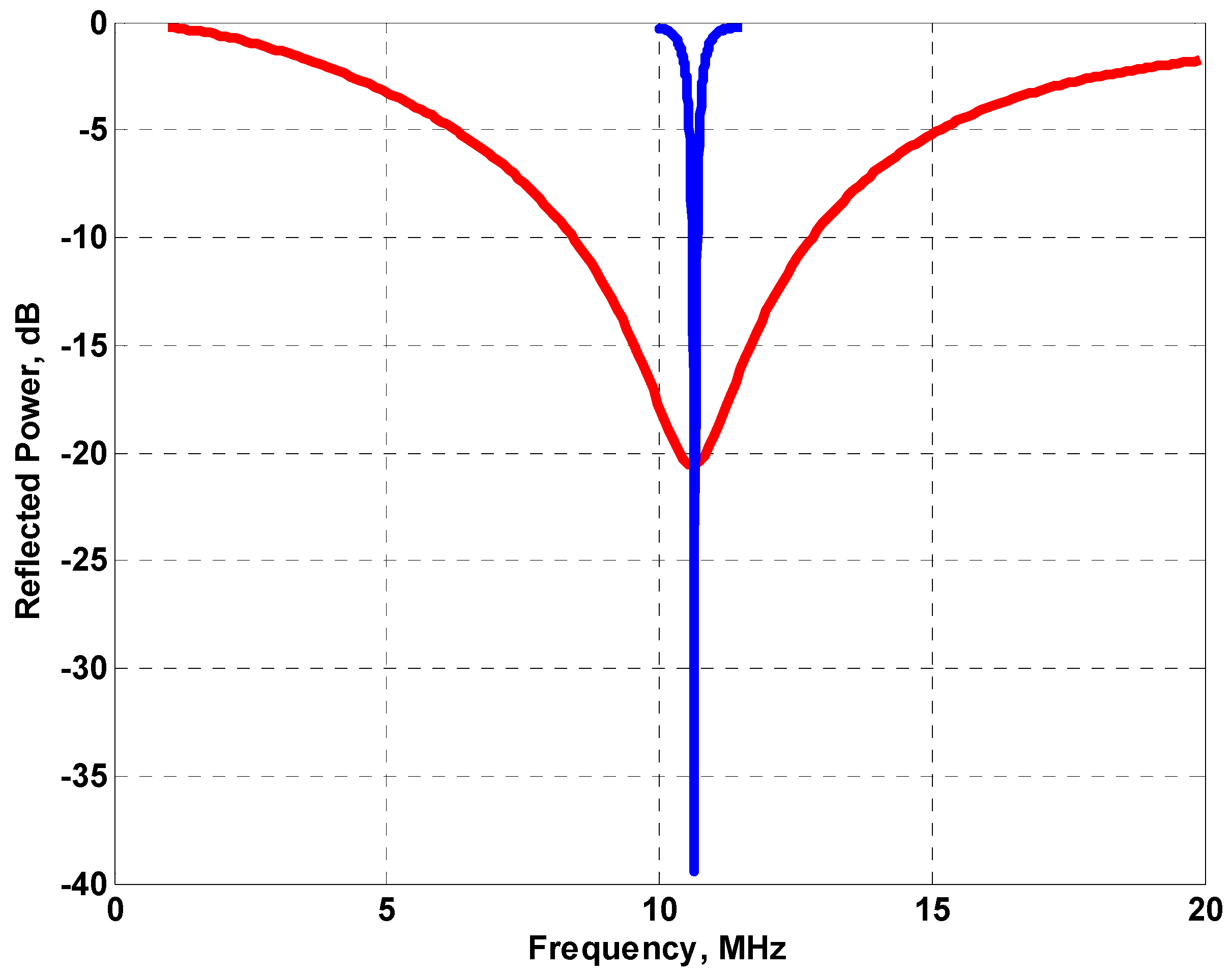
The coil, tuning and matching capacitors were connected to a network analyzer (Agilent E5061A) that scans through the frequency range of interest showing the resonant properties of the circuit.
Figure 3 shows the data for the fabric coil with a broad resonance centered at 10.64 MHz. The commercial magnetic resonance instrument used in this work was the ACT (Aachen) profile NMR MOUSE™ [
18] with a CAT-20 Apollo (Tecmag, Houston, TX, USA) console to provide pulse sequence generation and signal processing with a Tomco (Stepney, Australia) BT00250-Beta 250 W power amplifier. The instrument operates at a frequency of 10.64 MHz and uses the same coil for excitation and detection. The system is unilateral and provides a uniform magnetic field (which defines the sensitive volume being interrogated by the system), 5 mm above the top surface and with dimensions 5 μm × 30 mm × 30 mm.
The resonance curve for the built in coil on the MOUSE™ is also shown in
Figure 3. The much sharper resonance would be expected to deliver energy much more efficiently to the sample than the broader resonance of the fabric coil. For this particular application however, the broad resonance is advantageous in that changes in the shape of the coil when it conforms to the object being measured do not cause much variation in the tuning of the circuit. The loss in matching is predominantly due to the increased resistivity of the fabric coil compared to that of the NMR MOUSE™. It may be possible to improve this by using a different yarn although that has not been explored as part of this work. The Carr Purcell Meiboom Gill (CPMG) [
19] sequence was used to measure T
2eff, as is typical on unilateral instruments, with a saturation recovery sequence used for the determination of T1 [
20]. The parameters used for these sequences are detailed in
Table 1. Prior to these measurements a series of Carr Purcell Meiboom Gill (CPMG) sequences with increasing 90 degree pulse length were run to find the maximum signal and hence the optimum time for the 90 degree pulse; this was found to be 6000 ns and was significantly longer than the 4500 ns for the MOUSE™ coil (for the same RF transmit power of 250 W) as expected given the lower quality factor and the difference in the geometry of the coils.
Figure 3.
The resonance curves for the fabric coil probe (red line) and the NMR MOUSE™ probe (blue line).
Figure 3.
The resonance curves for the fabric coil probe (red line) and the NMR MOUSE™ probe (blue line).
Table 1.
Parameters used for MR measurements.
Table 1.
Parameters used for MR measurements.
| Parameters | Values |
|---|
| 90° Pulse Length (Copper) | 4500 ns |
| 90° Pulse Length (fabric) | 6000 ns |
| Echo Time | 300 μs |
| Repetition Time | 600 ms |
| Number of Echoes | 128 |
| Dwell Time | 1 μs |
| Points per Echo Window | 80 |
The longer pulse length will also result in a slight reduction in the volume of the selected slice due to the reduction in the bandwidth. The test samples used were sunflower oil and red palm oil. For investigating how well the fabric conforms to different surfaces and how this affects the measurements, a tube was used filled with red palm oil with a diameter of 8 cm. Wrapping the coil round the 8 cm tube, resulted in no measureable change in the frequency at which the minimum occurred in the resonance curve on the network analyzer. Even wrapping the coil as tightly as round a 2.5 cm tube resulted in a change in resonant frequency of less than 500 kHz which is a small change compared to the width of the resonance and thus would not require retuning. For the 2.5 cm tube, very little of the sample would be in the sensitive volume of the magnet due to the curvature of the sample so this is not presented. In the highly uniform field of a conventional MRI scanner however it would not show the reduced measurement volume that is experienced with a unilateral instrument.
3. Results and Discussion
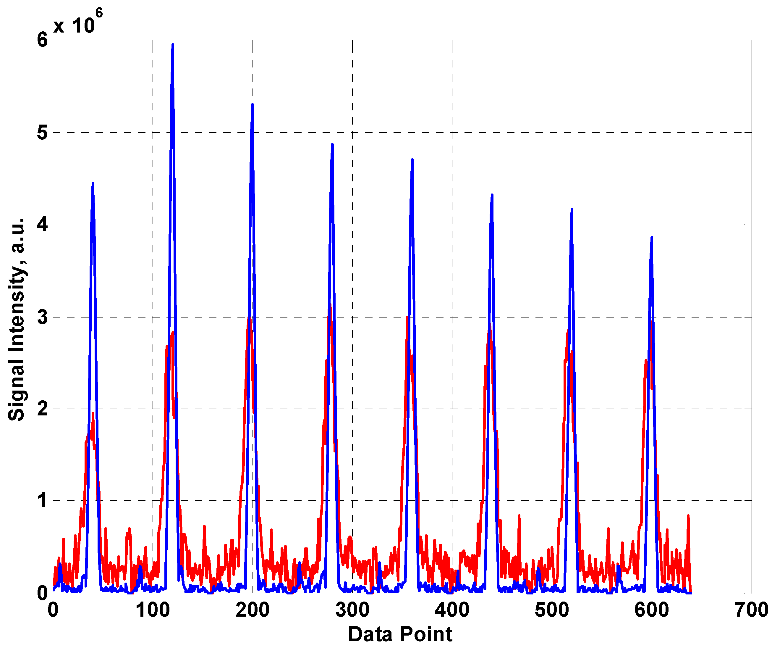
The first eight spin echoes taken from a CPMG sequence are shown in
Figure 4 with 1024 averages using the fabric coil (red) and the built in coil from the NMR MOUSE™ (blue). As is usual for this type of unilateral system, the first (Hahn) echo is significantly smaller than subsequent echo train as it is heavily influenced by diffusive motion. The signal is clearly much lower for the fabric coil which can be accounted for by the sharper resonance of the MOUSE™ coil resulting in more efficient generation and detection of the RF signal. In addition, the width of the echoes is significantly greater for the fabric coil. The SNRs of the two systems were estimated (using peak signal/standard deviation of surrounding noise for the real component of the 4th echo) as 17 and 61 for the fabric coil and the MOUSE™ coil respectively.
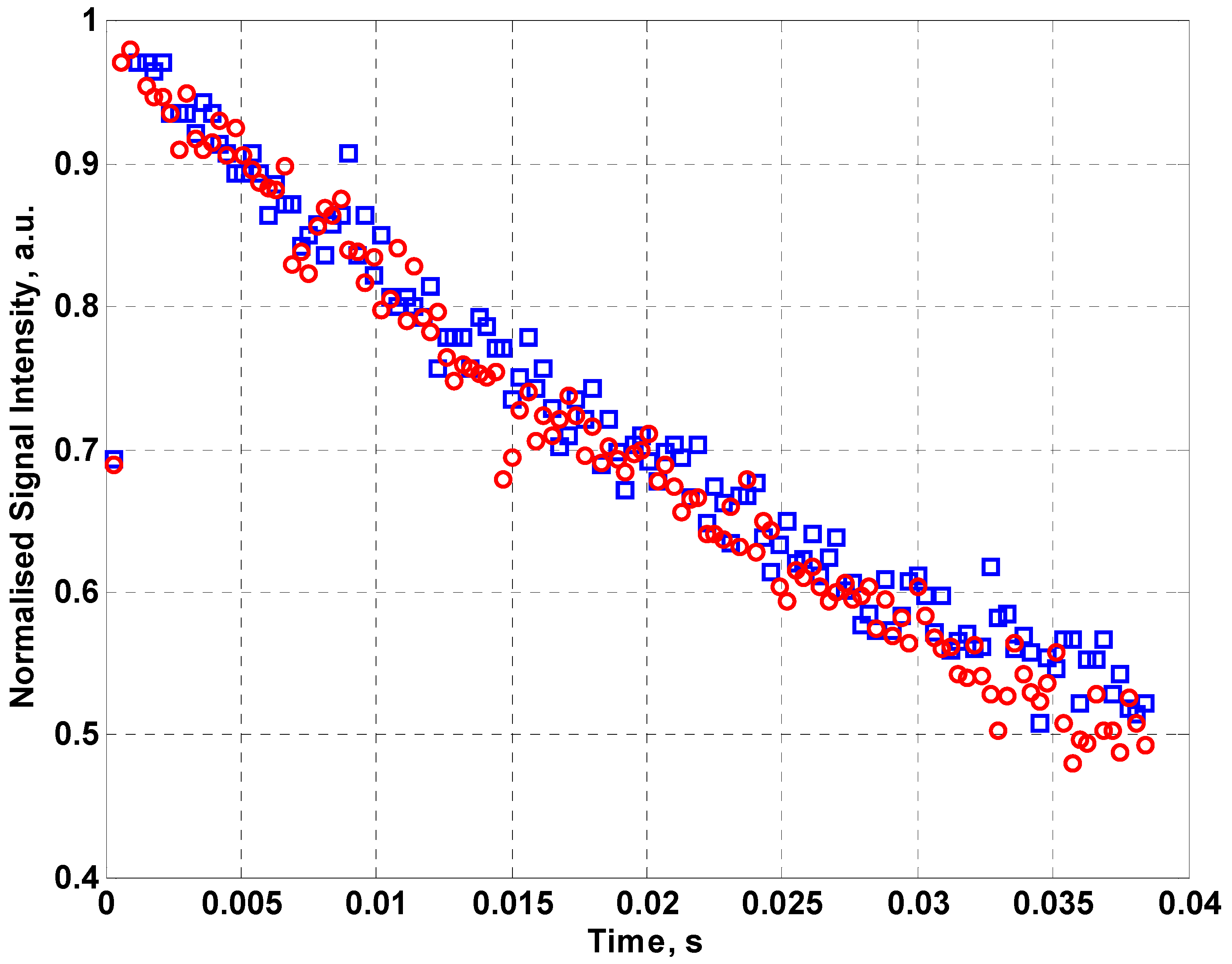
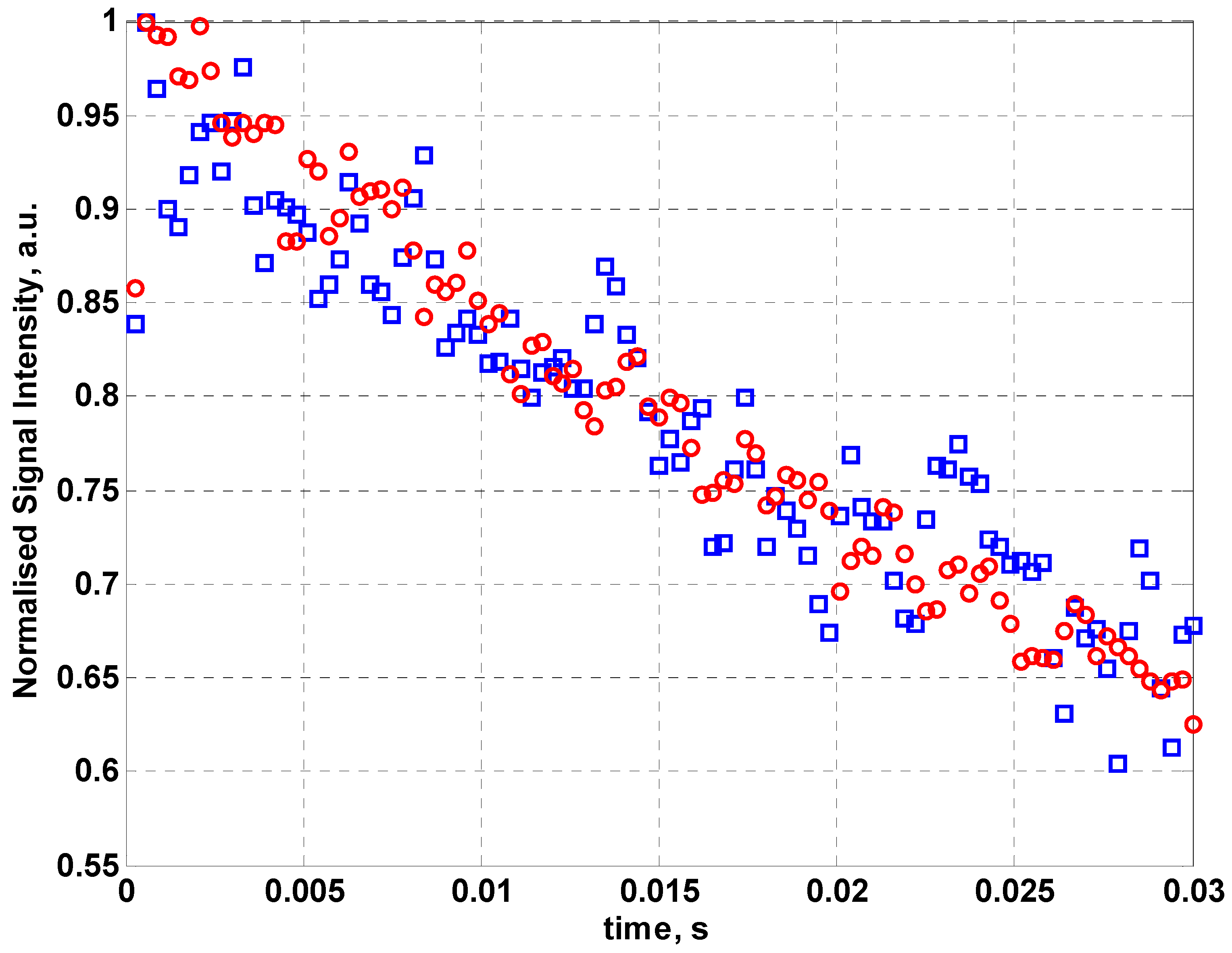
Figure 5 shows the normalized NMR signal intensity for fabric coil for a 128 echo CPMG sequence using sunflower oil as the sample. By fitting an exponential curve to the data, values for the effective transverse relaxation time T
2eff can be found. From the data in
Figure 5, T
2eff for sunflower oil is 58.1 ± 5.3 ms compared to 55.68 ± 2.5 ms for the inbuilt coil of the NMR MOUSE™. The error in the relaxation time has been determined from the exponential fit to the data. This demonstrates that a fabric coil can be used for measurements of relaxation time although it requires more averaging than the optimized commercial copper coil.
Figure 4.
The first eight echoes produced by a CPMG sequence using (a) the fabric coil (red line) (b) the MOUSE™ coil (blue line).
Figure 4.
The first eight echoes produced by a CPMG sequence using (a) the fabric coil (red line) (b) the MOUSE™ coil (blue line).
Figure 5.
The normalized NMR signal intensity for the MOUSE™ coil (red circles) and fabric coil (blue squares) for a 128 echo CPMG sequence using sunflower oil as the sample.
Figure 5.
The normalized NMR signal intensity for the MOUSE™ coil (red circles) and fabric coil (blue squares) for a 128 echo CPMG sequence using sunflower oil as the sample.
The fabric coil was then used to measure the relaxation times for red palm oil initially with a flat coil and then with it wrapped around an 8 cm diameter tube.
Figure 6 shows the normalized signal intensity for a train of 128 echoes with 512 averages for a CPMG sequence for the flat fabric coil (squares) and the same coil wrapped round the 8 cm tube (circles). By fitting an exponential curve to the data, the flat fabric gives T
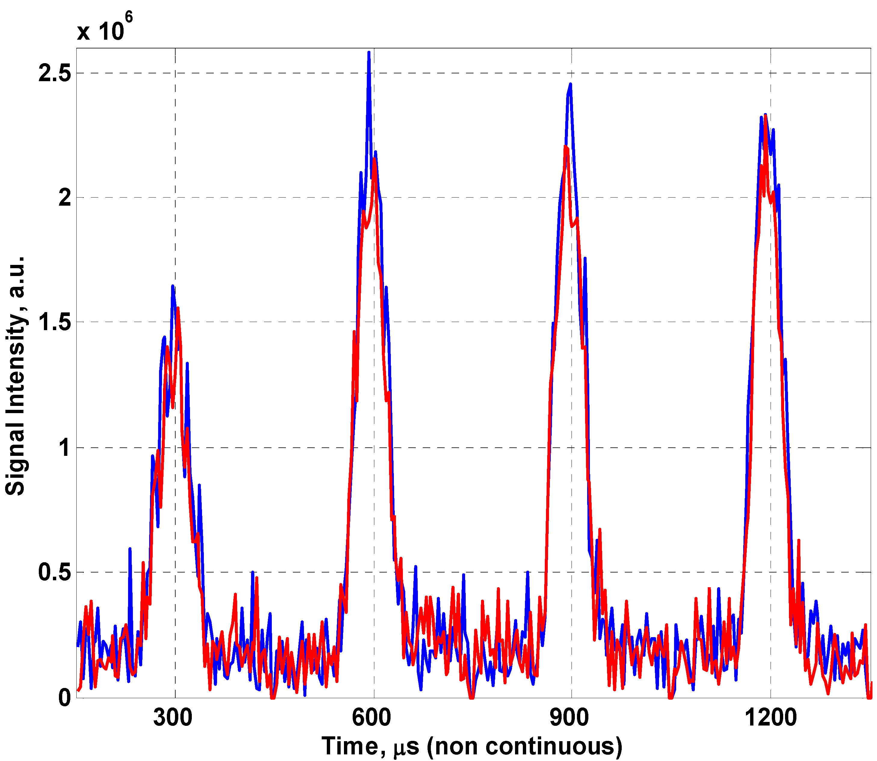
2eff of 60.5 ± 2.8 ms, whilst wrapped round the 8 cm tube gives 55.8 ± 2.8 ms. To better demonstrate the variation in signal quality between the coil flat and conformed to a cylinder,
Figure 7 shows the first four spin echoes produced for the fabric coil lying flat on the MOUSE™ and conformed to the red palm oil tube (8 cm in diameter), this results in a minor loss in signal due to the change in geometry. The thin slice of magnetic homogeneity prevents us from seeing an improvement in the fill factor of the coil (the ratio of the sample volume of interest to the sensitive volume of the coil) which would likely negate this effect in a traditional MRI scanner.
Figure 6.
The normalized NMR signal intensity for 128 echo CPMG sequence with 512 averages for red palm oil using flat fabric coil (red circles) and the fabric coil wrapped round the 8 cm tube (blue squares).
Figure 6.
The normalized NMR signal intensity for 128 echo CPMG sequence with 512 averages for red palm oil using flat fabric coil (red circles) and the fabric coil wrapped round the 8 cm tube (blue squares).
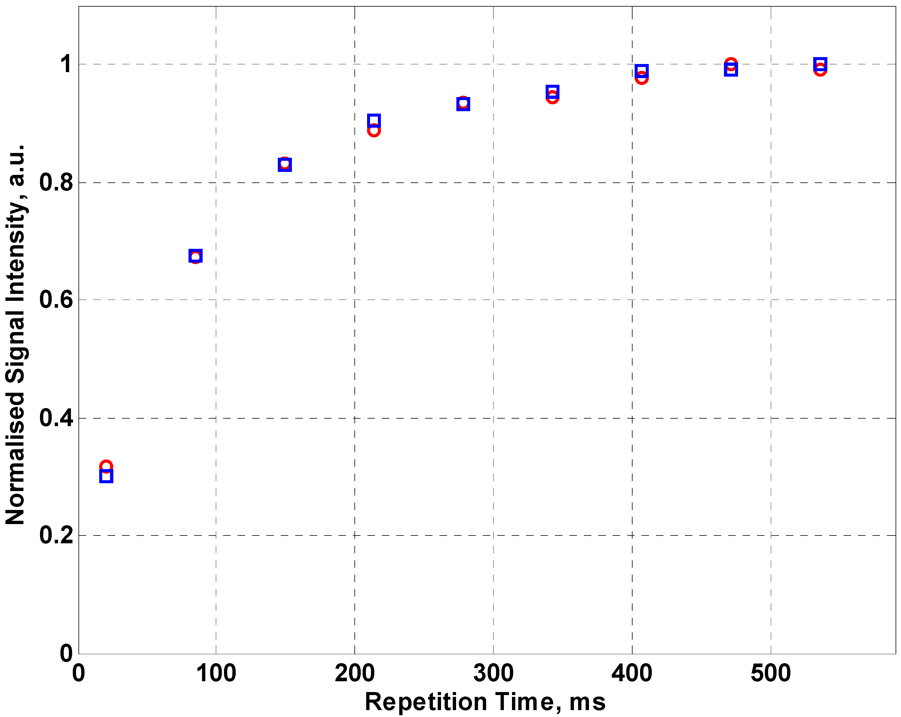
In addition to measuring T
2eff, increasing repetition times were used to determine T
1 for the red palm oil and used a 128 echo train and 512 averages with the normalized data presented in
Figure 8. The flat fabric (squares) gives T
1 of 100.6 ± 0.8 ms, whilst wrapped around the 8 cm tube (circles) gives 103.6 ± 0.8 ms. Given that sunflower oil and red palm oil are natural materials with some spatial variation expected in measured relaxation times, the values of T
1 and T
2eff are within the expected experimental measurement range.
Figure 7.
Raw spin echoes comparing the fabric coil flat (blue) and conformed (red) to an 8cm cylinder.
Figure 7.
Raw spin echoes comparing the fabric coil flat (blue) and conformed (red) to an 8cm cylinder.
Figure 8.
Normalized data for a saturation recovery sequence for the red palm oil used a 128 echo train and 512 averages. Data for the flat fabric coil is shown as red circles whilst the fabric coil wrapped round the 8 cm tube is shown as blue squares.
Figure 8.
Normalized data for a saturation recovery sequence for the red palm oil used a 128 echo train and 512 averages. Data for the flat fabric coil is shown as red circles whilst the fabric coil wrapped round the 8 cm tube is shown as blue squares.
4. Conclusions
We have demonstrated the ability to use an embroidered coil as a substitute for a traditional copper coil in an MR system. The measured signal levels are smaller than the commercial instrument due to the lower Q factor of the coil which therefore requires more averaging to achieve the same SNR. The higher coil resistance results in the poorer quality factor of the coil and is ultimately responsible for the reduction of SNR in comparison to the copper coil. By using a more conductive yarn than that which we have used, using a thicker thread, changing the stitch pattern, or producing a different coil geometry, it should be possible to reduce this resistance to the point at which the achievable in increase in fill factor improves the SNR in comparison to a copper coil. However, even with the current yarn, the ability to embroider such coils on textiles (flexible substrates) will allow this same technique to be applied to samples in which it is desirable to have a soft conformable coil such as cranial imaging or elastomer based limb coils within a medical magnetic resonance imaging scanner or as a low cost disposable technology. We have demonstrated for the first time that it is possible to perform a magnetic resonance experiment using an embroidered coil.


