Article

A Multiple-Sensor Fault-Tolerant Control of a Single-Phase Pulse-Width Modulated Rectifier Based on MRAS and GPI Observers

1
LR11ES15 Laboratoire des Systèmes Electriques, Ecole Nationale d’Ingénieurs de Tunis, Université de Tunis El Manar, Tunis 1002, Tunisia
2
Sapienza Electric Machines and Power Electronics Research Group (SEMPER), Department of Astronautical, Electrical and Energy Engineering, University of Rome ‘La Sapienza’, 00185 Roma, Italy
*
Author to whom correspondence should be addressed.
Electronics 2024, 13(3), 502; https://doi.org/10.3390/electronics13030502
Submission received: 12 December 2023 / Revised: 16 January 2024 / Accepted: 18 January 2024 / Published: 25 January 2024
(This article belongs to the Topic Power Converters)

Abstract

:
Due to their advantages in ensuring low harmonic distortion and high power factors, single-phase Pulse-Width Modulated (PWM) rectifiers are widely employed in several industrial applications. Generally, the conventional control loop of a single-phase PWM rectifier uses both voltage and current sensors. Hence, in case of sensor fault, the performance and the availability of the converter can be seriously compromised. Therefore, diagnosis approaches and fault-tolerant control (FTC) strategies are mandatory to monitor these systems. Accordingly, this paper introduces a novel multiple-sensor FTC scheme for a single-phase PWM rectifier. The proposed fault diagnosis approach relies on joining several Generalized Proportional Integral (GPI) and Model Reference Adaptive System (MRAS) observers with a residual generation technique to detect and isolate sensor faults in a simple and reliable manner. While conventional sensor FTC methods dedicated to PWM rectifiers can only deal with single faults, the suggested approach guarantees a very good effectiveness level of sensor fault detection, isolation (FDI) and FTC of multiple-sensor fault occurrence scenarios. Consequently, the single-phase PWM rectifier can work with only the survivable single sensor with the guarantee of very good performance as in healthy operation mode. The effectiveness of the proposed sensor FDI approach and its control reconfiguration performance are demonstrated through both extensive simulation and experimental results.

1. Introduction

In recent years, Pulse-Width Modulation (PWM) Rectifiers have arisen as one of the most important components in various industrial applications such as renewable energy [1,2,3], EVs [4,5], electric traction [6,7,8], and so on. They ensure several advantages such as sinusoidal input currents, stable DC-Link voltage and unit power factor [9,10].
For such applications, downtimes caused by different types of failures have a direct impact on the productivity of the system as well as on production costs. Hence, ensuring reliability is becoming an issue of utmost importance. The overall components of the system should be monitored to avoid any possibility of performance degradation due to faults. According to this understanding, fault-tolerant control policies are currently needed more than ever to ensure the system functioning even under fault occurrence.
During the last years, fault diagnosis and fault tolerance of PWM rectifiers have been important research topics that still present challenges, as addressed by several recent publications [11,12,13,14,15,16,17,18,19,20,21,22,23,24,25,26,27,28,29,30,31,32,33]. Apart from failures occurring in the power semiconductors [11,12,13,14], a grid-connected voltage source converter is also sensitive to failures in the sensors that provide vital information used by the main control system. In this context, the continuity of service of the system depends intimately on the availability of reliable measurements.
Regarding sensor FDI and FTC issues in single-phase grid-connected converters, several studies have been conducted. State observers have been investigated for a robust sensor fault-tolerant control of single-phase PWM rectifiers [15,16,17,18,19]. In [15], a Luenberger observer (LO)-based FDI is presented to allow DC-link and grid current sensors fault tolerance. After fault detection and isolation, the fault reconfiguration procedure is based on an open-loop state estimator. The stability and robustness of the observer during parameter variation are verified. Poon et al. [16] addressed a model-based state estimator general FDI approach that can be used to diagnose and identify faults in components and sensors in switching power converters. In [17], an open-loop state estimator is developed for the detection of grid current and DC-link voltage sensors for a single-phase grid-connected PWM rectifier. Scaling and offset and drift fault detection have been investigated. However, the proposed approach may be sensitive to the system’s parameters’ mismatch. Unknown input observers for sensor fault detection and localization are presented in [18]. A reduced-order observer-based resilient control for single- or multiple-sensor faults for cascaded H-bridge multilevel converters is provided in [19]. Grid current and DC-link voltage sensor faults are considered, and five types of faults for each sensor are investigated.
Xia et al. [20] proposed a sliding-mode observer (SMO)-based algorithm for the fault detection and fault reconfiguration of catenary current and DC-link voltage sensor faults of a single-phase PWM rectifier for electric traction applications considering unipolar and bipolar modulation methods. A similar approach is discussed in [21], where the sliding-mode observer design is improved by considering the DC load current as an unknown input of the observer. In [22], an incipient voltage sensor fault isolation method is developed for a single-phase three-level rectifier. A bank of sliding-mode and adaptive estimators was designed in order to isolate different DC-link voltage sensor fault modes. However, only FDI is discussed, and the FTC is not presented. An interval estimator and a sliding-mode estimator have been designed in [23]. The proposed estimator was used for an incipient sensor fault detection method for a class of nonlinear control systems with observer-unmatched uncertainties. The voltage and current sensor fault-tolerant control of the LC branch in the active power decoupling single-phase PWM converter through SMO are discussed in [24]. In [25], a robust control strategy for a three-phase grid-tied inverter with an LCL filter under grid voltage and grid current sensor faults is presented. A quadrature filter of a dual second-order generalized integrator (DSOGI) architecture is used for the grid current estimation. An internal model-based estimator is proposed for grid voltage estimation. A fault-tolerant space-vector hysteresis current control for a three-phase grid-connected converter is discussed in [26]. The analytical redundancy introduced by the use of three measurements allows the continuous work of the system. The parity space equations and virtual flux estimation have been discussed to ensure grid voltage sensor fault tolerance in [28], whereas a hybrid model-based and data-driven method is proposed for the grid current sensor fault-tolerant control [29].
In addition to residual generation-based FDI approaches, fault estimation (FE)-based approaches have gained more and more interest during the last years [30,31,32]. A state observer fault estimation to compensate for DC-link voltage and catenary current sensor faults for a single-phase two-level PWM rectifier in a high-speed railway electric traction system has been proposed in [30]. In [31], a grid current sensor fault estimation and compensation for a grid voltage sensorless single-phase grid-connected converter using proportional integral observers is described. A robust grid voltage sensor FE based on an unknown input observer with disturbances decoupling is addressed in [32].
The state-of-the-art review has shown that the research field of sensor FTC in electrical power converters is still very attractive with many challenging issues. Recently, more attention has been paid to the use of data-driven approaches for fault diagnosis purposes. In [33], a just-in-time learning (JITL) and modular Bayesian network (MBN) is proposed to diagnose sensor faults in a high-speed electric railway traction application, whereas the time series feature patterns of a single-phase PWM rectifier are employed to identify several types of faults such as the following: traction transformer faults, traction converter faults, main grid poor contact or inrush current [34]. Zhu et al. [35] presented an automatic crack damage diagnosis in hydraulic structures by combining computer vision and artificial intelligence. Long short-term memory networks and phase space reconstruction are used for the prediction of a dam deformation [36]. Data-driven-based methods are of great interest for fault diagnosis or predictive maintenance purposes. Nevertheless, they are still not able to handle the fault tolerance step, and the use of estimators/observers is very useful for the continuous operation of the system under sensor faults. In this way, model-based and signal-based methods are still very welcomed to ensure reliable and effective sensor fault tolerance [37].
Moreover, multiple-sensor fault-tolerant control is becoming an attractive research topic but is still limited to three-phase induction motor drives [38] or PMSM drives [39]. The single-phase PWM rectifier’s control requires mainly three sensors [15]: one grid voltage sensor, one grid current sensor and a DC-link voltage sensor, as depicted in Figure 1. The state-of-the-art review demonstrates that the previously proposed sensor FTC methods are focused on single-sensor faults only, in particular on the grid current sensor and the DC-link voltage sensor. Indeed, the design of an FTC approach that takes into account the faults in the three sensors has not received much research attention yet. To the best knowledge of the authors, very few contributions have discussed multiple-sensor fault tolerance of a single-phase PWM rectifier [19]. On the other hand, the proposed FTC methods provided by the literature need accurate knowledge of the load current [15,20,30]. Hence, a load current sensor [15] or a load current observer [24] is mandatory, which may increase the system’s cost and the FTC algorithm complexity. In this context, a robust sensor FDI and FTC approach focused on the three sensors of the PWM rectifier and able to tolerate multiple-sensor faults is of great significance and may considerably contribute to improving the availability and safety operation of the studied system.
To address the problem of multiple-sensor fault-tolerant control for single-phase PWM rectifiers, this paper proposes a new structure that aims to ensure a simple, reliable and robust single- and multiple-sensor fault detection and fault-tolerant control of a single-phase PWM rectifier. The main features and contributions of this work are:
(1)
The proposed method is capable of tolerating single- or multiple-sensor faults, and the rectifier’s control loop can be driven by the single survivable sensor. For this purpose, two multiple-sensor fault-tolerant controls are investigated. In the first scenario, a DC-link voltage sensor fault followed by a grid voltage sensor fault is discussed. In the second scenario, a DC-link voltage sensor fault followed by a grid current sensor fault is investigated.
(2)
For this purpose, a residual generation-based FDI approach is presented. Hence, a bank of two Generalized Proportional Integral Observers (GPIO) and one Model Reference Adaptive System (MRAS) observer are developed in order to accurately estimate the grid voltage, the DC-link voltage and the grid current, respectively. Once the residual exceeds its corresponding threshold, a fault flag switches from 0 to 1 and the faulty sensor is identified. Thereafter, the faulty measurement is substituted by the virtual sensor into the rectifier’s control loop, to guarantee the continuous work of the rectifier.
(3)
The proposed FTC approach does not need any additional sensors, in particular load current sensors. Hence, in this work, the load current is considered as an unknown disturbance. It should not have any impact on the performance of the proposed FTC approach, neither in healthy operation nor during sensor post-fault operation of the system. Moreover, the system’s parameters’ mismatch, including grid-side filter inductor and DC-link capacitance, does not affect the robustness of the proposed method.
(4)
During sensor post-fault operation, the proposed FTC method allows the start-up of the process with the single survivable sensor with good accuracy and the same performance of the closed-loop control as in healthy operation mode.
(5)
The effectiveness of the proposed method is demonstrated through extensive simulation and experimental studies. The proposed FDI/FTC approach can be deployed on the commonly used digital controllers, improving the cost and the performance of real-time control of single-phase PWM converters in several industrial applications.
The paper is organized as follows: First, in Section 2, the single-phase PWM rectifier model and its control strategy are presented. Section 3 is devoted to analyzing the design of the different GPI and MRAS observers. FDI and FTC techniques are discussed in Section 4. Simulation results are carried out in Section 5. The experimental validation of the proposed FDI and FTC algorithm is discussed in Section 6. Finally, the paper is summed up in a conclusion in Section 7.

2. Mathematical Model of the Single-Phase PWM Rectifier and Control Strategy

The system under study and its control strategy are presented in Figure 1. The single-phase PWM rectifier can be modelled using the following equations:
V g = R i g + L d i g d t + V a b i c = i d c + i L = C d V d c d t V a b = S 1 S 3 V d c i d c = S 1 S 3 i g
where ig is the grid current, Vg the grid voltage, Vab is the rectifier input voltage, Vdc is the DC-link voltage, idc is the DC-side output current, ic is the current in the DC-side capacitor, iL is the load current and S1 and S3 are the binary switching control signal. x* corresponds to the reference of the variable x. L denotes a filter used for the connection with the grid, R is its internal resistance, and C is the DC-link capacitor. The single-phase PWM rectifier provides a high-energy quality: unity power factor, energy bi-directionality, a sinusoidal form of the grid current and a continuous and constant DC-link voltage. The loop control of the single-phase PWM rectifier is composed of:
DC-Link Voltage Control Loop: The main purpose of the DC-link voltage loop is to maintain this voltage at a constant reference value. The voltage control loop is based on a PI controller due to its simplicity, easy implementation and good regulation results of DC quantities.
PR-Based Grid Current Control: The grid current controller allows ig to track its reference ig* with good accuracy. For this purpose, a proportional resonant (PR) controller is employed [15].
SOGI-PLL-Based Grid Synchronization: To ensure grid-side unity power factor, the phase angle of the grid current ig should be synchronized with the grid voltage Vg. Different synchronization techniques are presented in the literature [40]. Among these, the second-order generalized integrator-based phase-locked loop (SOGI-PLL) is an effective approach due to its fast dynamic response and high filtering capacity [15].

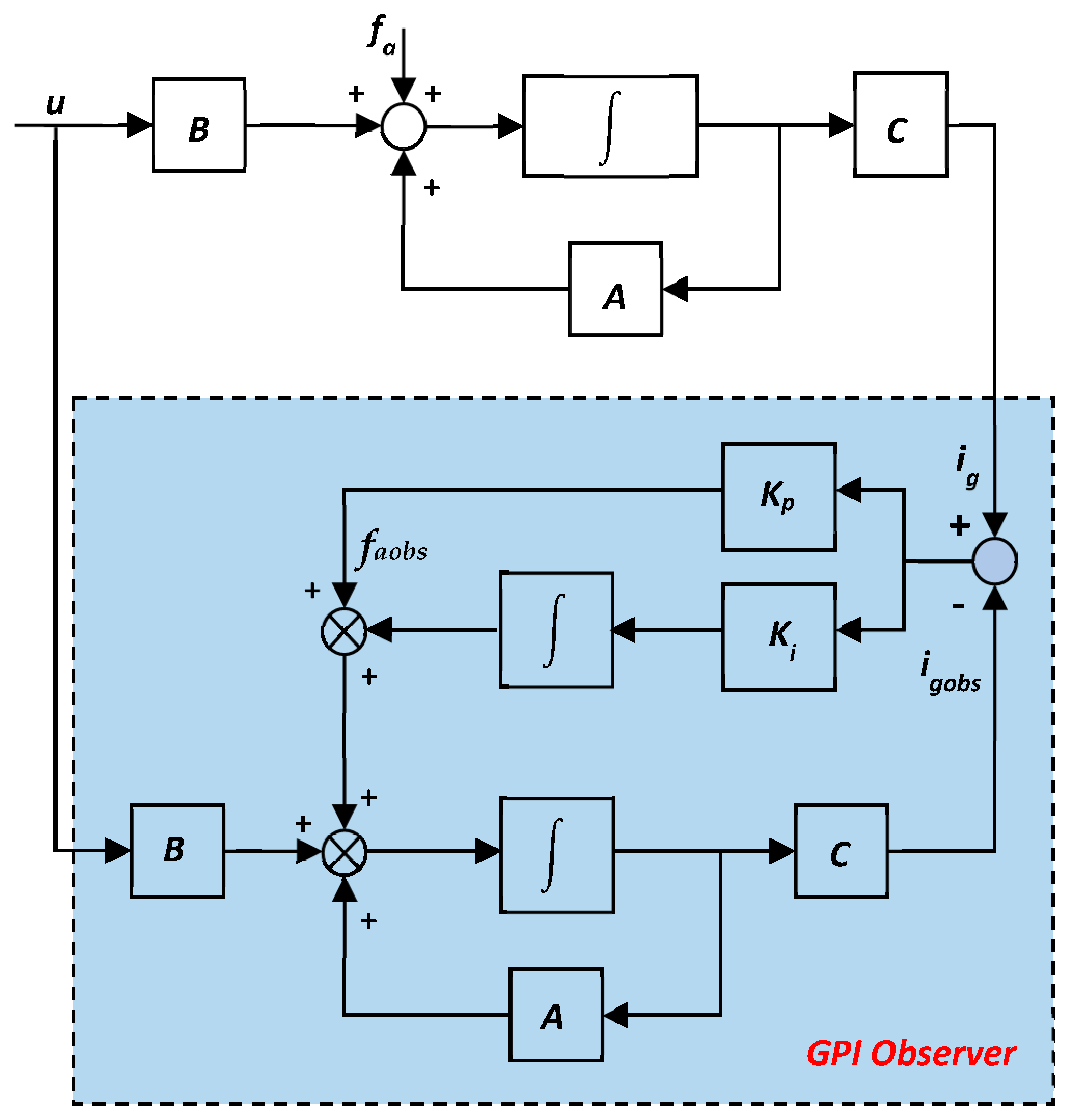
3. Design of GPI and MRAS Observers

In this paper, two generalized proportional integral observers (GPIO) are designed to estimate the grid voltage Vg and the DC-link voltage Vdc, respectively. In the same way, a model reference adaptive system (MRAS) observer is employed to estimate the grid current ig.
From (1), the dynamics of the single-phase PWM rectifier are described by:
d d t i g V d c = R L S 13 L S 13 C 0 i g V d c + 1 L 0 V g + 0 1 C i L y = 1 0 0 1 i g V d c S 13 = S 1 S 3
It can be seen from (2) that the state matrix contains the discrete switching control signal S13. For unipolar sinusoidal PWM, S13 has three possible states during one switching period: ±1 and 0. So, changes in S13 may affect the performance and the convergence of the observer [19,21]. In order to overcome this issue, the switching control signals S1 and S3 may be replaced by their respective duty cycles d1 and d3. During one switching period, the voltage Vab may be expressed as follows:
V a b ( t ) = d 1 d 3 V d c ( t ) = d 13 V d c ( t ) , k T s < t k + 1 T s
Since the switching frequency (10 kHz) is much larger than the grid voltage frequency (50 Hz), then the duty cycle d13 is considered as a constant in one switching period Ts. Finally, d13 is a continuously varying parameter instead of a discrete parameter S13. Furthermore, neglecting high-frequency components, d13 may be considered the fundamental component of S13, and Vab can be expressed as:
V a b ( t ) = m a b V d c sin θ g + φ a b
where mab corresponds to the modulation index, and φab is the phase difference with respect to the grid voltage. Finally, a corresponding equivalent circuit of the grid-side loop of Figure 1 is presented in Figure 2.
The grid current state model is described by:
d i g d t = A i g + B V g V a b
where A = −R/L and B = 1/L.

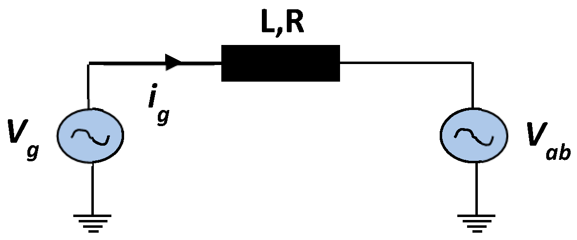
3.1. Grid Voltage GPI Observer Design

In this section, a first GPI observer is designed for observing the grid voltage Vg. Generalized proportional integral observers use not only the estimation error information but also the integral of the estimation error, which makes them useful for the estimation of system disturbances and unknown inputs [41,42].
The structure of the GPIO applied to the grid current state Equation (5) is depicted in Figure 3. The variable fa corresponds to the disturbance and/or unknown input that the GPIO aims to estimate.
In order to analyze the system dynamics, the output of the integrator is extended to a new state variable fa, which denotes the system unknown input and is described by:
f a = V g L
The structure of the GPIO applied to the grid current state Equation (5) is depicted in Figure 3, where the dynamics of the observer are described by:
d d t i g o b s f a o b s = A 1 0 0 i g o b s f a o b s + B 0 u + K p 1 K i 1 i g i g o b s
where Kp1 and Ki1 are the observer’s proportional and integral gains, respectively. The variable faobs is the estimated value of the unknown input fa, and it corresponds to the integral of the estimation error (ig igobs). According to (6) and (7), if the grid voltage is estimated by the GPI observer, u =Vab and then:
f a o b s = V g o b s L

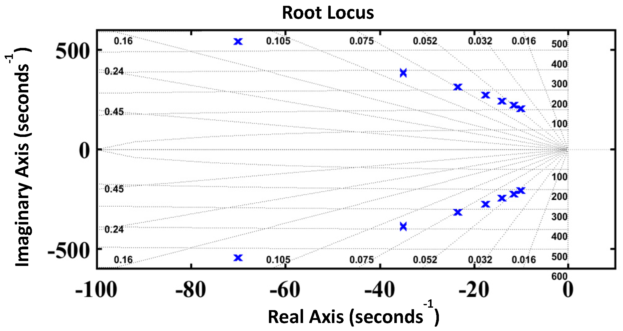
3.2. Observer Stability Analysis

The error model of the proposed observer is obtained for stability analysis, and the estimation errors of the state variables defined in (7) are given by:
e i = i g i g o b s a n d e f = f a f a o b s
Consequently, the state error equation is given by the following [43]:
d d t e i e f = A K p 1 1 K i 1 0 e i e f + 0 d f a d t
From (10), it is observed that the system will be Hurwitz stable if both of the characteristic polynomial’s roots in the matrix Dc, i.e., are in the left half-plane [43].
F 1 ( s ) = s 2 + R L + K p 1 s + K i 1
In order to simplify the design process, we assume that both observer’s poles are located at −w0 and are expressed by:
F 1 ( s ) = s 2 + R L + k p 1 s + k i 1 = s + w 0 2
Therefore:
R L + K p 1 = 2 w 0 and k i 1 = w 0 2
From (12), it is shown that the design of R L + K p 1 and K i 1 is related to the GPI observer’s bandwidth w0. Hence, the key process is the appropriate bandwidth value w0 selection. The observer’s bandwidth is generally selected to be 5–15 times lower than the switching frequency by considering the tradeoff between the fast observation performance and the noise sensitivity immunity [44]. In this paper, the observer bandwidth is selected around 1 kHz, which is 10 times lower than the switching frequency.
In Figure 4, the root locus of the PI observer with grid inductance L as a variable value is shown. It can be seen that the root locus remains on the left side of the s-plan, and the stability of the observer is guaranteed.

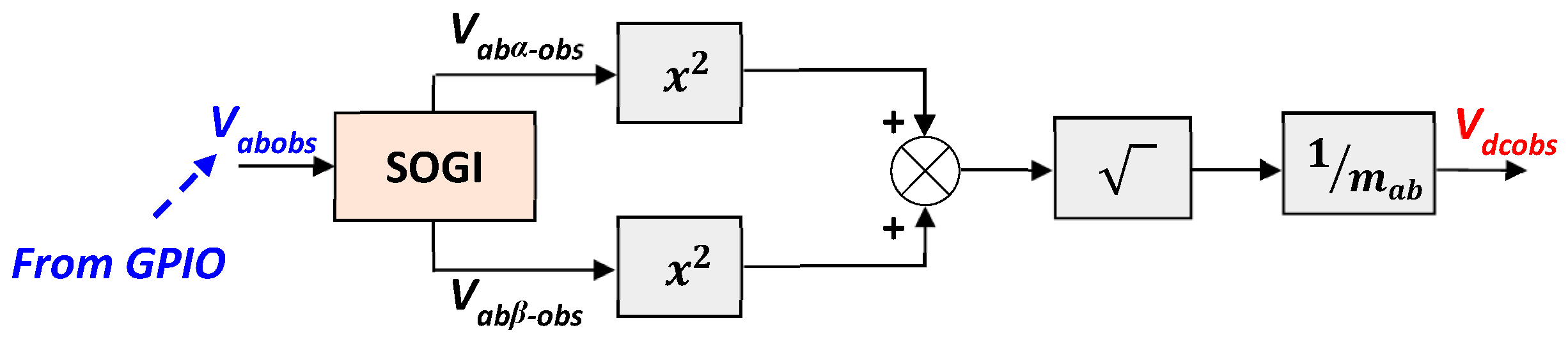
3.3. DC-Link Voltage Estimation Based on SOGI-GPIO

Similarly, a second GPIO is used to estimate the DC-link voltage Vdc. The DC-link voltage estimation is achieved in two steps. First, the fundamental component of the rectifier’s input voltage Vab is estimated through the GPIO. The proposed GPIO structure is similar to the observer used to estimate the grid voltage. Consequently, Vab is considered as an unknown input of the system described by (5) and, therefore, fa =Vab/L. According to (7), if Vab is estimated by the GPI observer, u = Vg, and the estimated unknown input is expressed as:
f a o b s = V a b o b s L
Since the dynamics of the GPIO of Vab are similar to the observer of the grid voltage Vg, then the stability of the observer is guaranteed by the appropriate choice of its proportional and integral parameters Kp2 and Ki2, respectively.
Once the input rectifier voltage is estimated, a SOGI block is used to generate its estimated orthogonal components Vabα-obs and Vabβ-obs of Vabobs, then the estimated value of the DC-link voltage Vdcobs is obtained, as presented in Figure 5.

3.4. Virtual Flux MRAS-Based Grid Current Estimation

The MRAS observer main design concept is based on the use of a reference model and an adaptive model. The idea is to use a correction/adaptation mechanism so that the output of the adaptive model is adjusted to the reference model [45].
Recently, the MRAS observer has been successfully used for grid-connected power converters applications to estimate AC voltages [46] or grid-side impedance parameters [47].
The grid current estimation is based on a grid virtual-flux-based MRAS observer. Its structure is depicted in Figure 6a.
The reference model of the MRAS observer is the virtual flux ΦVg, which can be obtained from the grid voltage measurement. The adaptive model aims to generate the estimated virtual flux value ΦVgobs, expressed as follows:
ϕ V g = V g d t = V a b d t + R i g d t + L i g ϕ V g o b s = V i n * d t + R i g d t + L i g
The estimation errors are given by:
e ϕ = ϕ V g ϕ V g o b s = R s + L i g i g o b s = R s + L e i = F 2 ( s ) e i
The virtual flux estimation error is used to drive a suitable adaptation mechanism which generates the estimated grid current for the adaptive model.
Therefore, a PI corrector is sufficient, and igobs is given by:
i g o b s = k p + k i s e ϕ
Figure 7 shows the root locus of the closed-loop transfer function, presented in Figure 6b, of the MRAS estimator for the grid current with the grid inductance L filter variations. One can clearly deduce the estimator’s stability, since, for all inductance values, the root locus remains on the left side of the s-plan.

4. Proposed Sensor FDI and FTC Strategy

The control strategy of the single-phase PWM rectifier requires accurate and exact measurements of the grid voltage Vg, the grid current ig and the DC-link voltage Vdc. In case of erroneous measurements, the converter’s performance would be seriously perturbed [15]. The overall structure of the proposed multiple-sensor FDI and FTC algorithm is illustrated in Figure 8, while the flowchart of the proposed multiple-sensor fault-tolerant control is depicted in Figure 9. As illustrated by Figure 8a, once the estimated state information is obtained through the GPIOs and MRAS observers, they are compared to the measured information in order to generate the desired residuals. To reduce the impact of the load charge variation and/or system’s parameters’ mismatch on the fault detection process, all residuals are defined as normalized quantities and expressed as:
R V g = V g V g o b s V g n o m , R V d c = V d c V d c o b s V d c * , R i g = i g i g o b s i g n o m
where Vgnom and ignom represent the rated values of Vg and ig, respectively. The detection of the sensor fault is achieved by comparing each residual Rx {x = ig, Vdc, Vg} to a corresponding threshold, Tx {x = ig, Vdc, Vg}. The robustness of the FDI algorithm depends precisely on the residuals’ sensitivity to the system’s parameters and operating point variations. In healthy mode, all residuals should maintain low values (close to zero) below their corresponding thresholds. However, in faulty operating mode, only the residual corresponding to the faulty sensor exceeds its threshold, while all residuals related to healthy sensors remain below their specified thresholds. Hence, the choice of the thresholds should be carefully made taking into account all system variations to minimize false alarms and increase the FDI algorithm robustness while maintaining a fast detection time. Thus, the fault is detected, and the faulty sensor is isolated when the corresponding fault flag Fx{x = ig, Vdc, Vg} is generated:
F x = 1 , if   R x > T x 0 , i f   R x < T x
Once the faulty sensor is identified, the fault-tolerant process is initiated. The faulty measurement is substituted by the estimated one in the feedback control loop. It should be noticed that only two multiple-sensor fault scenarios can be treated: DC-link voltage and grid voltage sensors failure and DC-link voltage and grid current sensors failure. The simultaneous failure of the grid voltage sensor and the grid current sensor cannot be handled by the proposed approach. Figure 8a describes the FDI scheme by the residual generation and their evaluation in order to trigger the FTC process due to the switching value of the faulty sensor flag. Figure 8b presents the fault-tolerant control algorithm in case of Vg and Vdc multiple-sensor faults, whereas Figure 8c describes the FTC algorithm in case of ig and Vdc multiple-sensor faults.

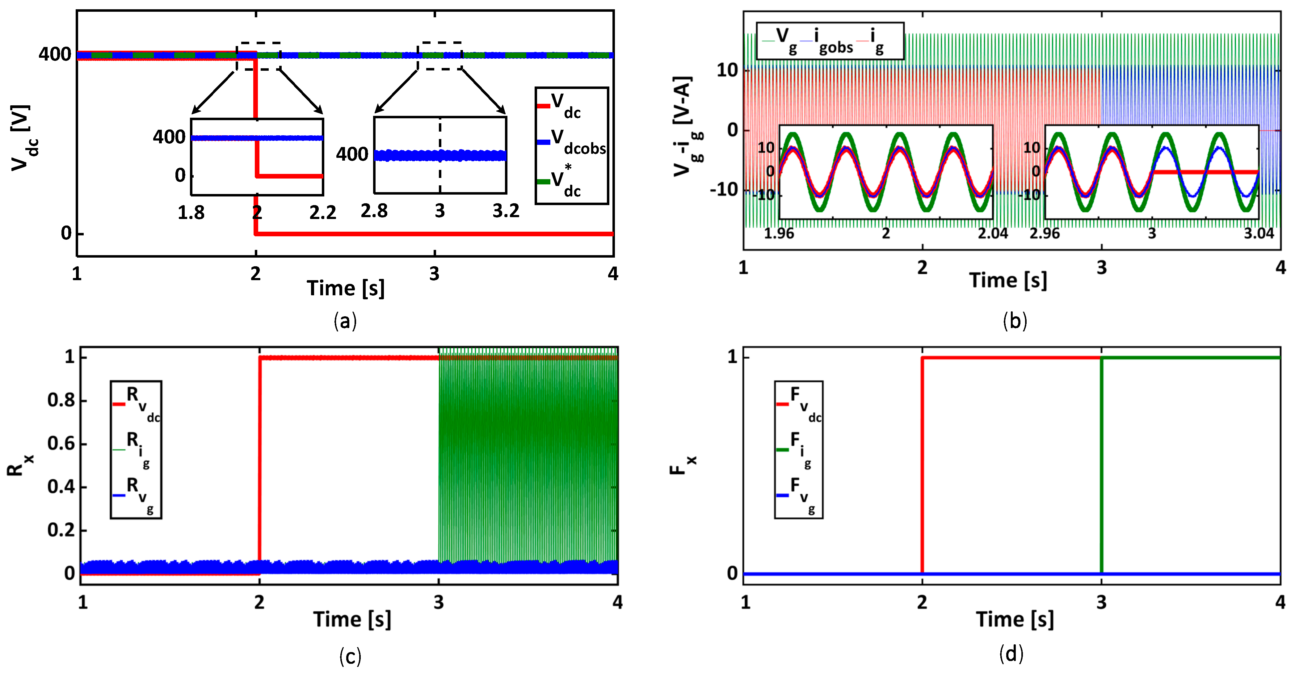
5. Simulation Results

In order to investigate the performance of the proposed FDI and FTC strategy, the single-phase PWM rectifier model is built in the Matlab-Simulink software R2016b environment. The system parameters used for simulation are presented in Table 1.

5.1. Multiple-Sensor Fault-Tolerant Control

The simulation results reported in Figure 10 illustrate the system performance before and after the occurrence of a 100% gain sensor fault of the DC-link voltage sensor at t = 2 s followed by an 80% offset fault of the grid voltage sensor which appears at t = 3 s. In healthy operating mode, i.e., for t < 2 s, all residuals are below the pre-defined fixed thresholds. At the occurrence of the DC-link voltage sensor fault (for t = 2 s), the residual Rvdc exceeds its fixed threshold TVdc, and the fault flag signal FVdc switches from 0 to 1, as presented in Figure 10c,d. This indicates the presence of a DC-link voltage sensor fault. At the same time, both residuals RVg and Rig remain below their respective thresholds TVg and Tig. Once the DC-link voltage sensor fault is correctly located, the faulty measurement is replaced by its estimated value Vdcobs in the converter’s control loop. As presented in Figure 10a,b, Vdcobs follows its reference value, and the grid current ig also follows its reference, in phase with the grid voltage. Similarly, at the occurrence of the grid voltage fault (at time t = 3 s), the residual RVg exceeds its fixed threshold TVg, as shown in Figure 10c,d, and the fault signal FVg switches from 0 to 1. This indicates the presence of a grid voltage sensor fault. Immediately after, the input of the SOGI-PLL block switches from the measured value of the grid voltage to the estimated value Vgobs. After the control reconfiguration, the grid current ig keeps its sinusoidal shape, in phase with the grid voltage Vg, ensuring a unit power factor.
The simulation results depicted in Figure 11 illustrate the system performance before and after the occurrence of a 100% gain fault of the DC-link voltage sensor at t = 2 s followed by a 100% gain fault of the grid current sensor at t = 3 s. At the occurrence of a fault (for t ≥ 2 s), the residual RVdc exceeds its fixed threshold TVdc (Figure 11c), and the fault signal FVdc passes from 0 to 1 (Figure 11d). This indicates the presence of a DC-link voltage sensor fault. At the same time, both residuals Rvg and Rig remain below their thresholds Tig and TVg, the fault signals FVg and Fig remain zero and the faulty measurement is replaced by the estimated value of Vdc. At t = 3 s, residual Rig exceeds its fixed threshold Tig, and the fault signal Fig passes from 0 to 1 (Figure 11d). This indicates the presence of a grid current sensor fault. Once the grid current sensor is correctly located, the faulty measurement is replaced by the estimated value of ig. One can clearly notice that the grid current ig keeps its sinusoidal shape and is in phase with the grid voltage Vg, ensuring a unit power factor (Figure 11b), and the system stability is not affected.

5.2. Post-Fault System Restart with the Single Survivable Sensor

The effectiveness of the proposed FTC approach has been investigated in the previous section by means of simulation. Nevertheless, and since the converter is not continuously working (the converter may be switched off by the user), it is important to investigate the capability of the proposed FTC algorithm to start up the converter using only the single survivable sensor.
Figure 12a–c present the simulation results regarding the start-up of the converter without DC-Link voltage and grid voltage sensors under 50% and 120% variation of nominal values of L and C as well as the operating point variation. As can be seen, all of the observed variables are accurately estimated under different operating conditions. More precisely, when the converter controller is activated, the DC-link estimated voltage reaches its reference value and is equal to the actual DC-link voltage. Moreover, it takes about 40 ms for the estimated grid voltage to reach the actual value. In addition, the resultant grid current presents a highly sinusoidal waveform with a unity power factor operation even with 100% variation of the output load resistance introduced at time t = 1 s (see Figure 12c).
A second test for the start-up of the converter closed-loop operation without DC-link voltage and grid current sensors was performed (Figure 13a–c). It can be observed that the estimated DC-Link voltage follows its reference and actual values. Similarly, the estimated grid current perfectly follows the actual current under L, C and DC load variation. Moreover, the estimated grid voltage follows the actual grid voltage with accuracy even under extreme conditions and parameter uncertainties.
These different case studies prove the robustness of the proposed observation approach considering different operation conditions.

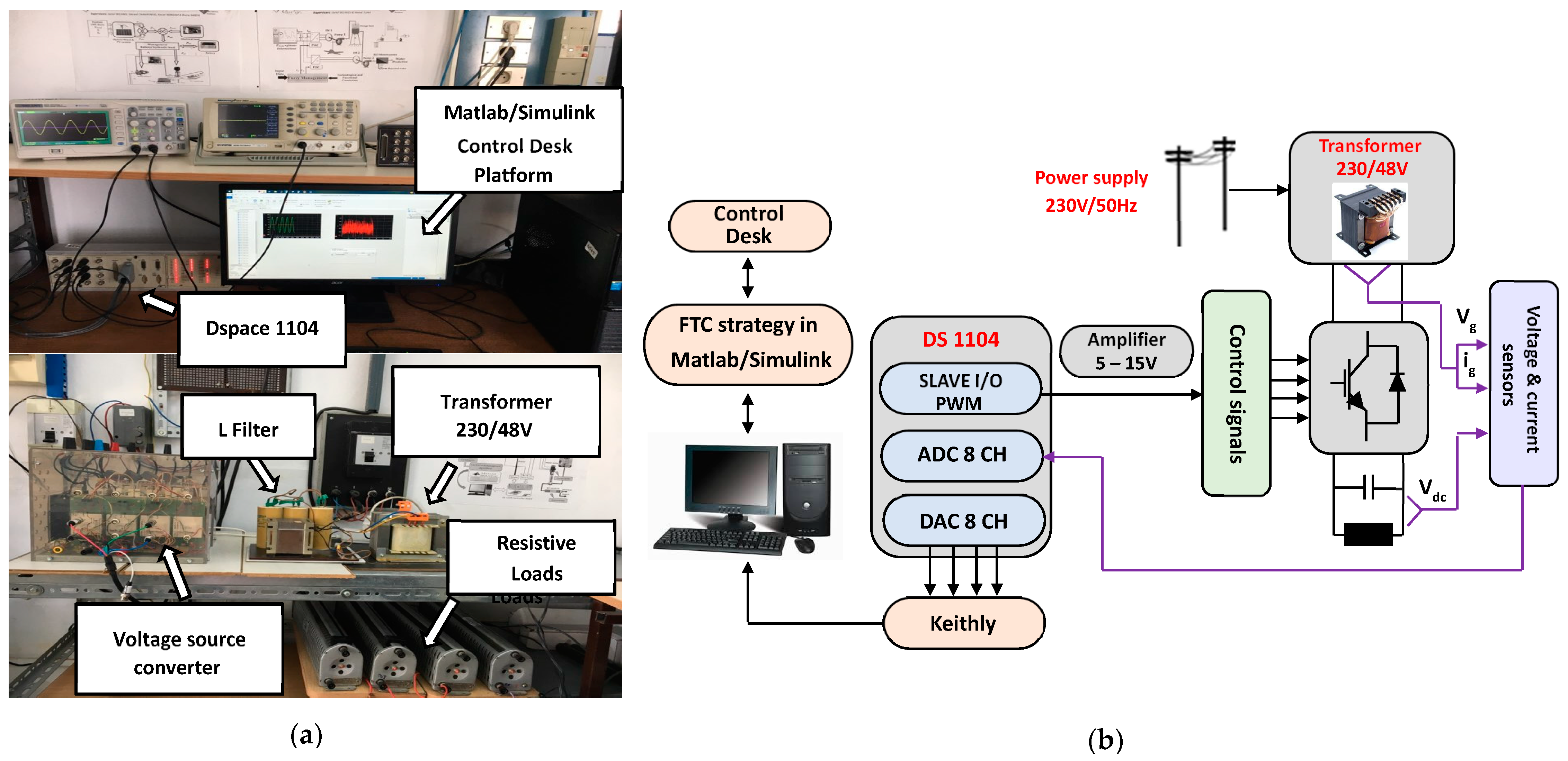
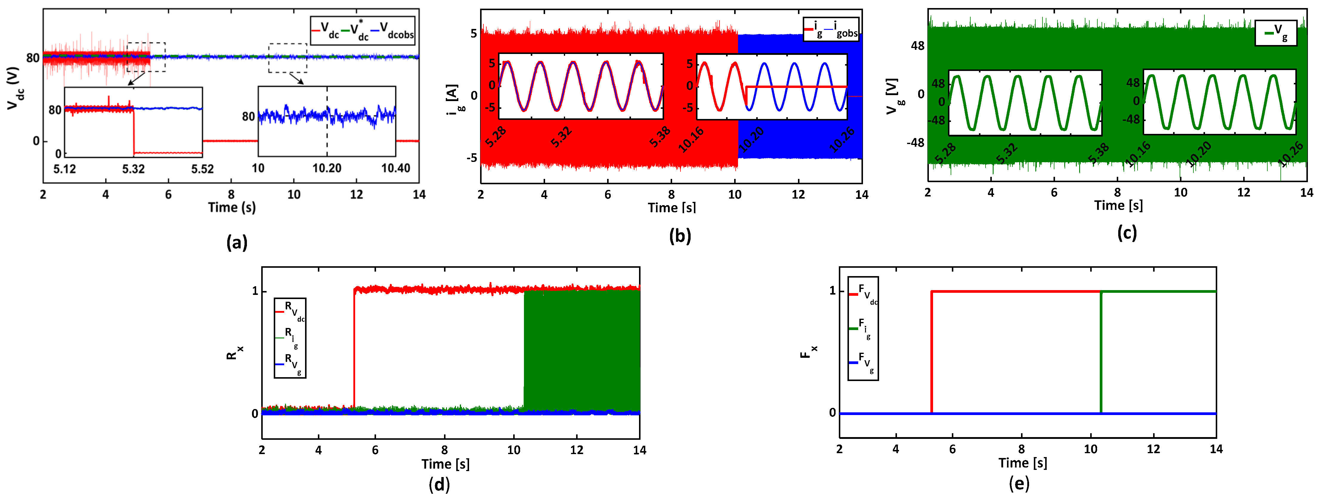
6. Experimental Results

To demonstrate the feasibility and effectiveness of the proposed FTC method, experimental results, based on a reduced-scale experimental setup, are carried out. The structure of the experimental setup is presented in Figure 14. It comprises one Semikron SKiiP voltage source converter used as a single PWM rectifier, an input filter (20 mH, 0.2 Ω), a DC-bus capacitor bank of 1100 µF and a variable resistive load. The rectifier’s PWM frequency is set to 10 kHz. A current sensor (LEM PR 30) is used to measure the grid current ig. The DC-link voltage and the grid voltage are measured by two Tektronix p5200 voltage sensors. A 48 V/230 V single-phase transformer is used for the converter’s grid connection. The FTC algorithm is implemented through the Matlab-Simulink environment into the dSPACE DS1104 digital controller board using a sampling time of 100 µs. All experimental setup parameters are reported in Table 2. The values of the different proportional and integral observers’ gains Kp and Ki used in simulations and experiments are listed in Table 3.

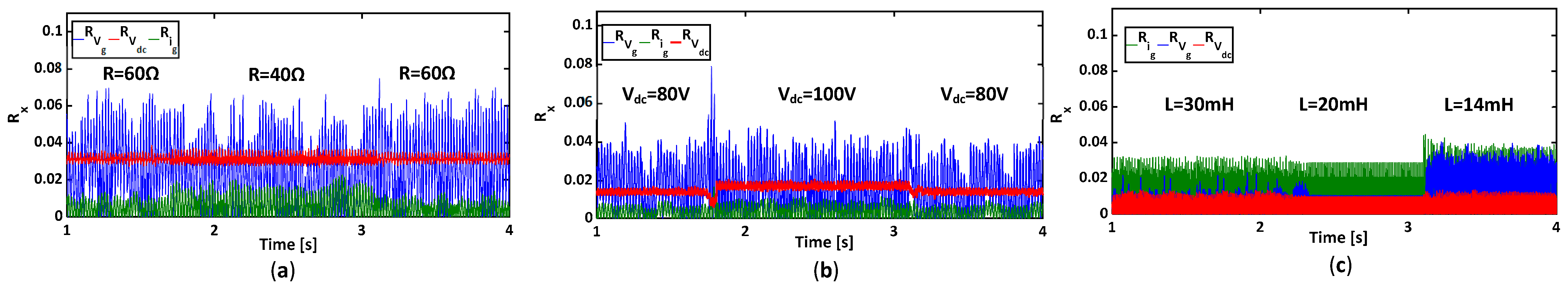
6.1. Residual Robustness Analysis and Threshold Selection

The robustness of the FDI algorithm under healthy operation depends on the residuals’ sensitivity to the system parameters’ variations and to the operating point variations. In Figure 15a, the experimental results regarding the variations of the three residuals under load variations are reported. The load resistance is shifted from 60 to 40 Ω at time t = 1.70 s and again from 40 to 60 Ω at time t = 3.10 s. It can be seen that during resistance load variations, all residuals maintain low values below 0.08. In Figure 15b, the residuals’ evolution under a DC-link voltage variation from 80 V to 100 V is detailed. All residuals present small variations, always below 0.08. Finally, the sensitivity of the proposed fault diagnosis approach is tested under a system parameter variation, namely the L filter inductance variation. The filter inductance was first changed from 30 mH to 20 mH and then to 14 mH. As can be seen, slight variations of the three residuals occurred; however, such variations are still low, around 0.05.
Therefore, the behavior of the three residuals following these different tests showed that their oscillations are still very small, close to zero. The thresholds should be carefully selected in order to guarantee the proposed method high immunity under healthy operation, as well as an accurate/fast detection and localization of the faulty sensor [15]. As presented in Figure 15, the defined fault detection residuals variations under healthy operation are small and always below 0.08. Under faulty operation mode, the variations of the residuals correspond to the measurement error. According to this, thresholds TVdc, TVg and Tig may have the same value, fixed at 0.1.

6.2. Multiple-Sensor Fault-Tolerant Control

The experimental results shown in Figure 16 present the performance of the proposed FDI and FTC in the case of DC-link voltage and grid voltage sensor faults. At time t = 3.90 s, the DC-link voltage fault is introduced (Figure 16a). In healthy operation mode, Vdc = 80 V; thus, the output of the DC-link voltage sensor value is set to 0. While grid voltage and current residuals remain at small values below their respective thresholds, the DC-link voltage Rvdc exceeds its threshold Tvdc. The fault flag Fvdc is set to 1, which indicates that the Vdc sensor is faulty. Immediately, the fault tolerance process is triggered, and the virtual sensor Vdcobs is sent to the control loop of the system. Then, an 80% offset fault of the grid voltage sensor is applied at time t = 10.05 s, as illustrated in Figure 16b. As a result, the grid voltage residual exceeds its threshold, and its corresponding fault flag is then set to 1 (Figure 16d,e). Furthermore, when the grid voltage sensor’s detection is achieved, the input of the SOGI-PLL block switches from the measured grid voltage to the estimated grid voltage obtained from the GPIO. Now, the converter’s control loop is employing only the single survivable grid current sensor. The DC−link voltage control loop, as well as the grid current reference generation, are based on the estimated voltages values Vdcobs and Vgobs, respectively. The single-phase PWM rectifier can still operate normally after the DC-link and grid voltage sensors malfunction. It can be seen in the zoomed parts of Figure 16a–c that the DC-link voltage is well regulated at 80 V, the grid current is sinusoidal with low harmonic distortion and the grid power factor is equal to 1.
The experimental results concerning the control reconfiguration for the single-phase converter in case of 100% gain fault of the grid current sensor fault and 100% gain fault of the DC−link voltage sensor are detailed in Figure 17. When the DC−link voltage sensor fault is introduced at time t = 5.32 s, the residual Rvdc exceeds its fixed threshold Tvdc, and therefore, the fault flag Fvdc is equal to 1. Consequently, Vdcest substitutes the erroneous measurement in the loop control. It can be seen from Figure 17a–c that the DC−link voltage sensor fault tolerance is successfully achieved, and the system maintains its performance. At time t = 10.193 s, the output of the grid current sensor is forced to 0. As a consequence, as indicated in Figure 17d, the grid current residual exceeds its threshold, and the fault flag Fig is set to 1. Once the grid current sensor is correctly located, the faulty measurement is replaced by the estimated value of igobs. After the control reconfiguration of the grid current sensor fault, only the grid voltage sensor survives. The zooms of Figure 17a–c clearly show that Vdcobs and igobs are following their respective reference values, ensuring a unit power factor, and that the converter stability is not affected.

6.3. Post-Fault System Restart with the Single Survivable Sensor

Figure 18 presents the experimental results in the case of DC−link and grid voltages sensorless operation of the converter. Hence, the rectifier’s control loop is only driven by the grid current sensor. Initially, the converter is operating as a diode full bridge. At time t = 1.88 s, the feedback control is activated. Figure 18a shows the variation of the observed quantity Vdcobs and of the actual voltage Vdc. It can be seen that the observed DC−link voltage, as well as the actual DC−link voltage, are correctly reaching their reference value. Figure 18b,c show the variations of the estimated grid voltage Vgobs, the actual grid voltage Vg and the grid current ig. The estimated grid voltage follows the measured one, and the grid current ig has a sinusoidal waveform in phase with the grid voltage. Moreover, at time t = 8.25 s, the load is changed from 100 Ω to 36 Ω. It can be observed that the proposed control strategy keeps its good performance. The estimated values Vdcobs and Vgobs are following their respective actual values while ensuring a unit power factor, and the converter stability is not affected.
The start-up of the PWM rectifier operation without DC−link voltage and grid current sensors is illustrated in Figure 19. The closed-loop control is initiated at time t = 4.25 s. Similarly to the simulation results, the observed voltage Vdcobs and the actual voltage Vdc are correctly reaching their reference value. As shown in Figure 19c, the estimated grid current igobs is following the actual grid current ig.
Moreover, the grid unity power factor is guaranteed according to Figure 19b,c, where the grid current is in phase with the grid voltage. At t = 8.89 s, the load is changed from 100 Ω to 40 Ω. It can be observed from Figure 19a that the proposed control strategy keeps its good performance. The estimated values Vdcobs and igobs are following their respective reference values while ensuring a unit power factor, and the converter stability is not affected.

6.4. Comparative Study with Previously Proposed Methods

To better highlight the benefits of the proposed multiple-sensor fault diagnosis algorithm, its performance is compared with some previously reported approaches, as summarized in Table 4. It can be seen that the proposed approach has similar sensor fault detection and sensor FTC performance to those discussed by [15,17,21,25,30]. Nevertheless, the abovementioned methods cannot handle multiple-sensor failures. Moreover, they need the use of an additional DC load current sensor [15,25,30], which increases the system’s cost.
The approach presented by [27] ensures a multiple-sensor fault-tolerant control for a three-phase grid-connected inverter fed by PV arrays. It has focused on the three grid-side AC current sensor faults and DC-link voltage sensor faults. The proposed sensor fault detection and isolation decision logic can guarantee the detection of a single- or multiple-AC-sensor fault; however, if the DC-link voltage sensor is faulty, it violates one or more analytical redundancy relations on the AC side. In order to overcome this issue, when both AC and DC sensor faults occur, the isolation high priority is given to the DC sensor, while the AC sensors are given low-priority fault isolation signals.
In the proposed FTC approach, it has been shown that an AC sensor fault can be discriminated from a DC sensor fault without any constraints. When DC and AC sensor faults occur, the proposed FTC method can easily handle both of them.
The method discussed by [19] ensures multiple-sensor fault-tolerant control in cascaded H-bridge multilevel converters and can identify the fault type (open-circuit fault, stuck fault, gain fault, offset fault, and abnormal noise). However, only one multiple-sensor FTC scenario has been discussed, which involves the grid current sensor and the DC-link voltage sensor. In our work, two scenarios have been presented: in the first scenario, a DC-link voltage sensor fault followed by a grid voltage sensor and, in the second scenario, a DC-link voltage sensor fault followed by a grid current sensor fault. It is important to highlight that for the multiple-grid current sensor and DC-link voltage sensor faults, the extreme case with 100% gain faults for both sensors has been discussed.
Both work in [19,27] and our work address multiple-sensor faults, but the proposed work emphasizes a novel approach that simplifies the system by not requiring additional sensors, which represents an improvement in terms of system complexity and cost.
Finally, none of these methods has proposed a unified sensor fault detection approach for the main three sensors used in the closed-loop control of the single-phase PWM rectifier without any extra hardware. The extensive experimental results demonstrated that the proposed method can be easily implemented into a real-time digital controller, which may improve the cost and the performance of a single-phase PWM converter in several industrial applications such as EVs, electric traction systems, and so on.
Likewise, the proposed method has some limitations. It cannot identify the sensor fault type (scaling, offset, open-circuit, and so on). Additional features should be extracted in order to enhance its performance in that sense. Moreover, open-circuit faults would change the rectifier’s input voltage, which results in high estimation errors and may lead to a sensor false alarm. Hence, in future work, an effective algorithm that can diagnose and discriminate sensor faults from power semiconductor faults in a single-phase PWM converter will be considered.

7. Conclusions

This paper proposes a novel, simple, and fast unified sensor fault detection and isolation without extra hardware and sensor fault-tolerant control of a single-phase pulse PWM rectifier based on residual generation through a robust bank of GPI and MRAS observers. Compared with the previous published methods, the proposed approach offers some benefits:
(1)
The proposed approach is a unified sensor fault detection method for the main three sensors used in the closed-loop control of the single-phase PWM rectifier without any extra hardware.
(2)
In addition to single-sensor fault detection, the proposed approach is able to diagnose multiple-sensor faults and ensure a post-fault operation of the PWM rectifier with the single survivable sensor.
(3)
It has the capability to guarantee the start-up of the single-phase PWM rectifier with a single survivable sensor and with the same performance as in healthy operation, even under DC-link load variations or system’s parameters’ mismatch.
In particular, if compared with other methods addressing multiple-sensor faults, the proposed method relies on a novel approach that does not require additional sensors, with a moderate mathematical complexity, based on a clear mechanism for fault detection and isolation. Additionally, it is characterized by robustness and practical viability, which are important features in real-world applications.
Several simulations and experimental results have been discussed to demonstrate the robustness and effectiveness of the proposed approach under distinct simultaneous faulty scenarios and to show the very good performance of the post-fault operation of the single-phase PWM rectifier in terms of DC-link voltage regulation and grid-side power quality.
In future work, some improvements to the proposed method should be introduced in order to identify the sensor fault type and to discriminate sensor faults from power semiconductor faults. In this way, the combination of model-based approaches with data-driven approaches is of great benefit.

Author Contributions

Conceptualization, M.D. and S.K.E.K.; methodology, M.D. and S.K.E.K.; software, M.D. and M.S.; validation, M.D., M.S. and S.K.E.K.; formal analysis, S.K.E.K., C.B. and K.J.; investigation, M.D. and S.K.E.K.; resources, M.D. and M.S.; writing—original draft preparation, M.D., M.S. and S.K.E.K.; writing—review and editing, S.K.E.K., C.B. and K.J.; supervision, S.K.E.K., C.B. and K.J.; project administration, S.K.E.K., C.B. and K.J. All authors have read and agreed to the published version of the manuscript.

Funding

This work was supported by the Tunisian Ministry of Higher Education and Scientific Research (MHESR) and the department of Astronautics, Electrical and Energetic Engineering, Sapienza University of Rome, Italy.

Data Availability Statement

Data are contained within the article.

Conflicts of Interest

The authors declare no conflicts of interest.

Nomenclature

ADCAnalogue to Digital Converter
CDC-link capacitor
d1, d3Duty Cycle
DACDigital to Analogue Converter
DSOGIDual Second-Order Generalized Integrator
EVsElectric Vehicles
faDisturbance and/or unknown input
faobsObserved value of the disturbance and/or unknown input
FDIFault Detection and Isolation
FEFault Estimation
FTCFault-Tolerant Control
fswSwitching frequency
FxFault Flag, x = {ig, Vg, Vdc}
GPIOGeneralized Proportional Integral Observer
icCurrent in the DC-side capacitor
idcDC-side output current
igGrid current
igobsObserved value of the grid current
ig*Reference value of the grid current
ignomNominal value of the grid current
iLLoad current
TfGrid current fundamental period
KiIntegral Gain
KpProportional Gain
LLine inductance
LOLuenberger observer
mabModulation index
MRASModel Reference Adaptive System
PIProportional Integral
PRProportional Resonant
PWMPulse-Width Modulated
RLine resistance
RLRated Load resistance
RxResidual, x = {ig, Vg, Vdc}
SMOSliding-Mode Observer
SOGISecond-Order Generalized Integrator
SOGI-PLLSecond-Order Generalized Integrator Phase-Locked Loop
S1, S3Binary Switching Control Signal
TsSampling Time
TxThreshold, x = {ig, Vg, Vdc}
VabRectifier input voltage
VabobsEstimated value of the rectifier input voltage
Vabobsα, VabobsβEstimated orthogonal components of the rectifier input voltage
VdcDC-link voltage
Vdc*Reference value of the DC-link voltage
VdcobsObserved value of the DC-link voltage
Vin*Reference value of the rectifier voltage
VgGrid voltage
VgnomNominal value of the grid voltage
VgobsObserved value of the grid voltage
θgPhase angle
ϕgGrid virtual flux
ϕgobsObserved value of the grid virtual flux
φabPhase difference

References

  1. Ndabarushimana, E.; Qin, N.; Ma, L. Disturbance Decoupling for a Single-Phase Pulse Width Modulation Rectifier Based on an Extended H-Infinity Filter. Electronics 2023, 12, 2765. [Google Scholar] [CrossRef]
  2. Zhu, Y.; Wang, Z.; Wang, C.; Zhu, Y.; Cao, X. A Novel Improved Coordinate Rotated Algorithm for PWM Rectifier THD Reduction. Electronics 2022, 11, 1435. [Google Scholar] [CrossRef]
  3. Kang, L.; Zhang, J.; Zhou, H.; Zhao, Z.; Duan, X. Model predictive current control with fixed switching frequency and dead-time compensation for single-phase PWM rectifier. Electronics 2021, 10, 426. [Google Scholar] [CrossRef]
  4. Bi, Y.; Wu, C.; Zhao, T.; Li, H.; Xu, J.; Shu, G.; Wang, Y. Modified deadbeat predictive current control method for single-phase AC–DC PFC converter in EV charging system. IEEE Trans. Ind. Electron. 2023, 70, 286–297. [Google Scholar] [CrossRef]
  5. Ramos, L.A.; Van Kan, R.F.; Mezaroba, M.; Batschauer, A.L. A Control Strategy to Smooth Power Ripple of a Single-Stage Bidirectional and Isolated AC-DC Converter for Electric Vehicles Chargers. Electronics 2022, 11, 650. [Google Scholar] [CrossRef]
  6. Yang, C.; Wang, J.; Wang, C.; You, X.; Yu, S.; Su, P. Tuning method of resonant current controller with DC elimination for PWM rectifiers in electric multiple units. IEEE Trans. Transp. Electrif. 2020, 6, 740–751. [Google Scholar] [CrossRef]
  7. Tasiu, I.A.; Liu, Z.; Wu, S.; Yu, W.; Al-Barashi, M.; Ojo, J.O. Review of recent control strategies for the traction converters in high-speed train. IEEE Trans. Transp. Electrif. 2022, 8, 2311–2333. [Google Scholar] [CrossRef]
  8. Liu, H.; Ma, L.; Peng, L.; Song, W.; Cheng, S. Robust current control scheme for single-phase PWM rectifiers based on improved μ-synthesis in electric locomotive. IET Power Electron. 2020, 13, 4068–4078. [Google Scholar] [CrossRef]
  9. Peng, L.; Ma, L.; Song, W.; Liu, H. A simple model predictive instantaneous current control for single-phase PWM converters in stationary reference frame. IEEE Trans. Power Electron. 2022, 37, 7629–7639. [Google Scholar] [CrossRef]
  10. Lee, G.-Y.; Park, H.-C.; Ji, M.-W.; Kim, R.-Y. Digitalized Control Algorithm of Bridgeless Totem-Pole PFC with a Simple Control Structure Based on the Phase Angle. Electronics 2023, 12, 4449. [Google Scholar] [CrossRef]
  11. Deng, Q.; Gou, B.; Ge, X.; Lin, C.; Xie, D.; Feng, X. A High-accuracy-light-AI Data-driven Diagnosis Method for Open-circuit Faults in Single-Phase PWM Rectifiers. IEEE Trans. Transp. Electrif. 2023, 9, 4352–4365. [Google Scholar] [CrossRef]
  12. Qin, N.; Wang, T.; Huang, D.; You, Y.; Zhang, Y. VWM-DCRNN: A Method of Combining Signal Processing With Deep Learning for Fault Diagnosis in Single-Phase PWM Rectifier. IEEE Trans. Power Electron. 2023, 38, 8894–8906. [Google Scholar] [CrossRef]
  13. Zhang, K.; Gou, B.; Feng, X. Online Fault Diagnosis for Single-Phase PWM Rectifier Using Data-Driven Method. CPSS Trans. Power Electron. Appl. 2022, 7, 49–57. [Google Scholar] [CrossRef]
  14. Li, Z.; Wang, B.; Ren, Y.; Wang, J.; Bai, Z.; Ma, H. L- and LCL-Filtered Grid-Tied Single-Phase Inverter Transistor Open-Circuit Fault Diagnosis Based on Post-Fault Reconfiguration Algorithms. IEEE Trans Power Electron. 2019, 34, 10180–10192. [Google Scholar] [CrossRef]
  15. Youssef, A.B.; El Khil, S.K.; Slama-Belkhodja, I. State Observer-Based Sensor Fault Detection and Isolation, and Fault Tolerant Control of a Single-Phase PWM Rectifier for Electric Railway Traction. IEEE Trans Power Electron. 2013, 28, 5842–5853. [Google Scholar] [CrossRef]
  16. Poon, J.; Jain, P.; Konstantakopoulos, I.C.; Spanos, C.; Panda, S.K.; Sanders, S.R. Model-Based Fault Detection and Identification for Switching Power Converters. IEEE Trans Power Electron. 2017, 32, 1419–1430. [Google Scholar] [CrossRef]
  17. Yu, Y.; Song, Y.; Tao, H.; Hu, J. Voltage and Current Sensor Fault Diagnosis Method for Traction Rectifier in High-Speed Trains. Electronics 2024, 13, 197. [Google Scholar] [CrossRef]
  18. Ndrabarushimana, E.; Ma, L. Robust Sensor Fault Detection for a Single-Phase Pulse Width Modulation Rectifier. Electronics 2023, 12, 2366. [Google Scholar] [CrossRef]
  19. Xie, D.; Lin, C.; Zhang, Y.; Sangwongwanich, A.; Ge, X.; Feng, X.; Wang, H. Diagnosis and Resilient Control for Multiple Sensor Faults in Cascaded H-Bridge Multilevel Converters. IEEE Trans. Power Electron. 2023, 38, 11435–11450. [Google Scholar] [CrossRef]
  20. Xia, J.; Guo, Y.; Dai, B.; Zhang, X. Sensor Fault Diagnosis and System Reconfiguration Approach for an Electric Traction PWM Rectifier Based on Sliding Mode Observer. IEEE Trans Ind. Appl. 2017, 53, 4768–4778. [Google Scholar] [CrossRef]
  21. Xia, J.; Li, Z.; Gao, X.; Guo, Y.; Zhang, X. Real-time sensor fault identification and remediation for single-phase grid-connected converters using hybrid observers with unknown input adaptation. IEEE Trans. Ind. Electron. 2023, 70, 2407–2418. [Google Scholar] [CrossRef]
  22. Zhang, K.; Jiang, B.; Yan, X.-G.; Mao, Z. Incipient Voltage Sensor Fault Isolation for Rectifier in Railway Electrical Traction Systems. IEEE Trans Ind. Electron. 2017, 64, 6763–6774. [Google Scholar] [CrossRef]
  23. Zhang, K.; Jiang, B.; Yan, X.-G.; Shen, J. Interval Sliding Mode Observer Based Incipient Sensor Fault Detection with Application to a Traction Device in China Railway High-Speed. IEEE Trans Veh. Technol. 2019, 68, 2585–2597. [Google Scholar] [CrossRef]
  24. Xiong, J.; Zhang, J.; Xu, Z.; Din, Z.; Zheng, Y. Active power decoupling control for PWM converter considering sensor failures. IEEE J. Emerg. Sel. Top. Power Electron. 2023, 11, 2236–2245. [Google Scholar] [CrossRef]
  25. Chowdhury, V.R.; Kimball, J.W. Robust Control Scheme for a Three Phase Grid-Tied Inverter with LCL Filter During Sensor Failures. IEEE Trans Ind. Electron. 2021, 68, 8253–8264. [Google Scholar] [CrossRef]
  26. Merai, M.; Naouar, M.W.; Slama-Belkhodja, I.; Monmasson, E. FPGA-Based Fault-Tolerant Space Vector-Hysteresis Current Control for Three-Phase Grid-Connected Converter. IEEE Trans Ind. Electron. 2016, 63, 7008–7017. [Google Scholar] [CrossRef]
  27. Mehmood, F.; Papadopoulos, P.M.; Hadjidemetriou, L.; Charalambous, A.; Polycarpou, M.M. Model-based fault diagnosis scheme for current and voltage sensors in grid side converters. IEEE Trans. Power Electron. 2023, 38, 5360–5375. [Google Scholar] [CrossRef]
  28. Ben Youssef, A.; El Khil, S.K.; Belkhodja, I.S. Open-circuit fault diagnosis and voltage sensor fault tolerant control of a single phase pulsed width modulated rectifier. Math. Comput. Simul. 2017, 131, 234–252. [Google Scholar] [CrossRef]
  29. Xia, Y.; Gou, B.; Xu, Y. Current sensor fault diagnosis and fault tolerant control for single-phase PWM rectifier based on a hybrid model-based and data driven method. IET Power Electron. 2020, 13, 4150–4157. [Google Scholar] [CrossRef]
  30. Gong, Z.; Huang, D.; Jadoon, H.U.K.; Ma, L.; Song, W. Sensor-Fault-Estimation-Based Tolerant Control for Single-Phase Two-Level PWM Rectifier in Electric Traction System. IEEE Trans Power Electron. 2020, 35, 12274–12284. [Google Scholar] [CrossRef]
  31. Dardouri, M.; El Khil, S.K.; Jelassi, K. Current Sensor Fault Reconstruction and Compensation of an AC-Voltage Sensorless Controlled Single Phase Grid Connected Converter using PI-Observers. Int. J. Renew. Energy Res. (IJRER) 2022, 12, 248–258. [Google Scholar]
  32. Gong, Z.; Huang, D.; Ma, L.; Qin, N.; Jadoon, H.U.K. Grid voltage sensor fault-tolerant control for single-phase two-level PWM rectifier. IET Electr. Power Appl. 2021, 16, 776–788. [Google Scholar] [CrossRef]
  33. Chen, Z.; Chen, W.; Fan, X.; Peng, T.; Yang, C. JITL-MBN: A realtime causality representation learning for sensor fault diagnosis of traction drive system in high-speed trains. IEEE Trans. Neural Netw. Learn. Syst. 2022. early access. [Google Scholar] [CrossRef] [PubMed]
  34. Ni, Q.; Zhan, Z.; Li, X.; Zhao, Z.; Lai, L.L. A Real-time Fault Diagnosis Method for Grid-Side Overcurrent in Train Traction System using Signal Time Series Feature Pattern Recognition. IEEE Trans. Ind. Electron. 2023, 71, 4210–4218. [Google Scholar] [CrossRef]
  35. Zhu, Y.; Tang, H. Automatic damage detection and diagnosis for hydraulic structures using drones and artificial intelligence techniques. Remote Sens. 2023, 15, 615. [Google Scholar] [CrossRef]
  36. Zhu, Y.; Xie, M.; Zhang, K.; Li, Z. A Dam Deformation Residual Correction Method for High Arch Dams Using Phase Space Reconstruction and an Optimized Long Short-Term Memory Network. Mathematics 2023, 11, 2010. [Google Scholar] [CrossRef]
  37. Gao, Z.; Cecati, C.; Ding, S.X. A survey of fault diagnosis and fault-tolerant techniques—Part I: Fault diagnosis with model-based and signal-based approaches. IEEE Trans. Ind. Electron. 2015, 62, 3757–3767. [Google Scholar] [CrossRef]
  38. Chakraborty, C.; Verma, V. Speed and Current Sensor Fault Detection and Isolation Technique for Induction Motor Drive Using Axes Transformation. IEEE Trans. Ind. Electron. 2015, 62, 1943–1954. [Google Scholar] [CrossRef]
  39. Kommuri, S.K.; Bin Lee, S.; Veluvolu, K.C. Robust Sensors-Fault-Tolerance with Sliding Mode Estimation and Control for PMSM Drives. IEEE/ASME Trans. Mechatron. 2018, 23, 17–28. [Google Scholar] [CrossRef]
  40. Han, Y.; Luo, M.; Zhao, X.; Guerrero, J.M.; Xu, L. Comparative Performance Evaluation of Orthogonal-Signal-Generators-Based Single-Phase PLL Algorithms—A Survey. IEEE Trans. Power Electron. 2016, 31, 3932–3944. [Google Scholar] [CrossRef]
  41. Xu, J.; Mi, C.C.; Cao, B.; Deng, J.; Chen, Z.; Li, S. The State of Charge Estimation of Lithium-Ion Batteries Based on a Proportional-Integral Observer. IEEE Tans Veh. Technol. 2014, 63, 1614–1621. [Google Scholar]
  42. Lu, J.; Savaghebi, M.; Ghias, A.M.Y.M.; Hou, X.; Guerrero, J.M. A reduced-order generalized proportional integral observer-based resonant super-twisting sliding mode control for grid-connected power converters. IEEE Trans. Ind. Electron. 2020, 68, 5897–5908. [Google Scholar] [CrossRef]
  43. Söffker, D.; Yu, T.-J.; Müller, C. State estimation of dynamical systems with nonlinearities by using proportional-integral observer. Int. J. Syst. Sci. 1995, 26, 1571–1582. [Google Scholar] [CrossRef]
  44. Qi, Y.; Zafarani, M.; Gurusamy, V.; Akin, B. Advanced severity monitoring of interturn short circuit faults in PMSMs. IEEE Trans. Transp. Electrif. 2019, 5, 395–404. [Google Scholar] [CrossRef]
  45. Mukherjee, S.; Chowdhury, V.R.; Shamsi, P.; Ferdowsi, M. Grid Voltage Estimation and Current Control of a Single-Phase Grid-Connected Converter Without Grid Voltage Sensor. IEEE Trans Power Electron. 2018, 33, 4407–4418. [Google Scholar] [CrossRef]
  46. Dardouri, M.; El Khil, S.K.; Jelassi, K. Sensorless Active Damping of LCL_Filter based on MRAS Estimator for Single-Phase Grid-Connected Inverter. In Proceedings of the 2019 10th International Renewable Energy Congress (IREC), Sousse, Tunisia, 26–28 March 2019; pp. 1–5. [Google Scholar]
  47. Mehreganfar, M.; Saeedinia, M.H.; Davari, S.A.; Garcia, C.; Rodriguez, J. Sensorless Predictive Control of AFE Rectifier with Robust Adaptive Inductance Estimation. IEEE Trans Ind. Inform. 2019, 15, 3420–3431. [Google Scholar] [CrossRef]
Figure 1. Single-phase PWM rectifier: Converter Topology and its multiloop control scheme.
Electronics 13 00502 g001
Figure 2. Equivalent Structure of the single-phase PWM rectifier.
Electronics 13 00502 g002
Figure 3. Structure of the GPI Observer.
Electronics 13 00502 g003
Figure 4. Root locus plot of the grid voltage GPIO with L as a variable value.
Electronics 13 00502 g004
Figure 5. Structure of the SOGI-based DC-Link voltage estimator.
Electronics 13 00502 g005
Figure 6. MRAS-based estimator: (a) MRAS-based grid current estimator’s structure; (b) Equivalent block diagram of the MRAS estimator.
Electronics 13 00502 g006
Figure 7. Root locus plot of the grid current MRAS estimator with L as a variable value.
Electronics 13 00502 g007
Figure 8. Structure of the proposed multiple-sensor faults FDI and FTC approach: (a) FDI general structure; (b) FTC for case 1: DC-link voltage and grid voltage sensors failure; (c) FTC for case 2: DC-link voltage and grid current sensor failure.
Electronics 13 00502 g008
Figure 9. Flowchart of the proposed single- and multiple-sensor fault detection and FTC.
Electronics 13 00502 g009
Figure 10. Simulation results for control reconfiguration in case of 100% gain fault of the DC−link voltage sensor and 80% offset fault of the grid voltage sensor, (a) Vdc fault tolerant control, (b) Vg fault tolerant control, (c) Residuals evolution, (d) Fault flags variations.
Electronics 13 00502 g010
Figure 11. Simulation results for control reconfiguration in case of 100% gain fault of the DC−link voltage sensor and 100% gain fault of the grid current sensor. (a) Vdc fault tolerant control, (b) ig fault tolerant control, (c) Residuals evolution, (d) Fault flags variations.
Electronics 13 00502 g011
Figure 12. Simulation results for converter’s start-up without DC-link voltage and grid voltage sensors considering parameter mismatches: (a) grid inductance mismatches; (b) DC-link capacitance mismatches; (c) DC load variation.
Electronics 13 00502 g012
Figure 13. Simulation results for converter’s start-up without DC-link voltage and current voltage sensors considering parameter mismatches: (a) grid inductance mismatches; (b) DC-link capacitance mismatches; (c) DC load variation.
Electronics 13 00502 g013
Figure 14. Experimental implementation of the proposed FDI and FTC: (a) experimental test bench; (b) descriptive diagram of the experimental implementation.
Electronics 13 00502 g014
Figure 15. Experimental results regarding residuals evolution under: (a) DC load variation, (b) DC-link voltage variations, (c) grid filter inductance variations.
Electronics 13 00502 g015
Figure 16. Experimental results for the fault-tolerant control in case of 100% gain fault of the DC−link voltage sensor and 80% offset fault of the grid voltage sensor. (a) Vdc fault tolerant control, (b) Vg fault tolerant control, (c) grid current ig, (d) Residuals evolution, (e) Fault flags variations.
Electronics 13 00502 g016
Figure 17. Experimental results for the fault-tolerant control in case of 100% gain fault of the DC−link voltage sensor and 100% gain fault of the grid current sensor. (a) Vdc fault tolerant control, (b) ig fault tolerant control, (c) grid voltage Vg, (d) Residuals evolution, (e) Fault flags variations.
Electronics 13 00502 g017
Figure 18. Experimental results for the system’s start−up without DC−link voltage and grid voltage sensors. (a) dc-link voltage, (b) Grid voltage, (c) Grid current.
Electronics 13 00502 g018
Figure 19. Experimental results for the system’s start−up without DC−link voltage and grid current sensors. (a) dc-link voltage, (b) Grid current, (c) Grid voltage.
Electronics 13 00502 g019
Table 1. Parameter values for simulation.
DescriptionSymbolValue
RMS voltage supplyVg230 V
DC-bus voltageVdc400 VDC
Sampling timeTs100 µs
Switching frequencyfsw10 kHz
Line impedanceL, R20 mH, 0.2 Ω
DC-Link capacitorC1100 µF
Rated Load resistanceRL100 Ω
Table 2. Laboratory prototype system parameters.
DescriptionSymbolValue
RMS voltage supplyVg230/48 V
DC-Link voltageVdc80 VDC
Sampling timeTs100 µs
Switching frequencyfsw10 kHz
Line impedanceL, R20 mH, 0.2 Ω
DC-Link capacitorC1100 µF
Rated Load resistanceRL36 Ω
Table 3. GPI and MRAS observers’ gains.
EstimatorSimulationsExperiments
kpkikpki
Vg estimator2.5 × 1038 × 1061001 × 105
Vdc estimator101 × 1045005 × 105
ig estimator0.7 × 1035 × 1023110
Table 4. Fault detection and FTC performance comparison for different methods.
Fault Diagnosis MethodFault ModesSingle- and Multiple-Sensor Fault ToleranceDetection TimeNeed of Additional SensorAlgorithm AccuracyAlgorithm Complexity
Luenberger observer [15]Current and DC-link voltage sensor faultsSingle-sensor FTC<0.02 TfYesRobust against variationsMedium
Open-loop estimator [17]Current and DC-link voltage sensor faultsSingle-sensor FTC<0.2 TfNoAffected by parameters’ variationsMedium
Sliding-mode observer [21]Current and DC-link voltage sensor faultsSingle-sensor FTC≈0.05 TfNoRobust against variationsMedium
Fault estimation [30]Current and DC-link voltage sensor faultsSingle-sensor FTC---YesRobust against variationsMedium
DSOGI estimator [25]Current and AC voltage sensor faultsSingle-sensor FTC---YesRobust against variationsMedium
State estimator [27]Current and DC-link voltage sensor faultsSingle- and multiple-sensor FTCs≈0.05 TfYesRobust against variationsMedium
Reduced-order observer [19]Current and DC-link voltage sensor faultsSingle- and multiple-sensor FTCs<0.015 TfYesRobust against variationsMedium
Proposed approachCurrent, DC-link voltage and AC voltage sensor faultsSingle- and multiple-sensor FTCs≈0.05 TfNoRobust against variationsMedium
Disclaimer/Publisher’s Note: The statements, opinions and data contained in all publications are solely those of the individual author(s) and contributor(s) and not of MDPI and/or the editor(s). MDPI and/or the editor(s) disclaim responsibility for any injury to people or property resulting from any ideas, methods, instructions or products referred to in the content.

