
A Novel Coupler of Capacitive Power Transfer for Enhancing Underwater Power Transfer Characteristics
1
School of Automation, Nanjing University of Information Science and Technology, Nanjing 210044, China
2
Jiangsu Provincial Key Laboratory of Smart Grid Technology and Equipment, Southeast University, Nanjing 210096, China
*
Author to whom correspondence should be addressed.
Electronics 2024, 13(1), 74; https://doi.org/10.3390/electronics13010074
Submission received: 18 November 2023
/
Revised: 15 December 2023
/
Accepted: 20 December 2023
/
Published: 22 December 2023
(This article belongs to the Special Issue Wireless Power Transfer Technology and Its Applications)
Abstract
:Compared to inductive power transfer (IPT) technology, capacitive power transfer (CPT) technology offers unique advantages such as being cost-effective, lightweight, and free from eddy-current losses, making it more suitable for underwater power transfer. Unlike air, water can conduct electricity and the electric conductivity of different kinds of waters varies with different ion concentrations, which would greatly affect the equivalent model of the underwater couplers. To address this issue, multiple types of underwater coupler working in different kinds of water are compared and analyzed. The influence of the electrical conductivity of water on the capacitive coupler is comprehensively analyzed, and the novel capacitive coupler and its equivalent model are proposed to improve power transfer efficiency. To verify the theoretical analysis, the double-sided LC-compensated CPT circuit is built and tap water is used in the experiment. The experimental results are consistent with the theoretical analysis. In addition, the experimental results also validate the superiority of the proposed capacitive coupler compared to existing research.
1. Introduction
In recent years, the fields of underwater resource exploration and deep-sea research have witnessed significant advancements, leading to a flourishing development of underwater equipment [1,2]. However, the issue of charging has emerged as a constraining factor impeding the progress of underwater equipment development [3]. The utilization of underwater wireless power transfer (WPT) technology holds promising potential in surmounting this bottleneck [4,5,6].
Inductive power transfer (IPT) and capacitive power transfer (CPT) are two main ways to realize WPT. IPT utilizes expensive Litz wire and magnetic cores to generate a high-frequency magnetic field for power transmission. A high-frequency magnetic field would induce an eddy current in a conductor. Consequently, commonly used IPT systems face challenges such as underwater eddy current losses [7,8]. A high-frequency electric field, rather than a magnetic field, is generated by metal plates in CPT. Compared to IPT, CPT possesses the advantages of having no eddy current loss, and being cheap and light. Therefore, it is important to conduct research on capacitive power transfer (CPT) in order to ascertain its viability for underwater applications [9]. The field of CPT has also seen extensive research efforts, leading to numerous research findings such as electric vehicles [10,11,12], underwater vehicles [13,14,15], and electric ship charging [3,16].
The typical CPT converters are composed of an input DC/AC inverter, a compensation circuit, a coupler, an output AC/DC rectifier, and a load [17]. The CPT coupler is often composed of four metal plates, with two metal plates placed on the primary side as power transmission plates and the other two metal plates placed on the secondary side as power receiving plates. These metal plates are used to generate a high-frequency electric field for wireless power transmission [18]. Air is the most common dielectric material between the metal plates in CPT couplers [19]. However, in underwater environments, water serves as the medium between the metal plates; unlike other insulating materials, water exhibits some degree of electrical conductivity. Various types of water media display substantial differences in terms of electrical conductivity. Distilled water has minimal impurities and is essentially non-conductive, with a conductivity of 1.0 to 10.0 µS/cm [20]. Natural freshwater contains more conductive ions and impurities, with a conductivity of approximately 125 to 1250 µS/cm, while mineralized water has a conductivity of around 500 to 1000 µS/cm [21]. Seawater has a high concentration of conductive ions and impurities, with a conductivity of 30,000 µS/cm or higher [22].
When a CPT coupler is energized, if the dielectric between the plates is insulating, an electric field is induced between the plates. However, if the medium between the plates is conductive, a current is generated between the plates. Due to the inherent electrical conductivity of most natural water media, the equivalent model and operating principles of underwater CPT couplers differ significantly from those in air [23], rendering the coupler structures, equivalent models, and operating principles suitable for insulating media potentially inappropriate for underwater applications. Furthermore, differences in electrical conductivity between air and water would also alter the input and output characteristics of CPT systems.
To date, extensive research has been conducted on underwater CPT, yielding remarkable advancements in this field. Relative parameters are provided in Table 1. Researchers [24] have discovered that underwater CPT couplers exhibit a significant increase in equivalent capacitance when compared to an air medium. However, the power transmission level and energy transfer efficiency of underwater CPT systems consistently remain at a relatively low level. To enhance the power transmission efficiency of underwater CPT systems, an asymmetric coupler structure was proposed in [25] which reduced the area of one pair of metal plates. This increased the gap between the main capacitance and cross capacitance, improving the equivalent mutual capacitance. However, it is worth mentioning that the work utilized a comparatively low water medium conductivity of merely 2 µS/cm, which is significantly lower than natural water [20,21,22] and limits its applicability. In reference [26], a double-layer capacitive coupler was constructed under seawater, demonstrating an electrical energy transmission efficiency of 55.3% at a frequency of 308 Hz. However, it was noted that as the operating frequency increased, the formation of the double-layer capacitance became challenging. Therefore, double-layer capacitive couplers are primarily suitable for underwater CPT systems with very low operating frequencies. In reference [27], one pair of metal plates is insulated while the other pair remains uninsulated. However, reference [27] exhibits the lowest power transmission level and efficiency. And both [4,27] operate at frequencies ranging from tens to hundreds of MHz, resulting in extremely high design costs and difficulties during actual operation.
Based on the above analysis, the existing research has some limitations, such as a relatively higher frequency and lower electrical conductivity. In addition, in [4,26,27,28], only a small amount of water is added between the metal plates of the CPT coupler. Clearly, when the metal plates are fully immersed in a larger water tank, the system’s efficiency will significantly decrease. To improve the power transfer efficiency of the underwater CPT system and broaden its range of applications, this paper proposes a novel capacitive coupler, which is shown in Figure 6 in Section 4. After a comprehensive comparison and analysis of multiple types of underwater coupler operating in diverse water environments, the equivalent model of the proposed coupler is built as shown in Figures 7 and 9 in Section 4. Additionally, the underwater double-sided LC-compensated CPT prototype based on the novel coupler is built as shown in Figure 10 in Section 4. Through experimental validation, it is demonstrated that the proposed novel underwater coupler can enhance the operational performance of CPT supply systems and powered devices in different media, thereby expanding the applicability of CPT.
The following is the organization of this paper. Section 2 shows the theoretical analysis and simulation of a single pair of metal plates, highlighting that when the medium is dielectric, the equivalent capacitance of underwater single pairs of metal plates significantly increases. Section 3 shows the theoretical analysis and simulation of two pairs of metal plates, indicating that when the medium is conductive, the equivalent mutual capacitance of underwater CPT couplers approaches zero, limiting power transmission. Additionally, the six equivalent capacitors formed by the four metal plates of the coupler mutually influence each other. Section 4 focuses on the design of the novel underwater CPT coupler structure and an analysis of its transmission characteristics. Section 5 presents the experimental validation and Section 6 provides the conclusions.
2. Research on a Single Pair of Metal Plates Submerged in Water
2.1. Theoretical Analysis of Equivalent Capacitance for the Single Pair of Metal Plates
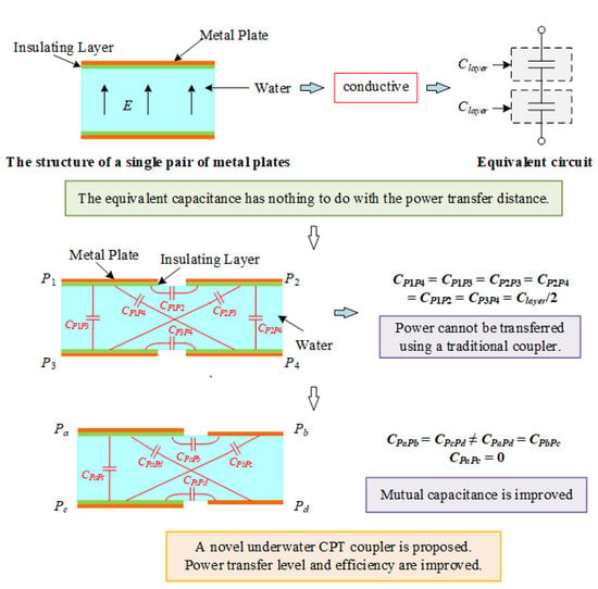
Common underwater CPT couplers typically consist of two pairs of metal plates and insulating layers. Insulating layers are used to isolate the metal plates from the water medium. Before delving into the study of underwater CPT systems, a single pair of metal plates was first studied. The schematic diagram of a single pair metal plates in water medium is shown in Figure 1, where the orange parts represent the metal plates, the green parts represent the insulating layer, and the blue parts represent the water medium. Depending on the conductivity, the water medium can be considered either a non-conductive dielectric or a conductive conductor.
When the water medium acts as a dielectric, the single pair of metal plates illustrated in Figure 1 can be equivalent to the structure shown in Figure 2, where Cmica represents the capacitance equivalently formed by a single insulating layer, while Cwater represents the capacitance equivalently formed by the water medium. The formulas for calculating the capacitances Cmica and Cwater are as follows:
where A represents the surface area of the metal plates, d1 is the thickness of the insulating layer, d2 is the thickness of water, ε0 is the vacuum’s dielectric constant, εr(mica) is the insulation layer’s relative dielectric constant, and εr(water) is the water medium’s relative dielectric constant. In this way, the equivalent capacitance Ceq1 for a single pair of metal plates in water medium could be calculated as
When the water medium behaves as a conductor, current is generated between the plates. Consequently, high-frequency electric fields cannot exist within the conductor. Consequently, the equivalent capacitance Cwater shown in Figure 2 cannot be formed. In this scenario, the equivalent capacitance Ceq2 of the underwater single pair of metal plates is only related to Cmica and Cmica, where
According to (1) and (3), when the water medium behaves as a conductor, the equivalent capacitance of the underwater single pair of metal plates is influenced by d1, εr(mica), and A. It is not dependent on the power transfer distance d2 (i.e., the thickness of water) and the relative dielectric constant of the water medium εr(water).
2.2. Simulation Analysis of the Equivalent Capacitance for a Single Pair of Metal Plates
To validate the accuracy of the theoretical analysis above, this section utilizes Maxwell 16.0 for analysis. A simulation model is constructed based on the structure shown in Figure 1, with aluminum chosen as the material for the metal plates and mica chosen as the material for the insulating layer. The relative dielectric constant of mica εr(mica) is set to 5.7 and the relative dielectric constant of the water medium εr(water) is set to 81. The dimensions of the metal plates are designed to be 200 mm × 200 mm × 2 mm, the thickness of the insulating layer d1 is 4 mm, and the wireless power transmission distance d2 is 4 cm. When the water medium acts as a dielectric, according to (1), the theoretical equivalent capacitances of the insulating layer and water are calculated as follows: Cmica = 504.5 pF and Cwater = 716.9 pF. According to (2), the theoretical equivalent capacitance of the single pair of metal plates Ceq1 is calculated as 186.6 pF. When the water medium behaves as a conductor, according to (3), the theoretical equivalent capacitance of the single pair of metal plates Ceq2 is calculated as 252.25 pF.
To investigate the relationship between the water conductivity and the equivalent capacitance of a single pair of metal plates Ceq, different conductivities of water are tested, including 2 µS/cm, 100 µS/cm, 20,000 µS/cm, and 40,000 µS/cm. When the water conductivity is 2 µS/cm or 100 µS/cm, the water behaves as a dielectric, and when the water conductivity is 20,000 µS/cm or 40,000 µS/cm, the water behaves as a conductor. In addition, the water is replaced by air as a reference. Specific simulation results are shown in Table 2.
According to Table 2, when the conductivity of the water medium is 2 µS/cm or 100 µS/cm, the equivalent capacitance is approximately equal to the theoretical equivalent capacitance Ceq1 where Ceq1 = 186.6 pF. In this case, the water behaves as a dielectric and the equivalent capacitance is essentially unaffected by variations in the water conductivity. Similarly, when the water conductivity is 20,000 µS/cm or 40,000 µS/cm, the equivalent capacitance is approximately equal to the theoretical equivalent capacitance Ceq2 where Ceq2 = 252.25 pF. In this case, the water behaves as a conductor and variations in the water conductivity do not affect the equivalent capacitance of a single pair of metal plates submerged in water. The simulation results validate the theoretical analysis.
According to Table 2, it is evident that the equivalent capacitance significantly increased compared to the air medium, regardless of whether the water medium acts as a dielectric or a conductor. When water acts as a dielectric, its relative dielectric constant is approximately 81 times that of air. As a result, according to (2), the equivalent capacitance of a single pair of metal plates experiences a significant improvement. When water behaves as a conductor, the equivalent capacitance of a single pair of metal plates is independent of the power transmission distance but is inversely proportional to the thickness and relative dielectric constant of the insulating layer. Since the insulating layer is relatively thin and its relative dielectric constant is greater than that of air, according to (3), the equivalent capacitance of the single pair of metal plates also undergoes a significant improvement in this scenario.
In order to investigate the anti-misalignment performance of a single pair of metal plates, this section conducts Maxwell simulations using the coupler depicted in Figure 3. The dimensions of the metal plates are 200 mm × 200 mm × 2 mm, the thickness of the insulating layer d1 is 4 mm, the distance for wireless power transmission d2 is 4 cm, and the distance of misalignment xmis is 10 cm. Specific simulation results are shown in Table 3.
Based on the simulation data from Table 3, when the water conductivity is 2 µS/cm, the equivalent capacitance of a single pair of metal plates is equal to that when the water conductivity is 100 µS/cm. However, compared to Table 2, when the water conductivity is 2 µS/cm or 100 µS/cm, the equivalent capacitances vary with coupler misalignment. Similarly, when the water conductivity is 20,000 µS/cm, the equivalent capacitance of a single pair of metal plates is equal to that when the water conductivity is 40,000 µS/cm. However, comparing this with the simulation data in Table 2 reveals that for these two conductivity values, the equivalent capacitance remains largely unchanged even when misalignment occurs. Therefore, when water acts as a conductor, the equivalent capacitance of a single pair of metal plates is essentially unaffected by misalignment. The equivalent capacitance is only influenced by the relative dielectric constant and thickness of the insulating material, as well as the surface area of the metal plates.
3. Research on Underwater CPT Couplers
The typical structure of an underwater CPT coupler is shown in Figure 4. Insulating layers separate metal plates from the water. For the CPT coupler depicted in Figure 4, any two metal plates can form an equivalent capacitance, resulting in six equivalent capacitances, C12, C13, C14, C23, C24, and C34, where the main capacitances are C13 and C24, the cross capacitances are C14 and C23, and the leakage capacitances are C12 and C34. The corresponding equivalent circuit to Figure 4 is shown in Figure 5. Furthermore, the relationship between the equivalent mutual capacitance CM and the six capacitance values mentioned above can be calculated as:
As mentioned in Section 2, when water behaves as a conductor, the equivalent capacitance of a single pair of metal plates under water is independent of misalignment. Therefore, it can be assumed that C13 formed by P1 and P3 is approximately equal to C14 formed by P1 and P4. According to (4), in this scenario, the equivalent mutual capacitance CM of the underwater CPT coupler is approximately zero, making it challenging for electrical energy transmission.
To verify the above analysis, simulations are conducted using Maxwell simulation software based on the structure shown in Figure 4. The dimensions of the metal plates are 200 mm × 200 mm × 2 mm. The insulating material is mica. The thickness of a single mica layer d1 is 4 mm. The power transmission distance d2 is 4 cm. The distance between P1 and P2 or P3 and P4 is set to 1 cm. The relative dielectric constant of mica εr(mica) is 5.7, and the relative dielectric constant of the water εr(water) is 81. Specific simulation results are shown in Table 4, where the main capacitance C13 = C24, the cross capacitance C14 = C23, and the leakage capacitance C12 = C34. Furthermore, in order to facilitate a more accurate comparison, simulations are also conducted by replacing water with air in the simulation model.
When the water conductivity is 2 µS/cm or 100 µS/cm, the water acts as a dielectric. Due to the relative dielectric constant of water being 81, compared to air, the mutual capacitance CM experiences a significant increase, as indicated in Table 4. When the water conductivity is 20,000 µS/cm or 40,000 µS/cm, the mutual capacitance CM is approximately zero. In this scenario, the transmission of electrical energy becomes challenging. The simulation analysis aligns with the theoretical analysis.
As water in the natural world possesses some level of conductivity, achieving high-performance electrical energy transmission in underwater CPT systems requires an increase in the mutual capacitance CM. This can be achieved by widening the gap between the main capacitance and the cross capacitance according to (4). As analyzed in Section 2, the main capacitances and cross capacitances are only determined by the thickness and relative dielectric constant of the insulating material, along with the surface area of the metal plates. To achieve an improvement in CM, the gap between the main capacitances and the cross capacitances of the underwater CPT coupler should be enlarged.
4. Analysis of an Underwater CPT System Based on a Novel Coupler
4.1. Design of a Novel Underwater CPT Coupler
Based on the analysis above, when water is dielectric, the equivalent mutual capacitance CM significantly increases. However, when water is conductive, the equivalent mutual capacitance CM approaches zero, making electrical energy transmission challenging. Natural water found in the environment contains impurities and ions, exhibiting varying degrees of electrical conductivity. Compared to good conductors like copper and silver, natural water has relatively high electrical resistivity. As a result, the equivalent resistance of underwater couplers cannot be ignored, and significant electrical losses will occur, thereby affecting the overall performance of underwater CPT systems. Since the equivalent mutual capacitance CM of traditional underwater CPT couplers approaches zero, a novel CPT coupler with higher power transmission levels and efficiency should be proposed.
The novel underwater CPT coupler proposed in this paper is shown in Figure 6. In this design, the metal plates are made of aluminum, and the dimensions of metal plates Pa and Pc are set to 200 mm × 200 mm × 2 mm. To reduce the size of the coupler, metal plates Pb and Pd have dimensions of 100 mm × 100 mm × 2 mm. To enhance the equivalent mutual capacitance CM of the underwater CPT coupler, insulating material is applied to isolate Pa and Pc from the water. Metal plates Pb and Pd are in direct contact with the water without insulation on their surfaces.
The equivalent circuit of the proposed CPT coupler is shown in Figure 7. Each branch of the circuit is modeled as a combination of equivalent capacitance and equivalent conductance. The components Cac, Cab, Ccd, Cbc, and Cad represent the equivalent capacitances formed by the coupling of metal plates Pa and Pc, Pa and Pb, Pc and Pd, Pb and Pc, and Pa and Pd, respectively. To measure the losses in the coupler, Gac, Gab, Gad, Gcd, Gbc, and Gbd represent equivalent conductances.
As the transmission distance increases, the equivalent conductance decreases, resulting in a lower power transfer efficiency. To reduce power losses, metal plates Pa and Pc, as well as Pb and Pd, are kept in close proximity. In the envisioned practical application, the overall structure of the underwater CPT system is depicted in Figure 8, where the equivalent electrical conductance Gbd in Figure 7 approaches infinity. To simplify the analysis, this paper sets Cad = Cbc, Gad = Gbc, Cab = Ccd, and Gab = Gcd, with the conductance Gbd approaching infinity, as mentioned earlier.
4.2. Analysis of the Underwater CPT System with a Double-Sided LC Compensation Circuit
A parallel model is used to represent the equivalent conductance and resistance between the underwater metal plates. In reality, the parameters between the metal plates do not follow a simple parallel relationship. Thus, the specific values of related parameters cannot be measured using an LCR analyzer. And it is necessary to build a CPT system to measure the equivalent parameters of the underwater CPT system.
Many high-performance compensation circuits have been proposed, such as the double-sided LC compensation circuit [12,29] and the double-sided LCLC compensation circuit [30,31]. The double-sided LC-compensated CPT circuit is selected to conduct experiments due to its advantages of simple construction and good filter capacity. As shown in Figure 10, the input inverter consists of four MOSFETs Q1,2,3,4. The DC voltage UDC is converted to a square-wave voltage vAB. Since a higher order compensation circuit is applied, fundamental harmonic approximation (FHA) is used. For the underwater CPT system, it is necessary to choose an appropriate frequency f to achieve the input zero phase angle (ZPA). This helps eliminate most input reactive power and achieve a soft switching of MOSFETs.
To simplify the analysis, the CPT circuit shown in Figure 10 can be made equivalent to the circuit shown in Figure 11. The DC voltage source UDC in Figure 10 generates a square wave voltage vAB through the full-bridge inverter circuit, where the duty cycle of the full-bridge inverter circuit is represented as D. The vIN shown in Figure 11 represents the fundamental component of vAB, and it can be calculated as:
If the equivalent load is RE, then RE = (8/π2) RL. Defining L1 = L2, Cpri = Cex1 + CP1, Csec = Cex2 + CS1, and Cex1 = Cex2, the equivalent capacitors Cpri = Csec. The expression of input impedance Zin is given by
The expression for the input current iIN is
The expression for the output current iR is
The expressions for Z1, Z2, and ZL are defined as Z1 = 1/(jεCpri + GP1), Z2 = 1/(jεCM1 + Gm1), and ZL = 1/(jεL1).
The expression for the output voltage vR is
After rectifying and filtering, the output voltage is given by
According to Figure 8, the proposed CPT coupler exhibits symmetry between the primary and secondary sides. Therefore, for the proposed CPT coupler, there are four unknown parameters within the coupler, namely Gm1, CM1, GP1 = GS1, and CP1 = CS1. Thus, it is necessary to establish four independent equations to solve for these four unknown parameters. A flow chart for solving the equivalent parameters of the proposed coupler is given in Figure 12.
Two different resistive loads, R1 and R2, are selected. Parameters UDC, Cex1, Cex2, L1, and L2 are all predesigned. When the load is R1, the operating frequency is adjusted until the input impedance becomes approximately resistive. Then, current operating frequency fR1, input power P(R1), and output voltage UO(R1) are all recorded. When the load is R2, the operating frequency is adjusted until the input impedance becomes approximately resistive. Then, the current operating frequency fR2, input power P(R2), and output voltage UO(R2) are recorded. Substituting measured parameters fR1, P(R1), fR2, and P(R2) into (7) and (10), parameters Gm1, CM1, GP1, and CS1 of the proposed CPT coupler can be calculated.
To validate the calculated parameters, a new experiment using a third resistive load R3 is carried out. The frequency fR3, input power P(R3), output voltage UO(R3), and the DC-to-DC efficiency are measured when the circuit achieves input ZPA. Calculate the theoretical efficiency of the double-sided LC-compensated CPT circuit. If the measured efficiency is approximately equal to the theoretical value, it proves that the calculated parameters Gm1, CM1, GP1, and CP1 are correct.
5. Experimental Validation
To validate the above analysis, an underwater double-sided LC-compensated CPT circuit was constructed based on the proposed underwater CPT coupler. The overall structure of the underwater CPT coupler in the experiment is shown in Figure 13. A water tank is used to simulate the underwater environment, with dimensions of approximately 50 cm in length, 40 cm in width, and 30 cm in height. Metal plates are made of aluminum, with only one pair of metal plates insulated. The dimensions of the metal plates are 200 mm × 200 mm × 2 mm. The insulating material used is PVC with a thickness of dPVC = 4 mm. To prevent water seepage, the metal plates and insulation layers are sealed in airtight bags with a thickness of 200 microns. The dimensions of the other pair of metal plates are 100 mm × 100 mm × 2 mm. These two pairs of metal plates were fully immersed in the tap water without insulation.
Microcontroller TMS320F28335 is used to drive Q1,2,3,4. SiC MOSFETs IMW120R045M1 are selected to construct the inverter. SiC diodes IDW30G65C5 are adopted to realize rectification. The TMS320F28335 DSP has a high-speed processing capability of 150 MHz, up to six enhanced pulse width modulator (EPWM) modules, and an easy-to-implement PWM output control program. Therefore, the TMS320F28335 is suitable for generating high-frequency inverter drive signals [32]. The compensation capacitors Cex1 and Cex2 are set to 1 nF, while the compensation inductors L1 and L2 are set to 240 µH. Two loads, R1 = 50 Ω and R2 = 200 Ω, are chosen in this experiment. All components except the CPT coupler are assumed to operate in ideal conditions with no parasitic parameters. Therefore, any losses observed during the experiment are solely attributed to the coupler.
Experimental waveforms are shown in Figure 14, where vGS is the drive voltage of the switching devices, vAB is the high-frequency input voltage, iIN is the input current, and UO is the output voltage. According to Figure 14, for different loads R1 and R2, the input currents are nearly in phase with the input voltages, respectively. This indicates that the input ZPA are all realized.
Experimental parameters of the double-sided LC-compensated CPT circuit with different loads are shown in Table 5. Since the tap water is conductive and the equivalent resistor of the tap water is quite large, a significant amount of output power is wasted, resulting in reduced efficiency compared to the air. As a result, the analysis conducted for the double-sided LC-compensated CPT circuit in the air is not applicable to underwater CPT systems.
The efficiency η shown in Table 5 represents the measured efficiency from the DC source to the DC load. Although the efficiency of the underwater CPT circuit with the proposed coupler is still relatively low, there has been an improvement in both power transfer level and efficiency compared to previous related research. Following the design process shown in Figure 12, when R1 = 50 Ω, parameters PIN, UDC, and UO in Table 5 are substituted into (7) and (10). Similarly, when R2 = 200 Ω, parameters PIN, UDC, and UO in Table 5 are substituted into (7) and (10). With the aforementioned four equations, the equivalent parameters of the proposed coupler can be derived. Relevant parameters are given in Table 6.
To validate the aforementioned parameter calculation procedure, a verification experiment is conducted with R3 = 10 Ω. The experimental waveform is shown in Figure 15. The operating frequency f3 is 274.76 kHz, and the input voltage and input current are nearly in phase, which indicates that nearly all input ZPA and soft-switching of MOSFETs are achieved. The measured input power and DC-DC efficiency with R3 = 10 Ω are 39.89 W and 19%, respectively. With the equivalent parameters of the proposed coupler shown in Table 6, the theoretical efficiency for load R3 = 10 Ω is calculated to be 22.2%. The measured efficiency closely matches the theoretical calculation, demonstrating the correctness of the parameter calculation procedure. The gap between the measured efficiency and the theoretical efficiency is caused by parasitic parameters in the inverter circuit, compensation network, and rectifier circuit.
According to the experimental analysis, the innovative points of this paper are mainly reflected in two aspects. Firstly, the proposed underwater coupler and the parameter design procedure function effectively. According to Figure 14 and Figure 15, it can be observed that the proposed underwater CPT system is capable of achieving both input ZPA and predesigned output power. Secondly, there is an improvement in both the output power and efficiency of the underwater CPT system. The operating frequency, output power, and efficiency of the proposed coupler submerged in tap water are given in Table 7. Compared to previous research given in Table 1, the proposed underwater system is more suitable for practical implementation.
For a better comparison with other studies, Table 7 summarizes the coupler structure, transmission power, and transmission efficiency of the proposed underwater CPT system. The output power and efficiency of the proposed CPT system are still relatively low. However, compared to [25], shown in Table 1, the proposed CPT system can operate in natural water environments. Compared to [4,26,28], since the operating frequency is 275 kHz, the proposed CPT system can operate within the most frequently utilized frequency range. Compared to [27], the transferred power and efficiency are all improved. In addition, as mentioned in the Introduction, in [4,26,27,28], only a small amount of water is added between the metal plates of the CPT coupler. Clearly, when the metal plates are fully immersed in a larger water tank, the system’s efficiency would significantly decrease.
Based on the newly designed coupler in this paper, with a working frequency of 275 kHz, it achieves several tens of watts of power transmission in tap water. Without efficiency optimization, the maximum efficiency is 34.85%. Therefore, compared to existing research, the underwater CPT coupler designed in this paper not only reduces design complexity but also enhances the performance of the CPT system in tap water. However, in-depth research is still needed to further improve the efficiency of underwater CPT systems.
6. Conclusions
This paper analyses the single pair and two pairs of metal plates in different media with varying electrical conductivity. Since natural water is conductive, the traditional CPT coupler used in air cannot realize power transfer in water. Thus, after a comprehensive analysis of underwater CPT couplers, a novel CPT coupler is proposed to improve the power transfer level and efficiency of underwater CPT systems. To calculate the equivalent capacitances and conductance of the novel CPT coupler, a double-sided LC-compensated CPT circuit with the proposed CPT coupler submerged in tap water is built. The operating frequency is 275 kHz, efficiency is 34.85%, and the input power is 38.8 W. Through experimental validation, it is demonstrated that compared to traditional underwater CPT systems, the power transfer level and efficiency of the double-sided LC-compensated CPT circuit are improved, expanding the applicability of CPT technology. However, unlike IPT, which has been developed for a long time, researches of CPT technology in both air and water mediums have only been carried out very recently. In order to put CPT systems into practice as soon as possible, it is important to work out the operating principle of the underwater CPT and enhance the power transfer distance, power transfer level, and efficiency of the whole system.
Author Contributions
Methodology, X.Z.; validation, J.L.; writing—original draft, X.Z.; supervision, J.L. All authors have read and agreed to the published version of the manuscript.
Funding
This research is supported by the Jiangsu Key Laboratory of Smart Grid Technology and Equipment, Southeast University, 4216002201 and the Startup Foundation for Introducing Talent of NUIST, 2023r111.
Data Availability Statement
Data are contained within the article.
Conflicts of Interest
The authors declare no conflict of interest.
References
- Bogue, R. Underwater robots: A review of technologies and applications. Ind. Robot. Int. J. 2015, 42, 186–191. [Google Scholar] [CrossRef]
- Sahoo, A.; Dwivedy, S.K.; Robi, P. Advancements in the field of autonomous underwater vehicle. Ocean. Eng. 2019, 181, 145–160. [Google Scholar] [CrossRef]
- Rong, E.; Sun, P.; Zhang, X.; Yang, G.; Wu, X. 3.3 kW Underwater Capacitive Power Transfer System for Electric Ship Charging Application. In Proceedings of the 2023 IEEE International Conference on Power Science and Technology (ICPST), Kunming, China, 5–7 May 2023; pp. 1052–1057. [Google Scholar]
- Tamura, M.; Naka, Y.; Murai, K.; Nakata, T. Design of a capacitive wireless power transfer system for operation in fresh water. IEEE Trans. Microw. Theory Tech. 2018, 66, 5873–5884. [Google Scholar] [CrossRef]
- Hayslett, T.M.; Orekan, T.; Zhang, P. Underwater wireless power transfer for ocean system applications. In Proceedings of the OCEANS 2016 MTS/IEEE Monterey, Monterey, CA, USA, 19–23 September 2016; IEEE: Toulouse, France, 2016; pp. 1–6. [Google Scholar]
- Yang, L.; Li, X.; Zhang, Y.; Feng, B.; Yang, T.; Wen, H.; Tian, J.; Zhu, D.; Huang, J.; Zhang, A.; et al. A review of underwater inductive wireless power transfer system. IET Power Electron. 2023. [Google Scholar] [CrossRef]
- Sun, P.; Wu, X.; Cai, J.; Wang, X.; Zhang, X.; Liang, Y.; Xiong, Q.; Rong, E. Eddy current loss analysis and frequency optimization design of double-sided LCC-IPT system in seawater environment. Sci. China Technol. Sci. 2022, 65, 407–418. [Google Scholar] [CrossRef]
- Kim, J.; Kim, H.; Kim, D.; Park, J.; Park, B.; Huh, S.; Ahn, S. Analysis of eddy current loss for wireless power transfer in conductive medium using Z-parameters method. In Proceedings of the 2020 IEEE Wireless Power Transfer Conference (WPTC), Piscataway, NJ, USA, 15–19 November 2020; IEEE: Toulouse, France, 2020; pp. 432–434. [Google Scholar]
- Mahdi, H.; Hoff, B.; Østrem, T. Optimal solutions for underwater capacitive power transfer. Sensors 2021, 21, 8233. [Google Scholar] [CrossRef]
- Zhang, H.; Lu, F.; Hofmann, H.; Liu, W.; Mi, C.C. A four-plate compact capacitive coupler design and LCL-compensated topology for capacitive power transfer in electric vehicle charging application. IEEE Trans. Power Electron. 2016, 31, 8541–8551. [Google Scholar]
- Lu, F.; Zhang, H.; Mi, C. A two-plate capacitive wireless power transfer system for electric vehicle charging applications. IEEE Trans. Power Electron. 2017, 33, 964–969. [Google Scholar] [CrossRef]
- Lu, F.; Zhang, H.; Hofmann, H.; Mi, C.C. A double-sided LC-compensation circuit for loosely coupled capacitive power transfer. IEEE Trans. Power Electron. 2017, 33, 1633–1643. [Google Scholar] [CrossRef]
- Naka, Y.; Tamura, M. Design of a capacitive coupler for underwater wireless power transfer focused on the landing direction of a drone. IEICE Trans. Electron. 2023, 2023ECP5023. [Google Scholar] [CrossRef]
- Tamura, M.; Murai, K.; Matsumoto, M. Design of conductive coupler for underwater wireless power and data transfer. IEEE Trans. Microw. Theory Tech. 2020, 69, 1161–1175. [Google Scholar] [CrossRef]
- Yang, L.; Ju, M.; Zhang, B. Bidirectional undersea capacitive wireless power transfer system. IEEE Access 2019, 7, 121046–121054. [Google Scholar] [CrossRef]
- Zhang, H.; Lu, F. Feasibility study of the high-power underwater capacitive wireless power transfer for the electric ship charging application. In Proceedings of the 2019 IEEE Electric Ship Technologies Symposium (ESTS), Washington, DC, USA, 14–16 August 2019; pp. 231–235. [Google Scholar]
- Lu, F.; Zhang, H.; Mi, C. A review on the recent development of capacitive wireless power transfer technology. Energies 2017, 10, 1752. [Google Scholar] [CrossRef]
- Abramov, E.; Alonso, J.M.; Peretz, M.M. Analysis and behavioural modelling of matching networks for resonant-operating capacitive wireless power transfer. IET Power Electron. 2019, 12, 2615–2625. [Google Scholar] [CrossRef]
- Sinha, S.; Kumar, A.; Regensburger, B.; Afridi, K.K. A new design approach to mitigating the effect of parasitics in capacitive wireless power transfer systems for electric vehicle charging. IEEE Trans. Transp. Electrif. 2019, 5, 1040–1059. [Google Scholar] [CrossRef]
- Ageev, I.; Rybin, Y.M. Features of Measuring the Electrical Conductivity of Distilled Water in Contact with Air. Meas. Tech. 2020, 62, 923–927. [Google Scholar] [CrossRef]
- Pawlowicz, R. Calculating the conductivity of natural waters. Limnol. Oceanogr. Methods 2008, 6, 489–501. [Google Scholar] [CrossRef]
- Pryor, R.W. Inductive conductivity measurement of seawater. In Proceedings of the COMSOL Conference, Rotterdam, The Netherlands, 23–25 October 2013. [Google Scholar]
- Huang, L.; Hu, A.P. Defining the mutual coupling of capacitive power transfer for wireless power transfer. Electron. Lett. 2015, 51, 1806–1807. [Google Scholar] [CrossRef]
- Mahdi, H.; Hoff, B.; Østrem, T. Maximum available efficiency of undersea capacitive coupling in a wireless power transfer system. In Proceedings of the 2021 IEEE 30th International Symposium on Industrial Electronics (ISIE), Kyoto, Japan, 20–23 June 2021; IEEE: Piscataway, NJ, USA, 2021; pp. 1–5. [Google Scholar]
- Zhang, H.; Lu, F. Insulated coupler structure design for the long-distance freshwater capacitive power transfer. IEEE Trans. Ind. Inform. 2019, 16, 5191–5201. [Google Scholar] [CrossRef]
- Tamura, M.; Murai, K.; Naka, Y. Capacitive coupler utilizing electric double layer for wireless power transfer under seawater. In Proceedings of the 2019 IEEE MTT-S International Microwave Symposium (IMS), Boston, MA, USA, 2–7 June 2019; IEEE: Piscataway, NJ, USA, 2019; pp. 1415–1418. [Google Scholar]
- Urano, M.; Ata, K.; Takahashi, A. Study on underwater wireless power transfer via electric coupling with a submerged electrode. In Proceedings of the 2017 IEEE International Meeting for Future of Electron Devices, Kansai (IMFEDK), Kyoto, Japan, 29–30 June 2017; IEEE: Piscataway, NJ, USA, 2017; pp. 36–37. [Google Scholar]
- Tamura, M.; Naka, Y.; Murai, K. Design of capacitive coupler for wireless power transfer under fresh water focusing on kQ product. In Proceedings of the 2018 IEEE/MTT-S International Microwave Symposium-IMS, Philadelphia, PA, USA, 10–15 June 2018; IEEE: Piscataway, NJ, USA, 2018; pp. 1257–1260. [Google Scholar]
- Yi, L.; Moon, J. Design of efficient double-sided LC matching networks for capacitive wireless power transfer system. In Proceedings of the 2021 IEEE PELS Workshop on Emerging Technologies: Wireless Power Transfer (WoW), San Diego, CA, USA, 1–4 June 2021; IEEE: Piscataway, NJ, USA, 2021; pp. 1–5. [Google Scholar]
- Lu, F.; Zhang, H.; Hofmann, H.; Mi, C.C. A Double-Sided LCLC-Compensated Capacitive Power Transfer System for Electric Vehicle Charging. IEEE Trans. Power Electron. 2015, 30, 6011–6014. [Google Scholar] [CrossRef]
- Gao, F.; Wang, Z.; Li, L.; Wang, S.; Deng, J. Analysis and design of double-sided LCLC compensation parameters with coupling-insensitive ZVS operation for capacitive power transfer. In Proceedings of the 2019 IEEE Energy Conversion Congress and Exposition (ECCE), Baltimore, MD, USA, 29 September–3 October 2019; IEEE: Piscataway, NJ, USA, 2019; pp. 576–581. [Google Scholar]
- Pang, S.; Xu, J.; Li, H.; Ma, Q.; Li, X. Dual-Frequency Modulation to Achieve Power Independent Regulation for Dual-Load Underwater Wireless Power Connector. IEEE J. Emerg. Sel. Top. Power Electron. 2022, 11, 2377–2389. [Google Scholar] [CrossRef]
Figure 1.
The structure of a single pair of metal plates in water medium.

Figure 2.
Equivalent capacitances of Figure 1.
Figure 2.
Equivalent capacitances of Figure 1.

Figure 3.
The structure of a single pair of metal plates in water medium with misalignment.

Figure 4.
The structure of a symmetrical underwater CPT coupler.

Figure 5.
The equivalent circuit of a symmetrical underwater CPT coupler.

Figure 6.
The novel underwater CPT coupler.

Figure 7.
The equivalent circuit of the proposed CPT coupler.

Figure 8.
An underwater CPT system in practical application.

Figure 9.
The simplified circuit of the proposed CPT coupler.

Figure 10.
An underwater CPT circuit based on the double-sided LC compensation network.

Figure 11.
The simplified double-sided LC-compensated CPT circuit.

Figure 12.
Flow chart for solving equivalent parameters of the proposed coupler.

Figure 13.
The structure of the proposed CPT coupler.

Figure 14.
Experiment waveforms of the underwater CPT circuit. (a) R1 = 50 Ω; (b) R2 = 200 Ω.


Figure 15.
Waveforms of vGS, vAB, iIN, and IO when R3 = 10 Ω.


Table 1.
The coupler structure, transmission power, and transmission efficiency of the existing underwater CPT system.
Table 1.
The coupler structure, transmission power, and transmission efficiency of the existing underwater CPT system.
| Reference | Insulation | Water Types | Transfer Distance | Input Power | Efficiency |
|---|---|---|---|---|---|
| [25] | All four aluminum plates are insulated | 2 µS/cm | 500 mm | 365 W | 60.17% (R = 37.5 Ω) |
| [26] | All four metal plates are uninsulated | Seawater | 5 mm | \ | 55.3% (f = 308 Hz) |
| [27] | Only one pair of plates is insulated | Tap water | 5 mm | 51.8 mW | 62.4% (R = 3 kΩ) |
| [28] | All four metal plates are uninsulated | Tap water | 20 mm | \ | 85.1% (f = 33.3 MHz) 80.9% (f = 25.7 MHz) |
| [4] | All four metal plates are uninsulated | Freshwater | 20 mm | 400 W | 90% (f = 107.7 MHz) |
Table 2.
Equivalent capacitances of a single pair of metal plates in different media.
| Conductivity | 2 µS/cm | 100 µS/cm | 20,000 µS/cm | 40,000 µS/cm | Air |
|---|---|---|---|---|---|
| Equivalent capacitance | 188.32 pF | 188.32 pF | 254.8 pF | 254.8 pF | 9.43 pF |
Table 3.
Simulation values of equivalent capacitances of a single pair of metal plates in different media with misalignment.
Table 3.
Simulation values of equivalent capacitances of a single pair of metal plates in different media with misalignment.
| Conductivity | 2 µS/cm | 100 µS/cm | 20,000 µS/cm | 40,000 µS/cm | Air Dielectric |
|---|---|---|---|---|---|
| Equivalent capacitance | 131.09 pF | 131.09 pF | 256 pF | 256 pF | 7.07 pF |
Table 4.
Equivalent capacitances of CPT couplers in different media.
| Conductivity | 2 µS/cm | 100 µS/cm | 20,000 µS/cm | 40,000 µS/cm | Air Dielectric |
|---|---|---|---|---|---|
| Main capacitance | 172.5 pF | 172.5 pF | 128.2 pF | 128.1 pF | 9.7 pF |
| Cross capacitance | 17.6 pF | 17.6 pF | 128.2 pF | 128.2 pF | 0.43 pF |
| Leakage capacitance | 20.4 pF | 20.4 pF | 129.0 pF | 128.7 pF | 2.4 pF |
| Mutual capacitance | 77.45 pF | 77.45 pF | 0 | 0 | 4.62 pF |
Table 5.
Measured parameters of the double-sided LC-compensated CPT circuit in tap water.
| RL | f | PIN | UDC | UO | η |
|---|---|---|---|---|---|
| 50 Ω | 274.7 kHz | 38.8 W | 40 V | 26 V | 34.85% |
| 200 Ω | 276.3 kHz | 47.78 W | 40 V | 48 V | 24.11% |
Table 6.
Equivalent capacitances and conductance of the underwater coupler.
| Gm1 | GP1 = GS1 | CM1 | CP1 = CS1 |
|---|---|---|---|
| 1.786 × 10⁻⁵ S/m | 7.194 × 10⁻⁵ S/m | 105 pF | 251 pF |
Table 7.
The coupler structure, transmission power, and transmission efficiency of the proposed coupler.
Table 7.
The coupler structure, transmission power, and transmission efficiency of the proposed coupler.
| Insulation | Water Types | Transfer Distance | Input Power | Efficiency |
|---|---|---|---|---|
| Only one pair of plates is insulated | Tap water | 8 mm | 38.8 W | 34.85% (R = 50 Ω) |
Disclaimer/Publisher’s Note: The statements, opinions and data contained in all publications are solely those of the individual author(s) and contributor(s) and not of MDPI and/or the editor(s). MDPI and/or the editor(s) disclaim responsibility for any injury to people or property resulting from any ideas, methods, instructions or products referred to in the content. |
© 2023 by the authors. Licensee MDPI, Basel, Switzerland. This article is an open access article distributed under the terms and conditions of the Creative Commons Attribution (CC BY) license (https://creativecommons.org/licenses/by/4.0/).
Share and Cite
MDPI and ACS Style
Zhang, X.; Lian, J. A Novel Coupler of Capacitive Power Transfer for Enhancing Underwater Power Transfer Characteristics. Electronics 2024, 13, 74. https://doi.org/10.3390/electronics13010074
AMA Style
Zhang X, Lian J. A Novel Coupler of Capacitive Power Transfer for Enhancing Underwater Power Transfer Characteristics. Electronics. 2024; 13(1):74. https://doi.org/10.3390/electronics13010074
Chicago/Turabian StyleZhang, Xueqiang, and Jing Lian. 2024. "A Novel Coupler of Capacitive Power Transfer for Enhancing Underwater Power Transfer Characteristics" Electronics 13, no. 1: 74. https://doi.org/10.3390/electronics13010074
Note that from the first issue of 2016, this journal uses article numbers instead of page numbers. See further details here.