
A Critical Review on Channel Modeling: Implementations, Challenges and Applications


1
Zhejiang University-University of Illinois Urbana Champaign (ZJU-UIUC) Institute, Haining 314406, China
2
School of Electrical and Electronic Engineering, University College Dublin, D04 V1W8 Dublin, Ireland
3
School of Opto-Electronic Engineering, Zaozhuang University, Zaozhuang 277160, China
4
Faculty of Computer and Information Technology, University of Tabuk, Tabuk 71491, Saudi Arabia
5
School of Computing & Data Science, Wentworth Institute of Technology, Boston, MA 02115, USA
6
Faculty of Computers and Information, Menoufia University, Shebin Al-Kom 32511, Egypt
*
Author to whom correspondence should be addressed.
Electronics 2023, 12(9), 2014; https://doi.org/10.3390/electronics12092014
Submission received: 8 March 2023
/
Revised: 28 March 2023
/
Accepted: 18 April 2023
/
Published: 26 April 2023
(This article belongs to the Section Electrical and Autonomous Vehicles)
Abstract
:In recent years, the use of massive multiple-input multiple-output (MIMO) systems and higher frequency bands for next-generation urban rail transportation systems has emerged as an intriguing research topic due to its potential to significantly increase network capacity by utilizing available narrowband and broadband spectrums. In metro and mining applications, the high-reliability wireless sensor network (WSN) plays a vital role in providing personal safety, channel optimization, and improving operational performance. Through the duration of 1921–2023, this paper provides the survey on the progress of fifth-generation (5G) and beyond-fifth-generation (B5G) wireless communication systems in underground environments such as tunnels and mines, the evolution of the earliest technologies, development in channel modeling for vehicle-to-vehicle (V2V) communications, and realization of different wireless propagation channels in high-speed train (HST) environments. In addition, the most recent advanced channel modeling methods are examined, including the development of new algorithms and their use in intelligent transportation systems (ITS); mathematical, analytical, and experimental techniques for propagation design; and the significance of the radiation characteristics, antenna placing, and physical environment effect on wireless communications. Leaky coaxial cable (LCX) and distributed antenna system (DAS) designs are introduced in the demonstrated systems for improving the channel capacity of narrowband and wideband channels as well as the spatial characteristics of various MIMO systems. The review article concludes by figuring out open research directions for future technologies.
1. Introduction
Recently, the short-range wireless communication has gained popularity among the underground communications community as an integral component of a strategy to increase labor productivity and safety. Leaky coaxial cables (LCXs), which employ multipath propagations, have recently emerged as a key tool for improving wireless local area network (WLANs) capacity in communication-based train control (CBTC) systems, high-speed trains, automatic highways, and underground conveyance applications [1,2]. The amount of user traffic on mobile networks is dramatically rising as a result of the growing use of smartphones, laptops, tablets, and countless other application services. The initial contribution to deploy the wireless technology in underground environment and tunnels belongs to the 1920s [3]; however, the majority of this research lacked theoretical modeling and depended exclusively on experimental data. Moreover, the given research was conducted at a comparatively lower frequency band and only achieved a small number of objectives due to the frequently encountered path loss issues [4]. Therefore, the safety boards and government authorities in North America and Europe in the 1960s and 1970s supported the use of very high frequency-frequency modulation (VHFFM) moveable radio channels for enhancing communications quality with underground workers due to safety concerns [3]. At very high frequency (VHF), the wireless system performance in underground carriage tunnels and mines is found to be very poor because of the inner structure of propagating medium and the waveguide effect. Although conventional antenna-based channels have played a significant role in underground communications over the past five decades, they are not flexible enough to accommodate recently developed technologies and wireless standards that offer much higher efficiency and better capabilities, such as integrated data and voice. In the vehicle-to-vehicle (V2V) environment, the intelligent reconfigurable surface (IRS) has recently gained a lot of attention and is emerging as a viable paradigm for beyond-fifth-generation (B5G) communication systems [5]. IRS is a passive beamforming device that uses an artificial programmable structure with multiple passive reflecting parts to manipulate incident electromagnetic waves in desired directions. Due to the passive nature of IRS, current studies mostly focus on IRS design with perfect channel state information (CSI), which is challenging for channel acquisition [6]. Recent interest in the deployment of next-generation intelligent transport systems (ITS) in underground tunnels has stemmed from the potential to enhance the tunnel environment productivity and efficiency through efficient voice communication, from a better approach towards the management of data systems and automatic dispatch [7,8], from recent models for wireless personal area network (WPAN) devices, and from short-distance millimeter-wave (mmWave)-based wireless communication networks.
In the literature, numerous studies have been perceived to improve the data rates and capacity of a channel for long-term evolution for metro (LTE-M) systems. Passengers need to acquire the statistics of the train environment and location with the access of dynamical applications via their mobile phones [9]. In underground tunnels, the electromagnetic ray attenuation becomes crucial after many times of scattering and reflections from the walls, floor, and ground when the conventional antenna systems are installed. The radiation characteristics and antenna parameters have substantial effects on field coverage [10,11]. Radiated leaky coaxial cables (LCX), generally known as the leaky feeders, were established in the late 1950s to prolong the transmission of VHF channels into relatively shorter underground conveyance tunnels, and such structures can be mostly found in urban areas [12]. The typical LCX is a linear slot-structured array with stable phase delays between the two adjacent slots. These slots are thought to break into infinite metallic planes that have a substantial impact on the electromagnetic field [13]. In recent years, radiating cables, which operate in the ultra-high frequency range, have been widely used as a crucial component of wireless communication channels in underground environments. Examples of such applications include radio detection systems, distributed antenna systems for indoor cellular environments, and wireless indoor positioning systems [14,15]. Consequently, the development of optimal propagation model is a tough task. Compared to single-input single-output (SISO) channels, the multiple-input multiple-output (MIMO), which utilizes hundreds or even more antennas, has grasped immense attention recently due to its potential of providing higher data rates. The MIMO system performance is greatly sensitive to the LCX array orientation due to the lower angular spread induced by the waveguide effect inside different tunnels. The separating distance between antennas and the leaky cable has a reasonable impact on the outcome of the MIMO channel; thus, by properly adjusting this distance and other factors, a reliable and stable performance can be acquired, which is important for the underground radio communications.
1.1. Motivation and Contributions
All the aforementioned papers did not consider the modeling requirements of LCX and distributed antenna system (DAS)–based massive MIMO channels in mine and tunnel environments. In this review, we propose not only the latest technologies significance but also at the same time review the efficient developed models for channel propagation in underground mines and tunnels. This could be an obstacle for readers who desire to obtain expertise in this research field or intend to perceive more knowledge about wireless communications. In this review, we propose a thorough guidance for the massive MIMO system characteristics and different techniques to improve the channel capacity. More precisely, the major objectives are as follows:
- LCX-based Enhanced Channel Performance and Classification: Our intention is to bring earlier research into consideration, classify gaps and directions, and summarize achievements. To assist researchers in determining of a specific study gain in their upcoming research problems regarding wireless communication field, we first review the LCX-based wireless communication incentives by comparing it with the traditional communication techniques. Then, we look into the factors which have greater influence on channel performance such as antenna types, channel modeling schemes, the tunnel or mine geometries, fading characteristics, Doppler effects, wave classification, diffraction, reflection, different challenges to deal with antenna configurations, etc.
- Massive MIMO Channel Modeling and Challenges: To meet the need for service stability and enhancement, we summarize the important aspects of massive MIMO channels and latest developments of channel modeling schemes in V2V and high-speed train (HST) scenarios. After examining the conventional, LCX, and IRS-based mmWave MIMO channels, we move on to discuss how to deal with challenges related to spatial characteristics, channel correlation, channel capacity, etc.
- Specifying Potential and Research Recommendations: In order to specify the potential techniques to lift the performance of massive MIMO systems, we propose suggestions and emerging ideas for future research directions in wireless communication field.
1.2. Article Structure
The rest of the paper is structured as follows. In Section 2, a concise review about evolution of wireless communications and factors influencing propagation characteristics in confined environments is demonstrated. In Section 3, different parameters which have a large effect on the radiated field are explained thoroughly. In Section 4, we present different channel modeling schemes in tunnel environment. In Section 5, we focus on HST and mmWave channel performance. The future trends and challenges for upcoming research problems are discussed in Section 6. Finally, Section 7 concludes this survey. The acronyms are listed in Table 1. Moreover, the paper schematic representation is given in Figure 1.
2. Establishment of Wireless Communications in Underground Environments
2.1. Wireless Communication’s History and Evolution
In the early days of wireless communication in confined environments such as underground tunnels and mines, the communication system was relying on experimental study without any empirical understanding and theoretical modeling efforts. The initial incentive for underground communication was focusing to facilitate the safety purpose in mines or tunnels by executing man-to-man communication. As underground communication systems have progressed, man-to-machine and further machine-to-machine communications have been accomplished to meet the productivity and effective goals. The wireless signals, when they travel from transmitting antenna (Tx) to a receiving antenna (Rx), practice various propagation phenomena such as diffraction, reflection, refraction, and scattering, as shown in Figure 2. Therefore, the interaction of signals through surroundings may cause disturbance and follow many paths between Tx and Rx. As the replicas come to the Rx after various delays, the signals go through the time dispersion (delay spread). As they take place from multiple directions, the incoming signals go through the angular dispersion [16].
In 1899, N. Tesla proposed to practice extremely-low-frequency (ELF) signals and Earth was used as a transmitting medium in order to deliver messages throughout the world [17]. Interest in wireless communications in underground environments evolved in the late 1920s after the first pioneer of radio was attracted towards the potentials of through-the-earth (TTE) wireless communication. It was continued until the 1940s, when different systems such as TTE signaling systems and current carrier radios were offered by the U.S. Mines Bureau commercially for the emergency operations and ordinary communications in mines [18,19]. To send and receive magnetic waves through the rocks for TTE communications, a ferrite rod antenna or extended loop antenna with a range of a few kilometers is commonly utilized (see Figure 3). In the 1940s, because of the limitations of bulky mobile equipment and low data rates, the initial research on wireless communication in mines and tunnels was ceased [20,21]. The personal emergency device (PED) has been recognized as an emergency cautionary TTE system [22] which practices very-low-frequency (VLF) signals in order to deliver text messages. In the beginning, this was used for one-way communication, but recently it has developed the capability of two-way communications via text messaging [22].
As we all know, under different indoor environments, lower frequencies in the range of 10 MHz (normally cutoff frequency for key modes under various indoor environments) can only cover distances up to 30 m in a vacant tunnel or mine [23]. However, it was also observed that the conductors for example, pipes, electronic wires, and so on, operating in different tunnels, enhance the electromagnetic (EM) propagation by small attenuation and consequently improve the span [17]. Such statistics were not directly acknowledged through experiments, but this resulted in improvement of monofilar techniques in the late 1960s. The monofilar scheme turned out to be a rough guide for the leaky cable system that was broadly used afterwards. Generally, through-the-wire (TTW) signals go through all over the twisted pair, coaxial cable, trolley, and optical fiber against the outer surface or within the tunnel and arrive at the movable apparatus. In the 1950s to 1960s period, scattered antenna systems and leaky feeders were established to boost the coverage range of VHF radio communication schemes for comparatively shorter underground transport tunnels observed in different metropolitan areas for the public benefit and safety [12]. Leaky feeder or leaky coaxial cable (LCX) widely used TTW methodology for communications in underground environments. The cable is named as leaky’ due to carrying slots or gaps on its external conducting sheath, permitting signals to flow out or into the cable beside its full length (see Figure 4). Due to the outflow of signals, line amplifiers need to be injected at fixed intervals, usually after every 250 to 450 m. The main drawbacks of LCX systems are fixed infrastructure, challenging maintenance, short coverage close to the face, and limited capacity, i.e., the area of a mine from where the minerals need to be extracted [18].
The through-the-air (TTA) at ultra-high frequency super-high-frequency technique is one widely used wireless communication technique in underground mines and tunnels. It is proficient in offering numerous applications such as tracking of mineworkers, two-way data and voice communications, video surveillance, remote sensing, and so on. In the early 2000s, the mine industry was fascinated with low data rates technology, for example, passive radio-frequency identification (RFID), active, RFID (about 10 m), zonal intercommunication global-standard (ZigBee), and systems for high data rates (ultra wideband), because they deal with low power, short-range, and positioning competencies. These techniques can support different applications of wireless sensor networks (WSNs). Up to now, WLAN mesh systems are self-healing, self-learning, and redundant, which looks like the ultimate consistent wireless network. If some portion of the system is damaged, the rest proceeds with the functioning, and thus it is particularly required in dynamic environments where link busts are common (mine galleries) [7,24].
Unlike the previous fourth-generation (4G) communication systems, the high transmission data rate is not the exclusive aspect of the 5G communication system. Actually, the 5G systems execute more advanced features such as low power consumption, low latency, and low cost compared to earlier generations (1G–4G) [25,26]. Future wireless communication systems should be IP-based, heterogeneous, and ubiquitous; thus, 5G networks are required to resolve such issues and the integration of various radio access technologies must be fulfilled in 5G [27]. In another way, the 5G systems need to endorse the latest 5G standards and must be consistent with the earlier cellular systems, device-to-device (D2D) communication, and WiFi [28]. For that, the 5G networks need to endorse D2D communication along rapid evolution of the Internet of Things (IoT’s). The objective for D2D communications is to deliver direct communications, low rate in online connections and low power [29].
To deal with the requirements of 5G systems, a growing number of investigations are in progress. As for increasing the transmission data rates within MIMO solutions, another attractive technique is introduced, which is reliant on the expansion of densification to use the spectrum proficiently. There are basically two important techniques for higher densification. The initial one is based on installing large number of base stations (BS) which push cells to shrink into smaller sizes. The objective of using this technique is to enhance the OPEX and CAPEX, which turns this technique into a limited scope. The second technique pursues the multiple RAT’s in a suitable way, which provides guidance for the coexistence of multiple RAT’s and heterogeneous networks. However, the highest speed limit, up to 500 km/h, of the aforementioned techniques is even hard to attain, whereas the vacuum tube ultra-high speed train (vactrain) can achieve a higher speed, up to 1000 km/h [30,31]. In regard to 5G systems, the standardized article 3GPP TR 38.913 [32] specifies that 5G NR can achieve the highest speed, up to 500 km/h. Moreover, the current railway communication systems such as LTE cannot endorse the train-to-ground (T-G) communications for vacuum tube trains. Similar to the current high-speed railways (HSR’s) [33] and maglev trains [34], the T-G wireless communications are critical for the secure operations of vacuum tube trains. The communication systems are responsible for optimizing the reliable and bidirectional data transmission between the ground and train to fulfill the specific requirements of integrated service transmissions [35]. Because of the two distinctive features of vacuum tube trains such as ultra-high speed and closed metallic vacuum tube, the T-G wireless communications for vacuum tube trains will be extra challenging compared to the maglev train and existing HSR [36]. Thus, the wireless communication systems of high performance and high reliability dedicated to the condition of speed approaching up to 1000 km/h need to be explored for the efficient T-G communication requirements of vacuum tube trains.
2.2. Antenna Characteristics
Antennas are considered as the interface between the electric current propagating in metallic conductor and the broadcasted radio waves through space. Antenna design is a key factor in the applications of unmanned aerial vehicles (UAVs) over continued range and obstructed scenarios. However, this is not precisely related to antenna autopilots/tracking. Radiating particles of wire normally radiate power when linked to a supply of RF (Tx or Rx). How nicely it radiates depends upon two factors, as follows:
- While the antenna and applied radio signal are resonant at the similar frequency.
- While the feeding point of antenna is paired with the impedance of transmitting power source.
In MIMO systems, the power distribution becomes more evenly distributed as the angular spread (AS) increases, which further assists in reduction of spatial correlation coefficient under the condition of same antenna spacing. The numerous radiated waves expand the AS boundary, which is actually useful to assist in decorrelation of the spatial channels [37,38]. According to the measurement campaign in Massif Central tunnel, the results determine that horizontally polarized leaky cable has lower correlation coefficient values when compared with the vertically polarized one, and it was established that correlation coefficients decrease nearly to zero at for horizontally polarized LCX and at for vertically polarized LCX, as given in Figure 5. The spatial correlation between different antennas is basically dependent on antenna spacing and the mean AoA. Therefore, the separating distance between antenna elements should be high enough to decrease the correlation.
2.3. Channel Measurement Environment
MIMO systems in tunnels can be classified into two different scenarios: tunnels and stations. Thus, a channel measurement is based on the following scenarios.
2.3.1. Tunnel Environment
The tunnel environment depicts a situation in which train travels through tunnels [40,41] ranging in length from a few hundred meters to many kilometers. The communication channel is significantly influenced by the length, size, and form of the tunnels (rectangular, arched, circular, etc.) as well as the waveguide phenomena encountered. Signal propagation characteristics in tunnels are significantly different from other circumstances due to the long confined space, tunnel boundaries, and roughness of the inner wall. To address the limited vision problem in tunnels, distributed antenna systems (DAS) and leaky cables are frequently used to design an optimum wireless communication system. However, as high-speed trains may need lengthy tunnels, the LCX’s consideration is somehow expensive and difficult to maintain, especially at the high operating frequencies. Therefore, the DAS is more practicable [42]. It can provide improved coverage gains as well as spatial diversity against fading, by placing antenna elements in diverse locations. It also offers advantages in the modern applications, such as ease of maintenance once it is opened and a long distance between repeaters.
2.3.2. Station Environment
The station scenario portrays a railway section where different trains stop to load and unload people on a regular basis [43]. Train stations are divided into categories based on architecture and their sizes. Station scenarios can be classified as marshalling stations, small/medium-size stations, and large stations based on the station configuration, which represents the expected communication traffic. Based on the size perspective, which influences the propagation characteristic of a channel, the train station can be classified into three different scenarios, i.e., closed station, semi-closed station, and open station, as shown in Figure 6.
2.3.3. Tunnel Geometry
Since the prediction of field strength is a crucial factor in the designing of cellular mobile radio systems, many experimental and theoretical methodologies have been established for the terrain profiles and urban environments. However, it is critical not only to study the scenario when the receiver is moving in complex environments such as mountains or towns with multiple diffractions and reflections, the consideration of radio links among different objects (car, train, etc.) standing in the road tunnel is also highly vital. To guarantee the communications within the tunnel, the first solution contains the fixing of LCX besides the tunnel wall. The given principle has been demonstrated in many research articles for different kinds of LCX polarizations, working either below or above the tunnels cut-off frequencies. Though, at higher frequency, normally above few hundreds of MHz for the road tunnels, the actual propagation does not consider the extortionate attenuation and one can presume it at least for shorter tunnels. However, the most crucial point for this kind of telecommunication is the field variations beside the tunnel entryway, and therefore the coupling from outside or inside occurs when the outer incident waves hit the tunnel entry gate or when the transmitter goes inside the tunnel vicinity and radiates in the direction of free space. The uniform theory of diffraction appears well suitable to solve such kinds of problems. Characterization of high-order frequency-based electromagnetic wave propagation in tunnel has many important applications in mobile communications. In lengthy tunnels or mines, the amplitude of electric field emitting through the retransmitted antenna system can be simply estimated by a ray theory. For shorter tunnels, the most crucial point is either the radiations from the free space of mobile station are falling within the tunnel vicinity or, contrariwise, the diffusion of external waves exist within the tunnel. The coupling between outside and inside is handled through a uniform theory of diffraction [44].
In [45], the analytical results in the presence of experimental campaign for both the NLoS and LoS constituents were compared in Nantong tunnel, where the NLoS path consisted of the reflection from the roof, floor, and walls of the tunnel. The tunnel comprises two parts: the first one is a 50 m long rectangular tunnel and the second one is a 50 m long arched tunnel. The tunnel inner view is shown in Figure 7. As anticipated, the Tx correlation rises as the separating distance among the Tx and the Rx arrays rises and vice versa. In spite of LoS propagation environment in the tunnel, the degree of correlation is comparatively higher. According to [46], the better performance in terms of capacity and correlation can be accomplished when the given antennas are placed perpendicular with the tunnel central line, and it happens because of the large number of multipath channels. Thus, on the basis of greater separating distance from the central line of the given tunnel, the correlation likewise fluctuates.
2.4. Channel Sounding
It is worth noticing that propagation scenario may be considered as a superposition of several propagation paths and the Rx senses the combined radiated field produced by all of them. Moreover, the Rx can identify emitting antennas using one of three methods:
- By considering the time-division-multiplexing (TDM) technique to transmit single element at a given time.
- By utilizing the frequency-division-multiplexing (FDM) technique to transmit signals at different frequencies.
- By using the distinctive code-word for each element, named as code-division multiplexing (CDM).
The decision of which multiplexing approach is suitable can be decided by the feasibility of hardware as well as the required precision of channel measurements. Here, we go through the most common sounding approaches and evaluate their benefits and drawbacks in terms of the characteristics they may provide.
2.4.1. Fully Switched Channels
Fully switched channels have a certain attraction in MIMO characterization since only one set of RF front-end needs to be characterized. This technique might be well-known for another reason—it is basically a SISO sounder with a multiple switches on the Tx side and one switch on the Rx side. As a result, current sounder can be easily modified to accommodate more complicated antenna designs. This category includes the broadband channel sounder developed by Helsinki University of Technology (HUT) [47], which operates at frequencies of 2.1 GHz and 5.3 GHz. In MIMO systems, this sounder utilizes a pseudo-random noise sequence for a broadband excitation and fast microwave switching at both the transmitting and receiving sides. The switches have the ability to switch up to 32 components, allowing for a high level of MIMO complexity. Because the time required to complete one full measurement cycle determines the maximum rate of change in environment, the sum of the antenna numbers can seriously limit the conditions in which a channel sounder can be used. Moreover, if the MIMO system has few components, a large Doppler frequency can be accommodated. As a result of the low impulse response length, only the channels with a low response can be accurately monitored. Another difficulty that emerges with completely switched systems is the large amount of data that must be stored in a short period of time. During the sounding period, the MEDAV RUSK, for example, is capable of data storage rate up to 320 Mb/s. Given the volume of data, it is not unexpected when huge arrays are analyzed that this might create a bottleneck in the sounding process.
2.4.2. Semi-Switched Channels
A semi-switched system with parallel Rx channels and a switched Tx was built by the University of Durham [48]. As the Rx is activated in parallel, the amount of time it takes for all sounding channels is limited by the time it takes to switch between the Tx antennas, rather than the sum of the Tx and Rx antennas. As a result, a better understanding between the delay spread and higher Doppler frequency is possible. In [13], a chirp waveform with a bandwidth of 60 MHz is employed instead of a pseudo-random noise code, as is common in numerous radar applications. The sample rate is quite low, which is a key advantage of this method. In [49], the underlying method, as well as the difficulties of producing an accurate depiction of the environment, is briefly discussed. It should be noted that both the Tx and the Rx are related to downlink and uplink chirps. The sounder can measure two frequencies at the same time, which correspond to the downlink and uplink of a paired channel spectrum like UMTS. Because the Rx hardware is replicated rather than shared among numerous antennae elements, it is feasible to connect two Rx blocks to a single antenna element and measure both downlink and uplink at the same time.
2.4.3. Fully Parallel Channels
In [50], an intriguing approach is provided for practicing the whole frequency range to differentiate transmitting antenna elements. The method works by splitting the frequency range into M sub-bands, which are then separated into N frequencies and allocated to each transmitting device in a cyclic manner. As illustrated in Figure 8, a time-domain parallel channel sounder for MIMO systems is capable to send and receive signals to all Tx and Rx channels simultaneously. To distinguish numerous Tx channels, a set of orthogonal sequences must be properly chosen. This sounder’s major roles include calibration, synchronization, and data streaming. The frequency difference among antenna elements is , and the frequency spacing of tones in a particular transmitting antenna is ; however, in practical cases, a lesser shift was used to prevent the effect of a direct current offset. The maximum delay spread that may be measured using this approach is set by , while the length of sounding for each snapshot of channel is determined by . A discrete Fourier transform (DFT) operation is used at the Rx to demultiplex the signal, resulting in an interleaved channel transfer functions (CTF) averaged over the time of . As a result, the time duration intended for a measurement campaign is not much different from the semi-switched system, and has the drawback of requiring several RF transmitters.
2.4.4. Hybrid Channels
A hybrid system may be created by combining methods such as the semi-switched technique with the completely parallel approach. A MIMO system for estimating the transfer functions of a 16 × 32 broadband MIMO sounder is described in [51]. In this system, the transmitting antennas are arranged in parallel, and the receiving antennas are switched in four simultaneous measurements. The Tx antennas are organized in a 4 × 4 grid, while the receiving antennae are arranged in an 8 × 4 grid with a dummy antenna configuration to overcome mutual coupling effect at the grid boundaries. To handle the enormous volume of data achieved by this operation, the receiver system utilizes several disks, one for each receiver.
2.5. Bandwidth and Carrier Frequency
In GSM-R systems, the majority of measurement campaigns were carried out at the carrier frequency of 930 MHz and a bandwidth of 200 kHz [52,53]. In high-speed train scenarios, the shadow fading and Ricean K factor characteristics were investigated by using directional antennas. In addition, all of the above measurement campaigns were conducted for narrowband channels. Broadband channel measurement campaigns with higher carrier frequencies, i.e., 2–5 GHz, and bandwidth, i.e., 10–20 MHz, were analyzed in [54,55]. On the basis of transceiver distance, fundamental propagation characteristics and waveguide effects were examined in the tunnel environment.
3. Parametric Effect of Propagation Characteristics
For antenna deployment and design of SISO system in indoor or outdoor environments, the key focus is interference and coverage. Antenna radiation configuration (directional or omni-directional) plays a main role in interference and coverage. Consideration of directional antennas is well-recognized for an indoor and outdoor environments to reduce interference and enhance coverage. However, the efficiency of directional antennas is highly reliant on the antenna placement, and the optimal placement itself is dependent on the propagation scenario and layout of environment, which is regarded as a drawback of directional antennas.
3.1. Diffraction and Reflection
The ever-emerging demand for extended capabilities, improved operating characteristics, and advanced functions of current microwave instruments are the key parameters for the complex materials in advanced microwave technology. There exist so-called metamaterials, which are capable of establishing anomalous refraction under one negative constituent parameter (permeability or permittivity) and both negative real-value parameters (permeability and permittivity) at a certain frequency because of their frequency dispersion. Although, the periodic structure, for example, the diffraction grating, has an old history, its resonant performance with composite medium is rather theoretically excited as well as interesting and novel for technology improvement. A current study [56] has proved that the energy of incident wave can be efficiently absorbed in a resonant way through the structure containing diffraction gratings and absorbing media with one of the constitutive parameter as negative. The leaky cable is also known as continuous antenna because of the periodic or non-periodic slot structure at the outer conducting sheet of the cable. Every slot along the LCX is normally a radiating source when the signals are passing through the cable. So, the LCX has both the transmitting as well as the radiated characteristics, and lately it is commonly used to solve transmission difficulties in such areas where wireless communication cannot work quite well. In the beginning, LCX was used in tunnel [57], railway [58], and mining industries. Now, along the 3G mobile technology, the frequency spectrum of former LCX cannot fulfill the needs of preferable efficiency for transmission, so this is basically the trend of extending the frequency spectrum of leaky cables [59]. It is acknowledged that the addition of slots of any period might enlarge the frequency spectrum of cable, but under such a scenario where the slot number is large enough, resonance points at particular frequencies are evolved, the reflection coefficients grow into quite high value, and the interference among consecutive slots escalates. So, it is essential to minimize resonant points, reduce the reflection coefficients and interference among consecutive slots, and increase frequency spectrum of LCX to fulfill the needs of advanced mobile communications in confined environments.
3.2. Coupling Loss
For lower frequencies and within small tunnels, the dimensions of tunnels are merely a few times the wavelength for radio signals. In this case, the modal phenomena is simple and more accurate [60,61]. For longer distances along straight tunnels, the modal phenomena is suitable even if the mine or tunnel dimensions are considerably greater than its wavelength. In reality, there are actually three significant performance parameters for LCX: propagation loss, coupling loss, and a frequency band. Coupling loss (CL) is a basic indicator that differentiates LCX from further type of cables. It characterizes the emission competency of the LCX and decides the coverage range of electromagnetic waves. Thus, coupling loss is a key factor in the study of LCX theoretical modeling. Coupling loss is demonstrated through the ratio of received power from a dipole antenna (half wavelength) positioned at some distance far from the LCX and the transmitted power of a cable. Moreover, coupling loss is a substantial parameter for evaluation of field fluctuations and coverage through confined environments, and thus it is very important to investigate the propagation properties of coupling loss from leaky rectangular waveguides in tunnel atmospheres. So far, many studies on coupling loss for LCX’s have been explored; mostly they are focusing on the LCX structure, but precise analysis of radiated theory of leaky cables was anticipated merely in a tunnel environment. The influence of the environment and structural parameters such as the slot period of LCX and tunnel size on coupling loss in the tunnel environment are studied in [62], whereas antenna positioning impact on coupling loss under tunnel environment is discussed in [63], and the relationship of coupling loss with the length of LCX is explained comprehensively in [64].
In order to investigate the dependency of the tunnel geometry or structural parameters on coupling loss, a novel approach was proposed in [64]. In this method, the corresponding source of rectangular leaky waveguides is considered as periodic, and the radiations of waveguides are basically the summation of all magnetic current radiations. For every single magnetic current section, radiations reflect various times in the tunnel. The full-wave approach is applied to compute the phases and amplitudes of the corresponding sources. In order to estimate the phase distributions of magnetic current, the leaky waveguide phase constant is deduced through the field distribution of the phase curve. It was proved that coupling loss over the rectangular waveguides in a tunnel scenario first rapidly increases, afterwards oscillates, and finally turns relatively stable, initiating from a source point which is 25 m aside from the starting point of the leaky waveguide. Moreover, the average value of coupling loss as the function of slots period and size of the tunnel is investigated. It is verified that the mean value of coupling loss oscillates between −64 dB and −66 dB once the tunnel size is increased and reduces when the slot period is increased in tunnel environment as well as in free space.
3.3. Antenna Polarization
Despite of extensive research on LCX, a small number of studies have considered the polarization properties. Most of the conventional LCX’s are manufactured for special communication networks and in the direction of linear polarization. Working under critical environments, the LCX’s with circular polarization properties are desirable since a slight polarization incompatibility with the terminal antennas will cause an extra unfavorable fading in the receiving signals. Though most of the existing studies are established on the assumptions of linear polarization of radiated field, few studies have considered the polarization properties of the LCX. To overcome the deficiencies of the traditional LCX as stated above, perception of changing the LCX with a circular waveguide in order to build a leaky waveguide is given in [65]. Compared to the LCX, there is no inner conductor in a circular waveguide, so it can minimize the communication loss because of the inner conducting sheet and it can be utilized for radio signal coverage at large frequency spectrum. However, as the polarization characteristics of main mode in circular waveguides have the tendency to rotate circumferentially, so the polarization schemes should be considered to maintain the polarization condition of the wave when it propagates through an extended circular waveguide. In a novel configuration of leaky circular waveguides, a wire is introduced to the internal surface of waveguide boundary, and thus it inserts a ridge leaky circular waveguide.
However, the understanding of the polarization properties of leaky cable is very important because of the variations of polarization along the LCX and it can considerably affect the variations of the receiving signals. In fact, the LCX with circumferential asymmetry slots has the ability to emit elliptical polarized waves, and the axial proportion of polarized ellipse is decided by the fundamental parameters of the slot. So, for achieving the maximum received power, the antenna needs to be fixed along the major axis of polarized ellipse. Through aiming at mobile transmission where different and multiple alignments of portable terminals occur simultaneously, the LCX’s with lower polarization axial proportion of the radiated field seem to be highly desirable. There exist different kinds of polarization schemes for LCX slots, such as horizontally polarized LCX, vertically polarized LCX, U-Shaped slot structure, L-shaped slot structure, inclined slot structure, diamond shaped slot structure, etc. In [66], it was shown that horizontally polarized leaky cables perform exceptionally well compared to vertically polarized leaky cables in Nantong tunnel scenario at 1.8 GHz and the channel capacity is not strictly reliant on the LCX’s spacing.
3.4. Path Losses
As is familiar, one of the most important parameters for leaky waveguides is the coupling loss (CL); it is decided by the proportion of the transmitted and received powers through 1/2 dipole antennas situated probably 2 m aside from the leaky cable axis. The given power is acquired by multiplying the Poynting vector through effective areas of dipole antennas. Additionally, the CL is an important parameter for radiated field coverage assessment in confined environments, and thus it is very significant to analyze the propagation characteristics of CL for rectangular leaky waveguides in tunnel scenarios. Graded LCX is capable of controlling the CL from further increment because of the changes in cable length. Therefore, it can enlarge the laying distance of the individual cable and decreases the amount of relays in order to facilitate the energy-based applications.
Communication networks provide a precise description of propagation channels. Path loss (PL) is the decline in power density of the electromagnetic signal as it is transmitted through the space. The PL may occur because of many aspects such as the diffraction, refraction, reflection, medium-aperture coupling loss, free-space loss, and absorption. Most PL models have numerous breakpoints which decide the points where radio signals experience different PL exponents. The breakpoint position is determined by the signal wavelength, the tunnel cross-section dimensions, and radiation patterns of antennas. In Table 2, the PL exponents in tunnels with different antenna configurations of SISO and MIMO systems are given [67,68,69,70,71,72,73,74,75,76]. It delivers the performance assessment of underground tunnels with other scenarios. The PL is a vital constituent in the design and analysis of the budget link of telecommunication systems [77,78]. The PL is decided from different models, and a few of them are given as follows [79,80]:
- Two-ray ground model: The two-ray ground model is also recognized as the two-path model, which is usually practiced for the path loss model. In this model, the signals approach the Rx through two different paths, one through an LoS path and the other through an NLoS path. Moreover, the PL (in dB) increases linearly with the increase of distance in mine tunnels.
- Smooth transition model: The smooth transition model is typically the upgrading of the basic power–distance relationship.
- Propagation model: The propagation model is the simplest PL modeln in which a direct-path of signals exist between the Tx and Rx without the consideration of substantial multipath components or atmospheric attenuation.
3.5. Doppler Effect
The Doppler effects were proposed initially by Christian Doppler (Austrian physicist) in late 1842, and normally they are specified through the change in frequency or wavelength of signals for any observer when it is moving in proportion with the source of given signals. This phenomena are observed for different types of waves such as water waves, light waves, or sound waves. It may be observed clearly for sound waves particularly at subway stations when the metro is passing, approaching, or moving away. When the observer and frequency source are static, the frequency noticed by an observer is equivalent to the real frequency value, but under such conditions when the source is still and the observer is moving, as well as when they are both moving away or towards each other at a certain relative velocity, the estimated frequency is dissimilar for the observer. Moreover, the Doppler shifts are perceived directly proportional with the frequency of transmitted signals [81,82].
The Doppler effect becomes more crucial in such cases where the objects are moving at high speed. The signals approaching from the moving paths cause a higher shift, and the signals approaching from the other paths cause a lower shift [83]. Such effects can be moderated by means of baseband signals of broader bandwidths larger than the highest Doppler shift. Figure 9 indicates the environment for a train moving along a parallel direction to the radiating cable. It should be noted that each slot imparts a separate source for the received signal; therefore, each one contributes as a beam through different propagation angles. The tunnel assumptions are affected by diffraction and multipath effects because of several reflections from the tunnel side walls, roof, and ground, which contributes towards the substantial fading phenomena. By deploying radiating cables, it is easy to exclude the penetration losses from the tunnel floor, walls, and ground. However, small-scale fading (SSF) can further causes in reduction of quality of service and a great number of errors for the transmitted signals. High-speed trains go through various fast fading channels and vast Doppler shifts. These issues can further lead to the substantial bit error rate decrement in LTE systems. The frequency shift originated from the Doppler effects can cause shifts in sub-carrier frequencies of the OFDM channel, and it further introduces synchronization errors.
4. Propagation Channel Models in Tunnel Environments
The existing tunnel models may be categorized as deterministic or stochastic channel models based on various characteristics. The precise classification of channel models in tunnel environment is illustrated in Figure 10.
4.1. Deterministic Channel Modeling
For the radiating mode, the leaky cable is considered as the line of coherent point sources, where each exhibits radiation pattern from the slots excited through the traveling wave. These sources field patterns are given by
where is a pattern of an individual slot and is the array element for an individual periodic slot. A rigorous computation of field pattern for a finite-sized slot is much more difficult. It may be claimed that when the LCX outer conducting sheet radius is shorter than the free space wavelength, the angle-reliant proportion is confined with the direct neighborhood of a slot and the far field is circularly symmetric. The dependency limit of a far field on the location is similar to the dependency of a field for the whole circumferential gap [84]. Let b denote the external radius of an outer conductor, be the wavelength, be the dielectric constant of a sheath, and be the thickness of dielectric sheath. By assuming a systematic approach of the spherical coordinates () along the polar axis so the slot in equatorial plane is ; also, let
The electric field at larger distances is
where
In the given Equation (4), the is constant which is proportional with the radiated field of an incident ray in LCX and H’ is the Hankel function. Technically, the proportionality element can be decided either experimentally or numerically. The total field emitting from the radiating-mode cable is a combination of Goubau-mode field and radiated field. The Goubau-mode field exists only in the radial direction analogous with the wavelength . However, it may be scattered through some nearby entities. Generally, in practical conditions, the scattering from a Goubau-mode field is the most significant mechanism through which the radiating-mode cables operate. Deterministic modeling is further divided into following types as given below:
4.1.1. Fdtd-Based Channel Modeling
With the development of wireless communications into confined environments, it is essential to predict the field coverage and wave propagation of the wireless links in confined environments. The finite difference time domain (FDTD) model provides not only the accurate results of the field coverage but also assists in the precise insights of environment and antenna/LCX for the field distribution, particularly in cases of complex confined environments. Of course, the increment in computational resources and storage capacity also makes it conceivable for FDTD technique to estimate the large-scale issues [85]. Moreover, if the antenna design is deliberated through the FDTD along the complex tunnel atmosphere, much greater spatial resolution is required to perfectly calculate the geometrical aspects of antennas. Therefore, the memory requirement and the computation time rise significantly when uniform mesh grid technique is conceived. Although, the consideration of a subgridding scheme and a nonuniform mesh in FDTD could be practiced, it may induce false results or even need to bear instability for a given subgridding scheme.
In [86], a hybrid vector parabolic equation VPE/FDTD technique was anticipated to understand the radio waves propagation under rectangular tunnel environments. The FDTD method was practiced in different areas with antennas or obstacles. By utilizing the properties of the given two techniques, the numerical effectiveness was increased. The hybrid VPE/FDTD technique is generally comprised of two parts: FDTD to VPE and VPE to FDTD. Both of the parts have an interface and there exists a problem in anticipation of field properties. For the initial part, the initial radiated field for the VPE was estimated and deduced through FDTD results. The radiated field in the interface was articulated through time steps and amplitude of FDTD, respectively. Through expressing the time processing from a time domain to the phase domain, the radiated field for the VPE can be obtained easily. Moreover, one dimensional finite difference time domain (S-LOD-FDTD technique was proposed in [87] for calculating the electromagnetic wave propagations within the long tunnels. In the anticipated S-LOD-FDTD technique, the greater time step shape can be considered for handling the Courant–Friedrichs–Lewy (CFL) stability limitations. The computational space was broken into segments and the convolutional perfectly matched layer (CPML) and LOD-FDTD boundary conditions for all segments were considered, and afterwards it was solved sequentially.
4.1.2. Full-Wave Channel Modeling
Full-wave channel model may be conceived as a substitute method, competent for solving the Maxwell’s equation solutions through different boundary conditions by adopting various numerical methods, i.e., the finite element method (FEM) and FDTD methods [88,89]. The FDTD technique is deliberated as a precise model which can entirely explain the characteristics of diffraction, refraction, reflection, etc., and delivers a comprehensive solution for the signals coverage through a distinct space problem. For that reason, it is highly suited for a precise study of electromagnetic propagation in different complex scenarios. The FDTD method is useful in finding out the solution of the partial differential equation for discrete points and in discrete time and first splits space into a regular/irregular grid and then estimates space and time approximations of the EM field strength in the same grid. This approach offer solutions in time domain which is appropriate for the software implementation [90]. On the other hand, the FDTD obliges memory to keep the backup of basic unit components of given model and further estimates the iterations in time domain to deduce the EM propagation. Given the high operational frequency (greater than UHF) and the large dimensions of tunnel, the computational liability of traditional FDTD surpasses far away from the capability of existing electronic devices, such as computers. Therefore, it has been practiced recently in tunnels to improve the efficiency of different wireless applications by considering different methodologies to decrease the computational cost and runtime [91,92]. For most of the wireless propagation channel models in tunnels, the transmitting and receiving antennas are supposed to deploy beside the tunnel’s central axis. Since it is not the representative of most of the WSN applications in which the sensor nodes are attached on the tunnel walls, it is essential to accurately notice the performance decay resulting due to the antenna placement using full-wave channel model.
4.1.3. Ray-Tracing Channel Modeling
The ray-tracing (RT) approach is normally useful for precise prediction of a radio channel near-field computations in confined environments [93]. In the tunnel scenario, the wall material has a high impact on the radiated field patterns emitting from the transmitting antennas. The root mean square (RMS) delay spread due to the diffuse scattering can be significantly reduced in the RT simulations. Ray tracing approach provides significant results when precise channel configurations are considered. In [94], the propagation environment was approximated by intensive RT simulations, and a suitable paradigm was achieved for the practical high-speed train channels at the 5G mmWave band. RT simulations are used to estimate vehicle-to-vehicle (V2V) communications at 5 GHz for the LOS scenario between the transmitting and receiving antennas in different environments such as buildings, road traffic, etc., and it was proved that under obstructed vehicle environment, the higher antenna elements can achieve better coverage with lower path loss than the smaller antenna elements [95]. Recent research based on the ray-tracing approach is given in Table 3 [96,97,98,99,100,101,102,103,104,105,106].
4.2. Stochastic Channel Modeling
A stochastic model is used for predicting the probability distribution of prospective outcomes by accounting random irregularities in time domain. A vast number of simulations are used to generate distributions of possible outcomes which represent the random variations in the input value. Stochastic modeling is further divided into following types as given below:
4.2.1. Markov Channel Modeling
From the wireless propagation perspective, the communication scenario is separated into five different categories, such as intra-train, train to infrastructure, inter-train, infrastructure to infrastructure, and within the train stations. On the basis of given scenarios, various measurement campaigns have been carried out for high speed train communications. Different cellular architectures, for example, CoMP, MRS, and distributed antenna system (DAS), are required to be deliberated in future train communication technologies. Moreover, the encouraging 5G technique including massive MIMO and mmWave need to be introduced. By adopting different solutions, some HST channel models can be established which contain large-scale fading (LSF) and small-scale fading (SSF) models. Additionally, the intra-wagon channel physical characteristics resembles with the indoor scenario, and thus it can be modeled with some existing indoor channel models of THz and mmWave. Because of the relatively confined space of high speed train indoor scenarios, the ray tracing (RT) channel modeling can be practiced efficiently [107]. The finite-state Markov channel model (FSMC) has been used to characterize different fading channels. However, recently it is not accessible in high speed train scenarios because of the swiftly time-varying characteristics. In [108], an innovative FSMC channel modeling for HST was proposed. It has the capability to manifest the time-dependent process and to capture the variations of high-speed train channels. In this model, the impact of the train speed on the temporal features was demonstrated. The states of the channel were characterized by using the SNR. The given model is capable to deliver an accurate sketch of time-dependent channel statistics for high speed train scenarios and is mathematically tractable. To ensure the certainty of the proposed model, Markov chain of higher order is required to characterize the time-varying channel [108,109]. According to the graph theory, the propagation graph models can be realized with a series of edges and vertices. The vertices signify the transmitter, receiver, and scatterers, whereas the edges signify the propagation assumptions along the vertices.
4.2.2. GBSM Channel Modeling
A geometry-based stochastic model (GBSM) is characterized through the specific transceiver and the geometries of scatterers which are expected to adopt the conclusive probability distributions. For RS-GBSM, the effective scatterers are supposed to be placed on a regular shape such as ellipse, elliptic-cylinder, 2D one-ring, and 3D one-sphere models. On the basis of geometrical shape, the channel statistics and CIR can be designed. An accurate modeling of a MIMO channel, including its inter-user correlation and fundamental propagation characteristics, is essential for designing of wireless systems. The specular multipath components (SMCs or reflected waves) are substantially well described in channel propagation models but are not strictly the only contributors. The dense multipath components (DMCs), which include weak SMCs and diffuse scattering, were initially reported in [110] and are now universally acknowledged as important radio channel components for indoor environments [111]. The DMCs can be extracted from the channel impulse response (CIR) as declining exponential residual power-delay profiles after the SMCs are extracted. In general, it is recognized that the impact of dense multipath components to the overall received power is quite significant at higher frequency bands for confined environments and reduces as the frequency of a channel is increased. To quantitatively study DMC characteristics across larger distances in a real-time tunnel environment, the RIMAX algorithm [110] is extensively employed for joint estimate of DMC propagation parameters in the polarization, angular, and frequency domains. The systematic structure of RIMAX algorithm in flowchart diagram is shown in Figure 11. Only the first-order partial derivatives are assessed in the ML-Gauss/Newton method, which involves linearizing the model equation via a Taylor series expansion around a set of initial parameter values, also known as preliminary estimates [110].
In [112], a stochastic scattering method is discussed to overcome the scattering phenomena from rough surfaces based on the combination of Kirchhoff and ray-optical formulations. This stochastic method is established on the tangential plane approximations of rough surfaces; for example, it is appropriate for surfaces whose horizontal dimensions are considerably large if compared with the incident rays wavelength. However, if compared to the Kirchhoff method that is only effective for either highly rough or slightly rough surfaces, this method simultaneously contains both. In [113,114], a 3D non-stationary model was considered based on Saleh–Valenzuela (SV) and WINNER II channel models in the presence of the array time clustering property. The GBSM is established on the basis of concentric multi-ellipse channel model under the time-variant property for all model parameters. Spherical wavefronts and the presence or absence of clusters are assumed to support the mmWave massive MIMO characteristics. It has been demonstrated that the time-varying geometries have large influence on the time-varying space, ACF, CCF, and Doppler PSD. It should be noted that Doppler PSD is usually symmetric in isotropic cases and different for angular parameters, i.e., the mean AoA and the angle of motion for HST have a high influence in PSDs.
In [115], a 3D GBSM model was investigated to evaluate the non-stationarity of different channels in a rectangular tunnel environment. Due to the narrow and long space of a tunnel scenario, the complex geometry of tunnel interior walls can induce more scatterers. As the scatterers substantially concentrate at the bottom, top, and tunnel sidewalls, the geometrical distribution of these scatterers is quite dissimilar from the others in different HST environments. In [116], a 3D GBSM channel model for roadway tunnel was anticipated and some significant statistical characteristics were analyzed. However, the given GBSM model is considering the wide-range stationary presumptions which are unreasonable, and further, it excludes the non-stationary characteristics because of the fast moving transmitting or receiving antennas. More efficient 3D non-stationary channel models for wideband scenarios are required which can evaluate different parameters affecting the train geometry such as elevation angles, tunnel roof, and tunnel ground. Incorporating the tunnel propagation characteristics with the WINNER model, the tunnel surroundings for HST cannel can be distinguished in a 3D form such as the circular or cuboid model [117]. The channel modeling in tunnel environment can be expanded under the cluster-based framework. It presumes that the cluster is randomly distributed over the tunnel interior surfaces. Moreover, on the behalf of tunnel geometrical relationship of AoDs and AoAs, the channel impulse response can be deduced.
5. Channel Propagation Characteristics and Fundamentals
5.1. Channel Fading Characteristics
The ray-tracing (RT) approach is perceived as computationally expensive, especially when the high degree of accuracy or detail is required. This RT method is useful for perpendicular-parallel environment, but there exists a common issue in tracing rays for a curved surface. The other drawback of the RT method is the complication in analyzing the diffraction under complex scenarios, and this does not provide exact results due to an inaccurate database and inherent approximations. The RT is computationally rigorous and the results are very explicit with the topography of the tunnel. On the basis of mine location, an LoS constituent is supposed to be present mostly. It is familiar that Rayleigh distribution governs the area where no LoS components exist and Rice distribution prevails otherwise. Rician and Rayleigh distributions fit well with the small-scale fading under room and corridor scenarios. The radio propagation channel in an outdoor environment at 1.4 GHz is considered in [118,119]. A main distinction explains the small-scale fading (SSF) follows the Lognormal property, which is frequently practiced for fitting of large-scale fading (LSF). The study in [120] is concentrated on a radio channel inside tunnel and mines at different frequencies. Results disclose that the decaying rate of receiving power upsurges with the increment of frequency range and the Lognormal distribution suits the LSF well. Nevertheless, the channel propagation executes differently in almost every scenario, even if it is functioning at the similar frequency. For instance, the decaying coefficient of the receiving power in a metro tunnel at 2.4 GHz (5.51 dB/100 m) [2] is nearly half when compared with the mine (11.8 dB/100 m) [121] and the corridor environment (12 dB/100 m) [122]. Moreover, the decaying coefficient in open space at 1.4 GHz (3.9 dB/100 m) [120] is usually smaller when estimated in a mine environment (5.9 dB/100 m) [121] functioning at a smaller frequency (900 MHz).
Temporal autocorrelation for fast fading or small-scale fading is a vital property, and it is practiced to estimate the variation trend of different channels. Additionally, the coherence time is usually a quantitative degree of how far in the time domain the channel stats remain unchanged and has a great bearing on defining the time interval of the pilot signals. On the basis of criteria as reported in [123], the measured data were compared with different sliding windows such as (5–50) in order to find out an appropriate window to distinguish LSF from the SSF. Through the AIC test, it was inferred that generalized extreme value is a best fitting to LSF. According to Figure 12, the two different fading impressions (small scale and large scale fadings) that describe the wireless communication channels are listed in blocks 4 and 1, respectively. The large-scale fading is established if the distance among the transmitting and receiving antennas is extended related to the signal wavelength (block 2) and the dissimilarities in the mean value (block 3). In contrast, the small-scale fading (block 4) is generated when there exist small changes in locations (block 5) and the time variations of the channel (block 6). The expressions of small-scale fading can be characterized in two different domains and they are denoted by blocks 7, 10, 13, and 16. The signal deterioration due to small-scale fading is given in blocks 8, 9, 11, 12, 14, 15, 17, and 18. The given study contributes a thorough explanation of the fading channels in the presence of different blocks.
5.2. IRS Channel Characteristics
IRS is a newly proposed concept that goes beyond massive MIMO systems and anticipates future human-made structures which are technologically active for wireless communication, thereby making the entire environment “intelligent”. With the use of machine learning and artificial intelligence, IRS can be deployed with large antenna arrays and managed by reconfigurable processing network. Note that, the prior IRS-assisted downlink transmission research has primarily focused on multiple-input single-output (MISO) systems [124]. In contrast to a multi-antenna relay, IRS acts as a signal scatterer and does not require a specific energy supply for signal decoding or channel estimation, as given in Figure 13a. By carefully adjusting the phase shifts of unit cells, IRS are planner surfaces that can tune the incoming electromagnetic (EM) waves to the desired directions. Despite the potential benefits of IRS-based mmWave massive MIMO, several challenges need to be addressed. One of the main challenges is the optimization of the IRS configuration. The optimal configuration of the IRS depends on the propagation environment, antenna array configuration, and the quality of the signal. The desired voltage is sent to the FPGA in order to steer the beam in the desired direction by turning ON/OFF the appropriate PIN didoes of the unit cells. Figure 13b provides an explanation of the zoomed-in unit cell view together with an illustration of the common time domain digitally coded IRS surface [125]. It comprises a spacer layer on top of a copper ground with slots and two pairs of rectangular patches. The junction capacitance is significantly impacted by the external biasing voltage in each pair, which is bridged by a PIN or varactor diode. The reflection phases in Figure 13c display a sizable phase range when the biasing voltage is adjusted from 0 to , which provides the required phase range for the QPSK system. For reconfigurable transmission characteristics, the IRS can be used for intelligent transportation systems (ITS), autonomous driving, and beam-steering applications. We summarized the most recent technologies on IRS for ITS’s technologies in Table 4 [126,127,128,129,130,131,132,133,134,135].
However, the greatest barrier to future research on IRS-based wireless communications is the lack of precise electromagnetic and physical model for the IRS. The IRS is viewed as a diagonal matrix with phase-shift values in the majority of currently research works. From an electromagnetic and physics perspective, the response of the IRS to radio waves has not yet been thoroughly investigated, which could result in relatively simple performance predictions and algorithmic designs. In addition, there is no IRS-based V2V channel model available at this moment that can study the effects of traffic density on channel statistical properties as well as simultaneously represent space-time frequency non-stationary characteristics and high delay resolution. In high-mobility environments, adjustment of IRS reflecting coefficients with immediate CSI is prohibitive due to the continuous and frequent change of IRS parameters in a short coherence time. As a result, there will be high power consumption and signaling overheads from the smart controller (which helps modify biasing voltages), and the IRS will be difficult to tune in practice [136]. However, due to limited channel training, frequency, and/or duration, estimation error in IRS is unavoidable. Despite its many advantages, IRS-assisted wireless communication systems have both passive and active components, making them more complex than standard wireless communication systems which simply have active devices. Active IRSs are being investigated in numerous existing studies to overcome hardware complexity and energy expenditure, where the signals can be amplified to break the “double-fading” effect and therefore improve transmission efficiency. However, a fully active IRS could result in high power depletion. Thus, there exists a tradeoff between energy consumption and transmission efficiency for passive and active IRS. Active IRS can also reduce the beam split effect, which needs to be investigated further. As the wireless channel turns reconfigurable and more intelligent, IRS can offer a lot of potential to fulfill the stable and high data rate requirements.
5.3. HST Channel Characteristics
High-speed train (HST) channel models are precisely characterized through non-stationary characteristics because of the fast speed of trains. HST scenarios are supposed as one of the distinctive scenarios in the 5G and B5G communication networks. Considering the excessive speed of trains, such as 500 km/h, the channel modeling of future HST needs to tackle the advanced level challenges, i.e., high Doppler shift, non-stationarity [137], rapid handover features [138], and adjustment to different HST propagation scenarios [139], including tunnel, station, etc. Therefore, HST scenarios might be the utmost challenging scenarios in 5G channel models. Some important channel modeling schemes for HST in tunnel environment are given in Table 5 [140,141,142,143,144,145,146,147,148,149,150,151]. Recently, most of the HST channels are established based on the GBSM model. In [152], a measurement campaign was carried out using LCX to characterize the PL, received signal power, PDP, RMS-DS, and system non-stationarity in the HSR tunnel environment with a quite large accuracy rate. A novel geometry-based random-cluster model was proposed for HST channel in [153]. The time variant nature of Doppler spread and delay of clusters was demonstrated on the basis of geometrical characteristics between the BS, railways, and HST carriages. Cluster characteristics containing per-cluster PL, Doppler spread, delay, and shadow fading can be inferred through the measurement results. The channel models for example, the IMT-Advanced [154] and WINNER II [155] presents the corresponding channel models under the condition of fast-moving vehicle scenarios. By applying the similar HST model structure in other environments, the IMT-Advanced and WINNER II models can assist in speed increments up to 350 km/h. Moreover, the IMT-Advanced model can be expanded to the 2D non-stationary model for HST by introducing the movement of clusters in different propagation scenarios in [156]. The appearance of multiple clusters was modeled through the birth-death technique. Moreover, various constraints such as power, angle, and delays were updated relative to their geometrical structure. The massive MIMO HST channel performance is dependent on many factors; a few of them are given below:
5.3.1. Cluster Evolution in Stf Channel
A novel 3D mmWave massive MIMO high-speed train channel model has been introduced in [157], which considered the STF (space-time-frequency) non-stationarity. Characteristics of spherical wavefronts of massive MIMO channels induce the non-stationarity of a channel in the space domain. Moreover, the relative modifications between the size of scatterer elements and the wavelength have a higher influence on the channel statistical data among different operating frequencies, which leads towards the non-stationarity in a frequency domain. By assuming the Saleh–Valenzuela (SV) and WINNER II channel modeling schemes, a 3D double-cluster HST channel model can be acquired [158]. The proposed channel transfer function is a combination of number of antennas, frequency, and time, which further comprises other channel parameters for example, the Doppler frequency, the elevation and azimuth angles, velocity of receivers, powers, and delays. All these mentioned constraints can be revised continuously by the geometrical configuration of cluster, Tx, and Rx. The clustering approach provides a more concise channel description by using the inter- and intra-cluster distributions, and therefore it has been assumed in channel model such as COST 2100 [159]. Normally, the non-stationarity is mostly assumed in frequency domain in many research studies. Moreover, the 2 GHz bandwidth was separated into four different sub-bands in [159]. In every sub-band period, the channel is considered as constant. However, among various sub-bands, the frequency axis evolution was conceived and denoted through the birth and death approach [160]. All clusters have their own durable probability, and the frequency related factors are introduced to adjust their enduring probabilities. In the HST scenario, the clusters remain for a specific time period [161]. Throughout this time period, the total number of certain clusters remains as consistent. When the period is over, some initial clusters may disappear and additional clusters appear. The cluster evolution in STF domain for HST communications is developed in the following way:
In the first step, a chain of preliminary clusters is introduced at specific time t [162]. Some parameters for example, the virtual link delay (VLD), total sum of rays, angular parameters, delay, and power of rays are required to be allocated. These parameters can be assigned through different distributions. The number of rays follows the Poisson distribution. The delay of ray and VLD of clusters are supposed to adopt exponential distribution. Furthermore, in angular parameters, for example, AAoD’s, AAoA’s, EAoD’s, and EAoA’s, the wrapped Gaussian distribution is followed.
In the second step, to express the clustering technique more precisely, two kinds of sampling intervals are used. The first one is based on the sampling interval of a channel, i.e., , , and in frequency, time, and space domains, respectively. The parameters of a channel need to be updated repeatedly during given periods. The second kind deals with the period in order to update the status of clusters. The intervals can be characterized by , , and , and the birth and death process of cluster initiates during these intervals. The clustering parameters need to be updated repeatedly during the time period. All clusters have their own surviving probability.
In the third step, the surviving and newly originated clusters are required to update their status. In newly originated clusters, few parameters, i.e., angular parameters, power, and delays, are allocated randomly, similarly as followed in the first step. In surviving clusters, the angular parameters, power, and delays are updated against their past time instant.
5.3.2. Waveguide Effect
Considering the conductivity and geometrical structure of a tunnel scenario, the propagation of electromagnetic waves in a tunnel can be demonstrated in the same manner as propagating in a waveguide. In [163], it was proved that if the operating frequency is greater than few hundred megahertz, the waveguide effects appear. Moreover, because of the unique physical structure of a tunnel, there exist numerous scattering and reflecting components which induce the waveguide effect in the tunnel. In [164,165], the waveguide models were proposed which follow the modal theory in describing the electromagnetic waves propagation phenomena inside the tunnel environment, and it is equivalent to the rectangular waveguide. The transverse mode is widely used in describing the radiated field distribution of a waveguide. There exist two types of modes which propagate within a waveguide material such as transverse magnetic (TM) and transverse electric (TE) modes. Both of these modes have their own cutoff frequencies and they are dependent on the mode parametric values and tunnel size. In such scenarios, where the operating frequency is greater than the cutoff frequency, the given modes may exist within the tunnel environment. The distribution of radiated field can be estimated as the sum of entire modes field. In the near region, the electromagnetic field contains numerous modes (traverse mode, plane wave, hybrid electromagnetic mode, etc.) that quickly attenuate signals. In tunnel, many factors contribute in the attenuation, etc., the tunnel size, operating frequency, propagation modes, and permittivity of the tunnel walls. Therefore, a waveguide effect needs to be linked with other models, which can facilitate the modeling of a multimode scenario for an HST channel. In such scenarios, where the operating frequency is a few GHz, the distance for near regions becomes longer, and, as a result, the time duration in near regions turns into a higher value. Moreover, the train itself affects the field distribution when it moves within the tunnel environment. Hence, the influence of a train on field distribution and the multimode propagation at higher frequencies is required to be considered for further investigations.
5.3.3. Near and Far Regions in the Tunnel
When the electromagnetic waves propagate within a tunnel environment, the tunnel is generally categorized into two sides along the breakpoint, i.e., the far region and near region [166,167]. The statistical characteristics of a tunnel channel, including SF, PL, and SSF characteristics, are significantly different in both regions. Therefore, a precise determination of a given breakpoint is very vital for future models and tunnel measurements. From the perception of a modal theory, the propagation of electromagnetic waves can be divided into various waveguide modes, and the rectangular tunnel geometry can be conceived as an outsized waveguide. The propagation modes can be estimated by considering the cutoff and operating frequencies in tunnels. When the cutoff frequency is smaller than the operating frequency, the radio signals propagate inside the tunnel. In near regions, the field generally consists of different modes. However, due to the increment in distance among the transmitting and receiving antennas, the high-order modes of signals experience quite large attenuation, and a large number of high-order modes are lost before reaching the breakpoint. In far regions, i.e., after reaching the breakpoint, the low-order modes are dominant. According to the statistical perspective, the received signals can be represented as the summation of LoS components and the reflected components from the tunnel ceiling, ground, and sidewalls [168]. In near regions, there exist strong LoS components of received power signals, and, as a result, the Ricean K-factor value is comparatively large. Moreover, the Rayleigh channel distribution can be introduced in far region due to the absence of LoS components and the relatively smaller Ricean K-factor value.
5.4. Millimeter Wave Mimo Channel Characteristics
For the distribution of multiple antenna arrays, the massive MIMO channel exhibits some particular characteristics, containing the elevation characteristic, satisfactory propagation condition, spatial non-stationary condition, and circular wave-front assumptions. As demonstrated in Figure 14, the massive MIMO provides a unique option for realizing the concept of heterogeneous networks. In future B5G technologies, a heterogeneous network can allow numerous small networks to coexist in one huge network. The coexistence of various networks can cause significant interference, which can degrade the power of received signals. Moreover, the massive MIMO technology can assist in improving the throughput of heterogeneous networks by employing the beamforming technique. In massive MIMO channels, a serious question is exactly how the vast quantity of antennas influence the basic channel in real-world environment and multiple frequency bands. Extensive research on the development of different multiple-antenna measurement channels under various scenarios has been found to understand the characteristics of different MIMO systems. For a given purpose, a complete review is demonstrated in [169,170] to provide a broad insight into the latest measurement campaigns. Table 6 gives the detailed structure of the latest developments in massive MIMO measurement campaigns, including the channel characteristics and measurement settings [171,172,173,174,175,176,177,178,179]. The combination of massive MIMO and the mmWave channels has many advantages regarding flexibility, adaptivity, and compact dimensions. However, this combination also introduces new challenges in channel modeling. In [180], the MIMO channel was studied in a tunnel scenario for the millimeter-wave (mmWave) at 28 GHz frequency band. The performance of the given channel was studied on the basis of 2 × 2 and 4 × 4 MIMO channels and the impact of antenna separation on channel capacity. Figure 15 shows the capacity of 2 × 2 and 4 × 4 MIMO systems in terms of cumulative distribution function for different receiving locations in the tunnel environment. The antenna grids were placed at different locations such as A1, A2 A3, A4, and A5. It can be noticed that the capacity varies within a lower range as the Tx–Rx distance rises in the tunnel. Additionally, the 4 × 4 MIMO channel capacity was more influenced from the transceiver distance variations than the 2 × 2 MIMO, and when the distance rises, the 4 × 4 MIMO channel capacity changes significantly. Moreover, the results revealed that MIMO is regarded as an efficient strategy for improving the signal quality of mmWave communications in confined environments, and 4 × 4 MIMO channel capacity is remarkably reliant on the transceiver distance. In addition, the tunnel cross sectional mutations develop rich reflection environments to assist in capacity increments. With the increase of antenna space, the capacity escalates generally. The current results have useful applications in mmWave MIMO system design dedicated for the metro communication-based train control (CBTC) systems, while in [181], mathematical configuration was considered in the model of the uniform theory of diffraction (UTD) to formulate a deterministic RT model due to LoS conditions. The given theoretical approach is then endorsed experimentally in the time domain (TD) and frequency domain (FD). Remley’s UTD model is observed as the best fit for acquiring relevant outcomes as it is reported for a dielectric constant from diffracting edges and providing good approximations when the Rx is placed in some deep shadow areas. In reality, this model is practiced as proficient for calculating the complex multipath’s for underground mine or tunnel channels because of a ray-optical performance at the mmWave band.
6. Future Challenges and Trends
Some contributions for designing wireless communication channels which are deduced from the literature have been deliberated in this review. The open research directions for the future investigations contain characterizations of frequency above 15 GHz for the mmWave MIMO channels, incorporation of high complicated tunnel structures, geometries in actual ray-tracing and waveguide models, design of optimal wireless mesh setups, antenna configurations, and design of channel models for the LCX- and DAS-based MIMO systems. It would be quite useful to find out whether it is compulsory to consider the surface roughness and diffraction in modeling, but it is favorable to keep them advanced as much as possible. Furthermore, the diffraction and reflection impact on the radiated field and the interference between the antennas in LCX-based MIMO systems can be included for the future studies. The results of given study promote the functioning of advanced technologies which ultimately expand work safety, efficiency, and productivity in tunnel and mine environments. The significance of bit error rate for the mmWave MIMO systems in tunnel environments can be considered for future research, and more parameters, for example, the train speed, throughput, influence of actual delays, and sensing, can be considered in the measurement campaign of performance flexibility. The possible precoding methods can be explored for non-uniform antenna arrays topologies. In addition, for the mmWave communications in non-uniform MIMO systems, the significant non-uniform multibeam training schemes and pattern can be encouraged for further evaluation of various applications such as secure communications, low-latency communications, and UAV-based communications, where the detailed numerical and analytical results need to be presented.
To the greatest of our observations and knowledge, there are few open studies on radio propagation by considering LCXs for ultra-deep tunnel and underground mine vertical shafts. The experimental study for the performance assessment of different antenna polarizations is also inadequate. Open research areas contain the performance comparison of ultra-deep tunnels and underground mines for the consideration of directivity and different antenna polarization schemes. There is a further requirement to characterize different mine environments with antennas acquiring beam-width equivalent to the angular spread (AS). To overcome the safety and health issues, the transmitting antenna power levels need to be considered, especially in coal mines. The comparison of the DSPN model along additional train control functions could also be analyzed for upcoming research directions to handle the reliability measures of train control systems. The ERTMS and CBTC are the most distinguished railway signaling systems for radio communications that exist at the moment. However, the given systems are incompatible when we deal with their wayside infrastructure and technologies for radio communications. Mass-transit is usually characterized through the line capacity and short distances, and therefore the CBTC turns into a suitable preference. In comparison, a mainline is described through the high speed, complex networks and long distances, and therefore ERTMS turns into as signaling standard [182]. Radio technology which operates at extremely high mmWave frequency range (60 GHz) presents immense potentials for radio communications. The frequency band of 60 GHz is considerably less crowded when compared with the 2.4 GHz frequency band and provides extremely improved data rates [183]. The mmWave technology has gained the extra momentum after the approval of IEEE 802.11ad standards that proceeds at 60 GHz ISM band and enables improved data rates (7Gbps) [184]. Though the range provided at such frequency is relatively short due to different propagation phenomena which induce serious attenuations in high frequency signals, this issue can nonetheless be solved by considering the high-gain antenna and high transmitted power.
Currently, various measurement and simulation results are based on virtual transmitting and receiving antenna arrays. In order to acquire advanced realistic channel features, large numbers of physical antenna arrays are needed. In this state, the coupling effects between the transmitting and receiving antennas can be observed. Additionally, the cluster performance along the array axis demands further investigation. Though the cluster presence/absence and AoA variations have been perceived in the measurement results of previous studies, the birth and death rate of cluster and rate of AoA variations still need to be studied. In addition, the elevation properties of massive MIMO systems are less explored in the previous studies. The influence of receiving antenna placement within the confined environments is yet an open question to investigate [185]. Another future challenge will be the consideration of measurement campaigns regarding massive MIMO channels in HST, V2V, mmWave, and M2M scenarios. Since HST, V2V, mmWave, and M2M communications are the basic technologies in the fifth generation wireless channels, the massive MIMO will be quite useful to improve the efficiency of a channel. In this situation, the characteristics of massive MIMO system with these advanced features will be vital in channel designing. Even though there are a few developments in modeling of massive MIMO channels, there are yet many problems to be determined [186]. The mmWave channel, which is competent to make use of quite high bandwidth (1 GHz), appears as a main component of the 5G communication channels [187]. The consideration of extra spectrum can be developed based on a three-fold technique. Firstly, the collaboration of massive MIMO with the mmWave technique can be proved as an effective approach in compensating the atmospheric absorptions along the substantial beamforming gain and the large path loss. The optimization and design of future massive MIMO channels are highly determined by the wireless channel characteristics. Although the resolution of time domain is quite large (1ns) in mmWave massive MIMO channels, the channel modeling of IMT-A, which is capable of providing the resolution up to 5 ns, yet fails to fulfill the requirements of mmWave massive MIMO channels. Therefore, an efficient time resolution channel model is required in 5G technology evolution. Secondly, the array-time development of different clusters can be modeled through the birth–death process [188]. Exerting other stochastic approaches for the array-time modeling would be quite challenging. Simultaneously, it is worth investigating the replacement of stochastic process with other emerging techniques in order to model the array-time method. Finally, there exists a prominent trade-off among the complexity and the accuracy of channel model. In certain cases, a mathematically tractable and low-complexity of MIMO channel can be perceived as an ideal case when the high system performance is required. How to determine this ideal trade-off remains an open question.
Different solutions have been suggested to overcome the obstacles in modeling massive MIMO radio channels. These contain the composition of Saleh–Valenzuela (SV) modeling of massive MIMO channels [189], the map-based channel modeling for the massive MIMO, the modeling of massive MIMO channels for advanced B5G special scenarios, and the channel modeling for THz communications. However, the SV channel model can deliver quite different solutions for the massive MIMO channels in mmWave band. The modeling of massive MIMO channels for the advanced 5G set-ups is used to facilitate different 5G applications, for example, M2M and HST communications. Finally, the THz communications are capable of fulfilling the demands of HST communications by exploiting the THz spectrums.
- : The SV model is widely used to assess the system performance under the assumption of channel bandwidth when it is quite large (500 MHz). In the SV model, the total numbers of signals are assumed to pursue the Poisson distribution, and the signals with certain delays inside the cluster can be determined due to the large time resolution [190]. The IEEE WPAN has already appraised the SV model in its standards [190,191]. To practice the massive MIMO and mmWave scenarios in 5G systems, the on-going SV model needs to be upgraded. By consuming the large number of antenna arrays along the array axis, the cluster evolution which is established through the birth–death process can be introduced in the SV channel model for the massive MIMO systems [192]. In the meantime, the information of geometrical correspondence of a channel model is also required when the non-stationary characteristics along the time axis are perceived. Consequently, the cluster formation algorithm in [192] needs to be upgraded in order to consider the generation of parameters for signals within different clusters. In addition, the directional antenna systems can be extensively used in the mmWave communication channels to overcome the atmospheric absorption and path loss [193]. As a result, different channels based on directional antennas should be integrated in the given SV model. Moreover, the 3-D channels can be conceived to model new clusters against their vertical planes [194].
- : The GBSM and METIS projects have proposed a new modeling technique for the massive MIMO networks known as map-based channel modeling (MBCM) [195]. The METIS-based MBCM model is demonstrated based on an RT approach. It is focusing at the tracking of each ray approaching from transmitting antenna to receiving antenna. Moreover, the interactions between signals and the scattering/shadowing objects, i.e., blocking, diffraction, diffuse scattering, and specular reflection, have been carefully deliberated in few studies. These scattering/shadowing objects need to be introduced randomly in given scenarios. Since each signal is tracked through the MBCM, therefore the massive MIMO system properties, i.e., non-stationary characteristics of different clusters and spherical wavefronts are incorporated in this model. By considering the Doppler effects at both the transmitting and receiving antenna sides, the METIS-based MBCM is capable to facilitate such environments where M2M communications for massive MIMO channels are required. However, the RT nature of the MBCM causes for a quite high complexity in channel modeling [195]. The practicability of MBCM needs to be explored further.
- : It was demonstrated in [196] that machine-to-machine communications can play a vital role in future 5G communication networks, where the devices are all interlinked. Different channel models for the M2M communications along conventional MIMO systems can be found in [197], where Doppler effect was considered at both the transmitting and receiving antennas. Having the capability to boost the channel performance, the M2M and massive MIMO systems need to be integrated. The evolving applications of HST channel in 5G communication systems appeal to researchers to consider the HST channels in their future research [198]. Massive MIMO channels can be anticipated to enhance the system performance if they are equipped at the HST or at the base station. Conversely, the high velocity of HST communication channels introduces different challenges in channel modeling. Therefore, the channel can be considered as a non-stationary. In [192], the array-time algorithm has been proposed and can be possibly extended to justify the HST massive MIMO channel. To collectively model the massive MIMO system characteristics for other advanced 5G scenarios (HST or M2M), a general channel model would be constructive if it includes the array-time evolution and Doppler effects at both the transmitting and receiving antenna arrays. These can be acquired through a GBSM framework introduced in [199] by incorporating the SV and WINNER II models. Additionally, the polarized arrays and the 3-D features can be further investigated. Finally, it can be proved that each signal has its own complex gain and delay in the GBSM framework due to the involvement of the SV model [199].
- : The spectrum of THz communications, ranging between 0.3 and 10 THz, stands between the infrared lightwave and mmWave in the electromagnetic spectrums. The THz spectrum can be regarded as the novel spectrum resource and has been not completely explored so far [200]. However, due to the growing demands of wireless access in HST and the evolution of different semiconductor devices, the THz communication networks have gained the considerable attentions of researchers. Because of the vast bandwidth, the THz communications are expected to deliver improve data rates (100 Gbps or even more) [201]. On the other hand, because of the higher frequency bands, the signals at THz band encounter atmospheric attenuation and much higher free space PL than those working at the microwave frequency band [202]. Thus, the THz communications are most likely to be useful in confined scenarios combined with the beam-steering systems. The channel modeling of THz communications is yet in its initial phase and quite a few models of THz communications have been investigated so far. The authors in [203] aimed at a GBSM model for THz communications which can be used to estimate the system-level throughput and to explore the THz channel physical characteristics. In [204], the multi-ray THz communication channel model using an RT technique has been considered to explore the diffracted, scattered, LoS, and NLoS component interactions. Intelligent reconfigurable surface (IRS) and THz are two promising candidate technologies for fulfilling the aforesaid requirements. THz communication can achieve exceptionally high transmission rates by providing ultra-wide bandwidth. However, due to diffraction and high path loss issues, THz signal coverage is limited. To accomplish this, an IRS made up of a high number of reconfigurable passive elements can be utilized to change the signal strength and propagation direction by modifying the amplitude or phase of the IRS elements, hence increasing THz signal coverage [205]. IRS is capable of dynamically modifying wireless channels to improve communication performance by smartly tuning signal reflection via a large number of low-cost passive reflecting devices. As a result, the new IRS-assisted hybrid wireless network, which includes both passive and active components, is predicted to be highly promising in terms of capacity and cost reduction in future.
Another significant upcoming research trend involves the transmission design of MIMO systems with the massive-connectivity of finite transmitted signals. The interference caused by a large number of user transmissions in a limited spatial environment is a highly challenging condition for 5G and B5G wireless networks. Driven through the evolving applications of machine-type communication and Internet of Things, the assistance of the massive connectivity has turned into a key constraint for the advanced cellular networks. Now, a few studies on massive-connectivity networks by considering the ideal Gaussian signals have been found [206,207], but a lot of work needs to be performed on massive connectivity of MIMO systems with the limited input signals. Moreover, the possible challenges consist of a fundamental study of random accessible users with limited input signals, security attributes for massive users, prohibitive computation complexity required for the evaluation of system performance, and so on.
7. Conclusions
The demand for wireless communications in underground the tunnel and mining industries has emerged from the basic signaling scheme to human-to-human voice communications and to real-time transmissions of high speed data rates. Correspondingly, the encouraging technologies have been developed from through-the-earth (TTE) transmissions to through-the-air (TTA) communications. Different applications adopting these technologies can introduce voice communications, wireless sensor networks (WSNs), video surveillance, and geo-location tracking of any organization or personnel. In order to promote and assess these technologies properly, the propagation of wireless channels and modeling are crucial. Theoretical and measurement tactics for channel modeling are perceived as complementary.
On the one hand, mathematical and analytical models such as stochastic and deterministic models are established on the basis of propagation characteristics. To fulfill this perception, the reflected and LoS paths are considered for both the horizontally and vertically polarized waves, radiating from the LCXs and distributed antenna systems (DAS). The main attention is devoted to the understanding of factors influencing the channel field, IRS, mmWave, HST scenarios, and parametric adjustment to enhance the massive MIMO system performance for ITS applications. Moreover, it is concluded that tunnel geometry, coupling loss, path loss, and polarization schemes have greater impact on the realization of MIMO systems. The analysis of measurement results discloses that MIMO systems have prominent performance, precisely under the horizontal polarization scenario.
Experimental frameworks provide promptly practical findings; however, they are subjected to site restrictions and their numerical generalizations are obliged for comprehensive measurement campaigns in underground tunnels. We explained thoroughly that the angular dispersion of signals considerably disturb the performance of a channel, which can be accurately anticipated through a multimode waveguide in near- and far-fields for underground scenarios. Finally, we have provided some suggestions for the future work directions in massive MIMO systems to optimize their performance in HST tunnel and mine scenarios.
Author Contributions
Conceptualization, A.S. and Y.X.; data curation, A.S. and U.A.A.; formal analysis, A.S.; investigation, A.S. and X.Z.; methodology, A.S. and X.Z.; project administration, A.S. and U.A.A.; resources, A.S. and O.S.Y.; software, A.S.; validation, A.S.; writing—original draft, A.S.; writing—review and editing, A.S., X.Z., U.A.A., and O.S.Y. All authors have read and agreed to the published version of the manuscript.
Funding
APC was funded by School of Opto-Electronic Engineering, Zaozhuang University, Zaozhuang, China.
Data Availability Statement
Data available on request due to privacy/ethical restrictions.
Conflicts of Interest
The authors declare that there are no conflict of interest regarding the publication of this paper.
References
- Kadakolmath, L.; Ramu, U. A Survey on Formal Specification and Verification of Smart Mass Transit Railway Interlocking System. Int. J. Saf. Secur. Eng. IIETA 2021, 11, 671–682. [Google Scholar] [CrossRef]
- Zhang, K.; Zheng, G.; Wang, H.; Zhang, C.; Yu, X. Channel Model and Performance Analysis for MIMO Systems with Single Leaky Coaxial Cable in Tunnel Scenarios. Sensors 2022, 22, 5776. [Google Scholar] [CrossRef] [PubMed]
- Zheng, X.; Wang, H.; Wen, H.; Guo, J. Propagation Characteristics of Electromagnetic Waves in Mine Roadways. J. Appl. Geophys. 2020, 173, 1–7. [Google Scholar] [CrossRef]
- Jakes, W.C.; Cox, D.C. Microwave Mobile Communications; Wiley: New York, NY, USA, 1994. [Google Scholar]
- Wang, Z.; Xu, D. Online optimization of Intelligent Reflecting Surface-aided Energy-Efficient IoT-Edge Computingy. Future Gener. Comput. Syst. 2023, 141, 611–625. [Google Scholar] [CrossRef]
- Pan, C.; Ren, H.; Wang, K.; Elkashlan, M.; Nallanathan, A.; Wang, J.; Hanzo, L. Intelligent Reflecting Surface Aided MIMO Broadcasting for Simultaneous Wireless Information and Power Transfer. IEEE J. Sel. Areas Commun. 2020, 38, 1719–1734. [Google Scholar] [CrossRef]
- Tasgaonkar, P.P.; Garg, R.D.; Garg, P.K. Vehicle Detection and Traffic Estimation with Sensors Technologies for Intelligent Transportation Systems. Sens Imaging 2020, 21, 1–28. [Google Scholar] [CrossRef]
- Srikanth, B.; Kumar, H.; Rao, K. A Robust Approach for WSN Localization for Underground Coal Mine Monitoring using Improved RSSI Technique. Math. Model. Eng. Probl. IIETA 2018, 5, 225–231. [Google Scholar] [CrossRef]
- Ahmad, S.; Spiryagin, M.; Cole, C.; Wu, Q.; Wolfs, P.; Bosomworth, C. Analysis of Positioning of Wayside Charging Stations for Hybrid Locomotive Consists in Heavy Haul Train Operations. Railw. Eng. Sci. 2021, 29, 285–298. [Google Scholar] [CrossRef]
- Vedenkin, D.; Morozov, O.; Sedelnikov, Y.; Agliullin, T.; Nasybullin, A. Increasing the Accuracy Characteristics of Focused Electromagnetic Devices for Non-Destructive Testing and Technical Diagnostics by Implementing Sum–CDifference Signal Processing. Electronics 2023, 12, 436. [Google Scholar] [CrossRef]
- Saleem, A.; Cui, H.; He, Y.; Boag, A. Channel Propagation Characteristics for Massive Multiple-Input/Multiple-Output Systems in a Tunnel Environment [Measurements Corner]. IEEE Antennas Propag. Mag. 2022, 64, 126–142. [Google Scholar] [CrossRef]
- Martin, D.J. Leaky-Feeder Radio Communication: A Historical Review. In Proceedings of the 34th IEEE Vehicular Technology Conference (VTC), Pittsburgh, PA, USA, 21–23 May 1984; Volume 34, pp. 25–30. [Google Scholar]
- Siddiqui, Z.; Sonkki, M.; Tuhkala, M.; Myllymäki, S. Periodically Slotted Coupled Mode Leaky Coaxial Cable with Enhanced Radiation Performance. IEEE Trans. Antennas Propag. 2020, 68, 7595–7600. [Google Scholar] [CrossRef]
- Hou, Y.; Zhu, J.; Denno, S.; Okada, M. Capacity of 4-by-4 MIMO Channel Using One Composite Leaky Coaxial Cable With User Position Information. IEEE Trans. Veh. Technol. 2019, 68, 11042–11051. [Google Scholar] [CrossRef]
- Malhotra, M.; Aulakh, I.K. Next-Generation Communication Networks: Wired or Wireless-A Big Question! In ICT Analysis and Applications; Springer: Berlin/Heidelberg, Germany, 2020; pp. 227–234. [Google Scholar]
- Michelson, D.G.; Ghassemzadeh, S.S. Measurement and Modeling of Wireless Channels. In New Directions in Wireless Communications Research; Springer: Boston, MA, USA, 2009; pp. 1–27. [Google Scholar]
- Pittman, B.W.E., Jr.; Church, R.H.; McLendon, J.T. Through-the-Earth Electromagnetic Trapped Miner Location Systems: A Review; US Department of the Interior, Bureau of Mines: Pittsburgh, PA, USA, 1985. [Google Scholar]
- Delogne, P. EM Propagation in Tunnels. IEEE Trans. Antennasand Propag. 1991, 39, 401–406. [Google Scholar] [CrossRef]
- Large, D.; Ball, L.; Farstad, A. Radio Transmission to and from Underground Coal Mines-Theory and Measurement. IEEE Trans. Commun. 1973, 21, 194–202. [Google Scholar] [CrossRef]
- Durkin, J. Apparent Earth Conductivity over Coal Mines as Estimated from through-the-Earth Electromagnetic Transmission Tests; US Department of the Interior, Bureau of Mines: Pittsburgh, PA, USA, 1984; p. 8869. [Google Scholar]
- Hill, D.A.; Wait, J.R. Theoretical Noise and Propogation Models for through-the-Earth Communication; US Department of the Interior, Bureau of Mines: Pittsburgh, PA, USA, 1982. [Google Scholar]
- Patri, A.; Nayak, A.; Jayanthu, S. Wireless Communication Systems for Underground Mines–A Critical Appraisal. Int. J. Eng. Trends Technol. 2013, 4, 3149–3153. [Google Scholar]
- Liénard, M.; Degauque, P. Natural Wave Propagation in Mine Environments. IEEE Trans. Antennas Propag. 2000, 48, 1326–1339. [Google Scholar] [CrossRef]
- Frielos, D. Xstrata Mines RFIDS Benefits. RFID J. 2007, 7, 1–2. [Google Scholar]
- Andrews, J.G.; Buzzi, S.; Choi, W.; Hanly, S.V.; Lozano, A.; Soong, A.C.; Zhang, J.C. What will 5G be? IEEE J. Sel. Areas Commun. 2014, 32, 1065–1082. [Google Scholar] [CrossRef]
- Mohsan, S.; Amjad, H. A Comprehensive Survey on Hybrid Wireless Networks: Practical Considerations, Challenges, Applications and Research Directions. Opt. Quantum Electron. 2021, 53, 1–56. [Google Scholar]
- Zhai, Y.; Bao, T.; Zhu, L.; Shen, M.; Du, X.; Guizani, M. Toward Reinforcement-Learning-based Service Deployment of 5G Mobile Edge Computing with Request-Aware Scheduling. IEEE Wirel. Commun. 2020, 27, 84–91. [Google Scholar] [CrossRef]
- Hayat, O.; Ngah, R.; Hashim, S.Z.M. Performance Analysis of Device Discovery Algorithms for D2D Communication. Arab. J. Sci. Eng. 2020, 45, 1457–1471. [Google Scholar] [CrossRef]
- Garrocho, C.T.; da Silva, M.J.; Oliveira, R.A. D2d Pervasive Communication System with Out-of-Band Control Autonomous to 5G Networks. Wirel. Netw. 2020, 26, 373–386. [Google Scholar] [CrossRef]
- Wang, K.; Liu, L.; Zhang, J.; Zhou, T. Channel Characterization for Hyperloops Using the Nonstationary Geometry-Based Model. J. Circuits Syst. Comput. 2022, 32, 2350012. [Google Scholar] [CrossRef]
- Sang, T.; Su, C.; Mi, X. Research on the Influence of Vacuum Pipe Blocking Ratio on the Aerodynamic Characteristics of Super High Speed Train. In Proceedings of the IEEE 24th International Conference on Computer Supported Cooperative Work in Design (CSCWD), Dalian, China, 5–7 May 2021; pp. 931–935. [Google Scholar]
- Hasegawa, F.; Taira, A.; Noh, G.; Hui, B.; Nishimoto, H.; Okazaki, A.; Okamura, A.; Kim, I. High-Speed Train Communications Standardization in 3GPP 5G NR. IEEE Commun. Stand. Mag. 2018, 2, 44–52. [Google Scholar] [CrossRef]
- Zhou, T.; Tao, C.; Salous, S.; Liu, L. Geometry-based Multi-Link Channel Modeling for High-Speed Train Communication Networks. IEEE Trans. Intell. Transp. Syst. 2019, 21, 1229–1238. [Google Scholar] [CrossRef]
- Hu, Z.; Ji, W.; Zhao, H.; Zhai, X.; Saleem, A.; Zheng, G. Channel Measurement for Multiple Frequency Bands in Subway Tunnel Scenario. Int. J. Antennas Propag. 2021, 2021, 92–99. [Google Scholar] [CrossRef]
- Masson, É.; Berbineau, M. Broadband Wireless Communications for Railway Applications; Springer: New York, NY, USA, 2017. [Google Scholar]
- Zhou, T.; Tao, C.; Salous, S.; Liu, L. Measurements and Analysis of Short-Term Fading Behavior in High-Speed Railway Communication Networks. IEEE Trans. Veh. Technol. 2018, 68, 101–112. [Google Scholar] [CrossRef]
- Mistry, K.; Lazaridis, P.; Zaharis, Z.D.; Akinsolu, M.; Liu, B.; Lo, T.H. Accurate Antenna Gain Estimation Using the Two-Antenna Method. In Proceedings of the IET’s Antennas and Propagation Conference (APC), Birmingham, UK, 11–12 November 2019. [Google Scholar]
- Liu, X.; Yin, X.; Zheng, G. Experimental Investigation of Millimeter-Wave MIMO Channel Characteristics in Tunnel. IEEE Access 2019, 7, 108395–108399. [Google Scholar] [CrossRef]
- Saleem, A.; Wang, M.; Zheng, G. Scattering of Electric Field from Leaky Coaxial Cable in Confined Area. Int. J. Antennas Propag. 2017, 2017, 2894397. [Google Scholar] [CrossRef]
- Zhang, K.; Zhang, F.; Zheng, C.G.; Cang, L. Three-Dimensional MIMO Channel Model with High-Mobility Wireless Communication Systems Using Leaky Coaxial Cable in Rectangular Tunnel. Int. J. Antennas Propag. 2021, 2021, 6622135. [Google Scholar] [CrossRef]
- Bian, J.; Wang, C.; Gao, X.; You, X.; Zhang, M. A General 3D Non-Stationary Wireless Channel Model for 5G and Beyond. IEEE Trans. Wirel. Commun. 2021, 20, 3211–3224. [Google Scholar] [CrossRef]
- Guan, K.; Zhong, Z.; Ai, B. Statistic Modeling for Propagation in Tunnels based on Distributed Antenna Systems. In Proceedings of the IEEE 2013 IEEE Antennas and Propagation Society International Symposium (APSURSI’13), Orlando, FL, USA, 7–13 July 2013; pp. 1920–1921. [Google Scholar]
- Guan, K.; Zhong, Z.; Ai, B.; Kürner, T. Propagation Measurements and Analysis for Train Stations of High-Speed Railway at 930 MHz. IEEE Trans. Veh. Technol. 2014, 63, 3349–3516. [Google Scholar] [CrossRef]
- Tami, D.; Rego, C.G.; Guevara, D.; Navarro, A.; Moreira, F.J.; Giménez, J.; Triana, H.G. Analysis of Heuristic Uniform Theory of Diffraction Coefficients for Electromagnetic Scattering Prediction. Int. Antennas Propag. 2018, 2018, 3029152. [Google Scholar] [CrossRef]
- Saleem, A.; Zhang, F.; Wang, M.; Yin, X.; Zheng, G. Proficiency of Leaky Coaxial Cable-based MIMO System using Radiated Field Distribution. Int. J. Antennas Propag. 2018, 2018, 5016847. [Google Scholar] [CrossRef]
- Sun, R.; Matolak, D.W.; Tao, C.; Liu, L.; Tan, Z.; Zhou, T. Investigation of MIMO Channel Characteristics in a Two-Section Tunnel at 1.4725 GHz. Int. J. Antennas Propag. 2017, 2017, 3693149. [Google Scholar] [CrossRef]
- Kivinen, J.; Korhonen, T.O.; Aikio, P.; Gruber, R.; Vainikainen, P.; Haggman, S.G. Wideband Radio Channel Measurement System at 2GHz. IEEE Trans. Instrum. Meas. 1999, 48, 39–44. [Google Scholar] [CrossRef]
- Salous, S.; Lewenz, R.; Hawkins, I.; Razavi-Ghods, N. Parallel Receiver Channel Sounder for Spatial and MIMO Characterisation of the Mobile Radio Channel. IEE Proc. Commun. 2005, 152, 912–918. [Google Scholar] [CrossRef]
- Safer, H.; Berger, G.; Seifert, F. Wideband Propagation Measurements of the VHF-Mobile Radio Channel in Different Areas of Austria. In Proceedings of the IEEE 5th International Symposium on Spread Spectrum Techniques and Applications, Sun City, South Africa, 4 September 1998; pp. 502–506. [Google Scholar]
- Takada, J.; Sakaguchi, K.; Araki, K. Development of High Resolution MIMO Channel Sounder for the Advanced Modeling of Wireless Channels. In Proceedings of the Asia-Pacific Microwave Conference, APMC2001, Taipei, Taiwan, 3–6 December 2001; pp. 563–568. [Google Scholar]
- Nielsen, O.J.; Andersen, J.; Eggers, P.; Pedersen, G.F.; Olesen, K.; Suda, H. Measurements of Indoor 16*2 Wideband MIMO Channels at 5.8 GHz. In Proceedings of the International Symposium on Spread Spectrum Techniques and Applications, Sydney, Australia, 30 August 2004–2 September 2004; pp. 864–868. [Google Scholar]
- He, R.; Molisch, A.F.; Zhong, Z.; Ai, B.; Ding, J.; Chen, R.; Li, Z. Measurement based Channel Modeling with Directional Antennas for High-Speed Railways. In Proceedings of the 2013 IEEE Wireless Communications and Networking Conference (WCNC), Shanghai, China, 7–10 April 2013; pp. 2932–2936. [Google Scholar]
- He, R.; Zhong, Z.; Ai, B.; Xiong, L.; Wei, H. A Novel Path Loss Model for High-Speed Railway Viaduct Scenaios. In Proceedings of the IEEE 7th International Conference on Wireless Communications, Networking and Mobile Computing (WiCOM), Wuhan, China, 23–25 September 2011; pp. 1–5. [Google Scholar]
- Kita, N.; Ito, T.; Yokoyama, S.; Tseng, M.C.; Sagawa, Y. Experimental Study of Propagation Characteristics for Wireless Communications in High-Speed Train Cars. In Proceedings of the 3rd European Conference on Antennas and Propagation (EuCAP), Berlin, Germany, 23–27 March 2009; pp. 897–901. [Google Scholar]
- Liu, L.; Tao, C.; Qiu, J.; Chen, H.; Yu, L.; Dong, W.; Yuan, Y. Position-based Modeling for Wireless Channel on High Speed Railway under a Viaduct at 2.35 GHz. IEEE J. Sel. Areas Commun. 2012, 30, 834–845. [Google Scholar] [CrossRef]
- Kusayakin, O.; Melezhik, N.; Poyedinchuk, A.Y.; Troschylo, O.S. Absorbing Properties of a Negative Permittivity Layer Placed on a Reflecting Grating. Prog. Electromagn. Res. 2006, 64, 135–148. [Google Scholar] [CrossRef]
- Delogne, P.; Deryck, L. Underground Use of a Coaxial Cable with Leaky Sections. IEEE Trans. Antennas Propag. 1980, 28, 875–883. [Google Scholar] [CrossRef]
- "Okada, S.; Kishimoto, T.; Akagawa, K.; Nakahara, Y.; Mikoshiba, K.; Horiguchi, F.; Okamoto, K. Leaky Coaxial Cable for Communication in High Speed Railway Transportation. Radio Electron. Eng. 1975, 45, 224–228. [Google Scholar]
- Saleem, A.; Wang, M.; Zheng, G.; Yin, X. Spatial Characteristics of Wideband Channels using Leaky Coaxial Cables in Tunnel Scenario. Int. J. Antennas Propag. 2019, 2019, 9374905. [Google Scholar] [CrossRef]
- Owyang, G.H. Foundations for Microwave Circuits; Springer Science & Business Media: Berlin, Germany, 2012. [Google Scholar]
- Bouhaj, M.; Von Estorff, O.; Peiffer, A. An Approach for the Assessment of the Statistical Aspects of the Sea Coupling Loss Factors and the Vibrational Energy Transmission in Complex Aircraft Structures: Experimental Investigation and Methods Benchmark. J. Sound Vib. 2017, 403, 152–172. [Google Scholar] [CrossRef]
- Pan, Y.; Zheng, G.; Oestges, C. Characterization of Polarized Radio Channel with Leaky Coaxial Cable in a Tunnel-Like Environment. IEEE Antennas Wirel. Propag. Lett. 2017, 16, 2803–2807. [Google Scholar] [CrossRef]
- Buendia, V.; Podilchak, S.; Goussetis, G.; Masotti, D.; Costanzo, A.; Nicole, P. A Smart Cable Offering Selective and Distributed Antenna Radiation Using RF Switches and Non-Conventional Hybrid Couplers. IEEE Trans. Antennas Propag. 2018, 66, 6346–6351. [Google Scholar] [CrossRef]
- Yang, F.; Zhang, X.; Fan, X. Design and Simulation Analysis of the Graded LCX. In Proceedings of the International Conference on Wireless Communications, Signal Processing and Networking (WiSPNET), Chennai, India, 22–24 March 2017; pp. 675–678. [Google Scholar]
- Zainud-Deen, S.; Malhat, H. Circularly Polarized SIW DRA Fed by Ridge Gap Waveguide for 60 GHz Communications. Wireless Personal Communications. Wirel. Pers. Commun. 2020, 114, 113–122. [Google Scholar] [CrossRef]
- Wu, Y.; Zheng, G.; Saleem, A.; Zhang, Y. An Experimental Study of MIMO Performance using Leaky Coaxial Cables in a Tunnel. IEEE Antennas And Wireless Propag. Lett. 2017, 16, 1663–1666. [Google Scholar] [CrossRef]
- Rappaport, T.S. Wireless Communications–Principles and Practice, (The Book End). Microw. J. 2002, 45, 128–129. [Google Scholar]
- HUAWEI. Elte Rapid Deployment Broadband Trunking System. Available online: http://e.huawei.com/za/products/wireless/elte-trunking/rapiddeployment/ (accessed on 5 April 2020).
- Benzakour, A.; Affes, S.; Despins, C.; Tardif, P.-M. Wideband Measurements of Channel Characteristics at 2.4 and 5.8 GHz in Underground Mining Environments. In Proceedings of the IEEE 60th Vehicular Technology Conference (VTC-Fall), Los Angeles, CA, USA, 26–29 September 2004; Volume 5, pp. 3595–3599. [Google Scholar]
- Boutin, M.; Benzakour, A.; Despins, C.L.; Affes, S. Radio Wave Characterization and Modeling in Underground Mine Tunnels. IEEE Trans. Antennas Propag. 2008, 56, 540–549. [Google Scholar] [CrossRef]
- Nerguizian, C.; Despins, C.L.; Affès, S.; Djadel, M. Radio-Channel Characterization of an Underground Mine at 2.4 GHz. IEEE Trans. Wirel. Commun. 2005, 4, 2441–2453. [Google Scholar] [CrossRef]
- El Khaled, M.; Fortier, P.; Ammari, M.L. A Performance Study of Line-of-Sight Millimeter-Wave Underground Mine Channel. IEEE Antennas And Wirel. Propag. Lett. 2014, 13, 1148–1151. [Google Scholar] [CrossRef]
- Rissafi, Y.; Talbi, L.; Ghaddar, M. Experimental Characterization of an UWB Propagation Channel in Underground Mines. IEEE Trans. Antennas Propag. 2011, 60, 240–246. [Google Scholar] [CrossRef]
- Mabrouk, I.B.; Hautcoeur, J.; Talbi, L.; Nedil, M.; Hettak, K. Feasibility of a Millimeter-Wave MIMO System for Short-Range Wireless Communications in an Underground Gold Mine. IEEE Trans. Antennas Propag. 2013, 61, 4296–4305. [Google Scholar] [CrossRef]
- Mnasri, B.; Nedil, M.; Kandil, N.; Talbi, L.; Mabrouk, I.B. Experimental Characterization of Wireless MIMO Channel at 5.8 GHz in Underground Gold Mine. Prog. Electromagn. Res. 2013, 36, 169–180. [Google Scholar] [CrossRef]
- Ghaddar, M.; Nedil, M.; Mabrouk, I.B.; Talbi, L. Multiple-input Multiple-output Beam-Space for High-Speed Wireless Communication in Underground Mine. IET Microw. Antennas Propag. 2016, 10, 8–15. [Google Scholar] [CrossRef]
- Li, C.; Liu, L.; Xie, J. Finite-State Markov Wireless Channel Modeling for Railway Tunnel Environments. China Commun. IEEE 2020, 17, 30–39. [Google Scholar] [CrossRef]
- Li, M.; Zhu, Z.; Deng, T.; Sheng, X. An Investigation into High-Speed Train Interior Noise with Operational Transfer Path Analysis Method. Railw. Eng. Sci. 2021, 29, 1–14. [Google Scholar] [CrossRef]
- Zhou, L.; Ma, H.; Yang, Z.; Zhou, S.; Zhang, W. Unmanned Aerial Vehicle Communications: Path-Loss Modeling and Evaluation. IEEE Veh. Mag. 2020, 15, 121–128. [Google Scholar] [CrossRef]
- Gao, Z.; Liu, B.; Cheng, Z.; Chen, C.; Huang, L. Marine Mobile Wireless Channel Modeling based on Improved Spatial Partitioning Ray Tracing. China Commun. 2020, 17, 1–11. [Google Scholar] [CrossRef]
- Fong, S.; Dey, N.; Joshi, A. ICT Analysis and Applications: Proceedings of ICT4SD 2019, Volume 2. 2020. Available online: https://link.springer.com/book/10.1007/978-981-15-0630-7 (accessed on 8 March 2023).
- Pandit, P. Review on Characteristics of Wireless Communication Systems. Int. Res. J. Eng. Technol. 2019, 6, 1036–1041. [Google Scholar]
- Yang, H.-C.; Alouini, M.-S. Advanced Wireless Transmission Technologies: Analysis and Design; Cambridge University Press: Cambridge, UK, 2020. [Google Scholar]
- Bian, J.; Wang, C.-X.; Zhang, M.; Ge, X.; Gao, X. A 3-D Non-Stationary Wideband MIMO Channel Model Allowing for Velocity Variations of the Mobile Station. In Proceedings of the 2017 IEEE International Conference on Communications (ICC), Paris France, 21–25 May 2017; pp. 1–6. [Google Scholar]
- Zheng, X.; Jiang, T.; Xue, W. Improving Passive Radar Target Recognition using a Convolution Composite WiFi Preamble. IEEE Sens. J. 2020, 20, 6470–6477. [Google Scholar] [CrossRef]
- Hou, W.; Zhang, X.; Wang, J.; Sarris, C. Hybrid Numerical Modeling of Electromagnetic Interference in Train Communication Systems. IEEE Trans. Electromagn. Compat. 2019, 62, 715–724. [Google Scholar] [CrossRef]
- Rana, M.M.; Mohan, A.S. Segmented-Locally-One-Dimensional-FDTD Method for EM Propagation Inside Large Complex Tunnel Environments. IEEE Trans. Magn. 2012, 48, 223–226. [Google Scholar] [CrossRef]
- Yang, M.; Fang, H.; Chen, D.; Du, X.; Wang, F. The Conformal Finite-Difference Time-Domain Simulation of GPR Wave Propagation in Complex Geoelectric Structures. Geofluids 2020, 2020, 3069372. [Google Scholar] [CrossRef]
- Yu, L.; Cyue, Z.; Su, G.-D.J. Three-Stage Full-Wave Simulation Architecture for In-Depth Analysis of Microspheres in Microscopy. Opt. Express 2020, 28, 8862–8877. [Google Scholar] [CrossRef] [PubMed]
- Hrovat, A.; Kandus, G.; Javornik, T. A Survey of Radio Propagation Modeling for Tunnels. IEEE Commun. Surv. Tutor. 2013, 16, 658–669. [Google Scholar] [CrossRef]
- Niu, K.; Huang, Z.; Ren, X.; Li, M.; Wu, B.; Wu, X. An Optimized 3-D HIE-FDTD Method with Reduced Numerical Dispersion. IEEE Trans. Antennas Propag. 2018, 66, 6435–6440. [Google Scholar] [CrossRef]
- Rafiee, M.; Ahmed, H.; Chandra, S.; Loughlin, C.M.; Glenn, A.; McCormack, S. Towards Reducing Computational Costs of Finite Difference Time Domain Algorithm in Plasmonic Optical Properties Modelling of Metal Nanoparticles. In Materials Science Forum; Trans Tech Publications Ltd.: Wollerau, Switzerland, 2020; Volume 995, pp. 203–208. [Google Scholar]
- Halder, A.; Chakravarty, D. Investigation of Wireless Tracking Performance in the Tunnel-like Environment with Particle Filter. Math. Model. Eng. Probl. IIETA 2018, 5, 93–101. [Google Scholar] [CrossRef]
- Jijo, B.; Zeebaree, S.; Zebari, R.; Sadeeq, M.A.; Sallow, A.B.; Mohsin, S.; Ageed, Z.S. A Comprehensive Survey of 5G mm-Wave Technology Design Challenges. Asian J. Res. Comput. Sci. 2021, 2021, 1–20. [Google Scholar] [CrossRef]
- Guan, K.; He, D.; Ai, B.; Matolak, D.W.; Wang, Q.; Zhong, Z.; Kürner, T. 5-GHz Obstructed Vehicle-to-Vehicle Channel Characterization for Internet of Intelligent Vehicles. IEEE Internet Things J. 2018, 6, 100–110. [Google Scholar] [CrossRef]
- Kwon, C.; Kim, H.; Lee, H.; Choi, H.H.; Byun, W.-J.; Kim, K. A Temporal Millimeter Wave Propagation Model for Tunnels using Ray Frustum Techniques and FFT. Int. J. Antennas Propag. 2014, 2014, 172924. [Google Scholar] [CrossRef]
- Li, G.; Ai, B.; He, D.; Zhong, Z.; Hui, B.; Kim, J. On the Feasibility of High Speed Railway mmWave Channels in Tunnel Scenario. Wirel. Commun. Mob. Comput. 2017, 2017, 7135896. [Google Scholar] [CrossRef]
- Guan, K.; Ai, B.; Peng, B.; He, D.; Li, G.; Yang, J.; Zhong, Z.; Kürner, T. Towards Realistic High-Speed Train Channels at 5G Millimeter-Wave Band-Part II: Case Study for Paradigm Implementation. IEEE Trans. OnVehicular Technol. 2018, 67, 9129–9144. [Google Scholar] [CrossRef]
- Guan, K.; Ai, B.; Peng, B.; He, D.; Li, G.; Kürner, T. Towards Realistic High-Speed Train Channels at 5G Millimeter-Wave Band-Part I: Paradigm, Significance Analysis, and Scenario Reconstruction. IEEE Trans. Veh. Technol. 2018, 67, 9112–9128. [Google Scholar] [CrossRef]
- Hrovat, A.; Guan, K.; Javornik, T. Traffic Impact on Radio Wave Propagation at Millimeter-Wave Band in Tunnels for 5G Communications. In Proceedings of the 11th European Conference on Antennas and Propagation (EUCAP), Paris, France, 19–24 March 2017; pp. 2903–2906. [Google Scholar]
- Hrovat, A.; Javornik, T.; Guan, K. Analysis of Radio Wave Propagation at Millimeter-Wave Band in Tunnels for 5G Communications. In Proceedings of the 22nd International Conference on Applied Electromagnetics and Communications (ICECOM), Dubrovnik, Croatia, 19–21 September 2016; pp. 1–5. [Google Scholar]
- Wei, H.; Zheng, G.; Jia, M. The Measurements and Simulations of Millimeter Wave Propagation at 38 GHz in Circular Subway tunnels. In Proceedings of the China-Japan Joint Microwave Conference (CJMW), Shanghai, China, 10–12 September 2008; pp. 51–54. [Google Scholar]
- Jia, M.; Zhao, J. A Novel Method to Predict the Wideband Characteristics of MMW Propagation in Tunnels. In Proceedings of the 7th International Conference on Wireless Communications, Networking and Mobile Computing. (WiCom), Washington, DC, USA, 23–25 September 2011; pp. 1–4. [Google Scholar]
- Fono, V.; Talbi, L.; Hakem, N. Propagation Modeling in Complex Rough Environment based on Ray Tracing. In Proceedings of the IEEE Antennas and Propagation Society International Symposium (APSURSI), Orlando, FL, USA, 7–13 July 2013; pp. 1924–1925. [Google Scholar]
- Mani, F.; Quitin, F.; Oestges, C. Directional Spreads of Dense Multipath Components in Indoor Environments: Experimental Validation of a Ray-Tracing Approach. IEEE Trans. Antennas Propag. 2012, 60, 3389–3396. [Google Scholar] [CrossRef]
- Jimenez, M.J.C.; Arana, K.; Arias, M.R. Outdoor-to-Indoor Propagation Mechanisms in Multistorey Building for 0.85 GHz and 1.9 GHz Bands. In Proceedings of the IEEE 37th Central America and Panama Convention, (CONCAPAN XXXVII), Managua, Nicaragua, 15–17 November 2017; pp. 1–6. [Google Scholar]
- He, D.; Ai, B.; Guan, K.; Zhong, Z.; Hui, B.; Kim, J.; Chung, H.; Kim, I. Channel Measurement, Simulation, and Analysis for High-Speed Railway Communications in 5G Millimeter-Wave bBand. IEEE Trans. Intell. Transp. Syst. 2017, 19, 3144–3158. [Google Scholar] [CrossRef]
- Lin, S.; Kong, L.; He, L.; Guan, K.; Ai, B.; Zhong, Z.; Briso-Rodríguez, C. Finite-State Markov Modeling for High-Speed Railway Fading Channels. IEEE Antennas Wirel. Propag. Lett. 2015, 14, 954–957. [Google Scholar] [CrossRef]
- Zhou, T.; Tao, C.; Salous, S.; Tan, Z.; Liu, L.; Tian, L. Graph-based Stochastic Model for High-Speed Railway Cutting Scenarios. IET Microw. Antennas Propag. 2015, 9, 1691–1697. [Google Scholar] [CrossRef]
- Jiang, S.; Wang, W.; Miao, Y.; Fan, W.; Molisch, A.F. A Survey of Dense Multipath and Its Impact on Wireless Systems. IEEE Open J. Antennas Propag. 2022, 3, 435–460. [Google Scholar] [CrossRef]
- Kshetri, S.; Tanghe, E.; Gaillot, D.; Lienard, M.; Martens, L.; Joseph, W. Polarimetrie Properties of Indoor MIMO Channels for Different Floor Levels in a Residential House. In Proceedings of the European Conference on Antennas and Propagation (EUCAP), Paris, France, 19–24 March 2017; pp. 12463–12467. [Google Scholar]
- Forooshani, A.E.; Bashir, S.; Michelson, D.G.; Noghanian, S. A Survey of Wireless Communications and Propagation Modeling in Underground Mines. IEEE Commun. Surv. Tutor. 2013, 15, 1524–1545. [Google Scholar] [CrossRef]
- Chenhao, Q.; Ci, W.; Zhang, J.; You, X. Hybrid Beamforming for Millimeter Wave MIMO Integrated Sensing and Communications. IEEE Commun. Lett. 2022, 26, 1136–1140. [Google Scholar]
- Wu, S.; Wang, C.-X.; Alwakeel, M.M.; You, X. A General 3-D Non-Stationary 5G Wireless Channel Model. IEEE Trans. Commun. 2017, 66, 3065–3078. [Google Scholar] [CrossRef]
- Ren, Z.; Zhang, F.; Zheng, G.; Saleem, A.; Guan, K. A 3D Non-Stationary Channel Model with Moving Mobile Station in Rectangular Tunnel. Int. J. Antennas Propag. 2019, 2019, 6750153. [Google Scholar] [CrossRef]
- Avazov, N.; Pätzold, M. A Novel Wideband MIMO Car-to-Car Channel Model based on a Geometrical Semi-Circular Tunnel Scattering Model. IEEE Trans. Veh. Technol. 2015, 65, 1070–1082. [Google Scholar] [CrossRef]
- Liu, Y.; Wang, C.-X.; Lopez, C.; Ge, X. 3D Non-Stationary Wideband Circular Tunnel Channel Models for High-Speed Train Wireless Communication Systems. Sci. China Inf. Sci. 2017, 60, 082304. [Google Scholar] [CrossRef]
- Dorf, R.C. The Electrical Engineering Handbook-Six Volume Set; CRC Press: Boca Raton, FL, USA, 2018. [Google Scholar]
- Yu, J.; Chen, W.; Yang, K.; Li, C.; Li, F.; Shui, Y. Path Loss Channel Model for Inland River Radio Propagation at 1.4 GHz. Int J Antennas Propag. 2017, 2017, 5853724. [Google Scholar] [CrossRef]
- Wang, H.; Ning, B.; Jiang, H. An Experimental Study of 2.4 GHz Frequency Band Leaky Coaxial Cable in CBTC Train Ground Communication. In Proceedings of the IEEE 73rd Vehicular Technology Conference (VTC Spring), Budapest, Hungary, 15–18 May 2011; pp. 1–5. [Google Scholar]
- Chehri, A.; Mouftah, H. Radio Channel Characterization Through Leaky Feeder for Different Frequency Bands. In Proceedings of the 21st Annual IEEE International Symposium on Personal, Indoor and Mobile Radio Communications (PIMRC), Istanbul, Turkey, 26–30 September 2010; pp. 347–351. [Google Scholar]
- Zhang, Y. Indoor Radiated-Mode Leaky Feeder Propagation at 2.0 GHz. IEEE Trans. Veh. Technol. 2001, 50, 536–545. [Google Scholar] [CrossRef]
- Coaxial Communication Cables-Part 4 Sectional Specification for Radiating Cables. 2004. Available online: https://standards.iteh.ai/catalog/standards/iec/79d5f0b8-f401-4562-9d12-6087e52a547b/iec-61196-4-2015 (accessed on 8 March 2023).
- Han, Y.; Tang, W.; Jin, S.; Wen, C.; Ma, X. Large Intelligent Surface Assisted Wireless Communication Exploiting Statistical CSI. IEEE Trans. Veh. Technol. 2019, 68, 8238–8242. [Google Scholar] [CrossRef]
- Dai, J.; Tang, W.; Zhao, J.; Li, X.; Cheng, Q.; Ke, J.; Chen, M.; Jin, S.; Cui, T. Wireless Communications Through a Simplified Architecture based on Time-Domain Digital Coding Metasurface. Adv. Mater. Technol. 2019, 4, 1900044. [Google Scholar] [CrossRef]
- He, X.; Huang, L.; Wang, J. Novel Relax-and-Retract Algorithm for Intelligent Reflecting Surface Design. IEEE Trans. Veh. Technol. 2021, 70, 1995–2000. [Google Scholar] [CrossRef]
- Huang, C.; Zappone, A.; Alexandropoulos, G.C.; Debbah, M.; Yuen, C. Reconfigurable Intelligent Surfaces for Energy Efficiency in Wireless Communication. IEEE Trans. Wirel. Commun. 2019, 18, 4157–4170. [Google Scholar] [CrossRef]
- Tang, W.; Chen, M.Z.; Chen, X.; Dai, J.Y.; Han, Y.; Di Renzo, M.; Zeng, Y.; Jin, S.; Cheng, Q.; Cui, T.J. Wireless Communications with Reconfigurable Intelligent Surface: Path Loss Modeling and Experimental Measurement. IEEE Trans. Wirel. Commun. 2021, 20, 421–439. [Google Scholar] [CrossRef]
- Chen, W.; Chen, Z.; Ma, X.; Chi, Y.; Li, Z. Spectral Efficiency Optimization for Intelligent Reflecting Surface aided Multi-input Multi-output Terahertz System. Microw. Opt. Technol. Lett. 2020, 62, 2754–2759. [Google Scholar] [CrossRef]
- Zhao, D.; Lu, H.; Wang, Y.; Sun, H.; Gui, Y. Joint Power Allocation and User Association Optimization for IRS-assisted mmWave Systems. IEEE Trans. Wirel. Commun. 2022, 21, 577–590. [Google Scholar] [CrossRef]
- Li, Z.; Wu, C.; Wagner, S.; Sturm, J.C.; Verma, N.; Jamieson, K. REITS: Reflective Surface for Intelligent Transportation Systems. In Proceedings of the 22nd International Workshop on Mobile Computing Systems and Applications, Virtual, UK, 24–26 February 2021; pp. 78–84. [Google Scholar]
- Shen, H.; Xu, W.; Gong, S.; He, Z.; Zhao, C. Secrecy Rate Maximization for Intelligent Reflecting Surface assisted Multi-Antenna Communications. IEEE Commun. Lett. 2019, 23, 1488–1492. [Google Scholar] [CrossRef]
- Chen, Y.; Wang, Y.; Zhang, J.; Renzo, M.D. QoS-Driven Spectrum Sharing for Reconfigurable Intelligent Surfaces (RISs) aided Vehicular Networks. IEEE Trans. Wirel. Commun. 2021, 20, 5969–5985. [Google Scholar] [CrossRef]
- Joo, J.; Park, M.C.; Han, D.S.; Pejovic, V. Deep Learning-based Channel Prediction in Realistic Vehicular Communications. IEEE Access 2019, 7, 27846–27858. [Google Scholar] [CrossRef]
- Wei, Z.; Cai, Y.; Sun, Z.; Ng, D.W.K.; Yuan, J.; Zhou, M.; Sun, L. Sum-Rate Maximization for IRS-assisted UAV OFDMA Communication Systems. IEEE Trans. Wirel. Commun. 2021, 20, 2530–2550. [Google Scholar] [CrossRef]
- Gao, X. Reconfigurable Intelligent Surfaces-Assisted Multiuser MIMO Uplink Transmission with Partial CSI. IEEE Trans. Veh. Technol. 2020, 20, 5613–5627. [Google Scholar]
- Fokum, D.T.; Frost, V.S. A Survey on Methods for Broadband Internet Access on Trains. IEEE Commun. Surv. Tutor. 2010, 12, 171–185. [Google Scholar] [CrossRef]
- Zhu, J.; Hu, H.; He, Z.; Guo, X.; Pan, W. A Power-Quality Monitoring and Assessment System for High-Speed Railways based on Train-Network-Data Center Integration. Railw. Eng. Sci. 2021, 29, 30–41. [Google Scholar] [CrossRef]
- Ai, B.; He, R.; Zhong, Z.; Guan, K.; Chen, B.; Liu, P.; Li, Y. Radio Wave Propagation Scene Partitioning for High-Speed Rails. Int. Antennas Propag. 2012, 2012, 815232. [Google Scholar] [CrossRef]
- Sun, Z.; Akyildiz, I.F. Channel Modeling and Analysis for Wireless Networks in Underground Mines and Road Tunnels. IEEE Trans. Commun. 2010, 58, 1758–1768. [Google Scholar] [CrossRef]
- Zheng, H.-d.; Nie, X.-y. GBSB Model for MIMO Channel and its Space-Time Correlation Analysis in Tunnel. In Proceedings of the IEEE International Symposium on Knowledge Acquisition and Modeling Worksho (KAM), Wuhan, China, 21–22 December 2008; pp. 221–224. [Google Scholar]
- Li, J.; Zhao, Y.; Zhang, J.; Jiang, R.; Tao, C.; Tan, Z. Radio Channel Measurements and Analysis at 2.4/5 GHz in Subway Tunnels. China Commun. 2015, 12, 36–45. [Google Scholar] [CrossRef]
- Hairoud, S.; Combeau, P.; Pousset, Y.; Cocheril, Y.; Berbineau, M. WINNER Model for Subway Tunnel at 5.8 GHz. In Proceedings of the 12th International Conference on ITS Telecommunications (ITST), Taipei, Taiwan, 5–8 November 2012; pp. 743–747. [Google Scholar]
- Zhou, C. Physics-based Ultra-Wideband Channel Modeling for Tunnel/Mining Environments. In Proceedings of the IEEE Radio and Wireless Symposium (RWS), San Diego, CA, USA, 25–28 January 2015; pp. 92–94. [Google Scholar]
- Forooshani, A.E.; Noghanian, S.; Michelson, D.G. Characterization of Angular Spread in Underground Tunnels based on the Multimode Waveguide Model. IEEE Trans. Commun. 2014, 62, 4126–4133. [Google Scholar] [CrossRef]
- Zhang, J.; Tao, C.; Liu, L.; Sun, R. A Study on Channel Modeling in Tunnel Scenario based on Propagation-Graph Theory. In Proceedings of the IEEE 83rd Vehicular Technology Conference (VTC-Spring), Nanjing, China, 15–18 May 2016; pp. 1–5. [Google Scholar]
- Liu, C.; Chen, Q.; Zhang, E.; Yang, G. A Calculation Model and Characteristics Analysis of Radio Wave Propagation in Rectangular Shed Tunnel. In Proceedings of the 10th International Symposium on Antennas, Propagation, and EM Theory (ISAPE), Xian, China, 22–26 October 2012; pp. 535–539. [Google Scholar]
- Wang, H.; Yu, F.R.; Zhu, L.; Tang, T.; Ning, B. Finite-State Markov Modeling for Wireless Channels in Tunnel Communication-Based Train Control Systems. IEEE Trans. Intell. Transp. Syst. 2014, 15, 1083–1090. [Google Scholar] [CrossRef]
- Guan, K.; Zhong, Z.; Alonso, J.I.; Briso-Rodríguez, C. Measurement of Distributed Antenna Systems at 2.4 GHz in a Realistic Subway Tunnel Environment. IEEE Trans. Veh. Technol. 2011, 61, 834–837. [Google Scholar] [CrossRef]
- Saleem, A.; He, Y. Investigation of Massive MIMO Channel Spatial Characteristics for Indoor Subway Tunnel Environment. In Proceedings of the Computing, Communications and IoT Applications (ComComAp), Shenzhen, China, 26–28 November 2021; pp. 162–167. [Google Scholar]
- Bashir, S. Effect of Antenna Position and Polarization on UWB Propagation Channel in Underground Mines and Tunnels. IEEE Trans. Antennas Propag. 2014, 62, 4771–4779. [Google Scholar] [CrossRef]
- Yu, D.; Yue, G.; Wei, N.; Yang, L.; Tan, H.; Liang, D.; Gong, Y. Empirical Study on Directional Millimeter-Wave Propagation in Railway Communications between Train and Trackside. IEEE J. Sel. Areas Commun. 2020, 38, 2931–2945. [Google Scholar] [CrossRef]
- Ahmed, N.; Hua, B.; Zhu, Q.; Mao, K.; Bao, J. Novel GBSM for Non-Stationary V2V Channels Allowing 3D Velocity Variations. Sensors 2021, 21, 3271. [Google Scholar] [CrossRef]
- Jembre, Z.; Jung, Y.W.-y.; Attique, M.; Paul, R.; Kim, B. Mobile Broadband Performance Evaluation: Analysis of National Reports. Electronics 2022, 11, 3. [Google Scholar]
- Wenxuan, L.; Liu, Y.; Li, X.; Shen, Y. Three-dimensional cooperative localization via space-air-ground integrated networks. China Commun. 2022, 19, 253–263. [Google Scholar]
- Ghazal, A.; Yuan, Y.; Wang, C.-X.; Zhang, Y.; Yao, Q.; Zhou, H.; Duan, W. A Non-Stationary IMT-Advanced MIMO Channel Model for High-Mobility Wireless Communication Systems. IEEE Trans. Wirel. Commun. 2016, 16, 2057–2068. [Google Scholar] [CrossRef]
- Wang, J.; Wang, C.X.; Huang, J.; Wang, H.; Gao, X. A General 3D Space-Time-Frequency Non-Stationary THz Channel Model for 6G Ultra-Massive MIMO Wireless Communication Systems. IEEE J. Sel. Areas Commun. 2021, 39, 1576–1589. [Google Scholar] [CrossRef]
- Ziwei, H.; Cheng, X.; Yin, X. A General 3D Non-Stationary 6G Channel Model with Time-Space Consistency. IEEE Trans. Commun. 2022, 70, 3436–3450. [Google Scholar]
- Liu, Y.; Wang, C.-X.; Huang, J.; Sun, J.; Zhang, W. Novel 3-D Nonstationary mmWave Massive MIMO Channel Models for 5G High-Speed Train Wireless Communications. IEEE Trans. Veh. Technol. 2018, 68, 2077–2086. [Google Scholar] [CrossRef]
- Saleem, A.; He, Y.; Xu, Y.; Chen, Z.N. A Non-Stationary 3D-GBSM V2V Channel Model for Wideband Massive MIMO Systems. IEEE Commun. Lett. 2023, 27, 19–23. [Google Scholar] [CrossRef]
- Wang, C.-X.; Ghazal, A.; Ai, B.; Liu, Y.; Fan, P. Channel Measurements and Models for High-Speed Train Communication Systems: A Survey. IEEE Commun. Surv. Tutor. 2015, 18, 974–987. [Google Scholar] [CrossRef]
- Bian, J.; Sun, J.; Wang, C.-X.; Feng, R.; Huang, J.; Yang, Y.; Zhang, M. A WINNER+ based 3-D Non-Stationary Wideband MIMO Channel Model. IEEE Trans. Wirel. Commun. 2017, 17, 1755–1767. [Google Scholar] [CrossRef]
- Ranjan, A.; Sahu, H.; Misra, P. Modeling and Measurements for Wireless Communication Networks in Underground Mine Environments. Measurement 2020, 149, 106980. [Google Scholar] [CrossRef]
- Rizzo, C.; Lera, F.; Villarroel, J.L. 3-D Fadings Structure Analysis in Straight Tunnels Toward Communication, Localization, and Navigation. IEEE Trans. Antennas Propag. 2019, 67, 6123–6137. [Google Scholar] [CrossRef]
- Kalyankar, S.K.; Lee, Y.H.; Meng, Y.S. Two-Slope Path Loss Model for Curved-Tunnel Environment with Concept of Break Point. IEEE Intell. Transp. Syst 2020, 22, 7850–7859. [Google Scholar] [CrossRef]
- Celaya-Echarri, M.; Azpilicueta, L.; Lopez-Iturri, P.; Picallo, I.; Aguirre, E.; Astrain, J.J.; Villadangos, J.; Falcone, F. Wireless Channel Characterization and System Analysis of Complex Utility Tunnel Environments. Proceedings 2019, 42, 53. [Google Scholar]
- Saleem, A.; Xu, Y.; Khan, R.; Rasheed, I.; Jaffri, Z.; Layek, M. Statistical Characteristics of 3D MIMO Channel Model for Vehicle-to-Vehicle Communications. Wirel. Commun. Mob. Comput. 2022, 22, 9090494. [Google Scholar] [CrossRef]
- Jiang, H.; Zhang, Z.; Wu, L.; Dang, J.; Gui, G. A 3-D Non-Stationary Wideband Geometry-Based Channel Model for MIMO Vehicle-to-Vehicle Communications in Tunnel Environments. IEEE Trans. Veh. Technol. 2019, 68, 6257–6271. [Google Scholar] [CrossRef]
- CWang, X.; Wu, S.; Bai, L.; You, X.; Wang, J.; Chih-Lin, I. Recent Advances and Future Challenges for Massive MIMO Channel Measurements and Models. Sci. China Inf. Sci. 2016, 59, 1–16. [Google Scholar]
- Rottenberg, F.; Choi, T.; Luo, P.; Zhang, C.J.; Molisch, A.F. Performance Analysis of Channel Extrapolation in fDD Massive MIMO Systems. IEEE Trans. Wirel. Commun. 2020, 19, 2728–2741. [Google Scholar] [CrossRef]
- Kristem, V.; Sangodoyin, S.; Bas, C.U.; Käske, M.; Lee, J.; Schneider, C.; Zhang, C.J.; Thomä, R.S.; Molisch, A.F. 3D MIMO Outdoor-to-Indoor Propagation Channel Measurement. IEEE Trans. Wirel. Commun. 2017, 16, 4600–4613. [Google Scholar] [CrossRef]
- Zhang, J.; Zhang, Y.; Yu, Y.; Xu, R.; Zheng, Q.; Zhang, P. 3-D MIMO: How much does it meet our expectations observed from channel measurements? IEEE J. Sel. Areas Commun. 2017, 35, 1887–1903. [Google Scholar] [CrossRef]
- Gao, X.; Edfors, O.; Rusek, F.; Tufvesson, F. Massive MIMO Performance Evaluation based on Measured Propagation Data. IEEE Trans. Wirel. Commun. 2015, 14, 3899–3911. [Google Scholar] [CrossRef]
- Zhang, J.; Zheng, Z.; Zhang, Y.; Xi, J.; Zhao, X.; Gui, G. 3D MIMO for 5G NR: Several Observations from 32 to Massive 256 Antennas based on Channel Measurement. IEEE Commun. Mag. 2018, 56, 62–70. [Google Scholar] [CrossRef]
- Huang, J.; Wang, C.-X.; Feng, R.; Sun, J.; Zhang, W.; Yang, Y. Multi-Frequency mmWave Massive MIMO Channel Measurements and Characterization for 5G Wireless Communication Systems. IEEE J. Sel. Areas Commun. 2017, 35, 1591–1605. [Google Scholar] [CrossRef]
- Payami, S.; Tufvesson, F. Channel Measurements and Analysis for very Large Array Systems at 2.6 GHz. In Proceedings of the 6th European Conference on Antennas and Propagation (EUCAP), Prague, Czech Republic, 26–30 March 2012; pp. 433–437. [Google Scholar]
- Yin, X.; Wang, S.; Zhang, N.; Ai, B. Scatterer Localization using Large-Scale Antenna Arrays based on a Spherical Wave-Front Parametric Model. IEEE Trans. Wirel. Commun. 2017, 10, 6543–6556. [Google Scholar] [CrossRef]
- Liu, L.; Matolak, D.W.; Tao, C.; Lu, Y.; Ai, B.; Chen, H. Geometry based Large Scale Attenuation over Linear Massive MIMO Systems. In Proceedings of the 10th European Conference on Antennas and Propagation (EuCAP), Davos, Switzerland, 10–15 April 2016; pp. 1–5. [Google Scholar]
- Chen, J.; Yin, X.; Cai, X.; Wang, S. Measurement-based Massive MIMO Channel Modeling for Outdoor LoS and NLoS Environments. IEEE Access 2017, 5, 2126–2140. [Google Scholar] [CrossRef]
- Jiang, Y.; Zheng, G.; Yin, X.; Saleem, A.; Ai, B. Performance Study of Millimetre-Wave MIMO Channel in Subway Tunnel using Directional Antennas. IET Microw. Antennas Propag. 2017, 12, 833–839. [Google Scholar] [CrossRef]
- Briso-Rodríguez, C.; Guan, K.; Matolak, D.W.; Berbineau, M. Guest Editorial Special Section on Smart Rail Mobility: Communications, Signaling, and Emerging Technologies. IEEE Trans. Veh. 2019, 68, 2021–2023. [Google Scholar]
- Wang, K.; Liu, L.; Zhang, J.; Liu, M. Channel Fading Characteristics of Hyperloop Scenarios Based on Ray-Tracing Model. Symmetry 2023, 15, 567. [Google Scholar] [CrossRef]
- Pi, Z.; Khan, F. An Introduction to Millimeter-Wave Mobile Broadband Systems. IEEE Commun. Mag. 2011, 49, 6. [Google Scholar] [CrossRef]
- Perahia, E.; Cordeiro, C.; Park, M.; Yang, L.L. IEEE 802.11 ad: Defining the Next Generation Multi-GBPS Wi-Fi. In Proceedings of the 7th Consumer Communications and Networking Conference (CCNC), Las Vegas, NV, USA, 9–12 January 2010; pp. 1–5. [Google Scholar]
- Elkholy, K.; Lichtblau, J.; Reissland, T.; Weigel, R.; Koelpin, A. Channel Measurements for the Evaluation of Evolving Next Generation Wireless Railway Communication Applications. In Proceedings of the German Microwave Conference (GeMiC), Cottbus, Germany, 9–11 March 2020; pp. 120–123. [Google Scholar]
- Shay, W.-T.; Shen, K.-J.; Chen, Y.-R.; Lin, Y.-Y.; Tsai, Z.-M.; Tarng, J.-H. Millimeter-Wave Channel Modelling and Ray-Tracing Method Validation. In Proceedings of the Photonics Electromagnetics Research Symposium (PIERS-Fall), Xiamen, China, 17–20 December 2019; pp. 2612–2620. [Google Scholar]
- Ai, B.; Molisch, A.F.; Rupp, M.; Zhong, Z.-D. 5G Key Technologies for Smart Railways. Proc. IEEE 2020, 108, 856–893. [Google Scholar] [CrossRef]
- Zhang, P.; Yang, X.; Chen, J.; Huang, Y. A Survey of Testing for 5G: Solutions, Opportunities, and Challenges. China Commun. 2019, 16, 69–85. [Google Scholar]
- Ma, W.; Qi, C.; Zhang, Z.; Cheng, J. Sparse Channel Estimation and Hybrid Precoding using Deep Learning for Millimeter Wave Massive MIMO. IEEE Trans. Commun. 2020, 68, 2838–2849. [Google Scholar] [CrossRef]
- Roy, M.; Paquelet, S.; Crussière, M. Degrees of Freedom of Ray-based Models for mm-Wave Wideband MIMO-OFDM. In Proceedings of the IEEE Global Communications Conference (GLOBECOM), Taipei, Taiwan, 9–13 December 2019; pp. 1–6. [Google Scholar]
- Agrawal, A.; Misha, V.K.; Gupta, A.; Bansal, B. Performance Analysis of Beamforming Aided Uncorrelated mm-Wave MIMO System for IEEE 802.15. 3C Standard. Phys. Commun. 2020, 41, 101114. [Google Scholar] [CrossRef]
- Liu, Y.; Wang, C.-X.; Lopez, C.F.; Goussetis, G.; Yang, Y.; Karagiannidis, G.K. 3D Non-Stationary Wideband Tunnel Channel Models for 5G High-Speed Train Wireless Communications. IEEE Trans. Intell. Transp. Syst. 2019, 21, 259–272. [Google Scholar] [CrossRef]
- MacCartney, G.R.; Rappaport, T.S. Millimeter-Wave Base Station Diversity for 5G Coordinated Multipoint (CoMP) Applications. IEEE Trans. Wirel. Commun. 2019, 18, 3395–3410. [Google Scholar] [CrossRef]
- Kammoun, A.; Alouini, M.-S. Elevation Beamforming with Full Dimension MIMO Architectures in 5G Systems: A Tutorial. IEEE Commun. Surv. Tutor. 2019, 21, 3238–3273. [Google Scholar]
- Fu, Z.; Cui, H.; Geng, S.; Zhao, X. 5G Millimeter Wave Channel Modeling and Simulations for a High-Voltage Substation. In Proceedings of the IEEE Sustainable Power and Energy Conference (iSPEC), Beijing, China, 21–23 November 2019; pp. 1822–1826. [Google Scholar]
- Zhou, Z.; Chen, X.; Zhang, Y.; Mumtaz, S. Blockchain-Empowered Secure Spectrum Sharing for 5G Heterogeneous Networks. IEEE Netw. 2020, 34, 24–31. [Google Scholar] [CrossRef]
- Ma, Z.; Ai, B.; He, R.; Wang, G.; Niu, Y.; Zhong, Z. A Wideband Non-Stationary Air-to-Air Channel Model for UAV Communications. IEEE Trans. Veh. Technol. 2019, 69, 1214–1226. [Google Scholar] [CrossRef]
- Jiang, H.; Gui, G. Channel Modeling in 5G Wireless Communication Systems; Springer: New York, NY, USA, 2020. [Google Scholar]
- Wu, S.; Wang, C.-X.; Aggoune, E.-H.M.; Alwakeel, M.M. A Novel Kronecker-Based Stochastic Model for Massive MIMO Channels. In Proceedings of the IEEE/CIC International Conference on Communications in China. (ICCC), Shenzhen, China, 2–4 November 2015; pp. 1–6. [Google Scholar]
- Peng, B.; Guan, K.; Kuter, A.; Rey, S.; Patzold, M.; Kuerner, T. Channel Modeling and System Concepts for Future Terahertz Communications: Getting Ready for Advances Beyond 5G. IEEE Veh. Technol. Mag. 2020, 15, 136–143. [Google Scholar] [CrossRef]
- Chen, Z.; Ma, X.; Zhang, B.; Zhang, Y.; Niu, Z.; Kuang, N.; Chen, W.; Li, L.; Li, S. A Survey on Terahertz Communications. China Commun. 2019, 16, 1–35. [Google Scholar] [CrossRef]
- Juyal, J.F.; Zajić, A. THz Channel Characterization of Chip-to-Chip Communication in Desktop Size Metal Enclosure. IEEE Trans. Antennas Propag. 2019, 67, 7550–7560. [Google Scholar]
- Choi, Y.; Choi, J.-W.; Cioffi, J.M. A Geometric-Statistic Channel Model for THz Indoor communications. J. Infrared Millim. Terahertz Waves 2013, 34, 456–467. [Google Scholar] [CrossRef]
- Han, C.; Bicen, A.O.; Akyildiz, I.F. Multi-Ray Channel Modeling and Wideband Characterization for Wireless Communications in the Terahertz Band. IEEE Trans. Wirel. Commun. 2014, 14, 2402–2412. [Google Scholar] [CrossRef]
- Piao, Z.; Qiao, D.; Wu, Q.; Wu, Y. Throughput Maximization for Active Intelligent Reflecting Surface Aided Wireless Powered Communications. IEEE Wirel. Commun. Lett. 2022, 11, 992–996. [Google Scholar]
- Ravi, J.; Koch, T. Capacity per Unit-Energy of Gaussian Many-Access Channels. In Proceedings of the IEEE International Symposium on Information Theory (ISIT), Paris, France, 7–12 July 2019; pp. 2763–2767. [Google Scholar]
- Ali, M.S.; Li, Y.; Chen, S.; Lin, F. On Improved DFT-based Low-Complexity Channel Estimation Algorithms for LTE-based Uplink NB-IoT Systems. Comput. Commun. 2020, 149, 214–224. [Google Scholar] [CrossRef]
Figure 1.
A schematic representation of massive MIMO systems in HST environments. Initially, we explain the evolution in wireless communications from 1920–2022, which includes through-the-Earth, through-the-wire, and through-the-air communications, and it further develops mmWave and massive MIMO channels with the help of various “channel modeling” schemes and different antenna types such as leaky cables, distributed antenna systems, etc. Afterwards, a precise overview of propagation characteristics and their practical applications can lead us towards the “next-generation communication systems”.

Figure 2.
Basic wireless propagation phenomena in confined environment.

Figure 3.
Surface antenna deployment for TTE communications.

Figure 4.
Leaky coaxial cable inner structure with slots and insulating and conducting sheets.

Figure 5.
Correlation coefficents for vertically and horizontally polarized LCX’s in France central tunnel [39].
Figure 5.
Correlation coefficents for vertically and horizontally polarized LCX’s in France central tunnel [39].
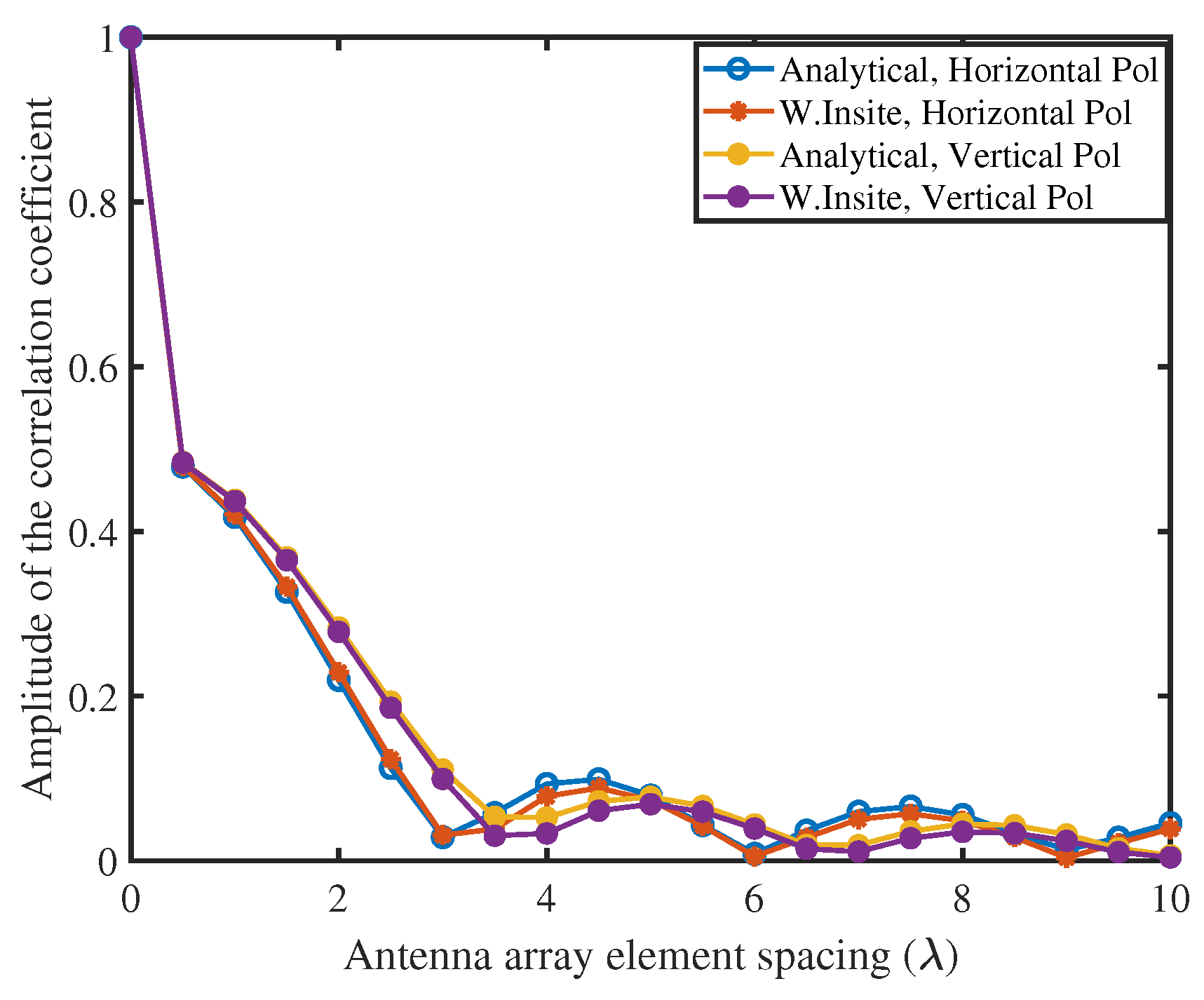
Figure 6.
Different measurement environments used for train-based communications in tunnel scenario.
Figure 6.
Different measurement environments used for train-based communications in tunnel scenario.
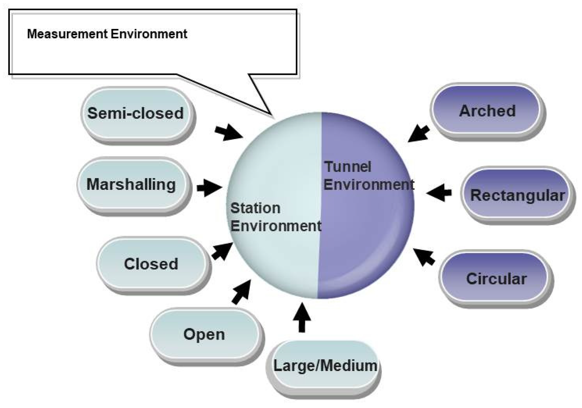
Figure 7.
The 100 m long Nantong tunnel inner view and geometry [45].
Figure 7.
The 100 m long Nantong tunnel inner view and geometry [45].
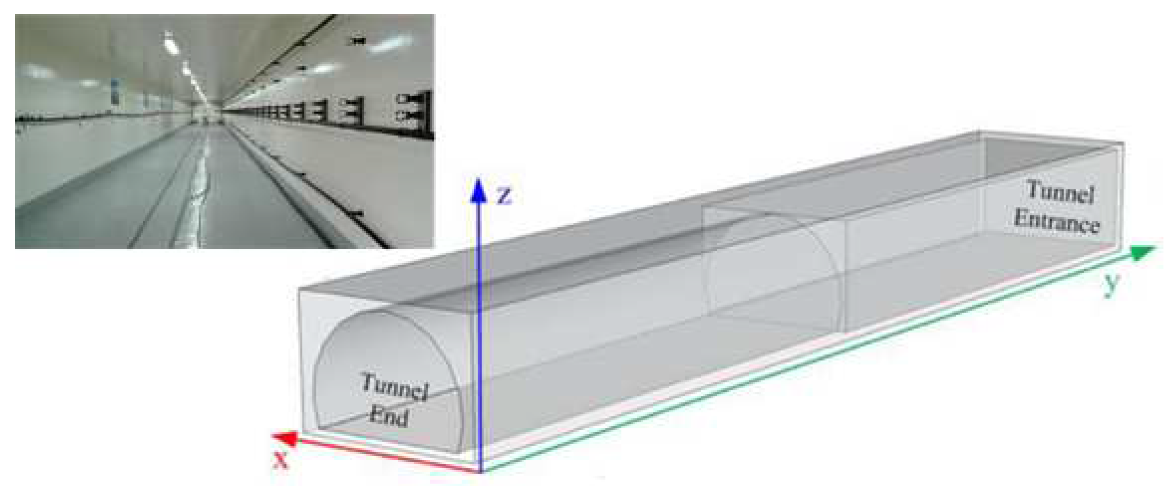
Figure 8.
Systematic architecture of parallel channel sounder for MIMO systems.
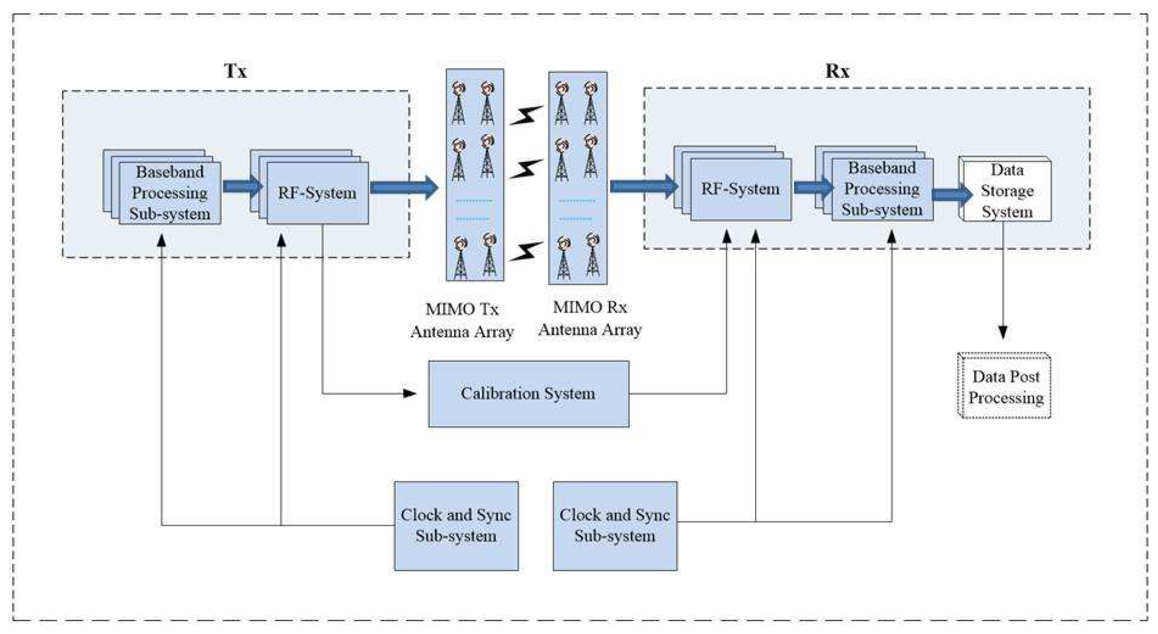
Figure 9.
The mobile movement along equivalent magnetic dipole or the leaky coaxial cable.
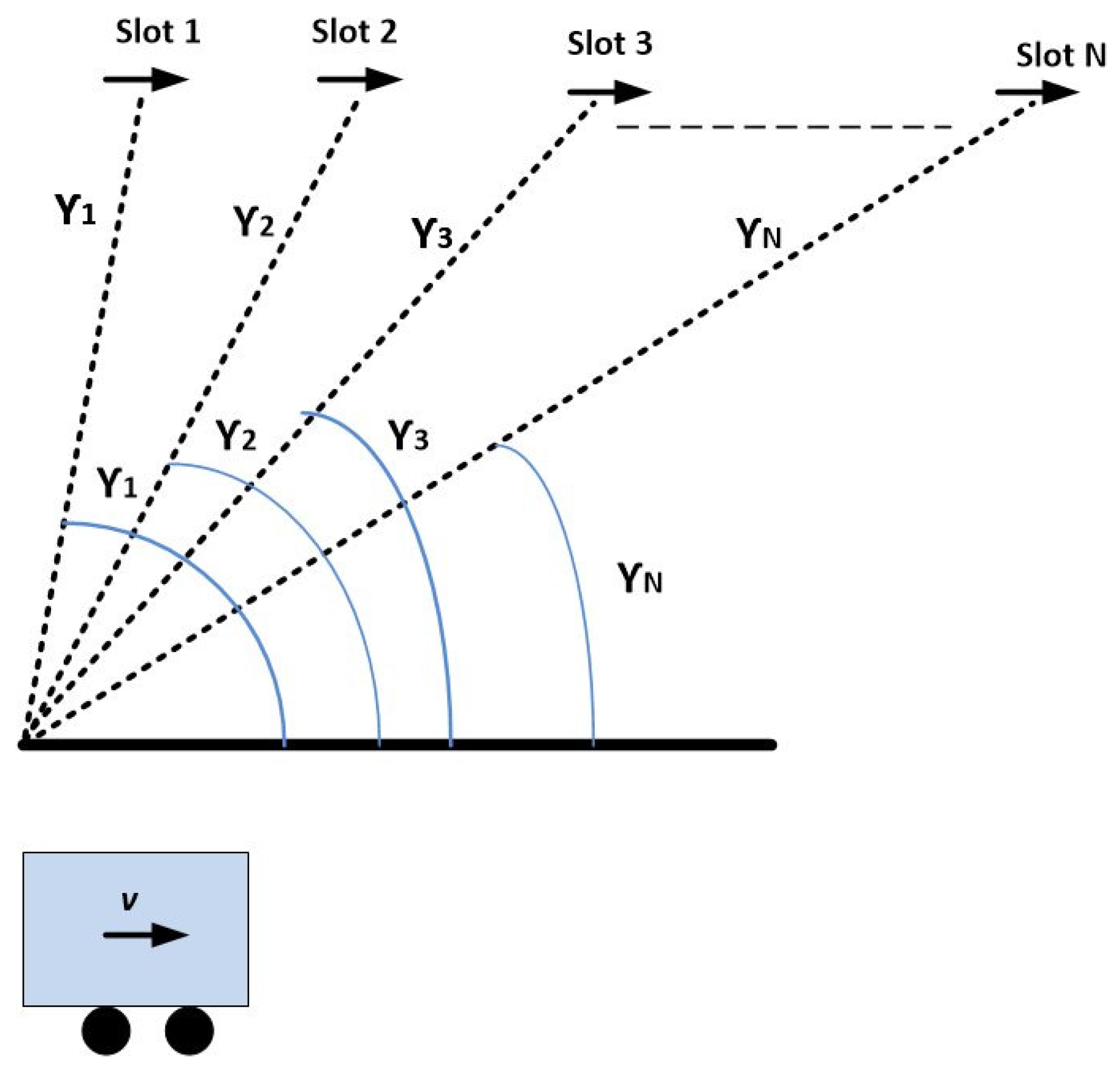
Figure 10.
Classification of different propagation models in tunnel environment.

Figure 11.
The flowchart of RIMAX Algorithm, deduced by [110].
Figure 11.
The flowchart of RIMAX Algorithm, deduced by [110].
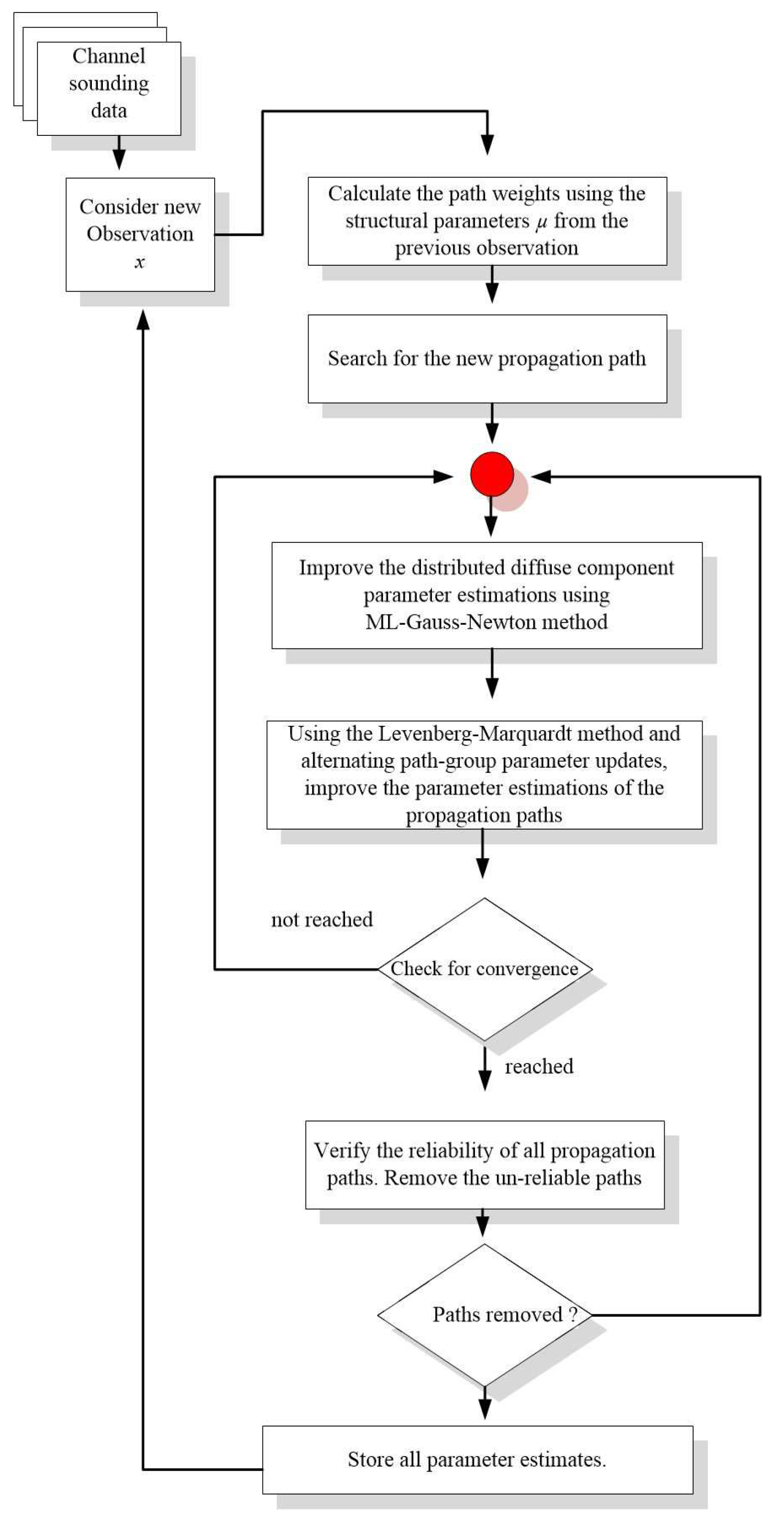
Figure 12.
A schematic diagram of small-scale and large-scale fading characteristics.
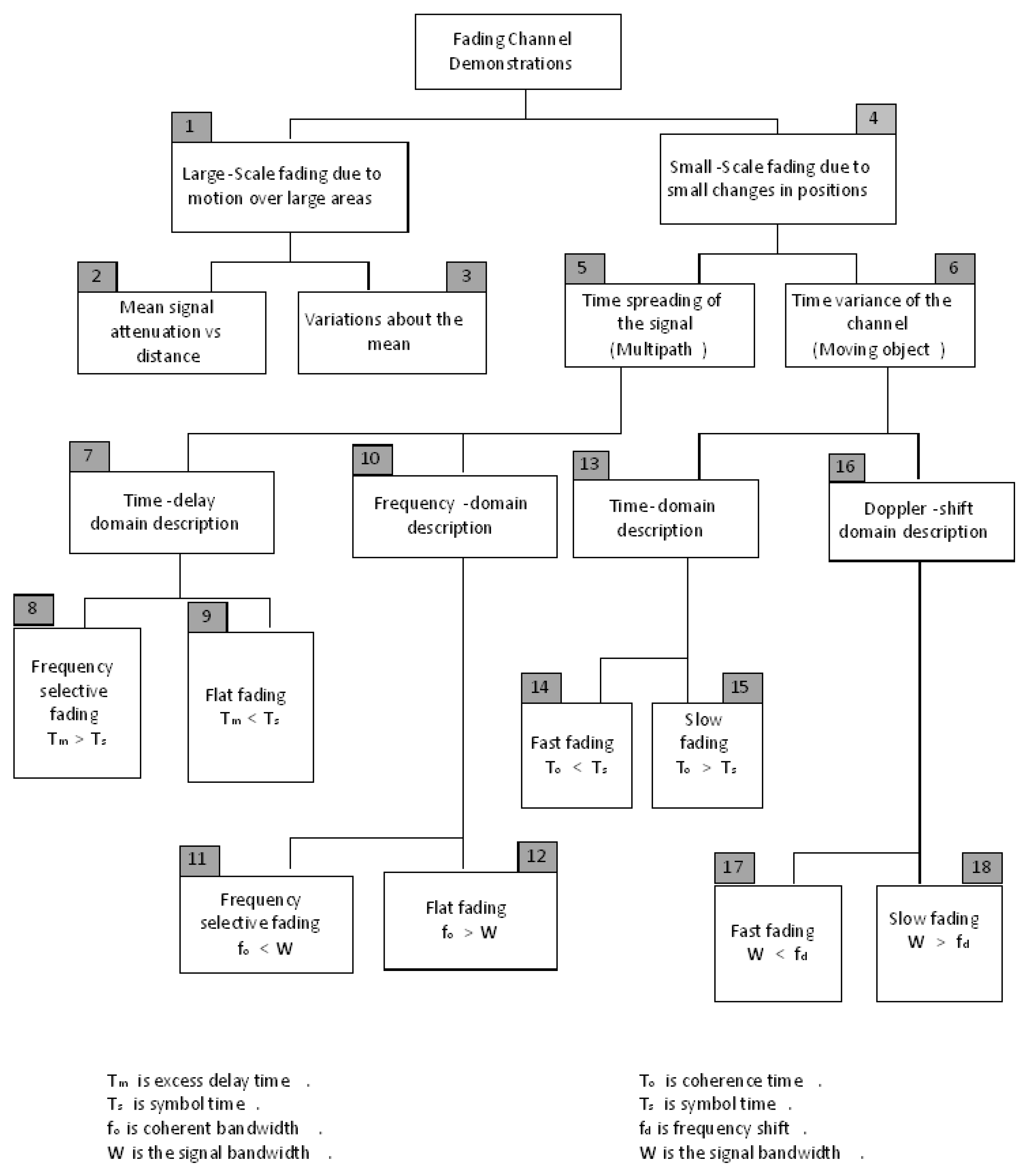
Figure 13.
IRS—based wireless communications. (a) Schematic diagram of V2V system in presence of IRS. (b) Zoomed—in image of the element shown in the inset together with an illustration of the digitally coded IRS surface. (c) The element’s phase and amplitude of its reflection spectra at different biasing voltages [125].
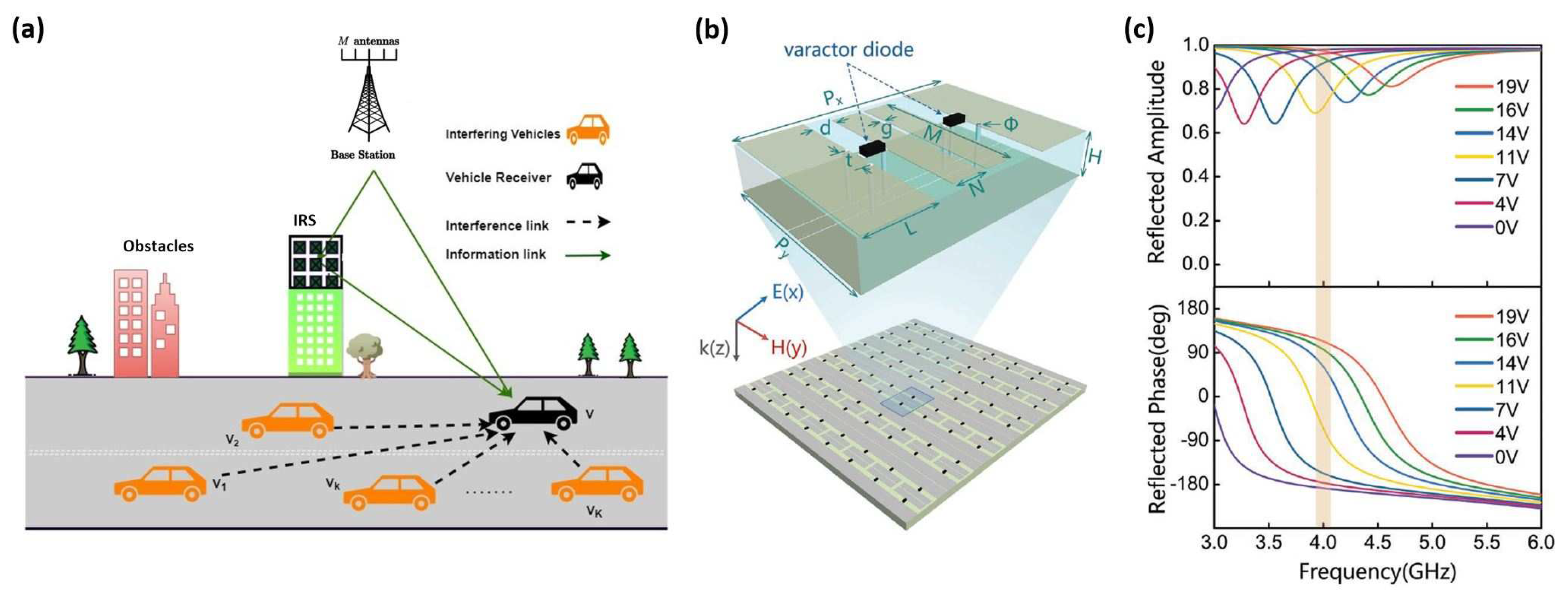
Figure 14.
Massive MIMO channel spatial characteristics in heterogeneous network.
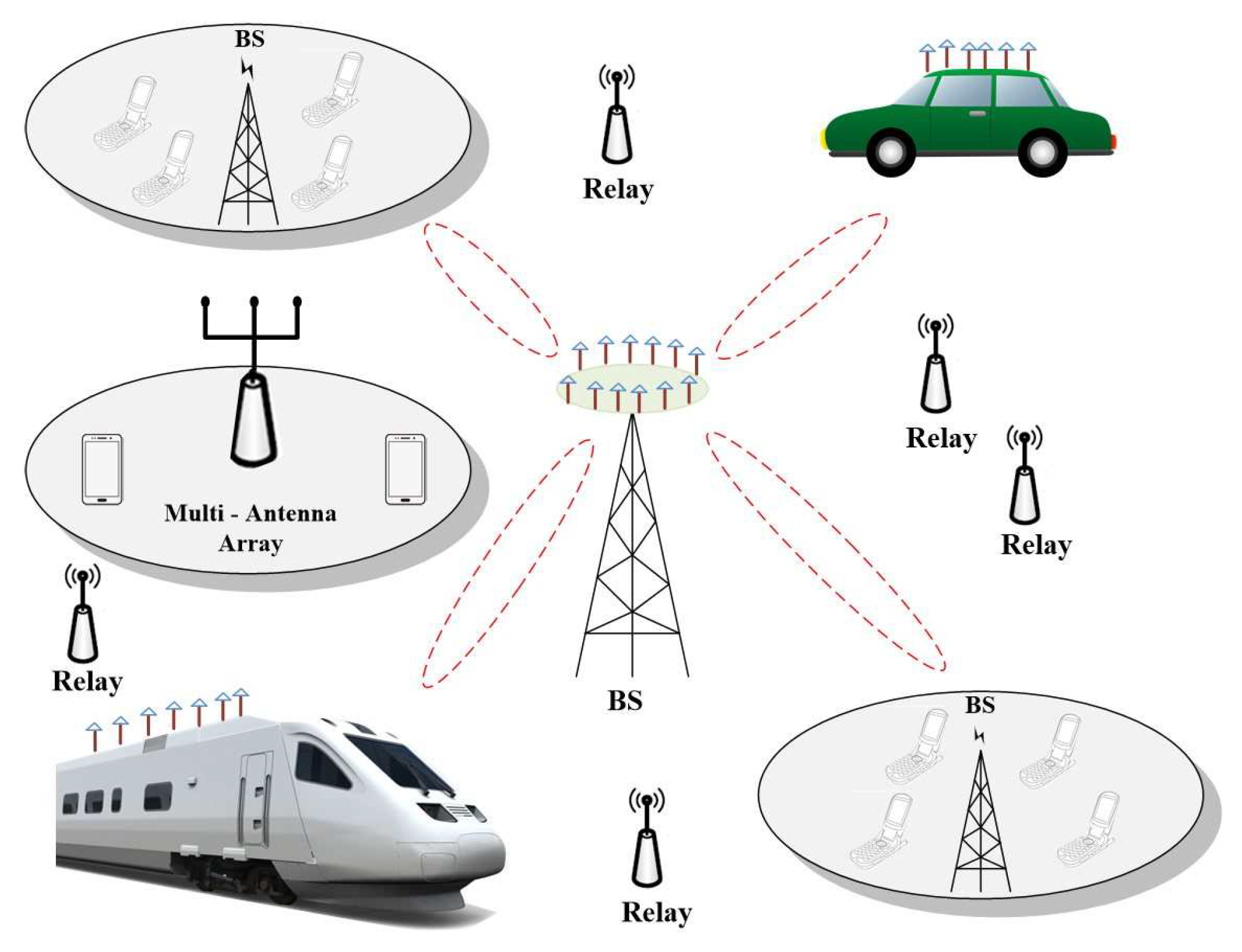
Figure 15.
The 2 × 2 and 4 × 4 MIMO channel capacities for various positions of antenna arrays [180].
Figure 15.
The 2 × 2 and 4 × 4 MIMO channel capacities for various positions of antenna arrays [180].
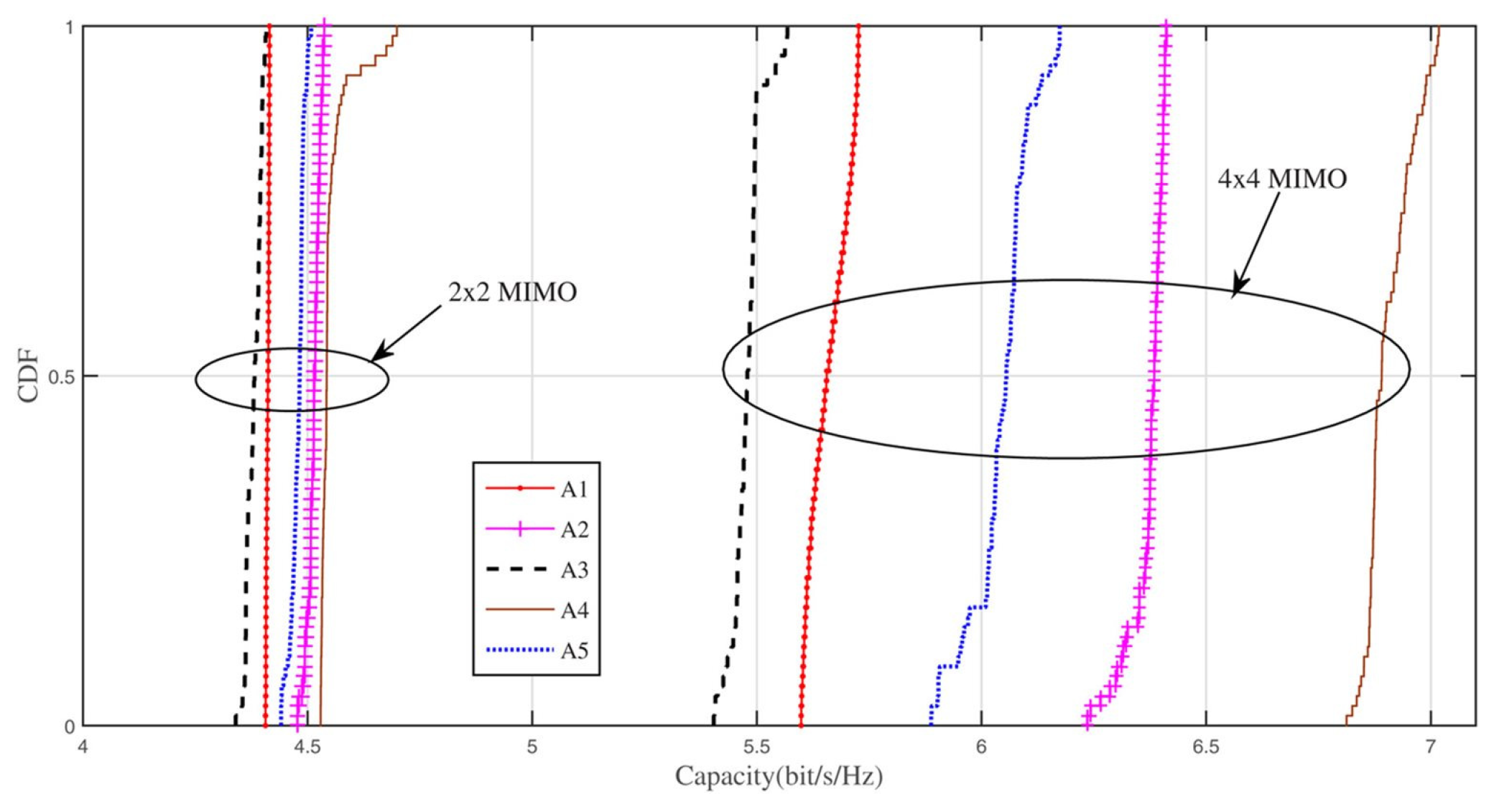

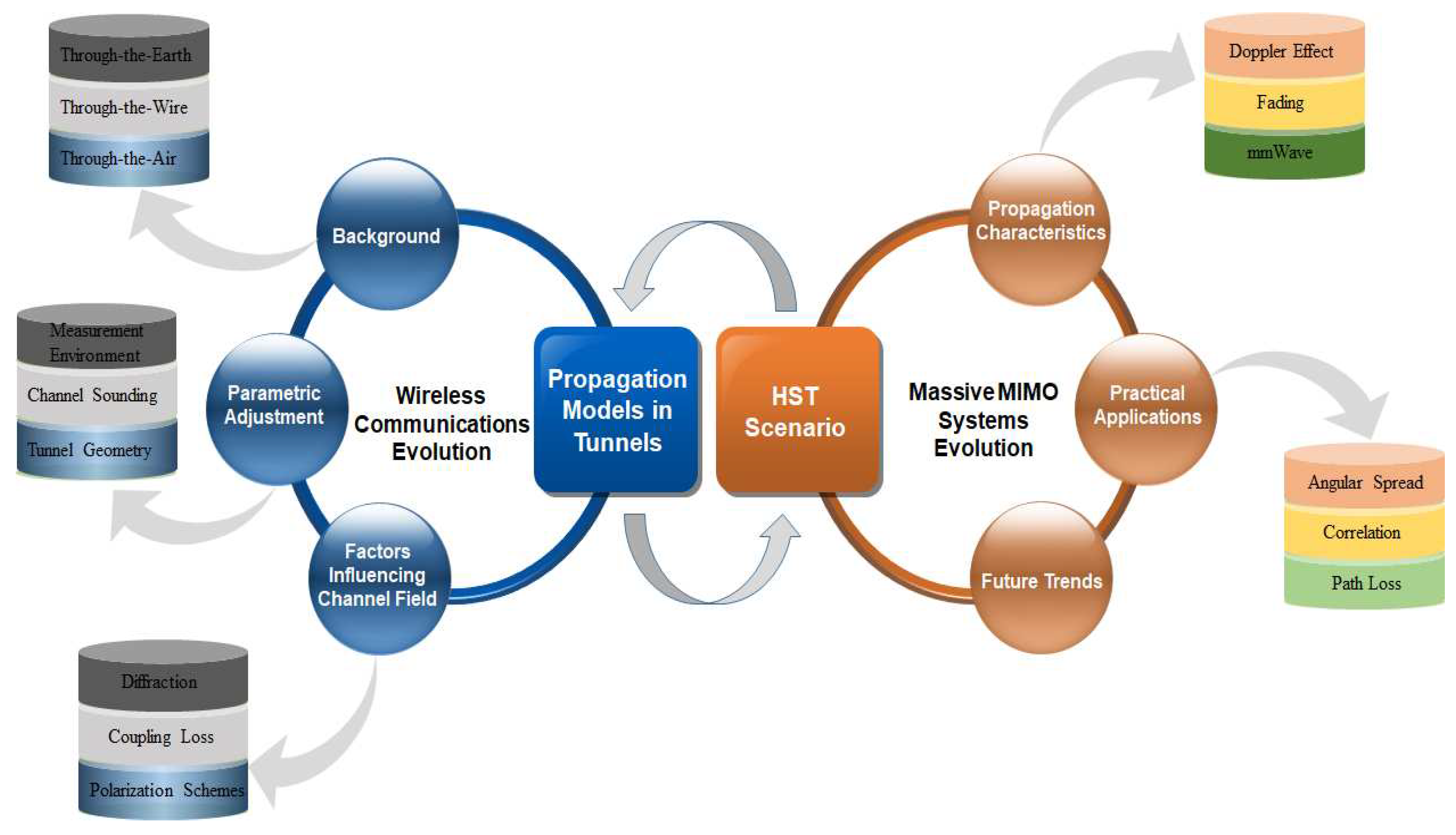
Table 1.
Glossary.
| Sr. No | Acronym | Full Name |
|---|---|---|
| 1 | AAoA | Azimuth Angle of Arrival |
| 2 | AAoD | Azimuth Angle of Departure |
| 3 | CBTC | Communication-Based Train Control |
| 4 | CL | Coupling Loss |
| 5 | CPML | Convolutional Perfectly Matched Layer |
| 6 | CDM | Code-Division Multiplexing |
| 7 | CSI | Channel Status Information |
| 8 | CFL | Courant–Friedrichs–Lewy |
| 9 | CAPEX | Capital Expenditure |
| 10 | DAS | Distributed Antenna System |
| 11 | DMCs | Dense Multipath Components |
| 12 | DPA | Dual Polarized Antenna |
| 13 | D2D | Device-to-Device |
| 14 | DSPN | Deterministic and Stochastic Petri Net |
| 15 | EAoA | Elevation Angle of Arrival |
| 16 | EAoD | Elevation Angle of Departure |
| 17 | ELF | Extremely Low Frequency |
| 18 | EoD | Elevation of Departure |
| 19 | ERTMS | European Railway Traffic Management System |
| 20 | EP | Equal Power |
| 21 | FDTD | Finite Difference Time Domain |
| 22 | FDM | Frequency-Division Multiplexing |
| 23 | FM | Frequency Modulation |
| 24 | GBSB | Geometrically-Based Single-Bounce |
| 25 | HSR | High-Speed Railway |
| 26 | HFSS | High-Frequency Structure Simulator |
| 27 | ISM | Industrial, Scientific, and Medical |
| 28 | IRS | Intelligent Reconfigurable Surface |
| 29 | LTE-M | Long-Term Evolution for Metro |
| 30 | LCX | Leaky Coaxial Cable |
| 31 | LAS | Likelihood Ascent Search |
| 32 | LSF | Large Scale Fading |
| 33 | LoS | Line of Sight |
| 34 | MIMO | Multi-Input Multi-Output |
| 35 | MMSE | Minimum Mean Squared Error |
| 36 | mmWave | MillimeterWave |
| 37 | NLoS | Non-Line of Sight |
| 38 | NFV | Network Function Virtualization |
| 39 | ODA | Omnidirectional Array |
| 40 | OPEX | Operational Expenditure |
| 41 | OFDM | Orthogonal Frequency-Division Multiplexing |
| 42 | PL | Path Loss |
| 43 | PAS | Power Azimuth Spectrum |
| 44 | PAP | Power Angular Profile |
| 45 | PDP | Power Delay Profile |
| 46 | PED | Personal Emergency Device |
| 47 | QoS | Quality of Service |
| 48 | RAT | Radio Access Technology |
| 49 | RF | Radio Frequency |
| 50 | SISO | Single-Input Single-Output |
| 51 | SD | Sphere Decoding |
| 52 | SIC | Soft Interference Cancellation |
| 53 | SMCs | Specular Multipath Components |
| 54 | STF | Space–Time Frequency |
| 55 | SDN | Software Defined Networking |
| 56 | TDM | Time-Division-Multiplexing |
| 57 | TTA | Through-the-Air |
| 58 | TTE | Through-the-Earth |
| 59 | TTW | Through-the-Wire |
| 60 | TS | Tabu Search |
| 61 | TCF | Temporal Correlation Function |
| 62 | UAV | Unmanned Aerial Vehicle |
| 63 | UCA | Uniform Cylindrical Array |
| 64 | ULA | Uniform Linear Array |
| 65 | UHF | Ultra-High Frequency |
| 66 | UPA | Uniform-Planar Array |
| 67 | VHF | Very High Frequency |
| 68 | VHFFM | Very High Frequency-Frequency Modulation |
| 69 | VPE | Vector Parabolic Equation |
| 70 | WLAN | Wireless Local Area Network |
| 71 | WSN | Wireless Sensor Network |
| 72 | WPAN | Wireless Personal Area Network |
| 73 | XPD | Cross-Polarization Discrimination |
Table 2.
Path-loss exponent for different tunnel environments and antenna constraints.
| Environment Dimensions in Meter | Measurement Frequency | Antenna Polarization | Antenna Configuration | Antenna Bandwidth | Scenarios | Path Loss Exponent | Ref. | ||
|---|---|---|---|---|---|---|---|---|---|
| Free Space | — | — | — | — | — | 2 | [67] | ||
| In Building, LoS | 1.6–1.8 | ||||||||
| In Building, Obstructed | 4–6 | ||||||||
| Straight Tunnel | 7.5 × 4 × 2000 | 900 MHz | Linear | SISO | Omni-directional | LoS | 3.87–4.44 | [68] | |
| 7 × 3.7 × 120 | 2.9–3.7 | ||||||||
| 4.2 × 3 × 10,000 | 1.87–2.37 | ||||||||
| Straight Tunnel (3.34 × 2.6 × 259) | 900 MHz | Linear | SISO | Omni-directional | LoS | 4.2–4.49 | [68] | ||
| 1.8 GHz | 2.12–2.46 | ||||||||
| CANMET Level 70 m (2.5 × 4 × 70) | 2.3–2.5 GHz | Linear | SISO | Omni-directional | LoS | 2.03 | [69,70] | ||
| NLoS | 4.62 | ||||||||
| 5.7–5.9 GHz | LoS | 2.22 | |||||||
| NLoS | 3.52 | ||||||||
| CANMET Level 40 m (5 × 5 × 75) | 2.3–2.5 GHz | Linear | SISO | Omni-directional | LoS | 2.13–2.33 | [71] | ||
| NLoS | |||||||||
| CANMET Level 40 m (4 × 5 × 8) | 57.24–59.4 GHz | Linear | SISO | Horn–Horn | Omni-directional and Horn | LoS | 1.82 | [72] | |
| Omni–Horn | 1.28 | ||||||||
| CANMET Level 70 m (2.5 × 4 × 8) | Horn–Horn | 1.45 | |||||||
| Omni–Horn | 1.41 | ||||||||
| CANMET Level 70 m (2.5 × 4 × 10) | 3–10 GHz | Linear | SISO | Omni-directional | LoS | 2.11 | [73] | ||
| NLoS | 3.00 | ||||||||
| Directional | LoS | 2.01 | |||||||
| NLoS | 6.16 | ||||||||
| CANMET Level 40 m (5 × 5 × 25) | 2.3–2.5 GHz | Linear | 2 × 2 MIMO | Directional Patch | LoS | 1.73 | [73] | ||
| NLoS | 3.03 | ||||||||
| CANMET Level 4 m (5 × 5 × 10) | 57–64 GHz | Linear | 2 × 2 MIMO Patch | Directional | LoS | 1.48 | [74] | ||
| NLoS | 2.40 | ||||||||
| CANMET Level 70 m (2.5 × 4 × 10) | 5.7–5.9 GHz | Linear | 2 × 2 MIMO | Vivaldi | LoS | 2.1 | [75] | ||
| CANMET Level 40 m (3.4 × 4.6 × 30) | 2.35–2.55 GHz | Linear | 4 × 4 MIMO CMPA | Directional | LoS | 1.18 | [76] | ||
| NLoS | 2.56 | ||||||||
| 4 × 4 MIMO PMPA | LoS | 1.29 | |||||||
| NLoS | 3.8 | ||||||||
Table 3.
Recent research based on ray tracing in tunnel environment.
| Carrier Frequency | Tunnel Type | Research Method | Main Content | Ref. |
|---|---|---|---|---|
| 400 MHz | Rectangular concrete subway tunnel | Ray Tracing | FDTD method was used to estimate the path gain | [96] |
| 900 MHz | Straight rectangular tunnel | Ray Tracing | RMS-DS for vertically and horizontally receiving antennas | [97] |
| 28 GHz | Nantong subway tunnel | Ray Tracing | MIMO system performance under LoS condition | [98] |
| 25 GHz | Subway tunnel, Line 8 in Seoul, Korea | Use of ray tracing after comparing with measurement results | Study the millimeter wave, propagation characteristics of straight tunnels and curved tunnels, like PL, AoA, AoD by ray tracing | [99,100] |
| 32.5 GHz | Subway tunnel in Korea | Ray Tracing | Study the PL and Shadowing fading under arched tunnel environment by ray tracing | [101] |
| 24 GHz | Subway tunnel | Ray Tracing | Study the effect of tunnel structure and roughness on millimeter wave propagation | [102] |
| 32.5 GHz | High-speed train tunnel | Ray Tracing | Study the propagation characteristics under arched tunnel environment by ray tracing | [62,103] |
| 60 GHz | Highway tunnel | Ray Tracing | Study the effect of vehicles of on millimeter wave propagation by ray tracing | [104] |
| 75 GHz | Railway tunnel | Ray Tracing | PL and RMS-DS | [101] |
| 38 GHz | Shanghai subway tunnel, Line 9 | Ray Tracing | PL, RMS-DS of straight and curved tunnels | [105,106] |
Table 4.
Validation of recent works using IRS elements.
| Communication Networks | Design Parameters | Aims | Applications | Limitations | Ref. |
|---|---|---|---|---|---|
| Multi-Stream MIMO | IRS elements and the transmitted signal’s covariance matrix | Improvement in feasible rate | Gradient Method | Smaller IRS unit cells and indoor communications | [126] |
| MISO | Beamforming at ITS and BS | Minimize transmitted power | Particle swarm optimization algorithm | Improve SNR without CSI knowledge | [127] |
| Single-User MIMO | Optimization of IRS elements | Rank improvement | Water-filling algorithm | Power allocation and LoS scenario | [128] |
| Downlink THz-MIMO | Pre-coded and phase shift matrix of IRS | Spectral efficiency | Cross entropy, water filling, and SVD models | Substantial transmission loss | [129] |
| Downlink multi-user MISO-mmWave | Phase shift matrix of IRS and transmitted power | Improve energy efficiency and sum-rate | Sequential fractional programming | Smaller outage and coverage probability | [130] |
| IRS-based ITS | Array reflector of the Van-Atta type | QoS and RF sensing | REITS method | Increased mobility | [131] |
| Multi-antenna system | Spectral phase shift and source transmitted covariance | Strengthen secrecy | Optimization at the variable-level | Source transmitted power | [132] |
| IRS-based vehicular | IRS-based resources allocation | Probability of secrecy outage | IRS as receiving antenna in V2I and relay for V2V scenario | High number of IRS elements | [133] |
| Vehicular network | IEEE 802.11p transmission samples | Received signal power and channel prediction | Deep learning method | Various environments | [134] |
| IRS for communications with UAVs | OFDMA networks | Optimized sum-rate | Variable-level optimization | Phase shift of IRS | [135] |
Table 5.
Different channel models for HST in tunnel environment.
| Channel Model | Operating Frequency | Antenna Configuration | Scenario | Channel Characteristics | Ref. |
|---|---|---|---|---|---|
| Multimode model | 450 MHz, 900 MHz | SISO | Rectangular subway tunnel | PDP, Field distribution | [140] |
| GBSB model | 900 MHz | MIMO | Rectangular tunnel | Rice factor, PDP, Correlation function of space-time | [141] |
| Path loss model | 2.4 GHz, 5 GHz | SISO | Subway tunnel | RMS-DS, PL, Channel capacity, Channel stationarity | [142] |
| WINNER model | 5.8 GHz | MIMO | Subway tunnel | AoA, AoD, PL, Delays, Fast fading | [143] |
| Deterministic Physics-based UWB | 5.8 GHz | SISO | Rectangular tunnel | CIR, RMS-DS, Received power | [144] |
| Multimode waveguide | 2.4 GHz | MIMO | Underground mine, Subway tunnel | PAS, Correlation, Angular properties | [145] |
| Theory of propagation-graph | 1.8 GHz | MIMO | Arched tunnel | Channel capacity, Correlation coefficient, CIR, Channel coefficients | [146] |
| Geometrical optics model | 900 MHz | SISO | Underground mine | SSF,LSF | [147] |
| FSMM | 2.412 GHz | SISO | Subway tunnel | SNR, Distance interval, States number | [148] |
| Propagation model | 2.4 GHz | SISO | Subway tunnel | Fast fading, PL, SF, AFD, LCF | [149] |
| Bartlett model | 3.5 GHz | MIMO | Subway tunnel | PDP. Angular spread, Condition number | [150] |
| Path loss model | 2.49–4 GHz | MIMO | Rectangular tunnel | Delay spread, PL | [151] |
Table 6.
A brief overview of massive MIMO channel characteristics in underground tunnels.
| Channel Sounder | Scenario | Antenna Array Configuration | Carrier Frequency | Channel Characteristics | Ref. |
|---|---|---|---|---|---|
| RUSK-Hyeff | O2I | Tx ULA/Rx DPA (16 × 24)Tx ULA/Rx DPA(16 × 24) Tx ULA/Rx DPA (16 × 24) | 2.53 GHz | Capacity, elevations, angles, AS Capacity, elevations, angles, AS Capacity, elevations, angles, AS | [171] |
| PropSound CS | O2I, outdoor | Tx UPA/Rx ODA (32 × 56) Tx UPA/Rx ODA(32 × 56) Tx UPA/Rx ODA (32 × 56) | 3.5 GHz | Capacity, spatial correlation, eigenvalues, AS, PAS | [172] |
| 1lVNA and RUSK-LUND | Outdoor | Tx UCA and ULA (64 and 128) Tx UCA and ULA(64 and 128) Tx UCA and ULA (64 and 128) | 2.6 GHz | Capacity, SVS | [173] |
| PropSound CS | O2I, outdoor | Tx UPA/Rx ODA (256 × 16) Tx UPA/Rx ODA(256 × 16) Tx UPA/Rx ODA (256 × 16) | 3.5, 6 GHz | PDP, AS, PAS, eigenvalue spread, capacity | [174] |
| VNA | Indoor | Tx Horn /Rx Biconical (51 × 51, 76 × 76, 91 × 91, 121 × 121) | 11, 16, 28, 38 GHz | DS, Power, AS, AoA, EoA, spatial correlation | [175] |
| VNA | Outdoor | Tx ULA (128) | 2.6 GHz | K-factor, spatial correlation, power, PAS, eigenvalue | [176] |
| 1lMedav sliding-correlator | Indoor | Tx ODA/Rx UPA (1 × 121) Tx ODA/Rx UPA(1 × 121) Tx ODA/Rx UPA (1 × 121) | 9.5 GHz | AoD, AoA, EoA, EoD | [177] |
| Constructed | Outdoor | Tx ULA/Rx ULA (144 × 144) Tx ULA/Rx ULA(144 × 144) Tx ULA/Rx ULA (144 × 144) | 1.4725 GHz | Path loss, PAS | [178] |
| VNA | Indoor | Tx ODA/Rx UPA (1 × 1600) Tx ODA/Rx UPA(1 × 1600) Tx ODA/Rx UPA (1 × 1600) | 15 GHz | K-factor, AOA, power, AS, cluster number, EoA | [179] |
Disclaimer/Publisher’s Note: The statements, opinions and data contained in all publications are solely those of the individual author(s) and contributor(s) and not of MDPI and/or the editor(s). MDPI and/or the editor(s) disclaim responsibility for any injury to people or property resulting from any ideas, methods, instructions or products referred to in the content. |
© 2023 by the authors. Licensee MDPI, Basel, Switzerland. This article is an open access article distributed under the terms and conditions of the Creative Commons Attribution (CC BY) license (https://creativecommons.org/licenses/by/4.0/).
Share and Cite
MDPI and ACS Style
Saleem, A.; Zhang, X.; Xu, Y.; Albalawi, U.A.; Younes, O.S. A Critical Review on Channel Modeling: Implementations, Challenges and Applications. Electronics 2023, 12, 2014. https://doi.org/10.3390/electronics12092014
AMA Style
Saleem A, Zhang X, Xu Y, Albalawi UA, Younes OS. A Critical Review on Channel Modeling: Implementations, Challenges and Applications. Electronics. 2023; 12(9):2014. https://doi.org/10.3390/electronics12092014
Chicago/Turabian StyleSaleem, Asad, Xingqi Zhang, Yan Xu, Umar A. Albalawi, and Osama S. Younes. 2023. "A Critical Review on Channel Modeling: Implementations, Challenges and Applications" Electronics 12, no. 9: 2014. https://doi.org/10.3390/electronics12092014
Note that from the first issue of 2016, this journal uses article numbers instead of page numbers. See further details here.