Abstract
This paper proposes an enhanced transport layer protocol for precise flow control in data centers, referred to as PFDCT, combining explicit rate control (priority scheduling) and implicit rate control (marking algorithm with dynamic threshold) innovatively, while satisfying the transmission requirements of each data flow. It enables multiple data flows to share the bandwidth fairly, which is rarely achieved by previous data transmission protocols. Our design stems from the observation that different packets in a data center network need to be processed differentially and that the accuracy of the feedback of the indication information to the link state will directly affect the effectiveness of the congestion control mechanism. Our tests show that PFDCT has lower network jitter, better fairness, and significant performance gains over existing proposals (DCTCP, ICTCP, and L2DCT) in terms of Flow Completion Time (FCT) and throughput on average. Furthermore, we discussed the impact of the marking algorithm with dynamic thresholds on the performance of PFDCT, and the results of the experiments show that the addition of the marking algorithm will further improve the performance of PFDCT in terms of packet loss rate, latency, and FCT.
1. Introduction
Data center networks (DCNs) use centralized infrastructures to provide users with diverse network services and large-scale data computing, such as video streaming and cloud computing. A data center network has several characteristics that make it different from the Internet or Local Area Networks (LANs). First of all, data center networks are specially designed for data-intensive communications. It can provide users with large-scale computing services such as network storage, email, and web search. These computing services have a great impact on the transmission bandwidth between distributed components in the network. Higher requirements were put forward. Secondly, there are thousands of densely interconnected servers in the data center, and its hardware scale is much larger than the general LAN infrastructure. How to flexibly manage the communication between servers is also a challenge.
Aggregator applications in data centers, such as web search or MapReduce, often request data from thousands of servers simultaneously, leading to a many-to-one traffic situation. In this case, numerous workers simultaneously establish Transmission Control Protocol (TCP) connections with the aggregation application and transmit the data requested by the application back to the aggregator, causing a large amount of traffic data to be aggregated suddenly to the bottleneck switch. Even worse, bottleneck switches often have very shallow buffers. Therefore, most concurrent TCP connections will inevitably lose a large number of data packets, and in severe cases, multiple TCP timeouts will occur, resulting in a serious drop in network throughput and greatly prolonged data transmission completion time. Researchers refer to this catastrophic network throughput collapse caused by many-to-one concurrent connections as TCP incast [1]. With the explosive emergence of many-to-one aggregator applications in today’s data centers, the TCP incast problem is becoming one of the most serious problems affecting the quality of service of data centers.
The most obvious and serious impact of TCP incast on the data center network is packet loss and even timeout. As shown in Figure 1, For each query, the application in data center network retrieves data from a number of servers. The query cannot complete until responses are received from all servers. However, it is well known that foreground applications generate mostly short flows (for example, 1 KB to 10 KB) [2,3], while background applications generate mostly long flows (for example, 1 MB to 100 MB), which are sensitive to network throughput [4,5]. In other words, once TCP incast causes data block loss, the transmission of short flows cannot meet the delay requirement, and the throughput of long flows will be seriously affected as the query cannot be completed.
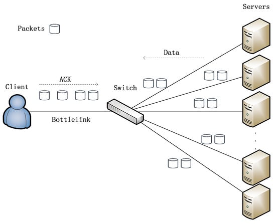
Figure 1.
TCP incast scenario.
A mass of mechanisms and protocols have recently been proposed to solve the data congestion problem caused by the TCP incast problem; however, these schemes usually focus on only one dimension of the complex problem space, ignoring the need for different idiosyncratic flows to be controlled by different data transfer strategies. For example, DCN algorithm [6] only controls long flows, while T-RACKs [7] and CWND [8] focus on improving Flow Completion Time (FCT) of small flows to ensure short FCT of short flows. Other approaches [9,10] do provide excellent performance for long flows but perform poorly for short flows [11,12].
To ensure the transmission of both long and short flows without sacrificing another, we proposed a novel flow-aware and delay-based transport layer protocol for data centers, PFDCT (Transport Layer Protocol for Precise Flow Control in Data Centers). PFDCT utilizes the end-to-end delay, Explicit Congestion Notification (ECN) [13] marking and the characteristics of flows to jointly improve the service quality of the data center network. The main contributions of PFDCT are:
- In order to provide long-term stable throughput for the link, PFDCT only performs ECN marking on long flows, and PFDCT optimizes the traditional ECN fixed marking threshold to a traffic-aware dynamic marking threshold to cope with complex and frequently changing data center network environments.
- PFDCT has developed a priority-based queue management mechanism according to the urgency of data packet transmission, data transfer rate, and data flow size. It simultaneously guarantees the transmission quality of long-flow packets, short-flow packets, and retransmission packets, which constitute almost all traffic in the data center network. The above measures make the ECN marking algorithm of PFDCT more fair and efficient during data transfer.
- Considering the complexity of the model and measurement accuracy, PFDCT combines two kinds of feedback information, the readily available Round-Trip Time (RTT) from the network and the widely supported ECN marking, to obtain the most accurate link status while saving link overhead. The above measures can ensure that the work of PFDCT is more reasonable and efficient.
- We tested the performance of the PFDCT protocol in terms of end-to-end delay, flow completion time, and packet loss rate, and compared it with the scheme under the fixed threshold, finding that the above indicators of PFDCT are better than the fixed-threshold one to varying degrees. Extensive evaluations showed that PFDCT performs much better on FCT compared to DCTCP, ICTCP, and L2DCT in the simple-scale topology. For a link load of 100%, the throughput of PFDCT is 0.41 MB higher than that of L2DCT, which is better than other similar schemes. In the large-scale topology, PFDCT also maintains a steady increase in throughput, with a stable fairness index of 0.55, which is more than 20% higher than ICTCP.
The rest of the paper is organized as follows: Section 2 summarizes the related work to solve the TCP incast problem. Section 3 describes PFDCT in detail. Section 4 analyzes the changes brought by the dynamic-threshold-based ECN marking algorithm to PFDCT. Section 5 presents the implementation of PFDCT and analyzes the performance evaluation. Section 6 concludes the paper.
2. Related Work
Several schemes are proposed to deal with the incast problem in data center networks and we will present some of the most widely known schemes and their corresponding limitations below. To carry out accurate positioning, evaluation, and analysis of the existing scheme, and also make the writing more fluent, we divided the solutions to TCP incast in data center networks into the transport layer solutions and the non-transport layer solutions. We will first introduce the typical schemes of the non-transport layer below.
The scheme of the non-transport layer is mainly to solve the TCP incast problem from the perspectives of the data link layer and the application layer. Quantized Congestion Notification (QCN) [14] and its variants are typical congestion control mechanisms implemented at the link layer. The QCN scheme consists of two parts, one is the congestion point (CP) dynamics and the other is the reaction point (RP) dynamics. The CP’s switch buffer samples incoming packets to determine the source of congestion, and the RP adjusts the sending rate after receiving congestion feedback information. Since most data flows causing TCP incast are transmitted synchronously, QCN does not perform well in many-to-one transmission scenarios. Prajjwal Devkota et al. [3] improved the QCN scheme and attributed the QCN performance degradation to flow variability. They employed adaptive sampling at the switch and traffic adaptive approach at the rate limiter to improve the performance of the scheme in the TCP incast scenario. Unlike the above solutions, application layer solutions always use the method of modifying the end host to avoid incast. CCMA [15] is a concurrent connection management agent for incast mitigation, it is an application-layer agent on the receiver side that manages concurrent TCP connections on behalf of the aggregated application. For multiple co-existing aggregators, CCMA schedules them sequentially to avoid traffic collisions. DSRAL [16], ARS [10], and PICC [17] avoid TCP incast by controlling the number of concurrent TCP connections. However, these methods all assume that the receiver is aware of the remaining available bandwidth, which is usually not valid in real data centers. Since DSRAL (and [10,15,16]) is built into each aggregator application, it inherently cannot control traffic congestion caused by multiple concurrent senders connected to the same receiver.
In the transport layer schemes, a lot of work tries to solve the incast problem by adjusting TCP parameters. For instance, AP [18] uses pacing to change the sending interval. Swift [19] uses the Additive Increase Multiplicative Decrease (AIMD) algorithm to control end-to-end delay, and uses pacing to control packet sending interval in the case of extreme network congestion. Similarly, Packet Slicing [20] enables packet slice to mitigate packet loss and throughput degradation caused by traffic bursts. These methods make it easier to trigger the network’s fast retransmission mechanism rather than Retransmission TimeOut (RTO). Other solution, e.g., CP [21] tries to reduce retransmission latency by reducing (200 ms by default) to the same timescale as network latency. However, these solutions may lead to premature and unnecessary retransmissions, which in turn trigger more timeout events. Especially when the number of TCP concurrency is large [20], the probability of TCP incast does not decrease.
The ECN mechanism improves and extends the TCP/IP protocol, so that the network can enable the terminal to obtain link information without using packet loss as a congestion feedback signal. In DCNs, commodity switches make the ECN marking decision as packets are dequeued. ECN relies on active queue management (AQM) schemes such as Random Early Detection (RED) [22] to track queue changes at bottleneck switches. When the queue length of the switch buffer exceeds the preset threshold, ECN will mark the Congestion Experienced (CE) bit in the Internet Protocol (IP) header, thereby notifying the terminal to adjust the data sending rate. Once an endpoint observes that a packet has experienced congestion, the sender reduces the transmission rate (the window is halved).
Alizadeh et al. identified the user’s demand for DCN transmission, and indicated that the early ECN solution could not provide high-performance services for the data center. In data centers, the number of background flows is small (e.g., 2 or 3) and their congestion windows tend to be synchronized. Additionally, most traffic is considered to be bursty in nature. Therefore, the behavior of the ECN feedback mechanism to halve the congestion window when the link is likely to be congested will cause severe jitter instead of gracefully converging to the available bandwidth [23]. To sum up, 1-bit ECN feedback can only indicate link congestion, but not the degree of network congestion.
In order to achieve fine-grained congestion window adjustment, DCTCP marks packets using the instantaneous queue length and the ECN marking threshold K of a single queue, which be maintained independently for other queues. DCTCP uses the packet marking mechanism of ECN to obtain link feedback. At the same time, considering the limitations of standard ECN, DCTCP adopts a simpler active queue management scheme. It ensures that once the occupancy of the queue exceeds a fixed threshold K, the switch can mark subsequent arriving packets with a CE code point. In order to notify the sender that it is experiencing congestion in a timely manner, DCTCP sends an acknowledgment (ACK) for each packet and communicates back to the sender the exact sequence number of that packet. The ECN-Echo flag is set if and only if the packet has a marked CE codepoint. Through these changes, DCTCP greatly improves the throughput of data center networks, and DCTCP and ECN-based window control schemes have received great attention for their good applicability and performance [24].
Many solutions also try to solve TCP incast problems by changing the ECN tag threshold, changing the position of the ECN marks, and solving the buffer overflow problem caused by microbursts. CEDM [25] merged enqueue and dequeue ECN marks, A-ECN [26] adjusted the packet marking threshold as packets arrive to accommodate multi-queue conditions in the data center network. However, these methods barely avoid timeout upon heavy incast, since in this case packet loss is so massive and bursty that TCP usually receives no ACK at all (i.e., full window loss) [18,20,27]. RTT in traditional TCP/IP networks differs by several orders of magnitude from the block transfer time in data center networks, which means that RTT in traditional IP networks is no longer suitable for data center networks with high latency requirements. To this end, RAPID [28], T-Racks [29], and TCP-EFR [30] have focused on improving the fast retransmission/fast recovery mechanism in traditional networks, starting with repeated ACK, to avoid triggering RTO in the event of congestion and optimize short-flow FCT in response to congestion.
Whether a solution is deployed at the transport or non-transport layer, more and more attention has been paid to the use of packet priority in recent years. PRIN [31] established a model to analyze the causes of the TCP incast phenomenon and reduced the flow completion time of short flows by improving the priority of the last three packets at the end of the block. RAPID [28] assigned a higher priority to retransmission packets to solve the packet loss problem during data retransmission. PTCP [32] calculated the priority of packets based on the size and expiration date of traffic, and then the priority is used to adjust the receiving window and control ACK interval time to minimize the FCT.
To make up for the shortcomings of the above schemes and complement the priority-based schemes, we propose PFDCT. Based on the flow characteristics, PFDCT uses RTT as congestion feedback, which is a congestion control mechanism similar to DCTCP [33]. PFDCT configures different priorities for packets based on the urgency of their delivery. In particular, retransmitted packets are given the highest priority to avoid triggering the RTO mechanism. Once packets overflow from the switch’s shallow buffer and are lost, PFDCT will do its best to complete the delivery of retransmitted packets as quickly as possible. The most significant difference from the above schemes is that PFDCT considers each type of packet (long-flow packet, short-flow packet, and retransmission packet) most commonly seen in the data center, balancing the transmission of each flow and never sacrificing one flow to any other. PFDCT combines the switch-side control with the sender-side control and adjusts the ECN marking threshold dynamically to adapt to the rapidly changing network environment by obtaining the queue length through RTT.
3. PFDCT Design
The design of the PFDCT is presented in this section. The first part introduces the basic idea of the PFDCT protocol, and the second part gives the design details of the protocol. The packet type of PFDCT and the adopted switch model are defined in the latter part. In the end all the algorithms of PFDCT are described, including how to assign priority to all packets, update the ECN marking threshold and adjust the congestion window.
3.1. Basic Idea
DCN supports various applications with complex flow structures. To allocate network resources more reasonably and improve network service quality, PFDCT requires differentiated control on different traffic and uses a more comprehensive, fairer, and more efficient transmission control mechanism to meet the transmission requirements of different traffic. The idea of PFDCT is that the sender will record the size of each flow at the beginning and will configure different priorities for the packets based on the urgency of delivery and the packet size. Only for long flows does PFDCT enable the ECN marking algorithm. Next, by calculating the queue length of the long flow queue, the sender will project the congestion level, which will be used to reduce the congestion window dynamically. In the control process, PFDCT uses a flow-aware adaptive threshold adjustment algorithm to control the transmission of long flows more accurately considering the dynamic network environment and the transmission delay uncertainty.
The system architecture of PFDCT is briefly presented in Figure 2. As shown in the figure, we focus on seven common data packets in the data center network. For the convenience of description, we assume that the users in the figure will request data from servers located in different racks. If the request packet reaches the server through the layer-by-layer switch, the server will send out the data packet corresponding to the connection. When the data packet sent belongs to a long connection, the connection is enabled with ECN marking, and the initial value of the ECN marking threshold is the same as that of DCTCP. Taking the core switch as an example, when the data packet arrives at the switch buffer, the switch will identify the type of the data packet according to the ECT flag and the Pending Interest Table (PIT) table, and put them into different queues for queuing and forwarding them out in order. The queue management method of PFDCT makes the retransmission data packets be forwarded out at the earliest. As the amount of data continues to increase, the traffic injected into the network exceeds the processing capacity of the link, and network congestion occurs. At this time, the sender will update the ECN marking threshold in time, and adjust the congestion window in real time according to the proportion of the statistically marked long-flow data packets. Finally, after the data transmission is completed, the user will send an ACK packet to the corresponding server to confirm the successful receipt of the data.
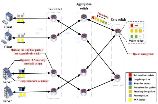
Figure 2.
The architecture of PFDCT.
3.2. Protocol Details
3.2.1. Packet Types
To meet the actual needs of diversified packet identification, PFDCT uses the Differentiated Services Code Point (DSCP) priority specified in the RFC2747 [1] standard in the packet header and uses the first 6 bits of the 8 bits of the Type of Services (ToS) field to assign priority for specific packets (long-flow packets, short-flow packets, and retransmission packets). At the same time, PFDCT only enables the ECN algorithm for the long flow and sets the ECN field of the short flow header to invalid at the data-sending end. The reason for this is that we realized that traditional ECN marking methods indiscriminately drop packets that exceed the queue threshold but the short-flow packets are usually very sensitive to latency. When coexisting with long-flow packets, it often occupies less bandwidth and cannot compete with long-flow packets, so it is in a very disadvantageous position. When the packets exceeding the queue threshold include short-flow packets, the short-flow packets are also discarded. This operation has great interference with the transmission of short flows, which is considered to be the excessive control of ECN on short-flow packets.
3.2.2. Switch Service Model
The switch in this solution supports ECN tag recognition and uses RED queue management algorithm and priority queue management algorithm to identify the priority area of the packet header.
PFDCT sets two thresholds for the RED algorithm, a high threshold and a low threshold ( and ). When the average queue length exceeds , all arriving packets are marked by ECN. When the average queue length is between and , each arriving packet will be marked by ECN with a certain probability, which varies with the average queue length. By doing so, RED can reduce the proportion of ECN marked packets when the queue length is between and , which can reduce the overreaction of the sender and thus keep the throughput high. Therefore, PFDCT improves the RED algorithm so that the queue length threshold in RED is the same as that used in PFDCT, which is dynamic and can greatly reduce the packet loss rate in the traditional RED algorithm. In addition, PFDCT will no longer perform ECN marking on short flows and provide higher priority for short-flow packets to reduce the transmission delay of short flows.
PFDCT’s queue management algorithm implements a strict priority policy, where packets are dequeued from bands only if higher priority bands are all empty. It is a sorted queue tray that can have any number of bands, each band being handled by any type of queue tray. There is no limit to the capacity of the queue disk, and data packets can only be discarded by the sub-queue disk (there may be a capacity limit). It should be noted that the queue disk needs at least two sub-queue disks. In the scenario of this experiment, PFDCT added two sub-queue disks to the queue disk, both of which are RED queue disks.
3.2.3. Discriminating Priority Assignment
To further provide high-quality transmission for short and long flows, PFDCT maintains different queuing queues for long and short flows on the switch. The forwarding priorities of the two queues are different, and the priority of short flows is higher than that of long flows. PFDCT brings two innovations in the priority-based forwarding mechanism: (1) it treats the retransmitted packets as the most urgently delivered packets, and (2) it further refines the existing short flows and long flow classification criteria, selectively giving higher priority only to packets requiring shorter FCT.
PFDCT regards the maximum cwnd as a rough measure of short flows and considers a maximum cwnd less than 20 as one of the characteristics of small flows. In general, PFDCT’s flow classification method is based on two features of flows, including flow size and maximum congestion window. If the flow size is greater than 1 MB and the maximum congestion window is greater than 20, classify the flow as a long flow. Otherwise, classify this flow as a short flow. In PFDCT, the retransmitted packet is given the highest priority regardless of whether it belongs to the long-flow packet or the short-flow packet. Short-flow packets are given the second highest priority, while long-flow packets are given the lowest priority.
Algorithm 1 describes how PFDCT works on switches. In our scheme, the switch classifies incoming packets by identifying the ECN field in the packet header and retrieving the PIT table, and forwards these packets out according to their corresponding priority, which will help PFDCT achieve differentiated management of data center network traffic. When the data packet arrives at the switch, PFDCT will use the function to determine whether the data packet to be forwarded is a retransmitted data packet, and the return value type of this function is Boolean (lines 1–6). PFDCT will first check whether the sequence number of the data packet already exists in the PIT of the switch. If it already exists, it indicates that the data packet is a retransmission packet, otherwise, the data packet is a fresh packet, then the function returns the retransmission flag value. The function is used to assign forwarding priorities to different types of packets. When the data packet is a retransmission packet, PFDCT will give it the highest priority. Otherwise, PFDCT will check the ECN flag. When the flag bit of the data packet is not activated, it means that the data packet is a short-flow data packet, and PFDCT will give the data packet the second-highest priority; otherwise, the data packet is a long-flow data packet, and PFDCT will give the data packet lowest priority of the three (lines 7–13). Next, the algorithm obtains the priority bands (lines 14–15). The function is used to assign priority bands to packets of different priorities, that is, to maintain different priority forwarding queues in the switch buffer. Then function uses the packet filter to sort the packets and return the ret tag. If the filter fails to filter out a packet of that priority, PFDCT obtains the priority of the packet and puts it into the corresponding priority band (lines 16–22). Otherwise, the value of ret is assigned to the priority band, which means there is a packet filter with a corresponding value of ret, and the packet filter is returned (lines 23–25). If the selected band is out of range, the packet is queued on the queue disk and finally, PFDCT returns the packet filter value (lines 26–27).
| Algorithm 1 PFDCT Switch |
Input: SocketPriorityTag priorityTag Output: prioband
|
3.2.4. Congestion Window Update
In this part, PFDCT uses queue length as auxiliary congestion feedback to mark packets more carefully. At each RTT, PFDCT estimates the current queue length as:
where represents the minimum RTT, represents the current RTT and cwnd represents the current congestion window. Unless otherwise noted, we use the parameter description in Table 1.

Table 1.
Parameters and description.
Next, we will discuss how to queue lengths are used to determine congestion levels. When the sender receives the ACK packet, the sender estimates the queue length according to the RTT and further updates the queue length threshold. Specifically, PFDCT marks arriving packets when the instantaneous queue length is larger than a predefined threshold. After all packets in this congestion window are acknowledged, PFDCT can obtain the sum of marked packets. The network congestion degree can be characterized by calculating the proportion of marked packets in the entire window. Larger means more severe congestion. Then the reduction factor in PFDCT is updated once for each data window (approximately one RTT) as follows, and the g value is the same as used in DCTCP:
After that, PFDCT will update the congestion window based on the congestion level. The traditional TCP adopts the AIMD algorithm to update its cwnd. When congestion occurs, AIMD cuts cwnd by half which is appropriate when transferring data over the Internet. However, due to the extremely low latency and shorter flow characteristics of data center networks, the Multiplicative Decrease (MD) algorithm is too aggressive and does not perform well in data center networks. PFDCT improves TCP in data center networks by moderately reducing cwnd according to the congestion degree.
According to Equation (3), when no marked packet ( = 0) is received, the congestion window increases by 1. If at this time, which means that packets are marked and the network is in the congestion state, PFDCT will reduce the congestion window gently according to the congestion level in each round.
3.2.5. Dynamic ECN Marking Threshold Setting
Our suggestion is to decide whether to reduce the sending rate to avoid congestion according to the current congestion level. As the pioneer of the data center network transmission protocol, DCTCP uses the ECN marking scheme to improve TCP and make it suitable for the data center network. However, the fixed ECN threshold is difficult to meet the strict requirements of data centers for traffic transmission due to the complexity of the modern data center network traffic, and the diversity, and dynamics of the network environment. Therefore, the PFDCT protocol uses a dynamic ECN marking threshold algorithm to generate an adaptive marking threshold based on traffic awareness. The algorithm sets an appropriate value for each long flow according to the characteristics of the flow. It should be noted that PFDCT does not use the same marking algorithm for short flows, in other words, short-flow packets will not be constrained. This implementation is supported by the switch model in this scenario, which is detailed in the switch model section.
If the queue length exceeds a given threshold, PFDCT will mark the packet. PFDCT reduces packet loss and retransmission timeouts by keeping the switch’s queue length around a threshold. Specifically, setting a marking threshold for ECN too high can lead to packet accumulation and unnecessary queuing, which introduces high end-to-end transport latency. Conversely, if the threshold is too small, the bottleneck link will not be fully utilized, resulting in reduced throughput. In order to balance queuing delay and link utilization, PFDCT sets an adjustment range for , the upper boundary is called , and the lower boundary is called . Preset an ideal target threshold for the queue length to maintain an appropriate end-to-end queue length. In short, the threshold will be updated as Equation (5). The in Equation (4) indicates the average queue length, that is:
where h is a weight parameter and satisfies 0 < h < 1.
Next, we analyze the minimum and maximum queue oscillation to obtain an optimal threshold and achieve low latency without sacrificing the throughput. PFDCT denotes the link capacity (packets/second) as C, the round trip time as RTT, and the number of flows as N. We assume that the N window sizes are synchronized and follow the identical sawteeth, then the queue size at time t is given by:
We assume that the queue length of the switch at this point is exactly equal to the threshold sum of each flow, then we can obtain:
At the next moment, since no congestion is detected on the link, the window of each flow will increase by 1 according to the window modulation algorithm, then:
Now the queue length exceeds a preset threshold, all the senders will observe a positive queuing delay, and they respond by decreasing the window size using the multiplicative factor:
As mentioned above, the change of the switch queue length always follows the sawtooth model, so it is not difficult to deduce that the queue length at is equal to , namely:
It can be seen from DCTCP that , and if Equation (7) is substituted into Equation (6), we can calculate the relation between W(t) and and N as:
Further, PFDCT converts into an algebraic expression completely related to thresholds and N:
where , it means that the minimum queue length should be greater than 0 packet to ensure higher link utilization. Thus, we can obtain:
This results in:
For convenience, the inequality 14 is denoted by , and it is not difficult to see that is the inverse function of the number of concurrent flows N. In other words, if the threshold satisfies the inequality when N = 1, will obtain smaller as the number of concurrent flows increases and the threshold will satisfy the inequality. Finally, we can obtain the ideal marking threshold as:
After obtaining the ideal threshold , PFDCT needs to further determine the upper limit and lower limit of the marking threshold. Considering the burstiness and concurrency of data center traffic, the total threshold of concurrent traffic must be smaller than the buffer capacity M of the bottleneck switch, i.e., , . After comprehensive consideration, used in this experiment is 0, and is M/N, which will be adjusted according to the bandwidth and delay.
Algorithm 2 describes how PFDCT works on the sender side. The main tasks include simple processing of packet headers to distinguish between long and short flows, obtaining link status in real time, setting dynamic thresholds for long flow queue markers, and modulating congestion windows. Firstly, PFDCT uses the function to read the retransmission flag, flow size, and congestion window size of packets to distinguish between long-flow packets, short-flow packets, and retransmission packets. The division of long-flow packets and short-flow packets should first confirm that they all belong to non-retransmission packets. The sender enables ECN when the function determines that the packet belongs to the long flow, otherwise the sender sets the ECN flag to inactive (lines 1–7). Next, PFDCT calls the function to obtain the queue length in the bottleneck switch using the method demonstrated in Equation (1) (lines 10–12), and the function to obtain the ideal queue marking threshold under the current experimental parameters using Equation (15). PFDCT sets the right-hand expression of inequality 14 to . It can be seen that is an inverse function with respect to the number of concurrent flows N. In other words, if the marking threshold can satisfy the inequality when N = 1, then as N keeps increasing, the value of becomes smaller instead, and the threshold must also satisfy the inequality, at which point the value of as a function of at N = 1 can be set to the ideal marking threshold (lines 7–9). When all messages in the window have been received, PFDCT calls the function to update the marker threshold for the ECN. If the average queue length at this point is greater than the ideal threshold, PFDCT will raise the marker threshold, otherwise, it will lower the marker threshold (lines 13–24). Finally, the function will calculate a new congestion window value based on the proportion of packets that are marked. That is, when the proportion of marked packets is 0, the congestion window is increased by 1. When the proportion of marked packets is greater than 0 ( > 0), the sender reduces the congestion window according to the value of the congestion factor (lines 25–32).
To sum up, PFDCT strictly classifies data center traffic and provides different forwarding priorities to meet its transmission requirements. In particular, PFDCT combines ECN feedback and RTT feedback, which are most common in data center networks, to capture link information more accurately. In order to change the poor adaptability of the fixed marking threshold in DCTCP, PFDCT utilizes the queue length information to make the marking threshold change in real-time according to the network congestion state, further improving the network throughput. The next chapter provides a performance comparison of the two protocols.
| Algorithm 2 PFDCT Sender |
Input: Flowsize Urgencydegree Output: The updated threshold
|
4. Impact of the Threshold of PFDCT
To illustrate the positive impact of the dynamic threshold-based packet marking algorithm on PFDCT, we test the performance of PFDCT in terms of latency, FCT, and packet loss rate when using dynamic thresholds and fixed thresholds, respectively, and compare them. In addition, we refer to PFDCT with a fixed threshold as PFDCT-ST in this section for convenience.
The network topology used for simulation in this section is a three-level fat tree topology with 250 servers, 25 core switches, and 10 pods, with 5 aggregation switches and 5 Top of Rack (ToR) switches in each pod. This topology is typical in data center networks, also used in the evaluation of recently proposed protocols [4,16,20,34]. Each ToR switch is connected to up to 20 servers with a 1 GB link. All switches have a buffer size of 100 packets, and the packet size is 1.5 KB, the link delay is 10 µs.
In the many-to-one traffic context, clients receive data from servers located in the same rack or randomly selected servers. In each run, we simulated 2000 transfer sessions (or I/O requests), each of size 1 MB and 4 MB. Each I/O request is randomly assigned to a host in the network as a client. The placement of each data block is based on the Hadoop Distributed File System (HDFS) default strategy, more specifically, we assume that the client itself is not the server, and the data blocks are placed on other random nodes on the same rack. If no data block is stored in the same rack, the client will read a data block from a server located in the same rack or from a server chosen at random.
Flow Completion Time. Figure 3 shows the FCT performance comparison curves of PFDCT and PFDCT-ST. When the time is less than 0.02 ms, PFDCT behaves similarly to PFDCT-ST, and when the time is greater than 0.04 ms, the FCT of PFDCT-ST gradually increases and is higher than that of PFDCT. It is not difficult to see that PFDCT has stronger adaptability and can keep the FCT of the data flow stable when the network environment changes, while PFDCT-ST is greatly affected by the network environment changes and the network changes and the FCT of the data flow presents an increasing trend.
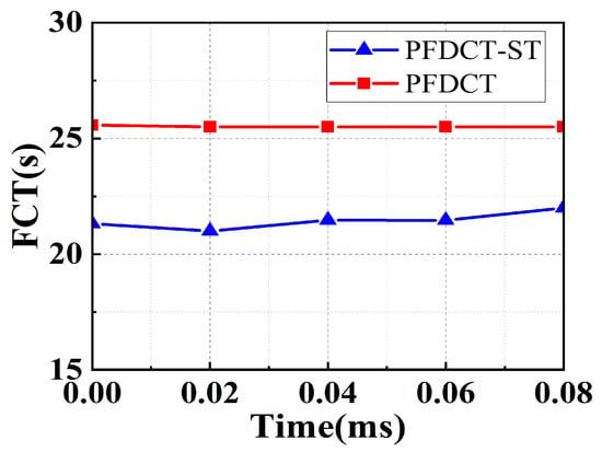
Figure 3.
FCT comparison between PFDCT and PFDCT-ST.
Loss rate. It can be seen from Figure 4 that in the case of stable data transmission, the packet loss rate of the network using the PFDCT protocol remains at 0, and the most serious packet loss rate is about 0.002% which can be ignored. Compared with PFDCT, PFDCT-ST loses more packets but it is gratifying that the maximum packet loss rate of PFDCT-ST can still be kept below 0.01%, which may benefit from the priority scheduling strategy.
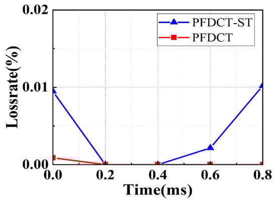
Figure 4.
Loss rate comparison between PFDCT and PFDCT-ST.
Delay. It is clear from Figure 5 that the average delay of PFDCT is 50% lower than PFDCT-ST. Moreover, as the data volume increases, PFDCT can still maintain almost zero end-to-end delay, while PFDCT-ST shows an increasing trend. This indicates that the marking algorithm using a fixed threshold can hardly cope with severe data congestion when the data volume increases, using a dynamic threshold is more suitable for a data center network with heavy load and multiple senders, and can effectively avoid TCP incast.
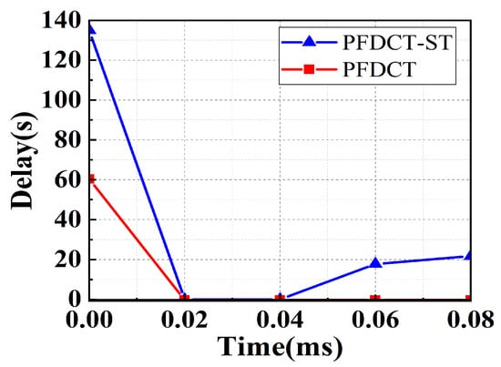
Figure 5.
End-to-end delay comparison between PFDCT and PFDCT-ST.
5. Evaluation
We have extensively evaluated PFDCT’s performance through large scale, packet-level simulations and compared it to the state of the art. To do so, we tested PFDCT for throughput, FCT, packet loss, and fairness, analyzing its performance differences with DCTCP, ICTCP, and L2DCT.
5.1. Simulation Setup
We conduct simulation experiments under two different topologies, including simple-scale topology and large-scale topology. We set the minimum RTO of TCP to 200 µs and the average size of packets to 1.5 KB. The default link bandwidth is 1 GB, and the default link delay is 10 µs. Each switch port in the simulation has a shallow buffer that can only hold 100 packets (approximately 100 × 1.5 KB = 150 KB). In the experiment, we set the g value as 1/16, the maximum marking threshold of the switch queue is 60, and the minimum marking threshold is 20 packets.
DCTCP [23]: DCTCP uses a very simple AQM technique on the switch. When the number of packets in the queue is greater than the marking threshold K, packets arriving after that are marked with CE code point. For packets marked with the CE code point, the receiver sets the ECN-echo flag of the corresponding ACK and estimates the proportion of marked packets at the sender. Finally, DCTCP will adjust the congestion window size according to the degree of congestion.
ICTCP [12]: ICTCP calculates the available bandwidth and throughput of the receiving end every two . ICTCP is deployed at the receiving end of the data center, and adjusts the size of the sliding window by detecting bandwidth utilization to fully utilize link resources. It divides the total bandwidth into two parts, the first part is used to receive all traffic and predict the bandwidth utilization, and this value is used to adjust the sliding window of the remaining part of the bandwidth in turn.
L2DCT [35]: L2DCT also uses ECN as congestion feedback, and uses and traffic weight to adjust the congestion window. is the same as used in DCTCP, while weights are assigned to the flow by estimating data sent so far. When both long and short flows exist, the short flows will obtain a higher bandwidth share, and when only long flows exist, L2DCT will penalize them. In case of severe congestion, all traffic shares fall back off entirely.
5.2. Simple-Scale Experiments
In this experiment, we measured the impact of the PFDCT protocol on the link throughput and FCT under different loads. Many previous works have shown that the number of concurrent flows is an important parameter affecting the performance of the scheme, so we also compare the performance of various mechanisms when there are different numbers of concurrent flows to verify the practicality of the scheme. In the topology scenario shown in Figure 1, we set up multiple concurrent senders to send data to the same receiver at the same time and all hosts are under the same switch, which is a typical TCP incast scene.
Throughput. In this part we measure the application throughput for PFDCT in a distributed storage setup which involves many-to-one communication. In each run, we simulate different numbers of transport sessions with sizes of 1.5 KB each. Furthermore, we generate different link loads and evaluate how PFDCT works compared to other schemes. We measure the overall throughput from the time the client initiates the transmission until the last server receives the whole data. The results for various loads and concurrent flows are shown in Figure 6. From Figure 6a, we can see that PFDCT performs load balancing between short-flow packets and long-flow packets, and its throughput has always maintained an advantage of around 5 MB above DCTCP even with the increasing number of concurrent flows. As the number of concurrent flows continues to increase, the change in link throughput brought by PFDCT is very similar to ICTCP and L2DCT. We believe that the reason is PFDCT gives short flows more opportunities to transmit and restricts the transmission of long flows that are more capable of providing throughput accordingly.
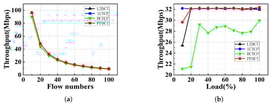
Figure 6.
Throughput comparison of multiple schemes in simple-scale topology. (a) Throughput comparison with varying flow numbers. (b) Throughput comparison with varying load.
Keeping the above configuration unchanged and controlling the number of concurrent flows to 30, we tested the performance of PFDCT and other schemes under different loads. As we can see in Figure 6b, the performance of PFDCT is still significantly higher than that of DCTCP, and the throughput of PFDCT is about 30% higher than that of DCTCP when the load is not heavy. For 100% link load, PFDCT shows the best performance that we measured an average throughput of 32.35 MB for PFDCT, a 0.41 MB improvement over the highest value in the comparison schemes.
Flow Completion Time. Next, we tested FCT for various protocols to see how the performance of PFDCT would improve compared to previous transport protocols. We showed the average FCT for multiple protocols with different numbers of concurrent flows in Figure 7a and the specific values can be seen in Table 2. PFDCT performs the best in scenarios where the number of flows is high (greater than 20) due to priority delivery for short flows and the supported multiple queue management mechanisms.
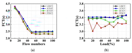
Figure 7.
The average FCT comparison of multiple schemes in simple-scale topology. (a) The average FCT comparison with varying flow numbers sending 1500 KB flows. (b) The average FCT comparison with varying load sending 1500KB flows.
Table 2.
The average FCT with varying numbers of senders sending 15 KB flows in simple-scale topology.
We fixed the average flow data size at 1.5 MB and the number of concurrent flows at 30 and kept increasing the link load to test the variation of FCT for PFDCT under different loads. Figure 7b shows the statistics of the average FCT of PFDCT, L2DCT, DCTCP, and ICTCP. At high loads, PFDCT reduces the average flow transmission time by more than 250 ms, and the multi-queue management mechanism makes it unnecessary for PFDCT to trim packets belonging to short flows. Under the same conditions, PFDCT reduces FCT by about 15% relative to DCTCP which confirms the network can provide shorter FCT by using a dynamic ECN marking threshold mechanism. Figure 8 further depicts the distribution law of the average FCT when every protocol acts on the network with different loads.
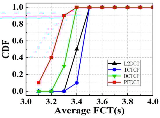
Figure 8.
The average FCT with varying link load.
5.3. Large-Scale Experiments
As shown in Figure 9, we used a FatTree topology with 160 servers, which has four topologies A, B, C, and D, and each pod has eight core switches and two aggregation switches. The buffer size of the ToR switch and aggregation switch shown in the figure is 100 data packets, and the buffer size of the core switch is 250 data packets. The link bandwidth between the aggregation switch and the core switch is 10 GB by default, and the link bandwidth between other devices is 1 GB by default. Meanwhile, we set the default values of link delay and RTT to 50 µs and 300 µs, respectively, and run each simulation multiple times to report the average values or the aggregate values.
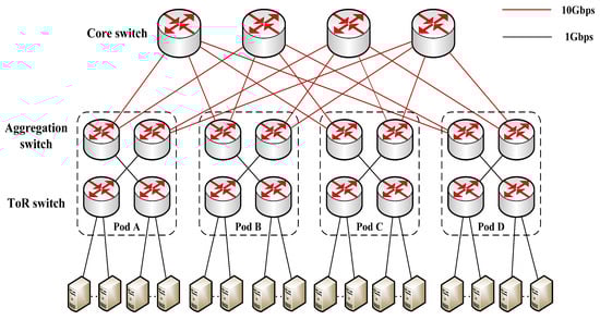
Figure 9.
The topology for large-scale experiments.
In each run, we simulate 60 transfer sessions of size 100 KB and 2 transfer sessions of size 2 MB from Pod A to Pod D (traffic one), 70 transfer sessions of size 200 KB, and 5 transfer sessions of size 2 MB from Pod B to Pod D (traffic two), and 90 transfer sessions of size 300 KB in Pod C (traffic three). By doing so, the receiver can receive traffic from the sender located in the same pod (traffic three) and different pods (traffic one and two), respectively, which is a typical data center traffic transfer mode.
Throughput. We plotted the average throughput of traffic one of four mechanisms at varying times in Figure 10 and the specific values can be seen in Table 3. PFDCT exhibits similar performance to DCTCP because the sender increases the congestion window linearly at begin continuously. It is worth noting that, unlike other protocols, the PFDCT protocol allows the throughput of the link to continue to climb over time. This is because the short flow reaches the sender in time, freeing up a large amount of transmission bandwidth on the link and providing more transmission space for the long flow.
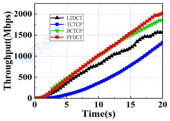
Figure 10.
Throughput comparison of multiple schemes in large-scale topology.
Table 3.
Throughput comparison of multiple schemes in large-scale topology.
Flow Completion Time. As we can see from Figure 11a, the performance of PFDCT is similar to other schemes since the available bandwidth of the link is sufficient at the beginning. As the data starts to obtain more and more and the network environment becomes more complex, PFDCT can still maintain a low FCT proving that PFDCT can provide more stable transmission performance for the link compared to other protocols. Figure 11b further depicts the distribution law of the average FCT when every protocol acts on the network.
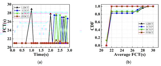
Figure 11.
The average FCT comparison of multiple schemes in large-scale topology. (a) The average FCT comparison with varying time. (b) The CDF of average FCT.
Loss rate. Simulation data for loss rate in large-scale experiments are analyzed and compared in this part. We can see from Figure 12 that PFDCT achieves the same zero packet loss rate as DCTCP and ICTCP, except that the packet loss rate of L2DCT exhibits oscillation below 0.05%.
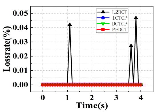
Figure 12.
Loss rate comparison of multiple schemes in large-scale topology.
Fairness. We conducted fairness index tests on PFDCT and other protocols to show that PFDCT can achieve a fair share of bandwidth among various traffic. As can be seen from Figure 13, the fairness index of PFDCT was always on the rise before 8 s, after then the fairness index remained at about 0.55, which confirms that PFDCT can achieve more reasonable bandwidth sharing between short and long flows by giving short flows a higher priority.
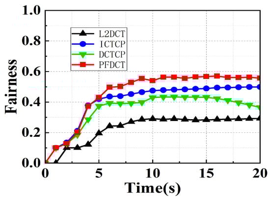
Figure 13.
Jain’s fairness index in large-scale topology.
6. Conclusions
In this paper, we proposed PFDCT, a transport layer protocol that addresses TCP incast problem for data centers. It is the first transport protocol that committed to congestion control for so many types of traffic in a data center network while performing at least as well as the state of the art concerning goodput and FCT for long and short flows. PFDCT achieves this remarkable combination by integrating AQM and delay-based congestion feedback with joint flow control between sender and intermediate, packet classification, and in-network priority scheduling. This paper also discussed the impact of the marking algorithm with dynamic thresholds on the performance of PFDCT at last, and the results of the experiments show that the addition of the marking algorithm will further improve the performance of PFDCT in terms of packet loss rate, latency, and FCT. The delay-based link state feedback method, congestion window modulation algorithm, and dynamic threshold marking method are deployed on the sending side. The priority-based multi-queue management method only relies on the intermediate device switch to identify packet header specific fields to assist in implementation. PFDCT has good generality and negligible modifications to the switch side of modern data center networks.
Author Contributions
Conceptualization, Z.L., H.W. and X.Y.; formal analysis, Z.L., H.W. and X.Y.; software, H.W., X.Z., J.W. and Y.Z.; writing—original draft preparation, H.W. and Z.L.; writing—review and editing, H.W. and Z.L.; funding acquisition, Z.L., P.L. and K.L. All authors have read and agreed to the published version of the manuscript.
Funding
This document is the results of the research project funded by the National Key R & D Program of China under Grant 2022YFB2901100, the Key R & D projects of Hebei Province under Grant 20314301D and the Peng Cheng Laboratory Project under Grant PCL2021A02.
Data Availability Statement
Due to the nature of this research, participants of this study did not agree for their data to be shared publicly, so supporting data is not available.
Conflicts of Interest
The authors declare no conflict of interest.
References
- Alipio, M.; Tiglao, N.M.; Bokhari, F.; Khalid, S. TCP incast solutions in data center networks: A classification and survey. J. Netw. Comput. Appl. 2019, 146, 102421. [Google Scholar] [CrossRef]
- Alasmar, M.; Parisis, G.; Crowcroft, J. SCDP: Systematic Rateless Coding for Efficient Data Transport in Data Centres (Complete Version). arXiv 2019, arXiv:1909.08928. [Google Scholar]
- Devkota, P.; Reddy, A.N. Performance of quantized congestion notification in TCP incast scenarios of data centers. In Proceedings of the 2010 IEEE International Symposium on Modeling, Analysis and Simulation of Computer and Telecommunication Systems, Miami Beach, FL, USA, 17–19 August 2010; IEEE: Piscataway, NJ, USA, 2010; pp. 235–243. [Google Scholar] [CrossRef]
- Mittal, R.; Lam, V.T.; Dukkipati, N.; Blem, E.; Wassel, H.; Ghobadi, M.; Vahdat, A.; Wang, Y.; Wetherall, D.; Zats, D. TIMELY: RTT-based congestion control for the datacenter. ACM SIGCOMM Comput. Commun. Rev. 2015, 45, 537–550. [Google Scholar] [CrossRef]
- Rezaei, H.; Chaudhry, M.U.; Almasi, H.; Vamanan, B. Icon: Incast congestion control using packet pacing in datacenter networks. In Proceedings of the 2019 11th International Conference on Communication Systems & Networks (COMSNETS), Bengaluru, India, 7–11 January 2019; IEEE: Piscataway, NJ, USA, 2019; pp. 125–132. [Google Scholar] [CrossRef]
- Le, L.; Aikat, J.; Jeffay, K.; Smith, F.D. Differential congestion notification: Taming the elephants. In Proceedings of the 12th IEEE International Conference on Network Protocols, ICNP 2004, Washington, DC, USA, 5–8 October 2004; IEEE: Piscataway, NJ, USA, 2004; pp. 118–128. [Google Scholar]
- Abdelmoniem, A.M.; Bensaou, B. Curbing timeouts for TCP-incast in data centers via a cross-layer faster recovery mechanism. In Proceedings of the IEEE INFOCOM 2018—IEEE Conference on Computer Communications, Honolulu, HI, USA, 16–19 April 2018; IEEE: Piscataway, NJ, USA, 2018; pp. 675–683. [Google Scholar] [CrossRef]
- Wu, H.; Farha, F.; Hong, T.; Xu, Y.; Zhang, T. CWND: A Coarse, But Simple, Efficient Metric to Reduce Short Flow Completion Time in Data Centers. IEEE Access 2019, 7, 172496–172504. [Google Scholar] [CrossRef]
- Bai, W.; Chen, K.; Wu, H.; Lan, W.; Zhao, Y. PAC: Taming TCP incast congestion using proactive ACK control. In Proceedings of the 2014 IEEE 22nd International Conference on Network Protocols, Raleigh, NC, USA, 21–24 October 2014; IEEE: Piscataway, NJ, USA, 2014; pp. 385–396. [Google Scholar] [CrossRef]
- Huang, J.; He, T.; Huang, Y.; Wang, J. ARS: Cross-layer adaptive request scheduling to mitigate TCP incast in data center networks. In Proceedings of the IEEE INFOCOM 2016—The 35th Annual IEEE International Conference on Computer Communications, San Francisco, CA, USA, 10–14 April 2016; IEEE: Piscataway, NJ, USA, 2016; pp. 1–9. [Google Scholar] [CrossRef]
- Lee, C.; Park, C.; Jang, K.; Moon, S.; Han, D. Accurate latency-based congestion feedback for datacenters. In Proceedings of the 2015 USENIX Annual Technical Conference (USENIX ATC 15), Santa Clara, CA, USA, 8–10 July 2015; pp. 403–415. [Google Scholar]
- Wu, H.; Feng, Z.; Guo, C.; Zhang, Y. ICTCP: Incast congestion control for TCP in data-center networks. IEEE/ACM Trans. Netw. 2012, 21, 345–358. [Google Scholar] [CrossRef]
- Ramakrishnan, K.; Floyd, S.; Black, D. The Addition of Explicit Congestion Notification (ECN) to IP; Technical Report; IETF: Fremont, CA, USA, 2001. [Google Scholar]
- Pan, R.; Prabhakar, B.; Laxmikantha, A. QCN: Quantized congestion notification. In Proceedings of the IEEE802, Geneva, Switzerland, 29 May 2007; Volume 1, pp. 52–83. [Google Scholar]
- Luo, J.; Yang, X.; Zhang, C. CCMA: A Dynamical Concurrent-Connection Management Agent to Mitigate TCP Incast in Datacenters. IEEE Access 2019, 7, 63303–63320. [Google Scholar] [CrossRef]
- Suryavanshi, M.; Kumar, A.; Yadav, J. An application layer technique to overcome TCP incast in data center network using delayed server response. Int. J. Inf. Technol. 2021, 13, 703–711. [Google Scholar] [CrossRef]
- Wang, H.; Shen, H. Proactive incast congestion control in a datacenter serving web applications. In Proceedings of the IEEE INFOCOM 2018—IEEE Conference on Computer Communications, Honolulu, HI, USA, 16–19 April 2018; IEEE: Piscataway, NJ, USA, 2018; pp. 19–27. [Google Scholar]
- Zou, S.; Huang, J.; Wang, J.; He, T. Flow-aware adaptive pacing to mitigate TCP incast in data center networks. IEEE/ACM Trans. Netw. 2020, 29, 134–147. [Google Scholar] [CrossRef]
- Kumar, G.; Dukkipati, N.; Jang, K.; Wassel, H.M.; Wu, X.; Montazeri, B.; Wang, Y.; Springborn, K.; Alfeld, C.; Ryan, M.; et al. Swift: Delay is simple and effective for congestion control in the datacenter. In Proceedings of the Annual Conference of the ACM Special Interest Group on Data Communication on the Applications, Technologies, Architectures, and Protocols for Computer Communication, Virtual Event, 10–14 August 2020; pp. 514–528. [Google Scholar]
- Huang, J.; Huang, Y.; Wang, J.; He, T. Adjusting packet size to mitigate TCP incast in data center networks with COTS switches. IEEE Trans. Cloud Comput. 2018, 8, 749–763. [Google Scholar] [CrossRef]
- Cheng, P.; Ren, F.; Shu, R.; Lin, C. Catch the whole lot in an action: Rapid precise packet loss notification in data center. In Proceedings of the 11th USENIX Symposium on Networked Systems Design and Implementation (NSDI 14), Seattle, WA, USA, 2–4 April 2014; pp. 17–28. [Google Scholar]
- Floyd, S.; Jacobson, V. Random early detection gateways for congestion avoidance. IEEE/ACM Trans. Netw. 1993, 1, 397–413. [Google Scholar] [CrossRef]
- Alizadeh, M.; Greenberg, A.; Maltz, D.A.; Padhye, J.; Patel, P.; Prabhakar, B.; Sengupta, S.; Sridharan, M. Data center tcp (dctcp). In Proceedings of the ACM SIGCOMM 2010 Conference, New Delhi, India, 30 August–3 September 2010; pp. 63–74. [Google Scholar] [CrossRef]
- Bai, W.; Chen, L.; Chen, K.; Wu, H. Enabling ECN in multi-service multi-queue data centers. In Proceedings of the 13th USENIX Symposium on Networked Systems Design and Implementation (NSDI 16), Santa Clara, CA, USA, 16–18 March 2016; pp. 537–549. [Google Scholar]
- Shan, D.; Ren, F. Improving ECN marking scheme with micro-burst traffic in data center networks. In Proceedings of the IEEE INFOCOM 2017—IEEE Conference on Computer Communications, Atlanta, GA, USA, 1–4 May 2017; IEEE: Piscataway, NJ, USA, 2017; pp. 1–9. [Google Scholar] [CrossRef]
- Wang, S.; Zhang, J.; Huang, T.; Pan, T.; Liu, J.; Liu, Y. A-ECN minimizing queue length for datacenter networks. IEEE Access 2020, 8, 49100–49111. [Google Scholar] [CrossRef]
- Vasudevan, V.; Phanishayee, A.; Shah, H.; Krevat, E.; Andersen, D.G.; Ganger, G.R.; Gibson, G.A.; Mueller, B. Safe and effective fine-grained TCP retransmissions for datacenter communication. ACM SIGCOMM Comput. Commun. Rev. 2009, 39, 303–314. [Google Scholar] [CrossRef]
- Xu, Y.; Shukla, S.; Guo, Z.; Liu, S.; Tam, A.S.W.; Xi, K.; Chao, H.J. RAPID: Avoiding TCP incast throughput collapse in public clouds with intelligent packet discarding. IEEE J. Sel. Areas Commun. 2019, 37, 1911–1923. [Google Scholar] [CrossRef]
- Abdelmoniem, A.M.; Bensaou, B. T-RACKs: A faster recovery mechanism for TCP in data center networks. IEEE/ACM Trans. Netw. 2021, 29, 1074–1087. [Google Scholar] [CrossRef]
- Sreekumari, P.; Jung, J.I.; Lee, M. A simple and efficient approach for reducing TCP timeouts due to lack of duplicate acknowledgments in data center networks. Clust. Comput. 2016, 19, 633–645. [Google Scholar] [CrossRef]
- Zhang, J.; Ren, F.; Tang, L.; Lin, C. Modeling and solving TCP incast problem in data center networks. IEEE Trans. Parallel Distrib. Syst. 2014, 26, 478–491. [Google Scholar] [CrossRef]
- Zhuang, J.; Jiang, X.; Jin, G.; Zhu, J.; Chen, H. PTCP: A priority-driven congestion control algorithm to tame TCP incast in data centers. IEEE Access 2019, 7, 38880–38889. [Google Scholar] [CrossRef]
- Alizadeh, M.; Greenberg, A.; Maltz, D.; Padhye, J.; Patel, P.; Prabhakar, B.; Sengupta, S.; Sridharan, M. DCTCP: Efficient Packet Transport for the Commoditized Data Center; ACM SIGCOMM: Amsterdam, The Netherlands, 1973; pp. 1–15. [Google Scholar]
- Xu, L.; Xu, K.; Jiang, Y.; Ren, F.; Wang, H. Throughput optimization of TCP incast congestion control in large-scale datacenter networks. Comput. Netw. 2017, 124, 46–60. [Google Scholar] [CrossRef]
- Munir, A.; Qazi, I.A.; Uzmi, Z.A.; Mushtaq, A.; Ismail, S.N.; Iqbal, M.S.; Khan, B. Minimizing flow completion times in data centers. In Proceedings of the 2013 Proceedings IEEE INFOCOM, Turin, Italy, 14–19 April 2013; IEEE: Piscataway, NJ, USA, 2013; pp. 2157–2165. [Google Scholar] [CrossRef]
Disclaimer/Publisher’s Note: The statements, opinions and data contained in all publications are solely those of the individual author(s) and contributor(s) and not of MDPI and/or the editor(s). MDPI and/or the editor(s) disclaim responsibility for any injury to people or property resulting from any ideas, methods, instructions or products referred to in the content. |
© 2023 by the authors. Licensee MDPI, Basel, Switzerland. This article is an open access article distributed under the terms and conditions of the Creative Commons Attribution (CC BY) license (https://creativecommons.org/licenses/by/4.0/).