
Analysis of Electrostatic Discharge Interference Effects on Small Unmanned Vehicle Handling Systems

1
National Key Laboratory on Electromagnetic Environment Effects, Shijiazhuang Campus, Army Engineering University of PLA, Shijiazhuang 050003, China
2
School of Information Science and Engineering, Hebei University of Science and Technology, Shijiazhuang 050018, China
3
Hebei Technology Innovation Centre of Intelligent IoT, Shijiazhuang 050018, China
*
Authors to whom correspondence should be addressed.
Electronics 2023, 12(7), 1640; https://doi.org/10.3390/electronics12071640
Submission received: 19 February 2023
/
Revised: 28 March 2023
/
Accepted: 28 March 2023
/
Published: 30 March 2023
(This article belongs to the Special Issue Advancements in Electromagnetic Compatibility (EMC) Techniques for Electronic Systems)
Abstract
:Electrostatic discharge is a common phenomenon in daily life, and the electromagnetic pulse radiation generated during discharge can cause great harm to power, communication, sensing, and other equipment, resulting in systems not working properly. To verify the safety and reliability of unmanned vehicle handling systems in complex electromagnetic environments, the interference effect of electrostatic discharge, a common source of electromagnetic interference in life, on unmanned vehicle systems was studied. According to the electrostatic discharge interference mechanism, typical electrostatic discharge mode, and discharge model, an unmanned vehicle handling system was tested for electrostatic discharge according to the ISO10605-2008 standard. Based on the measured data, the effect of electrostatic discharge on the safety and functionality of the unmanned vehicle handling system and its sensors was analyzed, and threshold values for the failure of the unmanned vehicle handling system under different discharge methods, discharge models, and discharge polarity were obtained. When the electrostatic discharge voltage amplitude is only 2 kV, the vehicle’s LiDAR data sensor cannot work normally due to the echo reception circuit, and the failure rate of LiDAR continues to increase with increasing discharge voltage. When the discharge voltage is only 4 kV, the millimeter-wave radar is disconnected from the vehicle module due to the electrostatic discharge interference of the transmission cable, and when the discharge voltage is 12 kV, the unmanned vehicle is unable to provide stable and accurate environmental information to avoid collisions. This study provides a reference for the design of electromagnetic protection of unmanned equipment and will have a guiding role in enhancing the construction of reliable, safe, and intelligent equipment in complex electromagnetic environments.
1. Introduction
With the rapid development of artificial intelligence technology, unmanned systems are gradually replacing humans to perform some activities. From small welcoming robots, logistical vehicle handling, and floor-sweeping robots to large driverless cars and unmanned military vehicles, unmanned systems have been used on a large scale [1,2,3,4]. To improve the safety of unmanned systems, perception modules are often needed to replace the driver’s eyes, which usually consist of LiDAR sensors, millimeter-wave radar sensors, camera sensors, and inertial sensors. Although the addition of sensors can improve the safety of road driving, it also increases the coupling pathways of electromagnetic interference. The existing literature mainly focuses on specific cases of electromagnetic interference encountered during the operation of unmanned vehicle handling systems, and proposes simple hardware design improvements [5]. Although electromagnetic interference problems are relatively easy to discover during product usage, the protective measures available are minimal and the protection costs are high. The relationship between the product development phase and electromagnetic interference protection cost is shown in Figure 1. The earlier the problem is discovered, the more likely it is to reduce the cost, and more feasible solutions can be proposed to address electromagnetic interference problems. “China’s current artificial intelligence systems and unmanned equipment in the design, development, and production without considering the adaptability of the harsh electromagnetic environment, especially the problem of electromagnetic attacks by non-cooperative parties, and pointed out that electromagnetic protection bionic technology would provide the unmanned system electromagnetic protection design with new ideas” [6], said academician Shanghe Liu, an expert in electromagnetic fields. In order to ensure that an unmanned vehicle handling system can still maintain stable and safe operation in complex electromagnetic environments, common types of electromagnetic interference in life and the characteristics of interference need to be studied to provide sufficient protection. However, there are currently no comprehensive electromagnetic interference tests for unmanned vehicle handling systems reported in the literature.
With the rapid development of unmanned vehicle systems in industry and service industries, people often have contact with unmanned vehicle handling, increasing the risk of electromagnetic interference. This paper chooses the common electromagnetic interference source electrostatic discharge (ESD) to conduct electromagnetic interference tests on a certain type of unmanned vehicle, and combines the current situation of electromagnetic compatibility standards for certification and testing of traditional vehicles at home and abroad. Based on ISO 10605, “Road vehicles—Test methods for electrical disturbances from electrostatic discharge” [7], the performance of an intelligent unmanned vehicle handling system under static electricity discharge interference was evaluated. Through analyzing and summarizing the test data obtained, the parts of the unmanned vehicle system that are sensitive to static electricity discharge interference were identified as the laser radar sensor and transmission cables. When the sensor cannot continuously transmit correct information on the surrounding environment, the vehicle module cannot achieve obstacle avoidance, leading to the occurrence of collisions. This paper plays an important guiding role in improving the ESD electromagnetic pulse protection capability of unmanned vehicle handling systems.
2. Unmanned Vehicle Handling Systems
Unmanned vehicle handling is an important application of artificial intelligence technology and a new technology that various countries are competing to develop. An unmanned vehicle handling system is an integrated system that combines functions of environment perception, navigation and positioning, and planning and decision-making [8,9,10].
In this paper, a commonly used commercial unmanned vehicle handling system chassis was selected (XTARK INNOVATION-ATOM), which is widely used in the logistics of distribution, meal delivery services, commercial guidance services, and so on. The overall architecture (Figure 2) includes a software system and hardware system. The software system acts as the brain of the unmanned vehicle handling, which is responsible for receiving data uploaded by sensors, performing environmental perception and positioning, and issuing commands to achieve the navigation function. The driver layer serves as a connection between the operating system layer and the hardware layer, responsible for data transmission and communication, including various sensor drivers and motor drivers. The hardware system mainly includes the perception module, processor module, and power supply module. The perception module senses the surrounding environment of the vehicle through three types of sensors: LiDAR, millimeter-wave radar, and camera. The IMU is responsible for measuring the three-axis attitude angle and acceleration, while the encoder provides real-time information. The processor module issues commands based on environmental information and self-information, and the power supply module is responsible for the entire system’s power support.
The operational process of the unmanned vehicle handling system is illustrated in Figure 3. (1) The sensing module composed of laser radar, millimeter-wave radar, camera, and other sensors is responsible for real-time sensing of the surrounding environment. (2) The unmanned vehicle handling computer uses the GMapping mapping algorithm to build a high-precision map based on the surrounding environment detected by the sensors of the sensing module, and marks the vehicle’s drivable area, obstacles, and sensor-undetected areas on the map. (3) By using the extended Kalman filter (EKF) algorithm to fuse the IMU data and odometry data, fused odometry data can be obtained. The adaptive Monte Carlo localization (AMCL) algorithm is used to obtain information on the vehicle’s handling. (4) After establishing a high-precision map and determining the vehicle’s position, the system uses the A* (A-Star) algorithm for global path planning according to the high-precision map to find the optimal driving route between the vehicle’s position and the target point. (5) The task of vehicle control is to digest the output trajectory points of the upper local planning module and complete control of the vehicle through corner control (lateral vehicle control) and speed control (longitudinal vehicle control). The handling system uses the world’s largest robot operating system (ROS) open-source software, which has the functions of underlying device control, distributed communication, data packet management, etc. The raw data of the underlying hardware and the work log of the vehicle system can be recorded and viewed, which is convenient for analyzing fault locations and fault types.
As the most essential part of the unmanned vehicle handling system, the development of the sensing module often determines the degree of application of unmanned driving [11]. The unmanned vehicle handling selected in this experiment includes three sensors: LiDAR, millimeter-wave radar, and camera. LiDAR and the camera can accomplish the task of environmental perception alone. The data from the three sensors can be fused to improve map accuracy. With the reduction in cost of LiDAR in recent years and the advantages of high precision and high reliability, the data returned by the LiDAR can be directly used for calculation in path planning without knowing specific obstacle information [12]. Visual sensors are primarily used in unmanned vehicle handling systems to identify tasks such as lane markings, stop lines, traffic signals, traffic signs, pedestrians, and vehicles. Cameras have the advantage of lower cost compared to other types of sensors. The millimeter-wave radar is mainly used for emergency obstacle avoidance and is installed on the front and sides of the vehicle body. It has the advantages of fast detection, high precision, and less susceptibility to weather interference. However, the low resolution of the millimeter-wave radar cannot meet the needs of navigation, and it is usually used in fusion with LiDAR and camera data.
The perception module hardware equipment used in this experiment has passed electromagnetic compatibility standards (Table 1). Although individual components have passed electromagnetic compatibility tests, it is possible to encounter electromagnetic compatibility issues in the overall system due to interactions and interference within the system. Therefore, system-level electromagnetic compatibility analysis and testing must be performed.
3. ESD Interference Test
3.1. ESD Mechanism
Human activities often involve contact or friction with objects that carry an electric charge. When the human body comes into contact with an object that has a potential difference, a charge transfer occurs, which is known as electrostatic discharge [13]. When electrostatic discharge occurs, it will generate an electromagnetic field with high intensity and wide spectrum, which will easily cause electromagnetic interference or even hardware damage to surrounding electronic equipment, lines, and systems [14].
Each country or region uses a different automotive electromagnetic compatibility (EMC) standard, and in China and most countries, the electrostatic discharge test standard is based on ISO 10605. An ESS-S3011A electrostatic simulator can simulate the discharge process when the electrostatic energy carried by the human body or objects is released to electronic equipment, and can evaluate its tolerance. The maximum output voltage is 30 kV, which meets the ISO 10605 standard requirements. A circuit diagram of the electrostatic simulator is shown in Figure 4. The electrostatic discharge process is simulated by charging the energy storage capacitor and then discharging the discharge resistor. The energy storage capacitor and discharge resistance of different discharge models are shown in Table 2.
According to the ISO 10605 standard, the electrostatic current waveform of the ESD simulator at 5 kV is shown in the figure below, where i is the discharge current and t is the discharge duration [15]. The current discharge waveform of the human hand ESD mode in a vehicle and the human hand ESD mode outside the vehicle (Figure 5), with a high initial spike peak, large amplitude, fast change, and short duration, the peak current at 5 kV can reach 19 A. The current discharge waveform of the human metal ESD model in a vehicle and the human metal ESD model outside the vehicle is shown in Figure 6, with long duration and large amplitude.
3.2. Test Setup and Procedure
In order to obtain the factors influencing electrostatic discharge in the normal operation of the unmanned vehicle handling system, the ESD interference test was carried out on the vehicle and the sensor in the sensing module. The test process was completed on the basis of the ISO 16050 standard according to the actual situation.
The main instruments required for the test are an ESS-S3011A electrostatic simulator, GT-30RA discharge gun, ISO 10605 standard experiment set, and an unmanned vehicle. The output voltage of the ESS-S3011A electrostatic simulator is ±(0.20~30 kV), the model is human hand ESD mode in a vehicle and human hand ESD mode outside the vehicle, human metal ESD model in a vehicle, and human metal ESD model outside the vehicle. Fully meeting the ISO 10605 test standard, using the electrostatic simulator, this test simulates a common electrostatic discharge in life, and the test results are reproducible. The ESD simulator generator used in the interference test is shown in Figure 7.
In this test, according to the ISO 10605 standard, the unmanned vehicle and the sensor were subjected to four discharge methods: vertical coupling plate, horizontal coupling plate, contact discharge, and air discharge. Each discharge method used human hand ESD mode in a vehicle and human hand ESD mode outside the vehicle, human metal ESD model in a vehicle, and human metal ESD model outside the vehicle. Specific testing methods were as follows.
- Vertical coupling plate discharge. The vertical coupling plate electrostatic discharge was performed at four testing points (A, B, C, D) around the device under test (Figure 8), with VCP dimensions of 0.5 m × 0.5 m. The discharge was performed when the unmanned vehicle was 0.1 m away from the coupling plate. When testing the three types of sensors, each sensor was individually placed 0.1 m from the coupling plate for testing.
- 2.
- Horizontal coupling plate discharge. The horizontal coupling plate (HCP) was placed under the device under test at a distance of 0.1 m (Figure 9). The HCP had a length of 2 m and a width of 0.3 m. The discharge gun was used to discharge the HCP edge in contact with the four sides (A, B, C, D) of the device under test in sequence.
- 3.
- During direct contact discharge and air discharge, discharge is only performed on areas that the unmanned vehicle can touch in daily life.
- 4.
- When an unmanned vehicle experiences a halt, collision, or abnormal sensor data during operation, it can be determined that it is unable to operate normally.
Using the abovementioned test system, systematic ESD interference tests were conducted on unmanned vehicle handling with the following test steps.
- Test the unmanned vehicle handling, LiDAR, millimeter-wave radar, and camera in turn, and ensure that the test equipment is in regular operation when not disturbed by ESD.
- The test equipment is selected in turn for the human hand ESD mode in a vehicle and human hand ESD mode outside the vehicle, human metal ESD model in a vehicle, human metal ESD model outside the vehicle for the test.
- The four discharge methods (VCP, HCP, direct contact discharge, and air discharge) were tested in sequence according to the ISO 10605 standard. The voltage range was 1–30 kV with a step of 1 kV. Discharge was performed ten times at the same voltage with an interval of 1 s. Ground treatment was performed to avoid the influence of charge accumulation on the test results. After each electrostatic discharge, the tested equipment was inspected for regular operation. Starting from the first discharge, if the tested equipment did not show significant malfunctions after ten discharges, it indicated that the discharge voltage at this time could not cause vehicle failure. Conversely, it indicated that the tested equipment could not operate normally.
- Repeat steps 1–3 and stop the test when the equipment under test does not work correctly or when the discharge voltage exceeds 30 kV.
3.3. Experimental Results and Analysis
The ESD test was conducted on unmanned vehicles, and the test results are shown in Table 3.
When the discharge voltage is only 3 kV, the data loss of the LiDAR sensor is abnormal (Figure 10). (a) is the map built when the LiDAR was not subjected to electromagnetic interference and (b) is the map data missing when the LiDAR was subjected to electromagnetic interference. The red represents the obstacle detected by the LiDAR, and the green diamond in the middle represents the LiDAR location. When using the contact discharge human–metal ESD model in a vehicle to assess the electrostatic discharge of the unmanned car, a discharge voltage of only 5 kV will cause a screen failure (Figure 11). When using the air discharge human hand ESD mode in a vehicle, a discharge voltage of 12 kV will cause a collision.
By viewing the unmanned vehicle handling system work log and sensor data, the system’s power supply module normally works, excluding a handling system malfunction due to a power supply problem. The control system is usually executed after the onboard system sends a command, but when there is an obstacle in front of the vehicle, the onboard system will still issue a forward command. Therefore, the problem of electromagnetic interference leading to the failure of the handling system should be in the sensing module, the transmission cable, and vehicle engine module parts. However, the specific parts cannot be determined.
The LiDAR, millimeter-wave radar, and camera were removed and tested separately. The results show that ESD interference has the greatest impact on the LiDAR sensor (Table 4). When the discharge voltage is only 3 kV, data loss will occur, and when the discharge voltage is 8 kV, the LiDAR will crash. During the test, the millimeter-wave radar frequently disconnected when the discharge voltage exceeded 4 kV. By electromagnetically shielding and grounding the millimeter-wave radar transmission line, the millimeter-wave radar frequency fault was effectively solved, and it could withstand 15 kV discharge voltage. Throughout the electrostatic discharge testing process, the camera did not fail.
When discharging the test equipment using different polarities of electrostatic discharge, it was found that different polarities resulted in different thresholds for damage to the test equipment (Table 5). In the vertical coupling plate, contact discharge, and air discharge, the subject device is more sensitive to negative discharge. The device under test is more sensitive to the positive electrode of electrostatic discharge in the horizontal coupling plate discharge.
Through ESD tests on the three sensors of the unmanned vehicle handling sensing module, the LiDAR sensor is the most susceptible to interference when subjected to direct contact discharge. However, the above tests cannot measure the LiDAR data variation, so a new interference evaluation criterion is introduced. Since the product is calibrated with a range error of 2 cm, the probability of interference is defined as the number of points with a range error of more than 2 cm as a percentage of the total number of points in the point cloud [16]. It is found that in the absence of any human interference, the interference probability of the LiDAR will not exceed 2%. The effective interference probability of 2% is used as the criterion for LiDAR interference. That is, if the measured data are greater than or equal to 2%, then it is considered that the LiDAR has interference. If the effective interference probability is less than 2%, the LiDAR is considered to have no interference. The LiDAR sensor was subjected to a direct contact discharge test with a discharge voltage of 0.1 kV to 10 kV and the step size was changed to 0.1 kV, while other test procedures remained unchanged.
The LiDAR failure rate is less than 2% when the discharge voltage is less than 2 kV, indicating that there is no interference. When the voltage exceeds 2 kV, the failure rate continues to increase as the voltage increases, and the LiDAR dies when the voltage reaches 8 kV. Different discharge models have different interference for LiDAR, among which the human hand ESD mode outside the vehicle has the most significant impact (Figure 12).
3.4. Analysis of the Causes of Interference
When discharging in the direction of the vertical coupling plate and horizontal coupling plate, electrostatic discharge can generate a high-kV continuous electric field and a transient strong magnetic field of tens of A/m through capacitive coupling [17]. Therefore, even without direct electrostatic discharge to the subject equipment, the subject equipment is still subject to electromagnetic interference. In the case of direct contact discharge to the touchable places of the unmanned vehicle handling system, the ESD electromagnetic pulse can generate conducted interference to the unmanned vehicle handling hardware system through the metal body of the device and the connecting cable. The hardware senses more interference energy than in the coupling plate discharge, so the interference threshold of the direct contact discharge is lower than that of the coupling plate discharge. Under the same discharge conditions, although the peak positive discharge current is much larger than the negative, the charge density of negative discharge at the discharge point is higher than the result of the positive, and the charge density of the negative discharge dissipates much faster than that of the positive, so the unmanned vehicle handling system is more sensitive to negative discharge [18].
The reason for the millimeter-wave radar disconnection failure is the presence of a large number of metal plates in the vehicle. Electrostatic charges are constantly accumulated on the metal plate. The transmission cable between the millimeter-wave radar sensor and the vehicle system is in direct contact with the metal plate, causing the data transmission to be interrupted. The transmission cable loop area is also the main factor affecting the size of the induced voltage, so avoiding extensive loop wiring is the key to reducing the induced voltage. In addition, the transmission cable can be shielded and grounded [19].
The working process of the laser radar used in this experiment is as follows. (1) The main processor chip controls the laser circuit to generate and emit a pulsed laser, while the laser radar system sends out a timing signal and starts timing. (2) The pulsed laser produces echo pulses after diffuse reflection from external targets, and the light signal is converted into an electrical signal by a photoelectric converter after passing through the receiving optical system. (3) The echo signal is amplified by the amplification signal circuit, received by the moment discrimination circuit, and the main processor stops timing to obtain the laser flight time, from which the distance from the radar to the target is calculated. The analysis of LiDAR interference by electrostatic discharge is that the electromagnetic energy generated by electrostatic discharge enters the interior of the LiDAR body, and the electromagnetic energy coupled into the interior of the body by multilevel radiation coupling, the conduction coupling, or a combination of both causes the echo receiving circuit to be unable to correctly process the echo information from the target, resulting in the LiDAR providing missing or abnormal LiDAR data to the vehicle module, causing the map built by the map-building algorithm not to detect obstacles and suffer position offset failure.
Through the analysis of the work log and sensor data of the unmanned vehicle handling system, the reason for collisions of the vehicle due to electromagnetic interference may be that the system is disturbed by electrostatic discharge, which will cause the loss of LiDAR sensor data, and millimeter-wave radar transmission cable connection failure, resulting in the perception module not being able to continuously output safe and accurate environmental information. In the end, the GMapping mapping algorithm in the vehicle–machine module cannot correctly construct a high-precision map, and the navigation algorithm performs path planning based on a map that does not match the actual environment, and delivers wrong control instructions.
During the discharge test, it was found that the computer of the unmanned vehicle handling would crash, and the electrostatic protective film was wrapped around the vehicle-machine system to prevent the sensitive components in the vehicle-machine system from being disturbed by electrostatic radiation, and it returned to normal after rectification. After dismantling the unmanned vehicle handling, it was found that the compute was installed on the metal support plate, and the distance from the metal support plate was too small. When the electrostatic charge keeps accumulating on the metal base plate and the distance between the computer and the metal base plate is too small, the electrostatic electromagnetic field can be effectively coupled into the control board circuit, generating induced electromotive force, affecting internal sensitive components and making their functions invalid. The electrostatic interference in this example can be solved by cutting off the coupling path, using shielding materials to seal the gap or increasing the distance between the car-machine system and the metal base to reduce the risk of coupling electromagnetic fields.
During the test, pulse voltage entering the unmanned vehicle handling system hardware did not exceed its ESD withstand voltage, and the ESD protection circuit inside the hardware could discharge the current generated by electrostatic discharge in time. Therefore, no damage to the unmanned vehicle handling system hardware was caused.
4. Conclusions
This paper conducts an experimental study based on ISO 10605 “Experimental Methods for Electrical Harassment of Electrostatic Discharge in Road Vehicles” to evaluate the performance of intelligent unmanned vehicle handling systems when subjected to electrostatic discharge disturbances. The test result shows that both the unmanned vehicle handling as a whole and the sensing module is susceptible to electrostatic discharge, and a sensitive discharge method, a discharge model, and a threshold value for the discharge voltage causing the failure of the unmanned vehicle handling system are found. When the discharge voltage exceeds 2 kV, the failure rate of the LiDAR sensor continues to increase with the increasing electrostatic discharge voltage, and the electrostatic discharge causes the echo receiving circuit to be unable to correctly process the echo information from the target, and the LiDAR cannot accurately detect the obstacle distance. When the discharge voltage exceeds 4 kV the millimeter-wave radar has frequent disconnections due to the transmission cable. When the discharge voltage exceeds 12 kV, the sensing module cannot continuously deliver safe and accurate environmental information, resulting in the GMapping map-building algorithm in the vehicle module not being able to build a high-precision map correctly. The navigation algorithm carries out path planning according to the map that does not match the actual environment, and finally delivers wrong commands, leading to collisions.
Therefore, while a large number of sensors are needed to improve the safety of unmanned vehicles on the road, attention should also be paid to their electromagnetic protection reinforcement and the sensors used in unmanned vehicle handling systems (such as LiDAR, millimeter-wave radar, etc.), and the overall electromagnetic protection should be strengthened. It is necessary to expedite the development of relevant technical specifications and standards and to conduct third-party testing for electromagnetic compatibility of artificial intelligence and unmanned vehicle handling systems prior to their delivery, utilizing certified unmanned vehicle handling hardware. In addition, the EMC design guidelines for the entire unmanned vehicle handling system must be met, and electromagnetic safety testing should be conducted under the influence of electrostatic discharge or transient electromagnetic fields. These measures are crucial to ensure the safe operation of these systems.
Author Contributions
Conceptualization, S.L. and Y.Z.; Methodology, G.M., Y.Z., M.M. and Y.S.; Supervision, G.M., S.L. and M.M.; Software, Y.Z. and Y.S.; Investigation, G.M., Y.Z. and Y.S.; Validation, S.L. and Y.Z.; Data Curation, G.M., Y.Z. and Y.S.; Formal Analysis, Y.Z., S.L. and Y.S.; Writing—Original Draft, Y.Z. and Y.S.; Writing-Review & Editing, Y.Z., M.M. and S.L.; Funding Acquisition, S.L. and Y.Z. All authors have read and agreed to the published version of the manuscript.
Funding
This research was funded by National Defense Basic Research Plan (grant no. JCKYS2020DC202), Natural Science Foundation of Hebei Province (grant no. F2022208002), Science and Technology Project of Hebei Education Department (Key program) (grant no. ZD2021048).
Data Availability Statement
Not applicable.
Conflicts of Interest
The authors declare no conflict of interest.
References
- Li, Y.T.; Mu, R.J.; Shan, Y.Z. A brief analysis of the development status of visual slam technology for unmanned systems. Control. Decis. Mak. 2021, 36, 513–522. [Google Scholar] [CrossRef]
- Wu, C.; Zhang, T. Intelligent unmanned system: Important achievements and applications of the new generation of artificial intelligence. Front. Inf. Technol. Electron. Eng. 2020, 21, 649–651. [Google Scholar] [CrossRef]
- Dong, C. A survey of UAV-based edge intelligent computing. Chin. J. Intell. Sci. Technol. 2020, 3, 227–239. [Google Scholar] [CrossRef]
- Menshchikov, A.; Shadrin, D.; Prutyanov, V. Real-Time Detection of Hogweed: UAV Platform Empowered by Deep Learning. IEEE Trans. Comput. 2021, 70, 1175–1188. [Google Scholar] [CrossRef]
- Liu, L.; Lin, X. Examples of Rectification of ESD Immunity Test for Service Robot. Saf. Electromagn. Compat. 2020, 4, 59–62. [Google Scholar] [CrossRef]
- Liu, S.H.; Ma, G.L.; Man, M.H. Progress in bionic research of electromagnetic protection. High Volt. Technol. 2022, 5, 1750–1762. [Google Scholar] [CrossRef]
- ISO 10605; 2008 Road Vehicles-Test Methods for Electrical Disturbances from Electrostatic Discharge. ISO: Geneva, Switzerland, 2008.
- Zhang, S.W.; Wang, H.; Chen, P. Application of neural network in driverless vehicle motion control. J. Eng. Sci. 2022, 2, 235–243. [Google Scholar] [CrossRef]
- Shi, W.S.; Sun, H.; Cao, J.; Zhang, Q.; Liu, W. Edge Computing—An Emerging Computing Model for the Internet of Everything Era. J. Comput. Res. Dev. 2017, 54, 907–924. [Google Scholar] [CrossRef]
- Shi, W.S.; Zhang, X.Z.; Wang, Y.F.; Zhang, Q.Y. Edge Computing: State-of-the-Art and Future Directions. J. Comput. Res. Dev. 2019, 56, 69–89. [Google Scholar] [CrossRef]
- Lu, P.; Li, K.; Xu, J. Load optimization technology of cooperative sensing information transmission for driverless vehicles. J. Comput. Sci. 2021, 44, 1984–1997. [Google Scholar] [CrossRef]
- Hengjie, L.; Hong, B.; Cheng, X. Fast Closed-Loop SLAM based on the fusion of IMU and Lidar. J. Phys. Conf. Ser. 2021, 1914, 012019–012025. [Google Scholar] [CrossRef]
- Ji, Q.C.; Gao, Z.L.; Liu, S.H. Development status and Countermeasures of electrostatic protection standards in China. Saf. Electromagn. Compat. 2022, 1, 9–14. [Google Scholar] [CrossRef]
- Luo, F.; Zheng, S.; Wang, S.Q. Study on the rectification of electrostatic discharge test case of an intelligent electric energy meter. China Test 2020, 2, 119–122. [Google Scholar]
- Lin, Q. Interpretation of the new requirements of automotive electronic and electrical ESD standards. Environ. Technol. 2010, 4, 47–50. [Google Scholar] [CrossRef]
- Ma, L.Y.; Wang, Y.M.; Chen, Y.Y. Electromagnetic interference effect of continuous wave on Lidar. High Power Laser Part. Beams 2021, 33, 90–95. [Google Scholar] [CrossRef]
- Zhang, L.; Zhang, J.; Li, X.Y. Research on electrostatic discharge effect of missile and its application. Mod. Def. Technol. 2021, 49, 40–46. [Google Scholar] [CrossRef]
- Xu, X.M.; Shu, X.R.; Liu, P.Y. Experimental characteristics of air electrostatic discharge on the surface of display screen. High Power Laser Part. Beams 2019, 31, 58–64. [Google Scholar] [CrossRef]
- Du, B.Z.; Chen, Y.Y.; Cheng, E.W. Electrostatic discharge protection and reinforcement of a UAV transceiver. High Power Laser Part. Beams 2018, 30, 102–107. [Google Scholar] [CrossRef]
Figure 1.
Relationship between the product stage, measures, and cost.

Figure 2.
Overall architecture of unmanned vehicle handling system.
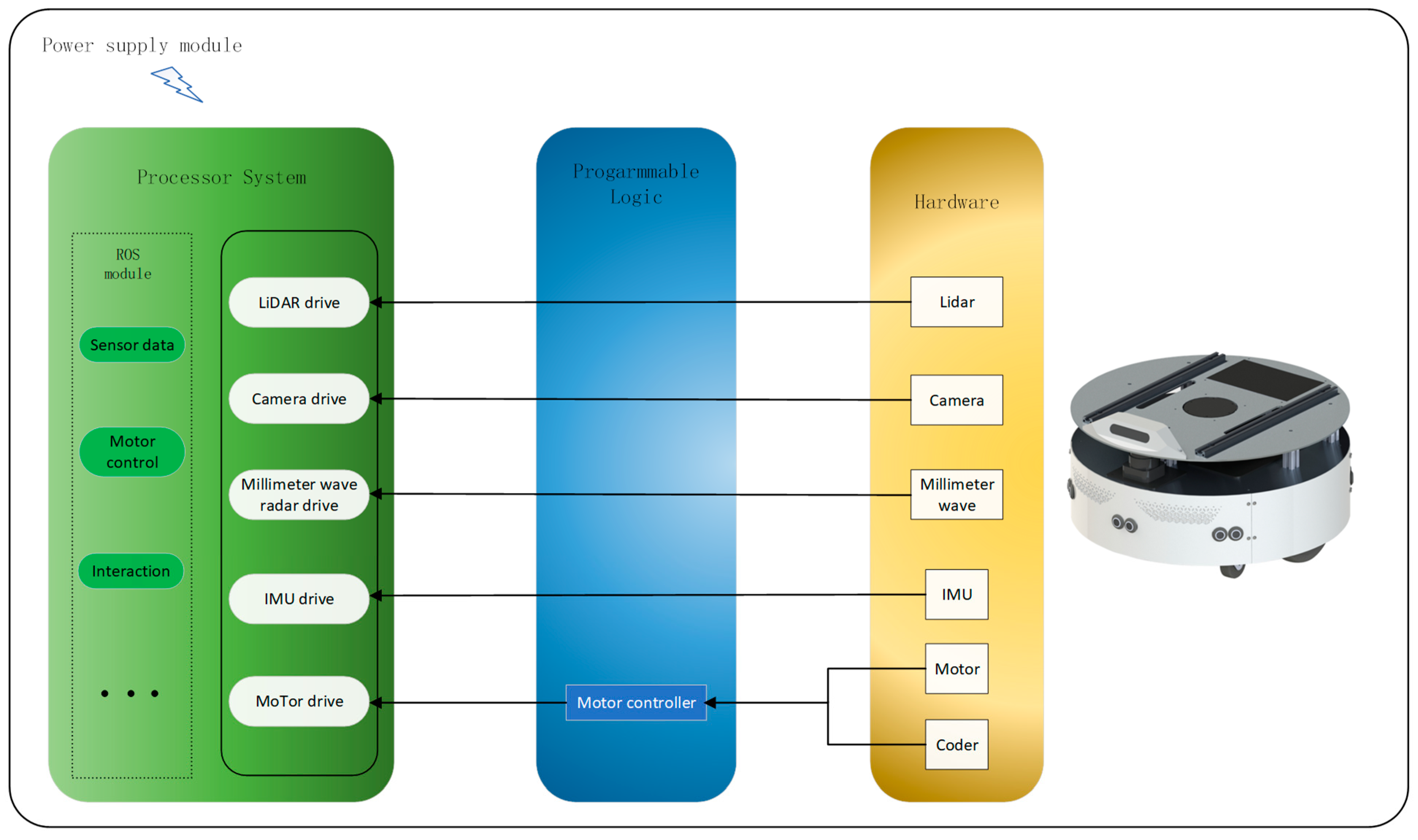
Figure 3.
Unmanned vehicle handling operation block diagram.

Figure 4.
Simplified circuit diagram of the electrostatic generator.
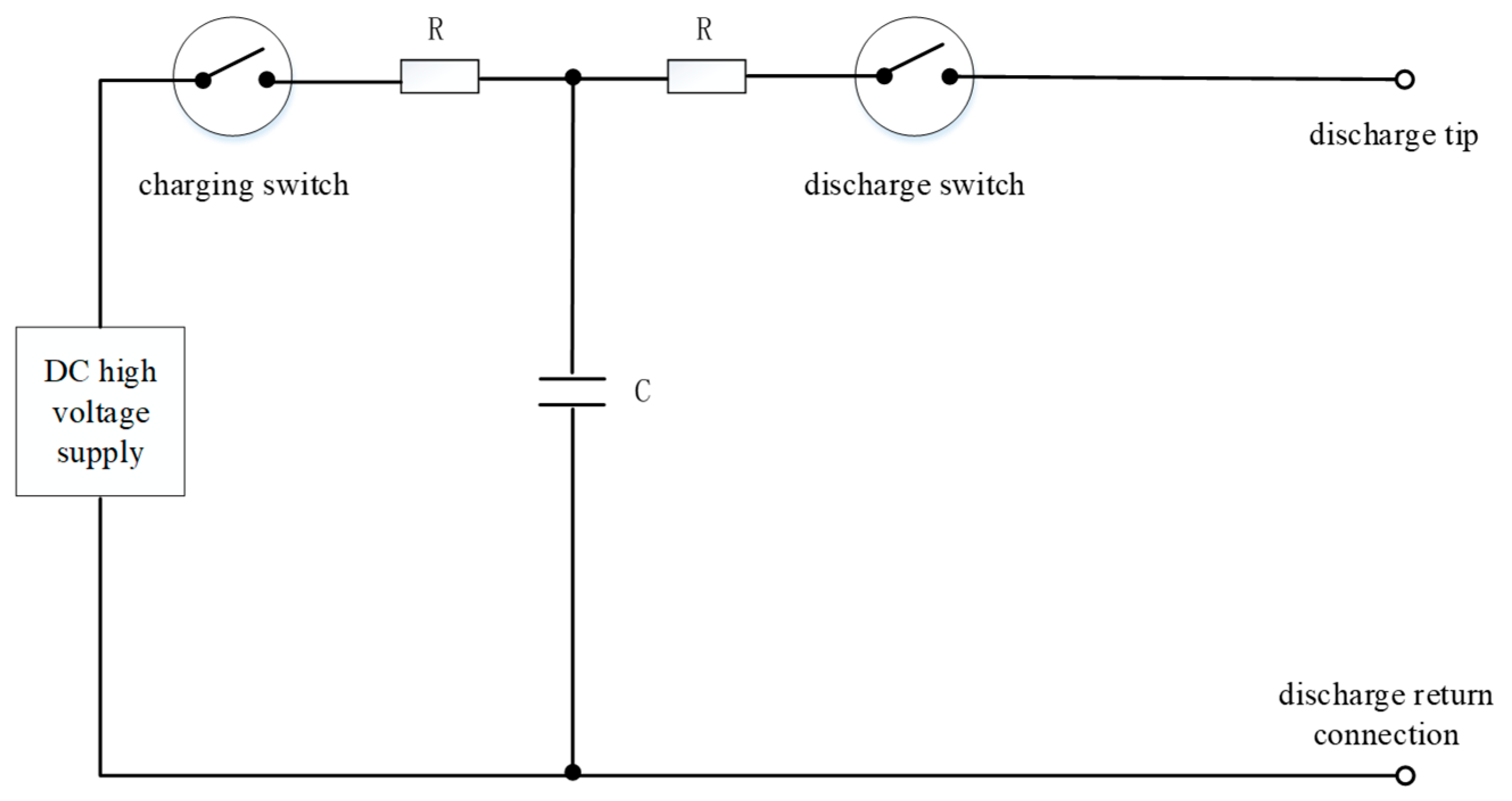
Figure 5.
Human hand ESD mode in a vehicle and human hand ESD mode outside the vehicle.

Figure 6.
Human metal ESD model in a vehicle and human metal ESD model outside the vehicle.
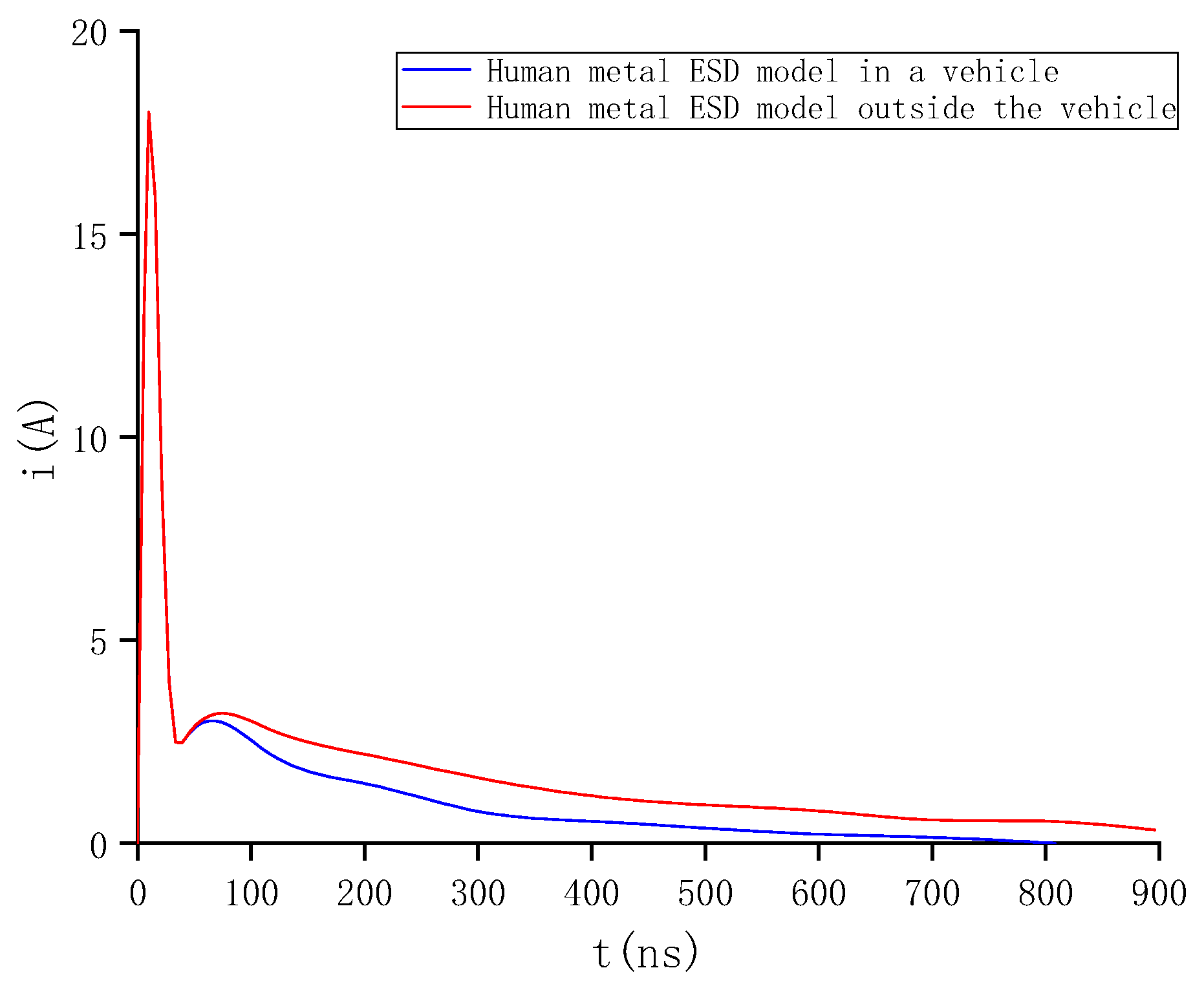
Figure 7.
ESD simulator.
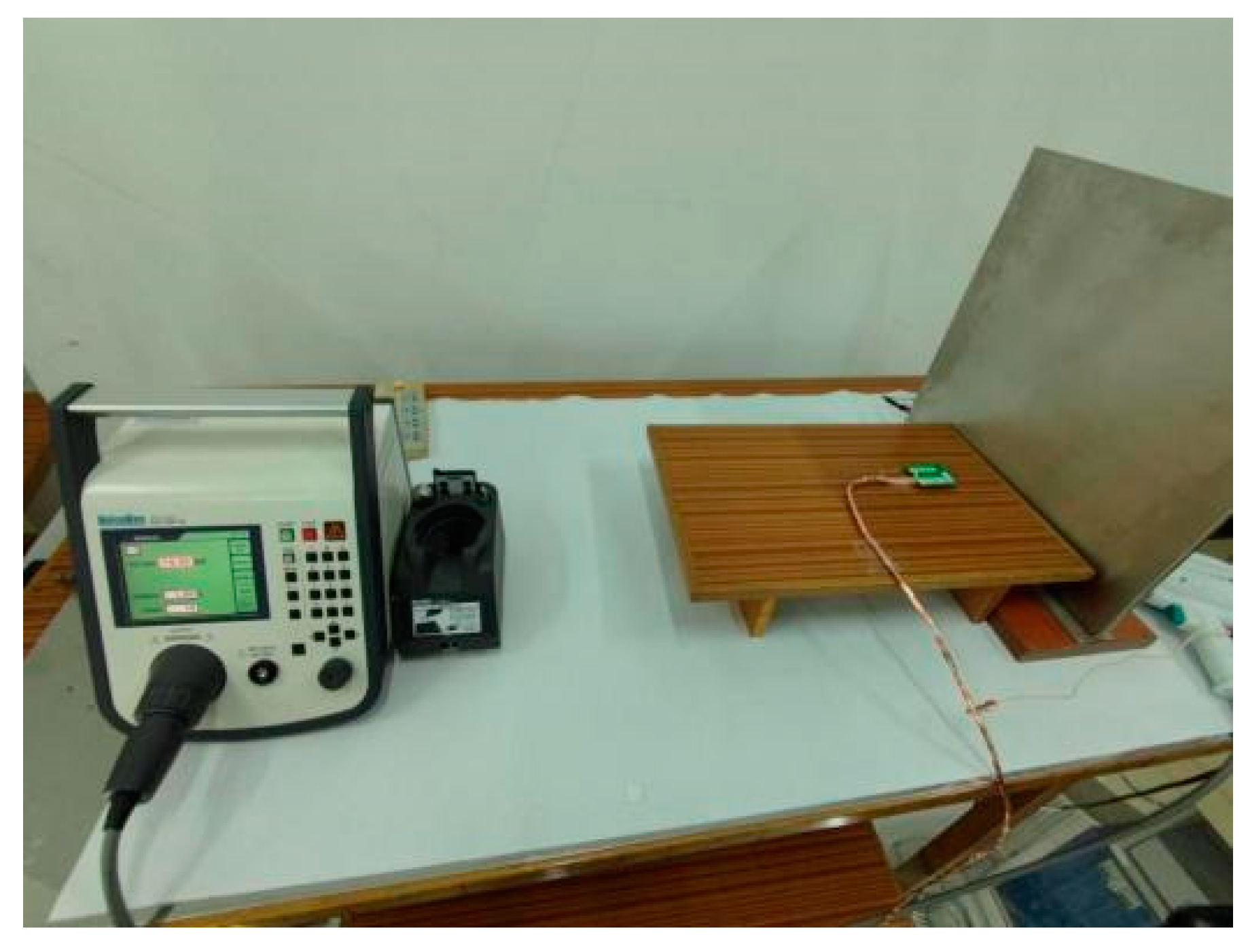
Figure 8.
Testing points for vertical coupling plate discharge.
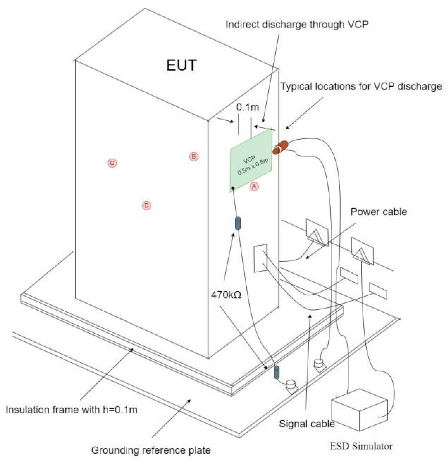
Figure 9.
Testing points for horizontal coupling plate discharge.
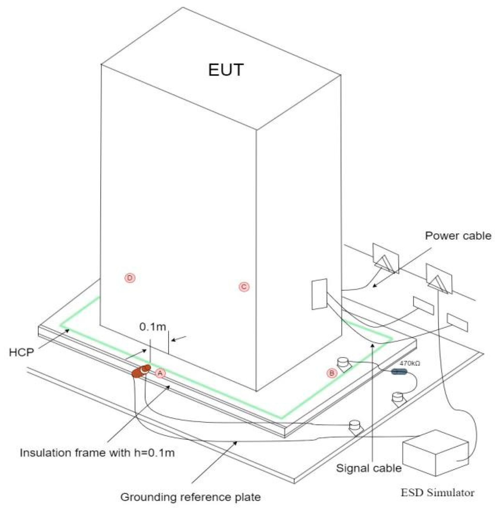
Figure 10.
LiDAR mapping: (a) normal mapping; (b) missing LiDAR data.
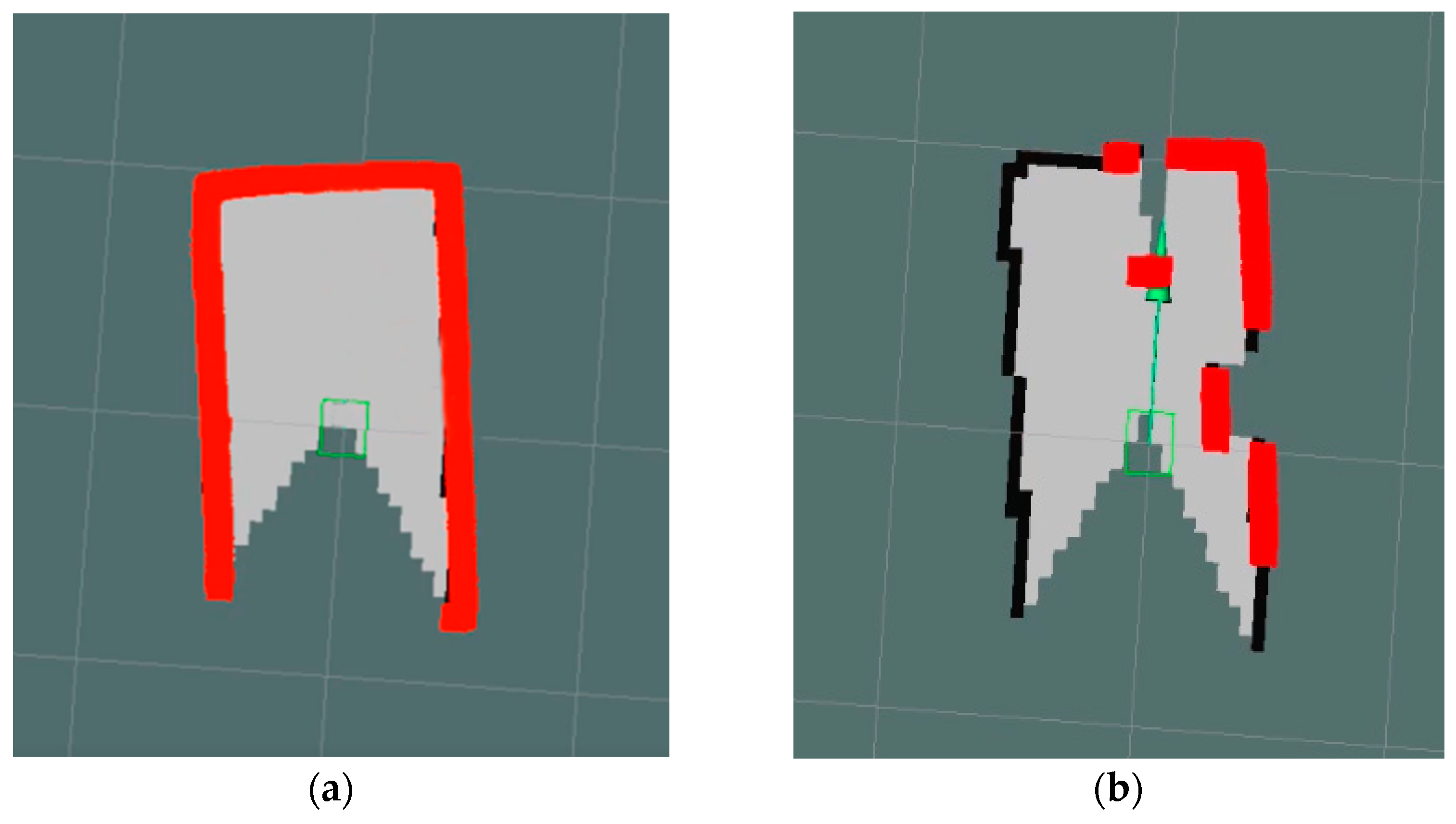
Figure 11.
Unmanned vehicle screen blurred.
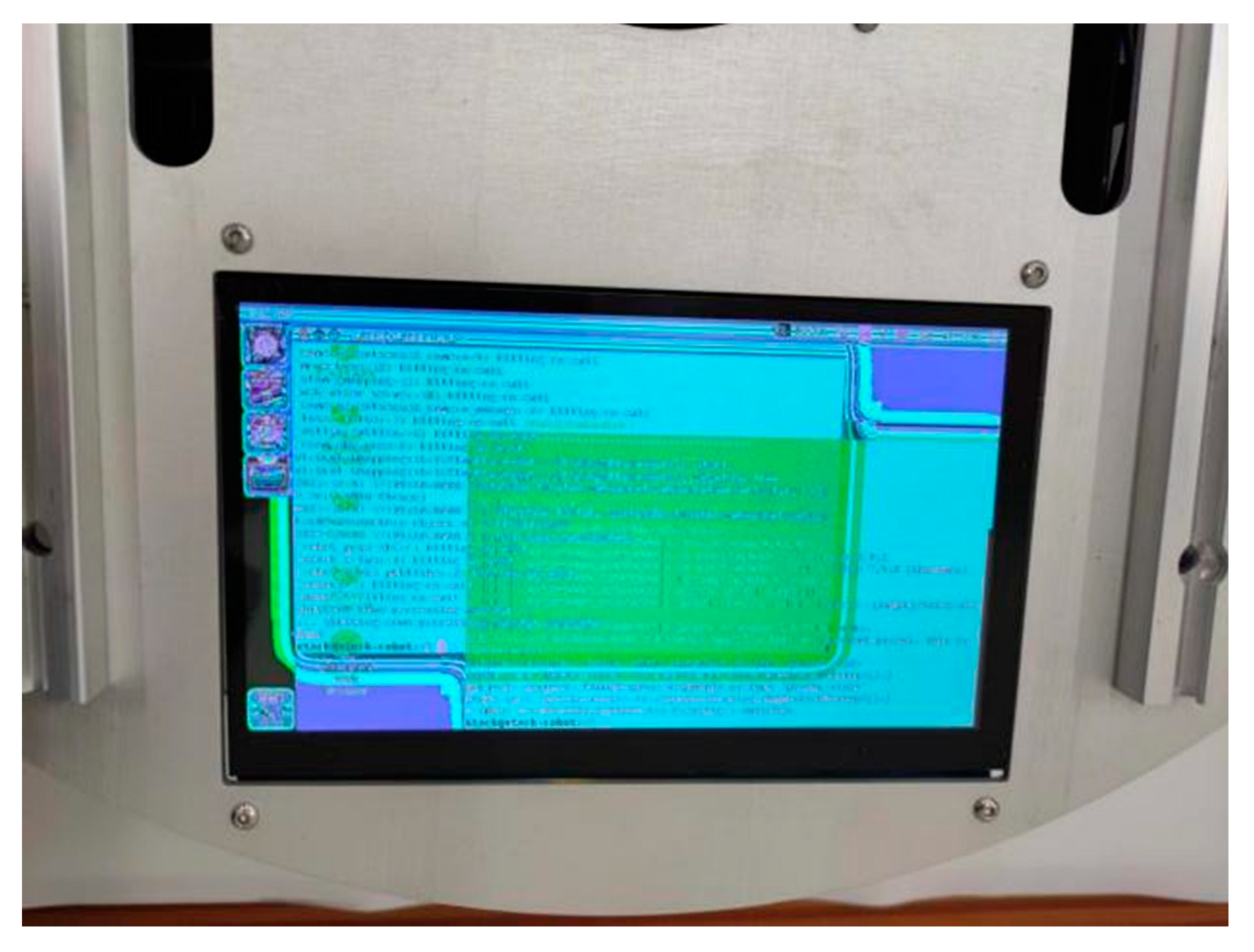
Figure 12.
LiDAR failure rate.

Table 1.
Electromagnetic compatibility standards that the perception module hardware equipment has passed.
Table 1.
Electromagnetic compatibility standards that the perception module hardware equipment has passed.
| Sensor | XT-25C Commercial LiDAR | ARS408-21 Millimeter-Wave Radar | RealSence D435 Camera |
|---|---|---|---|
| Test standards | EN 61000-6-4 IEC61000-4-6 21 CFR1040.10 | IEC61000-4-2 IEC61000-4-4 EN 301 489-1 CISPR 11 | ISO 11452-2 IEC61000-4-2 FCC Part 15B |
Table 2.
Relationships among discharge model, energy storage capacitor, and discharge resistance.
| Discharge Model | Energy Storage Capacitance (PF) | Discharge Resistance (Ω) |
|---|---|---|
| Human metal ESD model outside the vehicle | 150 | 2000 |
| Human metal ESD model in a vehicle | 330 | 2000 |
| Human hand ESD mode outside the vehicle | 150 | 330 |
| Human hand ESD mode in a vehicle | 330 | 330 |
Table 3.
Fault threshold of the unmanned vehicle handling system caused by different discharge modes and discharge models.
Table 3.
Fault threshold of the unmanned vehicle handling system caused by different discharge modes and discharge models.
| Discharge Mode | Human Hand ESD Mode Outside the Vehicle (kV) | Human Hand ESD Mode in a Vehicle (kV) | Human Metal ESD Model in a Vehicle (kV) | Human Metal ESD Model Outside the Vehicle (kV) |
|---|---|---|---|---|
| Vertical coupling plate | 6 | 6 | 6 | 8 |
| Horizontal coupling plate | 8 | 8 | 16 | 10 |
| Contact discharge | 4 | 10 | 6 | 5 |
| Air discharge | 5 | 12 | 3 | 5 |
Table 4.
Experimental data of sensing module.
| Discharge Voltage | Discharge Model | Discharge Mode | Sensing the Working State of the Module |
|---|---|---|---|
| 1 kV | Four discharge models | Four discharge modes | Normal |
| 2 kV | Four discharge models | Four discharge modes | Normal |
| 3 kV | Manikin outside the car | Air discharge | LiDAR data is temporarily missing |
| 4 kV | Human hand ESD mode outside the vehicle, Human metal ESD model in a vehicle, Human metal ESD model outside the vehicle | Air discharge, contact discharge, vertical coupling plate | LiDAR data is temporarily missing; millimeter-wave radar crashes, and it works normally after restart |
| 5 kV | Human hand ESD mode outside the vehicle | Contact discharge | LiDAR data is temporarily missing |
| 6 kV | Human hand ESD mode outside the vehicle | Contact discharge, horizontal coupling plate | The LiDAR data are seriously missing, and the obstacle location is significantly offset |
| 7 kV | Human metal ESD model outside the vehicle | Contact discharge | The LiDAR data are seriously missing, and the obstacle location is significantly offset |
| 8 kV | Human hand ESD mode outside the vehicle | Horizontal coupling plate | The LiDAR crashed and returned to normal after restart |
Table 5.
Fault threshold of EUT caused by discharge polarity.
| Discharge Mode | Positive Electrode (kV) | Negative Pole (kV) |
|---|---|---|
| Vertical coupling plate | 5 | −4 |
| Horizontal coupling plate | 6 | −10 |
| Contact discharge | 6 | −4 |
| Air discharge | 4 | −3 |
Disclaimer/Publisher’s Note: The statements, opinions and data contained in all publications are solely those of the individual author(s) and contributor(s) and not of MDPI and/or the editor(s). MDPI and/or the editor(s) disclaim responsibility for any injury to people or property resulting from any ideas, methods, instructions or products referred to in the content. |
© 2023 by the authors. Licensee MDPI, Basel, Switzerland. This article is an open access article distributed under the terms and conditions of the Creative Commons Attribution (CC BY) license (https://creativecommons.org/licenses/by/4.0/).
Share and Cite
MDPI and ACS Style
Zhang, Y.; Shen, Y.; Ma, G.; Man, M.; Liu, S. Analysis of Electrostatic Discharge Interference Effects on Small Unmanned Vehicle Handling Systems. Electronics 2023, 12, 1640. https://doi.org/10.3390/electronics12071640
AMA Style
Zhang Y, Shen Y, Ma G, Man M, Liu S. Analysis of Electrostatic Discharge Interference Effects on Small Unmanned Vehicle Handling Systems. Electronics. 2023; 12(7):1640. https://doi.org/10.3390/electronics12071640
Chicago/Turabian StyleZhang, Yongqiang, Yuejian Shen, Guilei Ma, Menghua Man, and Shanghe Liu. 2023. "Analysis of Electrostatic Discharge Interference Effects on Small Unmanned Vehicle Handling Systems" Electronics 12, no. 7: 1640. https://doi.org/10.3390/electronics12071640
Note that from the first issue of 2016, this journal uses article numbers instead of page numbers. See further details here.