
A Novel Tuning Fork-Shaped Tri-Band Planar Antenna for Wireless Applications
by
 , ,
, ,
Qiwei Li
1,2,
Jinyong Fang
2,*,
Jun Ding
1,*,
Wen Cao
3,
Jing Sun
2,
Chenjiang Guo
1 and
Tao Liu
4 1
School of Electronics and Information, Northwestern Polytechnical University, Xi’an 710129, China
2
China Academy of Space Technology (Xi’an), Xi’an 710100, China
3
School of Electronics and Control Engineering, Chang’an University, Xi’an 710064, China
4
School of Electronic Engineering, Xidian University, Xi’an 710071, China
*
Authors to whom correspondence should be addressed.
Electronics 2023, 12(5), 1081; https://doi.org/10.3390/electronics12051081
Submission received: 23 November 2022
/
Revised: 8 February 2023
/
Accepted: 17 February 2023
/
Published: 22 February 2023
(This article belongs to the Special Issue Application of Computational Electromagnetics Techniques and Artificial Intelligence in the Engineering)
Abstract
:A novel tuning fork-shaped tri-band planar antenna (NTTPA) for the LTE 2.3/3.8-GHz band, WLAN 2.4/5.2/5.8-GHz band, and WiMax 2.5/3.5/5.5-GHz band is presented in this letter. By introducing an asymmetrical turning fork-shaped patch and an inverted L-shaped patch, three notched bands can be generated to form a triple-band operation. The antenna is fabricated on an FR4 board and excited by an SMA connector using a microstrip line. The antenna structure is simple and has a compact size of 45 mm × 40 mm. The measured operating frequency covers 2.2–2.63, 2.73–3.8, and 5.13–6.3 GHz, and the percentage bandwidth is close to 53.3% (S11 < −9.8 dB from 2.2 to 3.8 GHz) and 20.5% (S11 < −10 dB from 5.13 to 6.3 GHz). The calculated and experimental results suggest that the proposed antenna is one of the best candidates for wireless communication systems in terms of multi operating bands, broad percentage bandwidth (BW), compactness, stable radiation pattern, easy processing, and low cost.
1. Introduction
In recent years, wireless communication technology has made great achievements and has been widely used in all kinds of electronic equipment. The antenna, which plays a key role in wireless communication systems, should be capable of operating at multi-frequencies simultaneously. The microstrip antenna is an attractive candidate for wireless applications, owing to its characteristics of low profile, low cost, easy processing, and manufacturing [1,2].
Over the past decades, numerous microstrip patch antennas with multi operating frequencies have been reported on for wireless communication, particularly for Long Term Evolution (LTE 2.3/3.8-GHz), wireless local area networks (WLAN 2.4/5.2/5.8-GHz), and worldwide interoperability for microwave access (WiMAX 2.5/3.5/5.5-GHz). These include asymmetric m-shaped antennas with vias [3], dielectric-loaded monopoles with shorted loops [4], proximity-coupled dual-substrate antennas with corner-truncated rectangular patches and defected ground planes [5], dumb-bell-shaped defected structure monopoles [6], open slot antennas [7], uniplanar dipole complementary capacitively loaded loop (CCLL) slots [8], rectangular ring monopoles with fork-shaped strips [9], dipoles with two electrical shorts and reflecting ground planes [10], D-shaped monopoles [11], patch antennas with inner patches and outer rings [12], and multi feed antennas [13,14,15,16] covering different wireless frequencies. The majority of the designs mentioned above only cover parts of the bands of LET, WLAN, and WiMax [3,4,5,6,7,9,12,13,14,15,16,17,18,19,20,21,22,23,24,25]. The designs are in the references. The examples in [8,10,11] can basically meet all frequency band requirements, but these antennas have a relatively large size. Hence, it is a huge challenge to design a multiband microstrip antenna not only covering the all the LTE (2.3–2.4, 3.6–3.8 GHz), WLAN (2.4–2.484, 5.15–5.35, 5.725–5.825 GHz), and WiMAX (2.5–2.69, 3.4–3.69, 5.25–5.85 GHz) bands but also maintaining a compact size.
This letter presents a novel tuning fork-shaped tri-band planar antenna (NTTPA) for LTE (2.3/3.8-GHz), WLAN (2.4/5.2/5.8-GHz), and WiMAX (2.5/3.5/5.5-GHz) applications. The proposed antenna is composed of an asymmetrical turning fork-shaped patch and an inverted L-shaped patch connected to the middle of an rectangular ground, which can achieve a good performance of multi operation bands, enhanced percentage bandwidth, stable radiation patterns at different operating bands, and low cost. The proposed antenna has a compact size of 45 mm × 40 mm and is much smaller than [8,10,11]. That is to say, the antenna mentioned in Table 1 and in this paper can keep good performance in three frequency bands while realizing the miniaturization of size. The details of the design, parameter studies, and calculated and experimental results such as RL characteristics, surface current distributions, radiation patterns, and gains are also discussed and presented in the following chapters.
2. Antenna Topology
The geometry of the proposed novel tuning fork-shaped tri-band planar antenna (NTTPA), including the top view, side view, and bottom view, is depicted in Figure 1. The proposed NTTPA is fabricated on a single-layer FR4 substrate with a height of h = 1.6 mm, a relative dielectric constant of 4.4, and a loss tangent of 0.02. As shown in Figure 1, the proposed NTTPA is composed of an asymmetrical tuning fork-shaped patch and an inverted L-shaped monopole combined with a rectangular ground plane fed by an SMA connector using a microstrip line. Table 2 displays the overall dimensions of the proposed antenna. To facilitate processing, all line widths are designed to be the same W = 3 mm.
3. Theory and Design
Here, in this section, geometrical progress to achieve the proposed antenna design is outlined as shown in Figure 2. In the beginning, a simple monopole strip is printed on the upper surface of the FR-4 substrate whose one end is connected with SMA connector, as shown in Figure 2a. To achieve omnidirectional operating characteristics in the XOZ plane, a partial ground plane is taken on backside of the substrate (Ant. I).
For a microstrip monopole on a substrate, the wave is transmitted through both the medium and free space, thus the actual wavelength should be between the conduction wavelength of the medium and the operating wavelength of the free space. In this case, the electrical length Lm of the microstrip monopole can be calculated by [28,29]:
where c is the speed of light, is the operating frequency, h is the thickness of the substrate, is the dielectric constant of the substrate, and Wm is the width of the monopole.
According to Equation (1), in order to cover the operating band of 2.2 GHz, the electrical length Lm of the microstrip monopole should be between 17.5 mm and 34.1 mm. At the same time, the antenna’s higher-order operating mode should also cover 5.5 GHz frequency points. We optimized the parameters of the monopole in the CST simulator to meet both of the above requirements. The final values of Lm and Wm were 34 mm and 3 mm, respectively, and the dimension of the partial ground plane was 40 × 11 mm2. Figure 3 shows the surface current distribution of the antenna under two different operating modes, including the surface current Jsm1, Jsg1, Jsg2 in low-order operating mode and the surface current Jsm2, Jsm3, Jsg3, Jsg4 in high-order operating mode. Due to the symmetrical structure of antenna I, Jsg1 and Jsg2 present mirror image distribution and so does Jsg3 and Jsg4. It can be seen that the path length of Jsm1 was about twice that of Jsm2, and the path length of Jsg1 was more than twice as much as that of Jsg3. Therefore, the frequency of the antenna in high-order mode should be more than twice that in low-order mode and higher than 4.4 GHz. The analysis results were consistent with the simulation results in Figure 4. We can see that the proposed monopole antenna (Ant I) operated at 2.22 GHz (2.1–2.34 GHz, S11 = −12.9 dB) and 5.51 GHz (5.34–5.73 GHz, S11 = −24.8 dB). This fabricated prototype showed good dual frequency performance and a simple structure, but its drawback was that the operating frequency did not fully cover the 5.25 GHz bands. If we optimize the antenna structure so that its high-frequency operating band covers 5.25 GHz, the volume of the antenna will increase, and we will need to change the antenna’s prototype.
Then, the monopole strip (Ant. I) is converted to a symmetrical turning fork-shaped patch antenna (STPA) with a rectangular ground, which is referred to Ant. II, shown in Figure 2b. One advantage of the dual-L-shaped design is that the L-shaped structure can increase the equivalent electrical length of the antenna in a finite volume, which will make the operating frequency of the antenna move to the low frequency band. Additionally, the dual-L structure is equivalent to a double element array, which can effectively enhance the radiation of the antenna and improve the S11 characteristics of the antenna. To make the comparison more meaningful and simplify the design process, we adopted the following principles: (1) the overall dimensions and ground size of the STPA shall be consistent with the design of Ant. I; (2) only the length of L4 was changed to optimize the operating frequency band of STPA, while keeping other parameters constant. According to the above design principles, the parameters were designed as follows: L1 = 12 mm, L2 = L3 = 6.5 mm, L6 = 11 mm. Then, we optimized the operating frequency band of the antenna by adjusting the length of L4 and L5 in the U-shaped structure (L4 = L5).
Figure 5 shows the change in |S11| over the operating frequency range for step 2 with the change in L4. It can be seen that the operating band always decreased significantly with the increasing L4. When the length of L4 was equal to 16 mm, this design had a good wideband characteristic with an impedance BW (S11 < −10 dB) covering 3.22–6.54 GHz, which covered the LTE (3.8-GHz), WLAN (5.2/5.8-GHz) and WiMAX (3.5/5.5-GHz) bands. Furthermore, the S11 at the resonant point of the antenna was almost better than −30 dB, which verified the radiation-enhanced effect of the double-L structure proposed above.
Figure 6 exhibits the simulated radiation patterns of the proposed STPA at two orthogonal cut planes. The calculated gains were 3.7, 5.5, and 5.9 dBi at 3.5, 5.2, and 5.8 GHz, respectively. It was concluded that the STPA antenna could meet most frequency bands of LTE, WLAN, and WiMAX applications based on the S11 characteristics and radiation direction characteristics. However, it’s worth noting that this design misses the LTE (2.3-GHz), WLAN (2.4-GHz), and WiMAX (2.5-GHz) bands. It is possible to further increase the length of L4 to cover 2.3~2.5 GHz, but this approach will cause the operating band to shift to lower frequencies and miss the high frequency point of the operating band, as the green line (L4 = 20 mm) shows in Figure 5.
In order to improve its return loss of low frequency (2–3 GHz), we take the method of asymmetric designing and only increase the length of L5, which can not only broaden the operating band by Superposition of resonant frequency points but also avoids the whole band moving to the low frequency region caused by increasing the length of both sides (L4 and L5). Thus, the symmetrical turning fork-shaped patch antenna (STPA) evolves into the asymmetrical turning fork-shaped patch antenna (ATPA).
Figure 7 shows the change in |S11| over the operating frequency range with the change in L5 of the new design. It can be seen that the ATPA prototype shows the excellent characteristics of ultra-wideband. When the L5 is optimized and properly selected as 26 mm, the ATPA achieves a −10 dB bandwidth of 5.05 GHz (2.95–7 GHz), which is enough for the majority of frequency points of wireless application. Figure 8 illustrates the calculated radiation patterns of the ATPA (L5 = 26 mm) in the xoz and yoz planes under 2.4, 3.5, 5.2, and 5.8 GHz, and the corresponding simulated gains (L5 = 26 mm) can reach 1.37, 3.62, 4.84, and 4.76 dBi, respectively. In the xoz plane, the radiation pattern is omnidirectional at 2.4, 3.5, and 5.2 GHz and shows a little bit of inomnidirectivity at 5.8 GHz. It can be seen that the radiation patterns are comparatively stable within the operating band and the same to radiation patterns in the yoz plane, which is convenient for the practical application.
The only drawback is that the S11 around 2.4 GHz only reaches −2.92 dB and still needs to be improved. What we should be concerned about is that continuing to increase the electrical length may enhance its low-frequency transmission characteristics, but it will result in a larger antenna size, which is clearly not an optimal approach. Thus, we need to find a new path to solve it.
For the ATPA, there are two main current paths on either side of the asymmetric tuning fork structure, the equivalent electrical lengths of which are approximately equal to (L2 + L4) and (L3 + L5), respectively. According to the formula [17]: f = c/4 L (c is the speed of light in free space; and L is the electrical length.), it can be calculated that the two resonant points of the antenna are about 2.31 and 3.3 GHz, which are consistent with the simulation results in Figure 7. Therefore, we need to design a new current path with a length between 22.5 mm and 32.5 mm to enhance the low frequency resonance characteristics. However, the return loss only reaches −10 dB in the range of 5 to 6 GHz, and thus the introduction of a new structure is likely to worsen the return loss in this range. Thus, we need to subtly design a new structure, which could not only improve the reflection characteristics of both low and high frequency regions but also maintain the current size.
Based on the analysis above, we proposed a novel tuning fork-shaped tri-band planar antenna (NTTPA) by meticulously adding an inverted L-shaped radiation patch on the ground of the ATPA. In addition, the L-shaped patch is designed on the short side of the turning fork-shaped patch to compensate for the radiation asymmetry caused by the asymmetric turning fork structure. The antenna is optimized by adjusting L7 and L8, and the final structure size is shown in Table 1.
The simulated surface current distributions under 2.4 and 5.8 GHz are given in Figure 9 to illustrate the operating mechanism for the ATPA and NTTPA. The larger value of the current distribution is indicated in red, and the smaller value is in blue. It can be seen that the introduction of the inverted L-shaped structure not only provides a new current path but also enhances the circuit density in the existing paths on the asymmetric turning fork patch. Additionally, the same effect could be observed at 5.8 GHz.
Figure 10 illustrates the S11 characteristic of different designs from the microstrip monopole to the NTTPA (Antenna I refers to the monopole, Antenna II refers to the STPA, Antenna III refers to the ATPA, and Antenna IV refers to the NTTPA). It is obvious that the addition of inverted L-shaped structures reduces the low frequency return loss, which is consistent with the above analysis above. The simulation results shows that −10 dB bandwidth of the proposed novel tuning fork-shaped tri-band patch antenna (NTTPA) covers 2.28–3.7 and 4.7–6.2 GHz, which is enough for LTE (2.3–2.4, 3.6–3.8), WLAN (2.4–2.484, 5.15–5.35, 5.725–5.825), and WiMAX (2.5–2.69, 3.4–3.69, 5.25–5.85) applications.
4. Results and Discussion
To confirm the predicted radiation-enhanced and multiband operating characteristics exhibited in Figure 9 and Figure 10, a novel tuning fork-shaped tri-band planar antenna (NTTPA) was fabricated and tested. The physical picture of the proposed antenna is shown in Figure 11. The performance of the proposed antenna was tested in an anechoic chamber, shown in Figure 12, including return loss, gain, and radiation pattern. The measured return loss tested by Agilent vector network analyzer-E8363B was compared by the simulation results. As shown in Figure 13, a strong agreement was observed. The measured impedance BW over −10 dB was 17.8% (2.2–2.63 GHz), 32.8% (2.73–3.8 GHz), and 20.5% (5.13–6.3 GHz), and the maximum value could reach −20.9 dB (at 2.42 GHz), −24.5 dB (at 3.29 GHz), and −23.1 dB (at 5.98 GHz). It can be noted that the −9.8 dB impedance BW covered 2.2–3.8 GHz with a percentage BW of 53.3%.
Figure 14 shows the calculated and measured gains for the proposed antenna. The measured ranges of the antenna gains were 0.8–1.9, 2–3.6, and 4.7–5.6 dBi in Band-I (2.2–2.63 GHz), band-II (2.73–3.8 GHz), and band-III (5.13–6.3 GHz), respectively. Small variations were observed between calculated and test results for both bands, which can be attributed to possible cable effect and tolerance in measurement.
Figure 15 shows the normalized radiation patterns at 2.4, 3.5, 5.2, and 5.8 GHz, respectively. The difference between the simulated and experimental results was small. We can see that the proposed NTTPA showed good omnidirectional radiation property in the xoz plane and directional radiation property in the yoz plane. It is worth noting that the radiation direction of the antenna was very close at a different frequency, which is very conducive to the industrial application. The efficiency and front-to-back ratio plots are displayed in Figure 16 and Figure 17, respectively. Compared with the same tri-band antenna in the references, the S11 proposed in this paper is lower [19,20].
5. Conclusions
A novel tuning fork-shaped tri-band planar antenna (NTTPA) for LTE (2.3/3.8-GHz), WLAN (2.4/5.2/5.8-GHz), and WiMAX (2.5/3.5/5.5-GHz) applications has been successfully reported with a compact size of 45 mm × 40 mm. The evolution of achieving this proposed antenna has been discussed in detail. The antenna mentioned in this paper can keep good performance in three frequency bands while realizing the miniaturization of its size. It has a wide bandwidth and a high gain, relatively. Besides exhibiting desirable impedance BW and overall size, the proposed antenna has also shown very stable radiation patterns across the three bands of interest, which is suitable for wireless communication applications. At the same time, it also provides useful inspiration for 5G antenna designs. Work can be performed in the future to further realize miniaturization.
Author Contributions
Data curation, J.D. and J.S.; Funding acquisition, W.C.; Investigation, Q.L.; Methodology, Q.L. and C.G.; Resources, J.F.; Supervision, J.D.; Visualization, W.C. and T.L.; Writing original draft, Q.L.; Writing review and editing, J.F., J.D. and T.L. All authors have read and agreed to the published version of the manuscript.
Funding
This work was supported by the Foundation Enhancement Plan (2017-JCJQ-ZD-02), National Key Laboratory of Science and Technology on Space Microwave (No: 6142411332211), the National Natural Science Foundation of China (61803042), and the Fundamental Research Funds for the Central Universities, CHD (300102322103).
Data Availability Statement
Not applicable.
Conflicts of Interest
The authors declare no conflict of interest.
References
- Carver, K.; Mink, J. Microstrip antenna technology. IEEE Trans. Antennas Propag. 1981, 29, 2–24. [Google Scholar] [CrossRef]
- Dey, S.; Mittra, R. Compact microstrip patch antenna. Microw. Opt. Technol. Lett. 1996, 13, 12–14. [Google Scholar] [CrossRef]
- Li, J.; Guo, J.; He, B.; Zhang, A.; Liu, Q.H. Tri-band CPW-fed stub-loaded slot antenna design for WLAN/WiMAX applications. Frequenz 2016, 70, 521–526. [Google Scholar] [CrossRef]
- Yildirim, B.; Basaran, E.; Turetken, B. Dielectric-Loaded Compact WLAN/WCDMA Antenna With Shorted Loop and Monopole Elements. IEEE Antennas Wirel. Propag. Lett. 2013, 12, 288–291. [Google Scholar] [CrossRef]
- Bakariya, P.S.; Dwari, S.; Sarkar, M.; Mandal, M.K. Mandal. Proximity-coupled multiband microstrip antenna for wireless applications. IEEE Antennas Wirel. Propag. Lett. 2015, 14, 646–649. [Google Scholar] [CrossRef]
- Malik, J.; Patnaik, A.; Kartikeyan, M.V. A Compact Dual-Band Antenna With Omnidirectional Radiation Pattern. IEEE Antennas Wirel. Propag. Lett. 2015, 14, 503–506. [Google Scholar] [CrossRef]
- Li, W.-W.; Li, Q.-H.; Meng, Y.; Wang, J.-Y.; Xu, W.-M. A broadband microstrip patch antenna with multiple open slots. Microw. Opt. Technol. Lett. 2019, 61, 626–632. [Google Scholar] [CrossRef]
- Sim, C.Y.D.; Chen, H.D.; Yeh, C.H.; Lin, H.L. Small size triple band monopole antenna with a parasitic element. Microw. Opt. Technol. Lett. 2015, 57, 342–348. [Google Scholar] [CrossRef]
- Li, L.; Zhang, X.; Yin, X.; Zhou, L. Compact Triple-Band Printed Monopole Antenna for WLAN/WiMAX Applications. IEEE Antennas Wirel. Propag. Lett. 2016, 15, 1853–1855. [Google Scholar] [CrossRef]
- van Rooyen, M.; Odendaal, J.W.; Joubert, J. High-Gain Directional Antenna for WLAN and WiMAX Applications. IEEE Antennas Wirel. Propag. Lett. 2017, 16, 286–289. [Google Scholar] [CrossRef] [Green Version]
- Liu, G.; Liu, Y.; Gong, S. Compact tri-band wide-slot monopole antenna with dual-ring resonator for WLAN/WiMAX applications. Microw. Opt. Technol. Lett. 2016, 58, 1097–1101. [Google Scholar] [CrossRef]
- Yang, X.; Ji, Y.; Ge, L.; Zeng, X.; Wu, Y.; Liu, Y. A dual-band radiation-differentiated patch antenna for future wireless scenes. IEEE Antennas Wirel. Propag. Lett. 2020, 19, 1007–1011. [Google Scholar] [CrossRef]
- Feng, S.; Zhang, L.; Yu, H.-W.; Zhang, Y.-X.; Jiao, Y.-C. A Single-Layer Wideband Differential-Fed Microstrip Patch Antenna With Complementary Split-Ring Resonators Loaded. IEEE Access 2019, 7, 132041–132048. [Google Scholar] [CrossRef]
- Li, W.; Xia, Z.; You, B.; Liu, Y.; Liu, Q.H. Dual-Polarized H-Shaped Printed Slot Antenna. IEEE Antennas Wirel. Propag. Lett. 2017, 16, 1484–1487. [Google Scholar] [CrossRef]
- Yang, X.; Kong, F.; Liu, X.; Song, C. A CPW-fed triple-band antenna for WLAN and WiMAX applications. Radioengineering 2014, 23, 1086–1091. [Google Scholar]
- Chaturvedi, D.; Kumar, A.; Raghavan, S. An integrated SIW cavity-backed slot antenna-triplexer. IEEE Antennas Wirel. Propag. Lett. 2018, 17, 1557–1560. [Google Scholar] [CrossRef]
- Mao, X.; Zhu, Y.; Li, Y. A Simple Tri-Band Proximity Coupling Fed Compact Antenna for 2.7GHz, WLAN and Sub-6GHz Communication Applications. In Proceedings of the 2018 IEEE International Symposium on Antennas and Propagation & USNC/URSI National Radio Science Meeting, Boston, MA, USA, 8–13 July 2018; pp. 1013–1014. [Google Scholar]
- Boutejdar, A.; Halim, B.I. Design of a Compact Tri-band Ring Antenna Using Two Parasitic Ring Resonators and Partial Ground Plane for WiMAX and RADAR Applications. In Proceedings of the 2019 IEEE International Electromagnetics and Antenna Conference (IEMANTENNA), Vancouver, BC, Canada, 17–19 October 2019; pp. 51–55. [Google Scholar]
- Kiani, S.H.; Khan, M.A.; Rafique, U.; Marey, M.; Alharbi, A.G.; Mostafa, H.; Khan, M.A.; Abbas, S.M. High Performance Eight-Port Dual-Band MIMO Antenna System for 5G Devices. Micromachines 2022, 13, 959. [Google Scholar] [CrossRef] [PubMed]
- Kiani, S.H.; Marey, M.; Savci, H.; Mostafa, H.; Rafique, U.; Khan, M.A. Dual-Band Multiple-Element MIMO Antenna System for Next-Generation Smartphones. Appl. Sci. 2022, 12, 9694. [Google Scholar] [CrossRef]
- Zahid, M.N.; Gaofeng, Z.; Kiani, S.H.; Rafique, U.; Abbas, S.M. H-Shaped Eight-Element Dual-Band MIMO Antenna for Sub-6 GHz 5G Smartphone Applications. IEEE Access 2022, 10, 85619–85629. [Google Scholar] [CrossRef]
- Malallah, R.; Shaaban, R.M.; Al-Tumah, W.A.G. A dual band star-shaped fractal slot antenna: Design and measurement. AEU-Int. J. Electron. Commun. 2020, 127, 153473. [Google Scholar] [CrossRef]
- Haque, S.M.; Alam, H. Miniaturized dual-band slot antenna design for GPS, amateur radio and WLAN applications. Int. J. RF Microw. Comput.-Aided Eng. 2020, 30, e22125. [Google Scholar] [CrossRef]
- Madhav, B.T.P.; Monika, M.; Kumar, B.M.S.; Prudhvinadh, B. Dual band reconfigurable compact circular slot antenna for WiMAX and X-band applications. Radioelectron. Commun. Syst. 2019, 62, 474–485. [Google Scholar] [CrossRef]
- Madhavi, D.; Jagadeesh, D. Dual-band semi-hexagonal slot antenna backed by SIW for WLAN/WBAN applications. Prog. Electromagn. Res. C 2022, 121, 221–232. [Google Scholar] [CrossRef]
- Kumar, A.; Jhanwar, D.; Sharma, M.M. A compact printed multistubs loaded resonator rectangular monopole antenna design for for multiband wireless systems. Int. J. RF Comput. Aided Eng. 2017, 27, e21147. [Google Scholar] [CrossRef]
- Kumar, A.; Jhanwar, D.; Sharma, M.M. Miniaturized multistubs loaded rectangular loaded monopole antenna for multiband applications based on theory of characteristics modes. Prog. Electromag. Res. C 2019, 92, 177–189. [Google Scholar] [CrossRef] [Green Version]
- Balanis, C.A. Antenna Theory: Analysis and Design; Wiley: New York, NY, USA, 2005. [Google Scholar]
- Ghouz, H.H.M.; Sree, M.F.A.; Ibrahim, M.A. Novel Wideband Microstrip Monopole Antenna Designs for WiFi/LTE/WiMax Devices. IEEE Access 2020, 8, 9532–9539. [Google Scholar] [CrossRef]
Figure 1.
Geometrical design of the proposed antenna. (a) Top view. (b) Side view. (c) Bottom view.

Figure 2.
Evolution stages of the proposed antenna.

Figure 3.
Surface current of the proposed monopole (Ant. I): (a) low-order mode; (b) high-order mode.
Figure 3.
Surface current of the proposed monopole (Ant. I): (a) low-order mode; (b) high-order mode.
Figure 4.
Simulated reflection coefficient of the proposed antenna I in Figure 2 (Lm = 34 mm, Wm = 3 mm).
Figure 4.
Simulated reflection coefficient of the proposed antenna I in Figure 2 (Lm = 34 mm, Wm = 3 mm).
Figure 5.
Simulated reflection coefficient of the STPA as a function of microstrip-line length L4.
Figure 6.
Simulated radiation patterns of the proposed STPA at (a) xoz-plane, (b) yoz-plane.
Figure 7.
Simulated reflection coefficient of the ATPA as a function of microstrip-line length L5. (L1 = 12 mm, L2 = L3 = 6.5 mm, L4 = 16 mm, L6 = 11 mm, 45 × 40 mm2).
Figure 7.
Simulated reflection coefficient of the ATPA as a function of microstrip-line length L5. (L1 = 12 mm, L2 = L3 = 6.5 mm, L4 = 16 mm, L6 = 11 mm, 45 × 40 mm2).
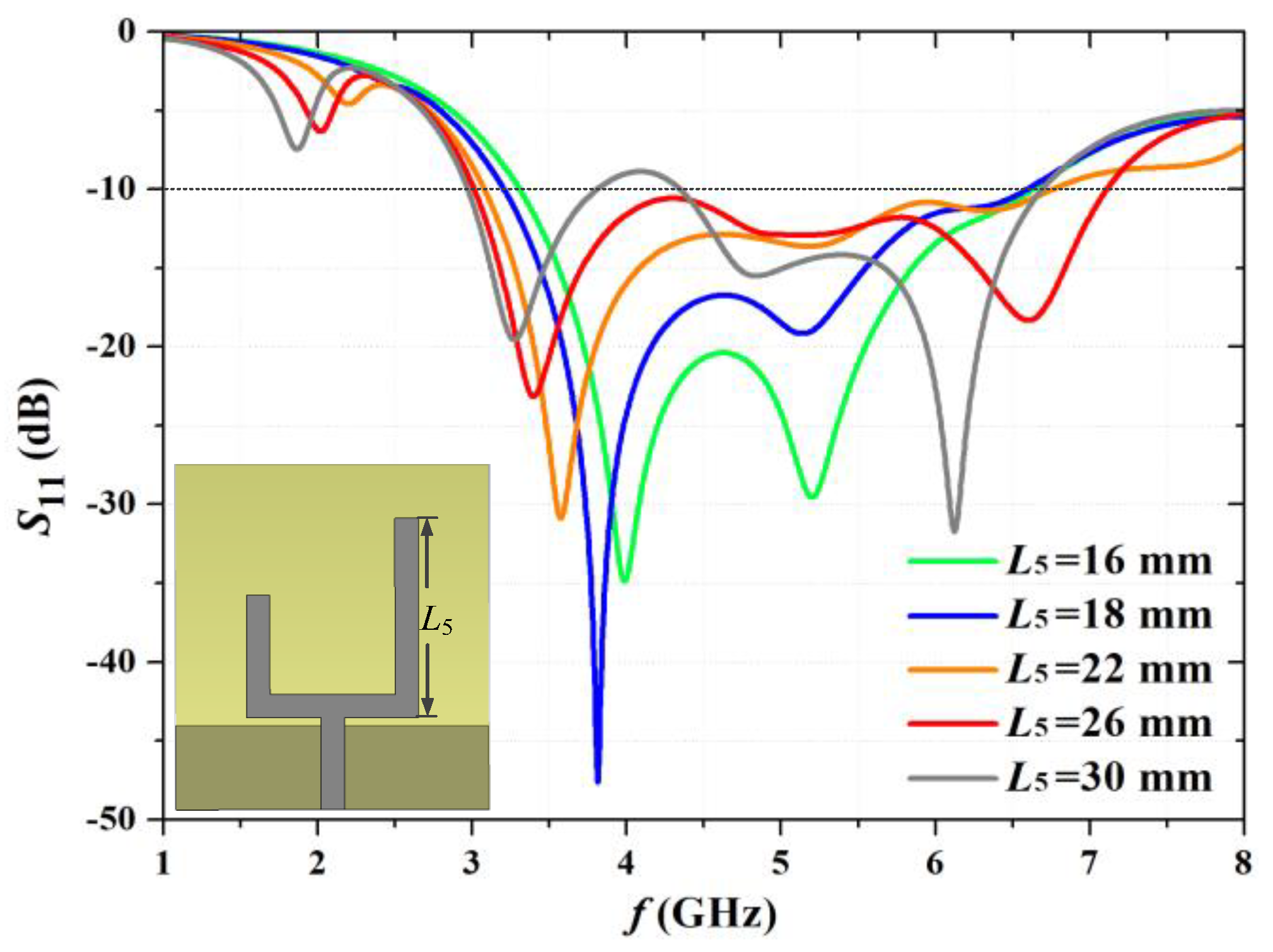
Figure 8.
Simulated radiation patterns of the proposed ATPA at (a) xoz-plane, (b) yoz-plane.
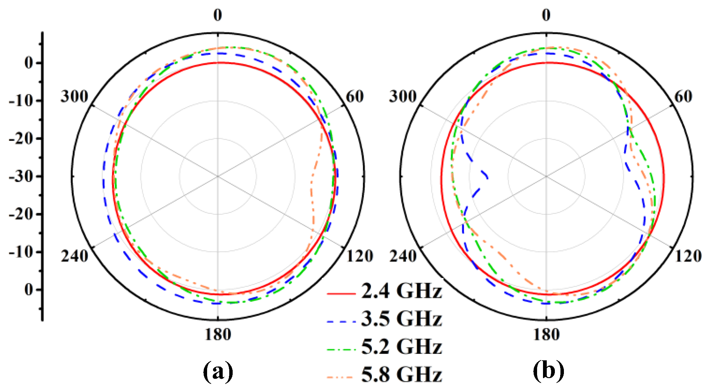
Figure 9.
Simulation results of the surface current distributions. (a) ATPA at 2.4 GHz. (b) NTTPA at 2.4 GHz. (c) ATPA at 5.8 GHz. (d) NTTPA at 5.8 GHz.
Figure 9.
Simulation results of the surface current distributions. (a) ATPA at 2.4 GHz. (b) NTTPA at 2.4 GHz. (c) ATPA at 5.8 GHz. (d) NTTPA at 5.8 GHz.

Figure 10.
Simulated reflection coefficient of different proposed antenna.

Figure 11.
The physical picture of the proposed antenna.

Figure 12.
Calculated and experimental S11 of the proposed NTTPA.
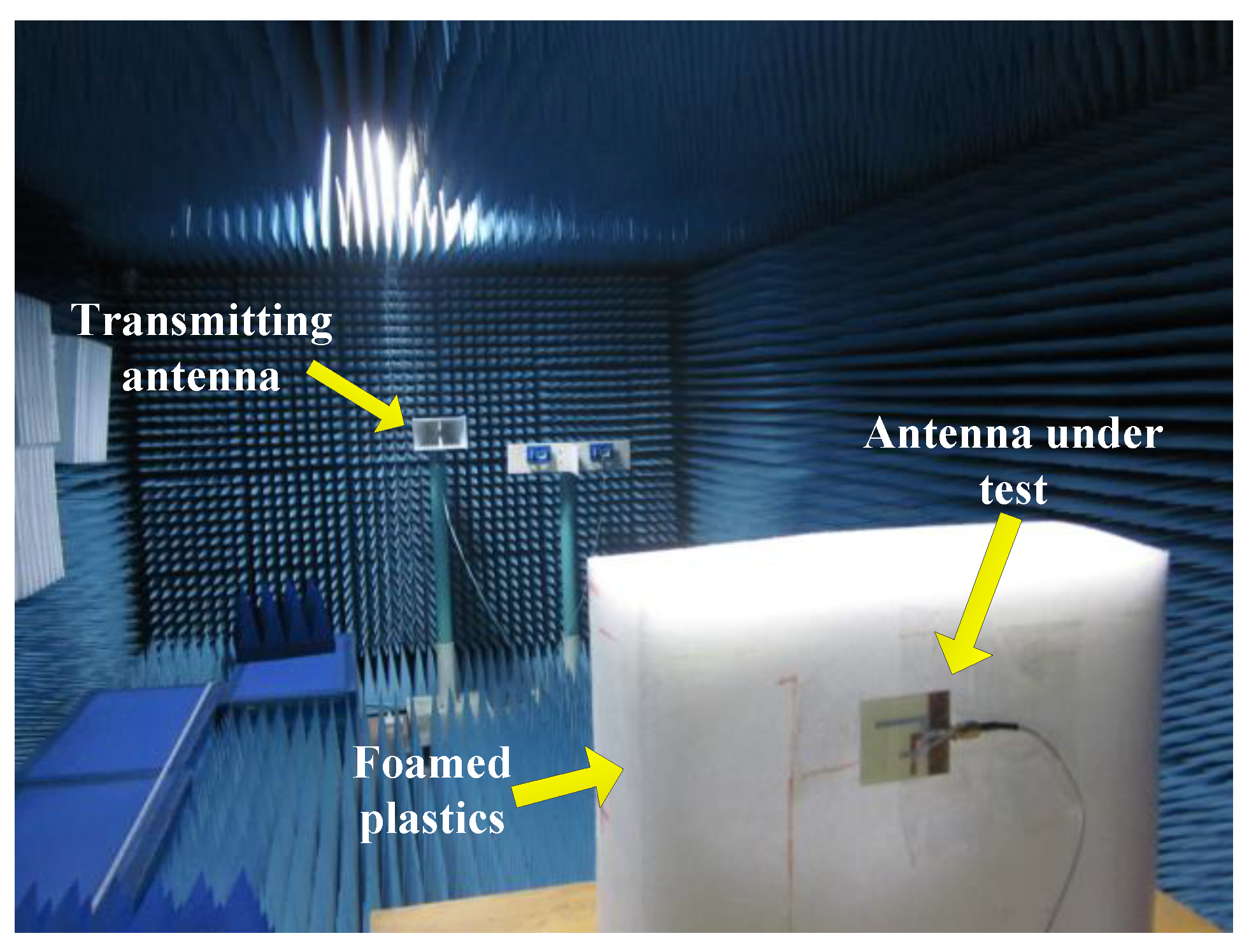
Figure 13.
Calculated and experimental S11 of the proposed NTTPA.

Figure 14.
Calculated and experimental Gain of the proposed NTTPA.
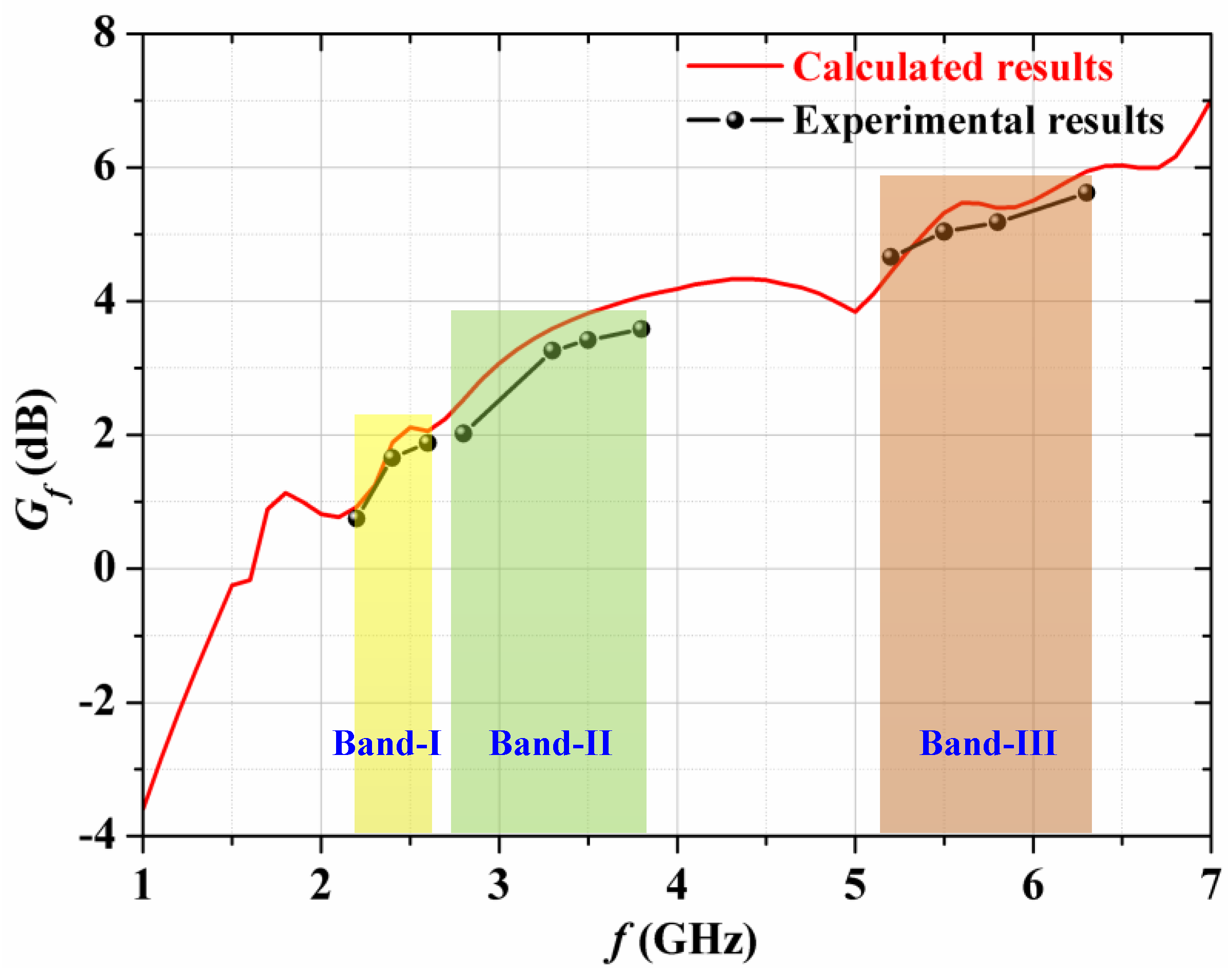
Figure 15.
Simulated and measured radiation patterns in x-o-z-plane and y-o-z-plane at: (a) 2.4 GHz, (b) 3.5 GHz, (c) 5.2 GHz, (d) 5.8 GHz.
Figure 15.
Simulated and measured radiation patterns in x-o-z-plane and y-o-z-plane at: (a) 2.4 GHz, (b) 3.5 GHz, (c) 5.2 GHz, (d) 5.8 GHz.

Figure 16.
Radiation efficiency of the proposed antenna.

Figure 17.
Front-to-back ratio of the proposed antenna.


Table 1.
Comparison of proposed NTTPA with previous antennas.
| Ref. | Antenna Reponse | Dimensions (λ0 × λ0) | Working Bands (GHz) | Radiation Effciency (%) | Gain (dBi) |
|---|---|---|---|---|---|
| [3] | Triple-band | 0.25λ0 × 0.53λ0 | 2.38–2.53 GHz 3.08–3.80 GHz 5.00–6.90 GHz | 88% 85% 75% | 1.1–1.5 dBi 4.6–5.6 dBi 2.0–3.6 dBi |
| [8] | Triple-band | 0.17λ0 × 0.32λ0 | 2.10–2.49 GHz 3.22–4.30 GHz 4.89–6.12 GHz | 72% 69% 80% | 2.7–3.2 dBi 3.1–3.5 dBi 2.8–3.3 dBi |
| [11] | Triple-band | 0.23λ0 × 0.27λ0 | 2.29–2.88 GHz 3.26–3.88 GHz 4.17–6.07 GHz | 85% 84% 83% | 3.8–4.4 dBi 4.0–4.7 dBi 1.9–3.5 dBi |
| [15] | Triple-band | 0.21λ0 × 0.25λ0 | 2.33–2.55 GHz 3.00–3.88 GHz 5.15–5.90 GHz | 62% 70% 79% | 1.1–1.4 dBi 2.4–3.5 dBi 2.5–3.3 dBi |
| [26] | Triple-band | 0.2λ0 × 0.25λ0 | 2.50–2.71 GHz 3.37–3.63 GHz 5.20–5.85 GHz | 98% 96% 94% | 1.3–2.5 dBi 1.4–2.4 dBi 1.3–2.6 dBi |
| [27] | Triple-band | 0.33λ0 × 0.37λ0 | 2.47–2.65 GHz 3.27–3.63 GHz 5.20–5.83 GHz | / / / | 1.8–2.4 dBi 1.8–2.4 dBi 1.7–2.4 dBi |
| Pre. | Triple-band | 0.33λ0 × 0.29λ0 | 2.20–2.63 GHz 2.73–3.80 GHz 5.13–6.30 GHz | 80% 85% 90% | 0.9–2.0 dBi 2.0–3.8 dBi 4.8–5.7 dBi |
Table 2.
Dimensions of the proposed antenna (all values are in mm).
| Parameter | Value | Parameter | Value | Parameter | Value |
|---|---|---|---|---|---|
| L0 | 45 | L1 | 12 | L5 | 26 |
| W0 | 40 | L2 | 6.5 | L6 | 11 |
| W | 3 | L3 | 6.5 | L7 | 6 |
| h | 1.6 | L4 | 16 | L8 | 20.5 |
Disclaimer/Publisher’s Note: The statements, opinions and data contained in all publications are solely those of the individual author(s) and contributor(s) and not of MDPI and/or the editor(s). MDPI and/or the editor(s) disclaim responsibility for any injury to people or property resulting from any ideas, methods, instructions or products referred to in the content. |
© 2023 by the authors. Licensee MDPI, Basel, Switzerland. This article is an open access article distributed under the terms and conditions of the Creative Commons Attribution (CC BY) license (https://creativecommons.org/licenses/by/4.0/).
Share and Cite
MDPI and ACS Style
Li, Q.; Fang, J.; Ding, J.; Cao, W.; Sun, J.; Guo, C.; Liu, T. A Novel Tuning Fork-Shaped Tri-Band Planar Antenna for Wireless Applications. Electronics 2023, 12, 1081. https://doi.org/10.3390/electronics12051081
AMA Style
Li Q, Fang J, Ding J, Cao W, Sun J, Guo C, Liu T. A Novel Tuning Fork-Shaped Tri-Band Planar Antenna for Wireless Applications. Electronics. 2023; 12(5):1081. https://doi.org/10.3390/electronics12051081
Chicago/Turabian StyleLi, Qiwei, Jinyong Fang, Jun Ding, Wen Cao, Jing Sun, Chenjiang Guo, and Tao Liu. 2023. "A Novel Tuning Fork-Shaped Tri-Band Planar Antenna for Wireless Applications" Electronics 12, no. 5: 1081. https://doi.org/10.3390/electronics12051081
Note that from the first issue of 2016, this journal uses article numbers instead of page numbers. See further details here.