

Short-Block-Length Low-Density Parity-Check Codes-Based Underwater Acoustic Spread-Spectrum Communication System

1
College of Joints Education Institution, Harbin Engineering University, Harbin 150001, China
2
Acoustic Science and Technology Laboratory, Harbin Engineering University, Harbin 150001, China
3
Key Laboratory of Marine Information Acquisition and Security, Harbin Engineering University, Ministry of Industry and Information Technology, Harbin 150001, China
4
College of Underwater Acoustic Engineering, Harbin Engineering University, Harbin 150001, China
5
Sanya Nanhai Innovation and Development Base of Harbin Engineering University, Sanya 572024, China
*
Author to whom correspondence should be addressed.
Electronics 2023, 12(18), 3884; https://doi.org/10.3390/electronics12183884
Submission received: 30 July 2023
/
Revised: 26 August 2023
/
Accepted: 12 September 2023
/
Published: 14 September 2023
(This article belongs to the Special Issue Applications and Challenges in Sonar Signal Processing)
Abstract
:Low-density parity-check (LDPC) codes are commonly used in communication systems to improve the system performance, but LDPC codes takes too long for decoding, making communication inefficient and unsuitable for short-frame data transmission methods. In underwater acoustic channels, spread-spectrum communication becomes an effective way to realize long-distance communication. This paper combines short-block LDPC codes with a direct sequence spread spectrum and soft spread spectrum in underwater acoustic communication, addressing the problem of the inapplicability of conventional LDPC codes. The applicability of the proposed method in this paper is verified through simulation tests and pool experiments. The results indicate that the proposed communication system achieves lower bit error rates compared to the classical coding methods used in underwater acoustic spread-spectrum communication systems under the same channel conditions.
1. Introduction
Underwater acoustic channels are complex and variable [1,2,3], and spread-spectrum communication techniques [4,5,6] are often used for robust acoustic communication. Considering the low-latency requirements of the communication system and the frame data volume of underwater acoustic spread-spectrum systems, short-block-length code is generally preferable in terms of its decoding latency and short-frame-data transmission.
MN Danish et al. constructed a quasi-cyclic LDPC (QC-LDPC) code based on Euclidean geometry and cyclic decomposition, which has a shorter girth, and, by comparing the BER performance of LDPC codes based on the randomized construction method with those constructed based on this method under different modulation modes, the (256,128) code based on the design of the method has a good performance [7]. Medova L R et al. proposed a new method for constructing LDPC codes based on the Orange Book of the Consultative Committee on Space Data Systems (CCSDS), “Short Block Length LDPC Codes for TC Synchronization and Channel Coding”, and the simulation experiments show that, compared with the LDPC codes in the experimental specification, the LDPC code constructed using this method can obtain about a 0.4 dB gain when the SER is 1 [8]. Ranganathan S V S et al. proposed a protograph-based Raptor-like (PBRL) low-density parity-check code design method that can obtain a better error frame rate at short-code-block lengths [9]. Abdu-Aguye U F et al. constructed short-block LDPC codes using an improved progressive edge-growth (PEG) algorithm; the LDPC codes constructed by this method have a shorter girth with a better approximate cycle extrinsic message degree than the existing PEG algorithm [10].
For spread-spectrum coding systems, in 2020, Rahman et al. [11] applied coding techniques to an ultrawideband spread-spectrum system and compared the performance of the spread-spectrum system using Turbo [12,13,14], low-density parity check (LDPC) [15,16] and Polar codes [17,18,19]. The direct sequence spread spectrum (DSSS) with a bit error rate (BER) of and a bandwidth of 1.2 GHz provided a spread-spectrum gain of about 21 dB. The spread-spectrum system using LDPC codes achieved a combined gain of over 30 dB, allowing for the successful retrieval of message signals with 1000× higher power interference. Peng et al. applied spread-spectrum coding techniques to UV scattering communication systems. Using the direct spread-spectrum method and LDPC codes with a code rate of 1/2 and a code length of 1024, the results showed that the coded system could achieve a BER of at dB, while the non-coded system achieved a BER of [20]. Wei X F et al. combined QC-LDPC code with spread-spectrum technology and high-order modulation technology, and the performance of an underwater acoustic spread-spectrum communication system is investigated: through simulation experiments, the underwater acoustic spread-spectrum system combining LDPC code has a better performance compared with the spread-spectrum system combining Turbo code, and can obtain a better BER performance under a low signal-to-noise ratio [21].
For spread-spectrum systems in underwater acoustics communications, in 2021, Yang G et al. addressed the signal distortion problem caused by the Doppler effect in mobile underwater acoustic communication scenarios by using different spread-spectrum codes with different frequency offsets as local reference signals, correlating the received signals one by one and searching for the maximum correlation value in the frequency domain and the code domain in order to complete the signal descaling and Doppler estimation. Simulations and experiments show that, compared to the average Doppler-compensated sliding correlation spread-spectrum method, this method has a better BER performance [5]. Sun D. et al. propose a Doppler tracking and compensation algorithm for direct spreading based on the fuzzy function method, which achieves high Doppler estimation accuracy at a 20 dB signal-to-noise ratio through high-precision delay estimation. Although the underwater acoustic spread-spectrum technique has strong multipath resistance by virtue of the good autocorrelation property of pseudorandom sequences, the multipath delay exceeding the spread-spectrum symbol length and the non-minimum phase underwater acoustic channel still bring serious inter-symbol interference (ISI) to the spread-spectrum signals, which affects the system reception signal-to-noise ratio (SNR) [22]. Sozer E. M. et al. used the RAKE receiver processing structure in the DSSS system to improve the SNR gain by utilizing the multipath energy [23]. Stojanovic M. et al. proposed a hypothesis-feedback equalization (HFE) algorithm in order to solve the effects of channel time-variation and ISI on the underwater acoustic spread spectrum, and the idea of judgment-feedback equalization can be applied in underwater acoustic spread-spectrum communication systems [24].
For the application of coding techniques in underwater acoustics communication, Xiaomei X et al. studied the performance of LDPC code in positive sound velocity gradient (PSVG), constant sound velocity gradient (CSVG) and negative sound velocity gradient (NVG) underwater acoustic channels, and the simulation shows that LDPC code has the best performance in the NSVG underwater channel, the second best performance in the ISVG underwater channel and the worst performance in the PSVG channel, and that there is a difference of about 4 dB compared to the former two [25]. As researchers recognize the changes in the harshness of the underwater channel environment, channel coding techniques based on adaptive code rate adjustment have been applied in underwater acoustic communication technology. Among them, the fountain code, which can generate arbitrary length characters, is a typical representative. It has the feature of coding without a code rate, which makes it have good application prospects in time-varying underwater acoustic channels. Therefore, in recent years, the main fountain codes LT code (Luby Transform Code), Raptor code, Strider code, etc., in underwater acoustic communication research have been put on the agenda, and there are preliminary experimental results that show that they have good error correction capabilities. Padala S K et al. applied spatially coupled low-density parity-check (SC-LDPC) code in an underwater acoustic OFDM communication system that has a high communication rate with low equalization complexity. Simulation experiments demonstrate that the performance of protograph-based SC-LDPC code is improved by about 1 dB at 1 BER compared to the general LDPC code with the same delay under the condition of a shallow water acoustic channel with 1000 m and a 10 KHz bandwidth [26].
In this paper, we study an underwater spread-spectrum system combining the Consultative Committee for Space Data Systems (CCSDS) 231.1-O-1 standard LDPC codes, and verify the system performance through simulations and water pool experimental analysis. The results show that the method proposed in this paper is suitable for underwater acoustic complex channels and the BER performance is improved compared to other existing coding methods. The LDPC coding and spread-spectrum methods used are listed in Table 1.
The remainder of this paper is organized as follows. Section 2 introduces the CCSDS codes and their encode/decode algorithms. Section 3 describes the DSSS, M-ary spread-spectrum, and cyclic-shift-keyed (CSK) spread-spectrum. Section 4 presents the simulated BER performance of the spread-spectrum coding system, and Section 5 analyzes the experimental results given by this spread-spectrum coding system. Section 6 discusses the results presented in this paper, before Section 7 concludes with a summary of this study.
2. LDPC Codes
The channel coding technique involves extending the original bit information by introducing parity bits and recovering the original information at the receiving end based on the correlation between the bit information. LDPC codes are linear block codes, the continuous binary sequence of symbols output from the source is called a message bit and the redundant binary sequence output after encoding according to certain rules is called a code word. In linear packet codes, the message bits are often divided into multiple groups of message packets of length k and sequentially encoded as code words of length n. A message code of length k can represent a total of types of messages. The message is mapped one-to-one with the codeword. Its code rate denotes the average number of message bits carried by a single code bit. Benefiting from the low-density feature of their check matrix, LDPC codes with iterative decoding based on belief propagation can obtain good error correction.
2.1. CCSDS Code
The check matrix of CCSDS codes consists of a submatrix of , where denote the code word length and the original bit length, respectively. Let denote the identity matrix, denote the zero matrix, denote the identity matrix cyclically shifted right by k bits and ⊕ denote the modulo-two addition of matrix elements at the corresponding positions. The check matrix can then be written as
From the check matrix of the CCSDS code, its generator matrix can be calculated by setting
where Q, P denote the submatrix of the first and last columns of the check matrix, respectively. Then, we have
where W can be calculated from
2.2. LDPC Decoding Algorithm
Based on the low-density characteristics of the LDPC check matrix, despite the belief that propagation-based iterative decoding algorithms is suboptimal, the result can still be obtained close to the optimal decoding criterion. The sum product algorithm (SPA) is a classical iterative decoding algorithm that accomplishes iterative decoding by passing messages between nodes. The log–likelihood ratio sum product algorithm (LLR-SPA) replaces probability domain calculations with likelihood domain calculations, reducing the algorithm complexity without changing the decoding performance.
In addition to matrix representation, LDPC codes can also be represented by Tanner graphs, which can be used to better illustrate the decoding algorithm. Tanner graphs are bipartite graphs, where nodes on the graph are classified into two categories: variable nodes (VNs) and check nodes (CNs), and lines connecting the two categories of nodes are called edges. Their equivalent Tanner graph can be obtained based on the check matrix H. According to this rule, the VN can correspond to the coded bits in the check equation, while the CN corresponds to the set of check equations. Tanner graphs are often used to describe sum–product decoding algorithms. An example of a Tanner graph is given in Figure 1. Let the jth variable node (VN) be and the ith check node (CN) be . In the check matrix, element indicates the existence of an edge between and on the Tanner graph. The specific LLR-SPA algorithm is as follows.
Step 1. Initialize the variable nodes according to Equation (7), where denotes the result of the channel message after initialization, denotes the actual value received by the channel and denotes the estimated value of the code word. According to the Tanner diagram, for , let :
Step 2. The CN is updated to calculate the extrinsic information passed according to Equation (8), where denotes the extrinsic information passed from to , denotes the set of nodes connected to and denotes any variable node connected to except :
Step 3. The VN is updated and the extrinsic information passed is calculated according to Equation (9), where denotes the extrinsic information passed from to , denotes the set of nodes connected to and denotes any check node connected to except .
Step 4. Sum the LLR according to
Step 5. Termination criterion: for , judge the code bits according to Equation (11). If the check condition is satisfied, terminate the decoding. Otherwise, the decoding has failed; return to step 2 and repeat the process until the decoding succeeds or the maximum number of iterations is reached.
3. Spread-Spectrum Technology
Spread-spectrum technology refers to the extension of narrowband data to a wider band and its transmission. The receiver obtains the spread-spectrum gain and recovers the data through correlated de-spreading. During this process, as the noise in the channel only experiences one spread spectrum, the energy is extended to a wider band. Thus, the in-band noise energy is reduced and the signal-to-noise ratio of the received signal is enhanced. With a better autocorrelation performance of the spread-spectrum sequence, any multipath energy beyond the duration of a code slice can be treated as noise. As the spread-spectrum symbol duration generally exceeds the multipath delay of the shallow water channel, ISI does not affect too many subsequent symbols, so the spread-spectrum technology itself has a strong anti-multipath performance.
3.1. Direct-Sequence Spread-Spectrum
The communication principles of the direct spread-spectrum system are shown in Figure 2. The transmitter spreads the signal to a wider frequency band, which is transmitted by carrier modulation and the channel, and the receiver performs the de-spreading of the received signal, restoring the broadband signal to a narrowband. The de-spread signal is then demodulated by the local carrier to restore the original information.
3.2. M-ary Spread-Spectrum
The M-ary spread-spectrum communication system improves band utilization compared with a direct spread communication system. The theoretical communication rate is times that of direct spreading using a random sequence of the same order, and each spreading symbol can carry bits of information, where ⌊ ⌋ denotes rounding down. The M-ary spread-spectrum exploits both the good autocorrelation properties and the quasi-positive cross-correlation properties of pseudorandom codes, using different spread-spectrum sequences for different spread-spectrum symbols to characterize this information. M-ary spread-spectrum communication is illustrated in Figure 3.
At the transmitter side, the data are divided into multiple groups of k bits through a serial-to-parallel conversion, which, for M-ary spreading, has . Each k bits of data constitute a spreading symbol, which is mapped to a spreading code according to certain rules. The k bits of data contain a total of binary sequences, which also correspond to spreading codes. The binary sequence is first converted to the corresponding decimal number , and then is selected as the spreading code from the mutually quasi-orthogonal M-ary spreading codes according to certain rules. We express as
denotes a pulse-forming function. The orthogonal M-ary spread-spectrum receiver consists of M correlators, which makes the hardware complexity of the receiver relatively high. To overcome this problem, the CSK spread-spectrum method is used to exploit the cyclic correlation property of pseudo-random codes, which are used to achieve spread-spectrum communication by splitting the source information into a few bits of spread-spectrum symbols that are then mapped into spread-spectrum codes. M-ary spread-spectrum communication achieves the mapping of symbols to spreading codes using pseudo-random codes with different sequences of the same length, such as Gold codes, where each symbol corresponds to a spreading code of that length. In contrast, CSK maps symbols to spreading codes using different cyclic shifts of the same spreading code. CSK spreading reduces the hardware complexity while maintaining transmission efficiency, but introduces new problems.
Figure 4a shows the results of cross-correlation between M-ary sequences of different principal polynomials of order seven, with a poor cross-correlation performance between spreading codes. Figure 4b plots the cross-correlation characteristics of a cyclic shift sequence of an M-sequence of order seven, spaced by 15 code pieces and carrying three bits of eight ary per symbol. In addition to the autocorrelation peak, there are several correlation peaks with similar energies. This indicates that if the signal is subject to severe multipath effects in the transmission process of the channel, such as the cross-correlation peak of spreading code 1 and cyclic code 2, which is close to the energy of the autocorrelation peak, the energy of the correlation peak is likely to exceed the energy of the autocorrelation peak under the influence of the superimposed multipath. This will result in a decoding error. The multipath component in this case cannot be regarded as noise and requires channel equalization, which leads to an increase in hardware complexity.
4. Simulations and Results
4.1. Overview of Spread-Spectrum Coding Systems
The communication schematic of a spread-spectrum coding system is shown in Figure 5, where bits of information are first coded by the channel and redundant check bits are added to obtain a code word for transmission. The length of the information bit before coding is given as k, the length of the code word after coding is given as n and the code rate is given as , indicating the amount of information carried by each channel bit. To reduce the effects of ISI, the baseband signal is waveformed. The baseband signal is then spread and carrier-modulated to be transmitted via the transducer to the underwater acoustic channel. After the receiver has received the acoustic signal, the signal is demodulated by the local carrier, filtered by low-pass filtering to remove out-of-band noise and then recovered by matched filtering and de-spreading.
The input to the decoder varies according to the spreading method used. For the direct spread system, the information is fed into the decoder without judgment, which allows the decoding performance of the soft judgment decoder to be fully utilized. For the M-ary spread-spectrum system, the judgment rule of detecting the maximum energy of the correlated peaks means that the information obtained after decoding is in the form of symbols, and is sent to the decoder as a 0.1 bit stream. This loses some of the channel information. Overall, the spread-spectrum coding system using the soft spread-spectrum combined with LDPC codes obtains a limited coding gain, and is inferior to the direct spread coding system.
4.2. Simulation Analysis
4.2.1. Channel Description
In this paper, we use Bellhop to simulate a channel that is as close as possible to the experimental conditions of the pool and bring it into the simulation experiments with the condition parameters of this channel (Figure 6):
Here, the depth of the simulated water body is set to 10 m, and the sound velocity profile is a negative gradient sound velocity environment, in which the depth of 0 m results in the speed of sound at the surface of the water being 1510 m/s, and the depth of 10 m results in the speed of sound at the bottom of the water being 1500 m/s. It is assumed that the surface of the water is a flat water surface with no undulation, the upper part of it is a vacuum environment, the bottom of it is assumed to be the liquid seabed and the sound velocity is 1650 m/s.
4.2.2. Simulation of Direct Spread-Spectrum Coding Systems
The simulation results for the direct spreading coding system based on a Gaussian channel and multipath channels are shown in Figure 7 and Figure 8. The sampling frequency kHz, the carrier frequency kHz, the bandwidth is 2 kHz, the spreading code is a 5th-order m-sequence and the spreading gain is 31. The modulation method is binary phase-shift keying (BPSK), the encoding code is CCSDS code, the decoding algorithm is LLR-SPA and the maximum number of iterations is 100. The simulations compare the performance of the direct spreading non-coding system with that of the direct spreading coding system. The direct spreading sequence system has the best performance under Gaussian channels and the performance decreases under multipath channels. With a BER of , a coding gain of about 7.2 dB can be obtained using CCSDS(512,256) codes. The simulation results also compare the performance of the spread-spectrum coding system using CCSDS codes with that of (2,1,7) convolutional codes, Bose–Chaudhuri–Hocquenghem (BCH) codes and Turbo codes. Under 1 BER conditions, the code length is the same as 256 and the code rate is 1/2 for both Turbo and LDPC codes. Compared to Turbo codes, the direct spreading sequence system with CCSDS codes has a gain of about 0.4 dB.
4.2.3. M-ary Spread-Spectrum Coding System Simulation
The simulation results for the M-ary spread-spectrum coding system under a Gaussian channel and multipath channels are shown in Figure 9 and Figure 10, where . Using a 5th-order Gold sequence as the spread-spectrum code, with a bandwidth of kHz, carrier frequency kHz, and sampling frequency kHz, the M-ary spread-spectrum system with CCSDS(512, 256) codes achieves a BER of with a minimum SNR of dB; the minimum SNR required for the uncoded system to achieve BER is dB. Thus, the coding gain is approximately 6.94 dB. Under 1 BER conditions, the code length is the same as 256 and the code rate is 1/2 for both Turbo and LDPC codes. Compared to Turbo codes, the M-ary spread-spectrum system with CCSDS codes has a gain of about 0.3 dB.
4.2.4. CSK Spread-Spectrum Coding System Simulation
The simulation results for the CSK spread-spectrum coding system under a Gaussian channel and multipath channels are shown in Figure 11 and Figure 12. In these simulations, , so 16 different spreading codes with a 5th-order M-sequence and 2-bit cyclic shift are used. The bandwidth kHz, carrier frequency kHz and sampling frequency kHz.
The simulation results are consistent with the theoretical analysis in that the direct spread coding system has the best coding gain while the soft spread coding system has limited coding gain. Spreading coding systems using short LDPC codes (CCSDS codes) achieve higher coding gains than spreading coding systems using other channel coding algorithms such as Turbo codes and convolutional codes. Under 1 BER conditions, the code length is the same as 256 and the code rate is 1/2 for both Turbo and LDPC codes. Compared to Turbo codes, the CSK spread-spectrum system with CCSDS codes has a gain of about 0.3 dB.
5. Water Pool Experiment
5.1. Experimental Conditions and Parameter Settings
Pool experiments were conducted to verify the feasibility of the spread-spectrum coding system. The pool measures 45 m × 6 m × 5 m, the pool bottom is deep sand and the pool wall has an anechoic tip split. Figure 13 shows a schematic diagram of the pool experiments, where the low-frequency transducer and the receiving hydrophone are nondirectional; the receiving hydrophone is a BK8105 hydrophone with a receiving sensitivity of dB. Figure 14 and Figure 15 show the placement of the transducer during the pool experiment and the overall experimental scene, respectively. Table 2 lists the parameters of the coded spread-spectrum system.
The channel response was first tested. Figure 16 shows the signal response curve with normalized amplitude.
5.2. Analysis of Experimental Results
5.2.1. Direct Spread-Spectrum Coding System
The BER performance of the DSSS communication system under different coding methods is shown in Figure 17. Analysis of Figure 17 indicates that the LDPC coding/decoding method using CCSDS codes can achieve a better coding gain than other channel coding algorithms, such as Turbo code, convolutional code and BCH code. The performance of (2, 1, 7) convolutional codes is related to the quantization accuracy, which is 4-bit quantization. The performance of Turbo codes is similar to that of LDPC codes at a lower SNR, and as the SNR increases, the method proposed in this paper has the best performance when the BER is 1 × 10⁻⁴, where it has a BER performance improvement of 0.3 dB compared to Turbo codes.
5.2.2. M-ary Spread-Spectrum Coding System
The experimental results of the M-ary spread-spectrum system are shown in Figure 18. The M-ary spread-spectrum error comes from the maximum correlation peak detection error. This causes the M-ary spread-spectrum to lose part of the channel information, and can make all bits in a symbol erroneous. Together, these issues affect the performance of the M-ary spread-spectrum coding system.
5.2.3. CSK Spread-Spectrum Coding System
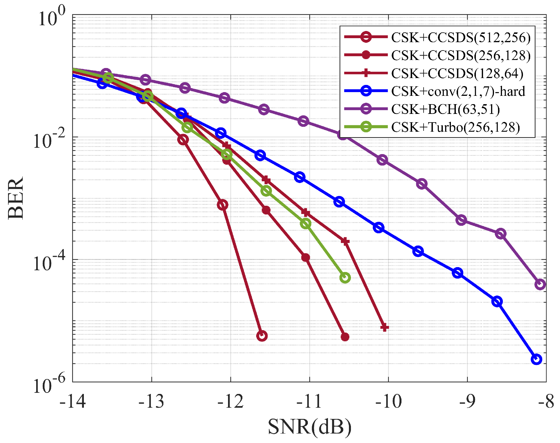
The experimental results for the CSK spread-spectrum communication system under different coding methods are shown in Figure 19. Analyzing the results of pool experiments, for channel coding methods with similar code lengths and consistent communication rates, spread-spectrum communication systems incorporating CCSDS codes have certain performance advantages over spread-spectrum communication systems incorporating other coding methods.
6. Discussion
6.1. Significance of the Proposed Method
The spread-spectrum coding system proposed in this paper has a better BER performance than the underwater acoustic spread-spectrum communication system using classical coding methods, and the technique enables robust transmission of short-frame data. The performance of the spread-spectrum coding system combined with CCSDS short-block LDPC codes has been verified through simulations and pool experiments to outperform the spread-spectrum system combined with the classical coding method.
The DSSS + LDPC spread-spectrum coding system has the best BER performance and is suitable for applications with limited transmission energies and high BER requirements, such as satellite communications. The soft spread-spectrum + LDPC spread-spectrum coding system offers improved band utilization, but is limited by the spread-spectrum method, which reduces its BER performance. This approach is more suitable for communication scenarios with limited bandwidth resources.
6.2. Limitations of the Proposed Method
The soft spreading coding system combined with LDPC codes proposed in this paper loses channel information during the process of mapping the spreading sequence to symbols. This degrades its BER performance. To achieve an improved BER performance, the main correlation peak and the secondary correlation peak symbols of the M-ary correlator decoding could be combined and the input to the decoder could be adjusted to compensate for the partial loss of channel information. In addition, the performance of the method can be further verified in extreme environments through sea trial experiments.
7. Conclusions
This paper has proposed a short-block LDPC coding system for underwater acoustic spread-spectrum communication that is highly adaptable to the short-frame data transmission process. Simulation experiments and pool experiments have verified the effectiveness and practicality of the proposed method in this paper. Simulation analysis shows that the proposed direct spread coding system can achieve a coding gain of up to 7.2 dB in BER compared with the direct spread non-coding system. The proposed M-ary spread coding system and CSK spread coding system can achieve coding gains of up to 6.94 dB and 5.64 dB, respectively, compared with their corresponding spread non-coding systems. Pool experiment results also show that the proposed method has a better BER performance compared to conventional coding methods in underwater acoustic communication systems. This method has good application prospects in the field of underwater acoustic communication.
Author Contributions
Conceptualization, Z.Z.; methodology, Z.Z. and Z.S.; software, Z.Z.; validation, Z.Z. and Z.S.; formal analysis, Z.S.; investigation, Z.Z.; resources, Z.Z.; data curation, Z.Z.; writing—original draft preparation, Z.Z. and Z.S.; writing—review and editing, Z.Z. and Z.S.; visualization, Z.S.; supervision, Z.S.; project administration, Z.Z.; funding acquisition, Z.S. All authors have read and agreed to the published version of the manuscript.
Funding
The work was supported in part by the Open Foundation of the Key Laboratory of Underwater Information and Control of Grant no. J2322048.
Data Availability Statement
The data presented in this paper are available after contacting the corresponding author.
Acknowledgments
The authors would like to thank the anonymous Reviewers for their careful reading and valuable comments.
Conflicts of Interest
The authors declare no conflict of interest.
References
- Khan, M.R.; Das, B.; Pati, B.B. Channel estimation strategies for underwater acoustic (UWA) communication: An overview. J. Frankl. Inst. 2020, 357, 7229–7265. [Google Scholar] [CrossRef]
- Zhang, Y.; Venkatesan, R.; Dobre, O.A.; Li, C. Efficient estimation and prediction for sparse time-varying underwater acoustic channels. IEEE J. Ocean. Eng. 2019, 45, 1112–1125. [Google Scholar] [CrossRef]
- Boluda-Ruiz, R.; Rico-Pinazo, P.; Castillo-Vázquez, B.; Zambrana, A.; Qaraqe, K. Impulse response modeling of underwater optical scattering channels for wireless communication. IEEE Photonics J. 2020, 12, 1–14. [Google Scholar] [CrossRef]
- Yang, G.; Zhou, F.; Lou, Y.; Qiao, G.; Ahmed, N.; He, Y. Double-differential coded M-ary direct sequence spread spectrum for mobile underwater acoustic communication system. Appl. Acoust. 2021, 183, 108303. [Google Scholar] [CrossRef]
- Yang, G.; Zhou, F.; Qiao, G.; Zhao, Y.; Liu, Y.; Lu, Y.; He, Y. Optimized Doppler Estimation and Symbol Synchronization for Mobile M-ary Spread Spectrum Underwater Acoustic Communication. J. Mar. Sci. Eng. 2021, 9, 1001. [Google Scholar] [CrossRef]
- Lyu, W.C.; Zhao, M.M.; Chen, X.; Yang, X.; Qiu, Y.; Hu, J. Experimental demonstration of an underwater wireless optical communication employing spread spectrum technology. Opt. Express 2020, 28, 10027–10038. [Google Scholar] [CrossRef] [PubMed]
- Danish, M.N.; Pasha, S.A.; Hashmi, A.J. Quasi-cyclic LDPC codes for short block-lengths. In Proceedings of the 2021 IEEE Aerospace Conference (50100), Big Sky, MT, USA, 6–13 March 2021; pp. 1–8. [Google Scholar]
- Medova, L.R.; Rybin, P.S.; Filatov, I.V. Short length LDPC code-candidate for satellite control channel. In Proceedings of the 2018 Engineering and Telecommunication (EnT-MIPT), Moscow, Russia, 15–16 November 2018; pp. 163–166. [Google Scholar]
- Ranganathan SV, S.; Divsalar, D.; Wesel, R.D. Quasi-cyclic protograph-based raptor-like LDPC codes for short block-lengths. IEEE Trans. Inf. Theory 2019, 65, 3758–3777. [Google Scholar] [CrossRef]
- Abdu-Aguye, U.F.; Ambroze, M.A.; Tomlinson, M. Improved minimum weight, girth, and ACE distributions in ensembles of short block length irregular LDPC codes constructed using PEG and cyclic PEG (CPEG) algorithms. In Proceedings of the 2016 9th International Symposium on Turbo Codes and Iterative Information Processing (ISTC), Brest, France, 5–9 September 2016; pp. 186–190. [Google Scholar]
- Rahman, M.R.; Bojja-Venkatakrishnan, S.; Alwan, E.A.; Volakis, J.L. Spread Spectrum Techniques with Channel Coding for Wideband Secured Communication Links. In Proceedings of the 2020 IEEE International Symposium on Antennas and Propagation and North American Radio Science Meeting, Montreal, QC, Canada, 5–10 July 2020; pp. 1783–1784. [Google Scholar]
- Qiu, M.; Wu, X.; i Amat, A.G.; Yuan, J. Analysis and design of partially information-and partially parity-coupled Turbo codes. IEEE Trans. Commun. 2021, 69, 2107–2122. [Google Scholar] [CrossRef]
- He, Y.; Zhang, J.; Jin, S.; Li, G.; Wen, C. Model-driven DNN decoder for Turbo codes: Design, simulation, and experimental results. IEEE Trans. Commun. 2020, 68, 6127–6140. [Google Scholar] [CrossRef]
- Spasov, D. Decoding of LTE Turbo Codes Initialized with the Two Recursive Convolutional Codes. In Proceedings of the 2020 43rd International Convention on Information, Communication and Electronic Technology (MIPRO), Opatija, Croatia, 28 September–2 October 2020; pp. 393–396. [Google Scholar]
- Mostari, L.; Taleb-Ahmed, A. High performance short-block binary regular LDPC codes. Alex. Eng. J. 2018, 57, 2633–2639. [Google Scholar] [CrossRef]
- Ranganathan, S.V.S.; Divsalar, D.; Wesel, R.D. Design of improved quasi-cyclic protograph-based Raptor-like LDPC codes for short block-lengths. In Proceedings of the 2017 IEEE International Symposium on Information Theory (ISIT), Aachen, Germany, 25–30 June 2017; pp. 1207–1211. [Google Scholar]
- Li, W.; Zhang, W.; Li, L.; Zhou, H.; Yu, N. Designing near-optimal steganographic codes in practice based on polar codes. IEEE Trans. Commun. 2020, 68, 3948–3962. [Google Scholar] [CrossRef]
- Geiselhart, M.; Elkelesh, A.; Ebada, M.; Liu, M. CRC-aided belief propagation list decoding of polar codes. In Proceedings of the 2020 IEEE International Symposium on Information Theory (ISIT), Shenzhen, China, 13–15 November 2020; pp. 395–400. [Google Scholar]
- Liao, Y.; Hashemi, S.A.; Cioffi, J.M.; Goldsmith, A. Construction of polar codes with reinforcement learning. IEEE Trans. Commun. 2021, 70, 185–198. [Google Scholar] [CrossRef]
- Peng, Y.; Zhou, D.; Yang, F. Performance Analysis of LDPC in Ultraviolet Communication System. In Proceedings of the 2020 IEEE International Conference on Artificial Intelligence and Computer Applications (ICAICA), Dalian, China, 27–29 June 2020; pp. 292–295. [Google Scholar]
- Wei, X.F.; Chen, J. Performance Simulation of Underwater Acoustic Spread Spectrum Communication Based on LDPC Code. J. Phys. Conf. Ser. 2021, 1873, 012018. [Google Scholar] [CrossRef]
- Sun, D.; Hong, X.; Cui, H.; Liu, L. A symbol-based passband Doppler tracking and compensation algorithm for underwater acoustic DSSS communications. J. Commun. Inf. Netw. 2020, 5, 168–176. [Google Scholar] [CrossRef]
- Sozer, E.M.; Proakis, J.G.; Stojanovic, R.; Liu, L. Direct sequence spread spectrum based modem for under water acoustic communication and channel measurements. In Proceedings of the Oceans’ 99, MTS/IEEE, Riding the Crest into the 21st Century, Conference and Exhibition (IEEE Cat. No. 99CH37008), Seattle, WA, USA, 13–16 September 1999; Volume 1, pp. 228–233. [Google Scholar]
- Stojanovic, M.; Freitag, L. Hypothesis-feedback equalization for direct-sequence spread-spectrum underwater communications. In Proceedings of the OCEANS 2000 MTS/IEEE Conference and Exhibition (Cat. No. 00CH37158), Providence, RI, USA, 11–14 September 2000; Volume 1, pp. 123–129. [Google Scholar]
- Xiaomei, X.; Yougan, C.; Lan, Z.; Liu, L. Comparison of the performance of LDPC codes over different underwater acoustic channels. In Proceedings of the 2010 IEEE 12th International Conference on Communication Technology, Nanjing, China, 11–14 November 2010; pp. 155–158. [Google Scholar]
- Padala, S.K.; D’Souza, J. Performance of spatially coupled LDPC codes over underwater acoustic communication channel. In Proceedings of the 2020 National Conference on Communications (NCC), Kharagpur, India, 21–23 February 2020; pp. 1–5. [Google Scholar]
Figure 1.
Tanner chart.

Figure 2.
Direct spread-spectrum system communication schematic.
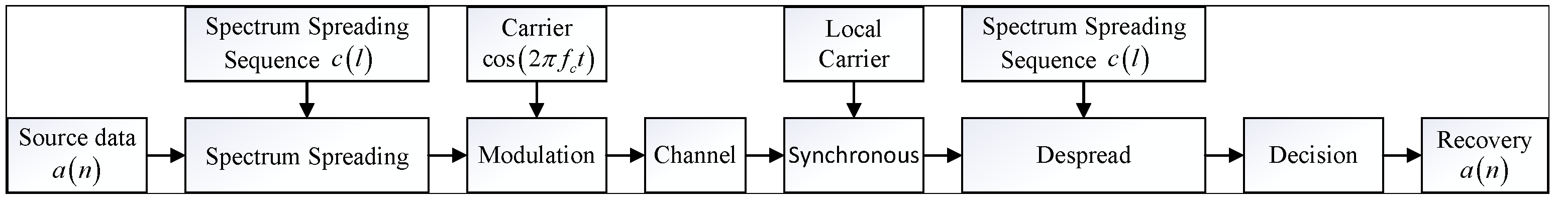
Figure 3.
M-ary spread-spectrum communication system schematic.
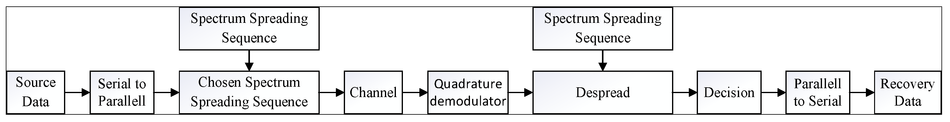
Figure 4.
Spread-spectrum sequence correlation characteristics. (a) Seventh-order M-series correlation properties; (b) Cyclic shift sequence correlation properties for seventh-order M-sequences.
Figure 4.
Spread-spectrum sequence correlation characteristics. (a) Seventh-order M-series correlation properties; (b) Cyclic shift sequence correlation properties for seventh-order M-sequences.
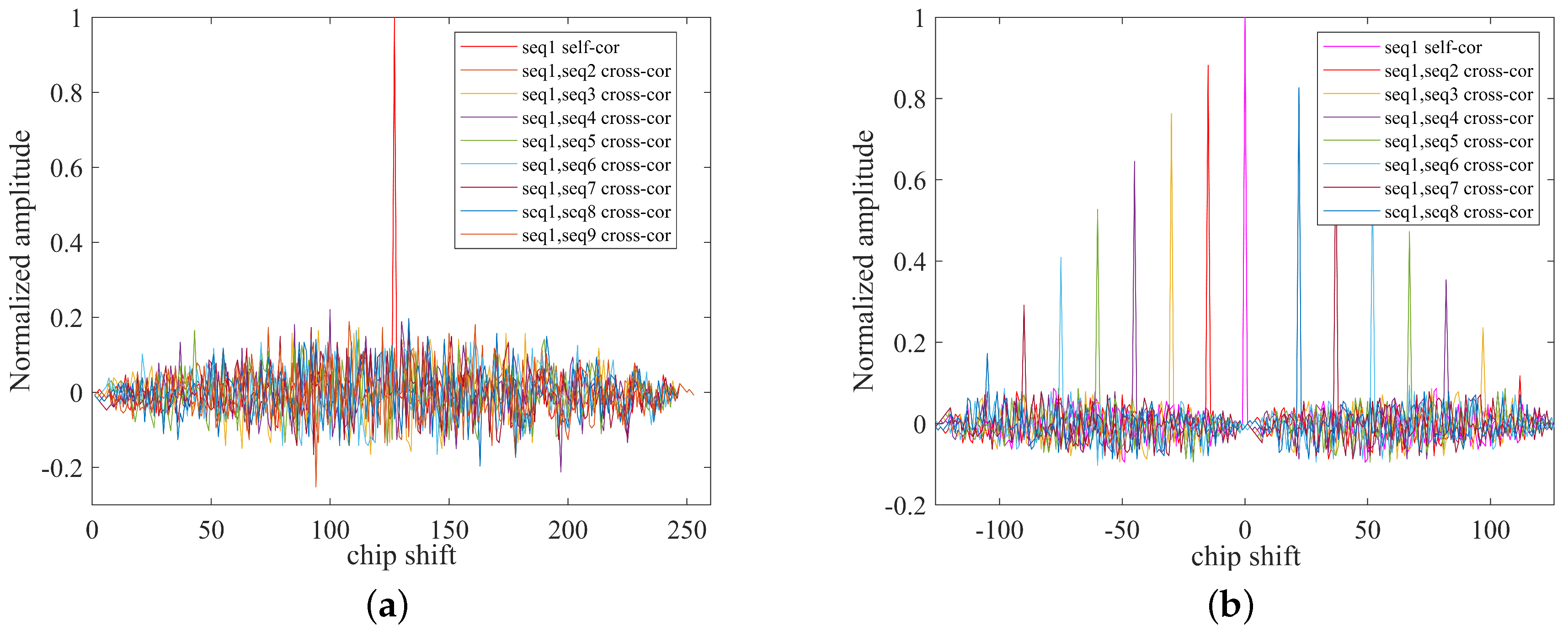
Figure 5.
Communication schematic for spread-spectrum coding systems.

Figure 6.
Channel impulse response of the simulation.
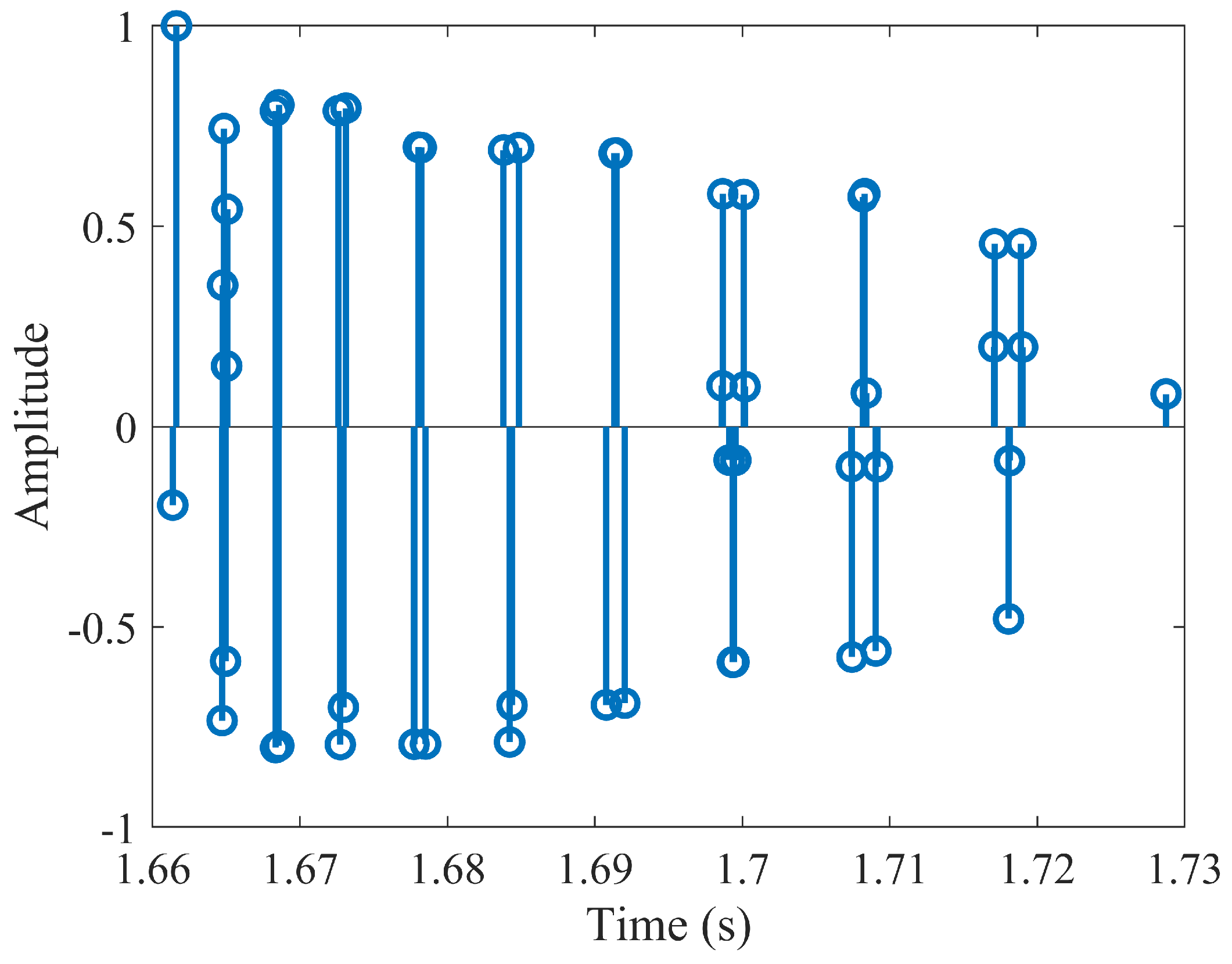
Figure 7.
BER performance of DSSS coding systems in Gaussian channel.
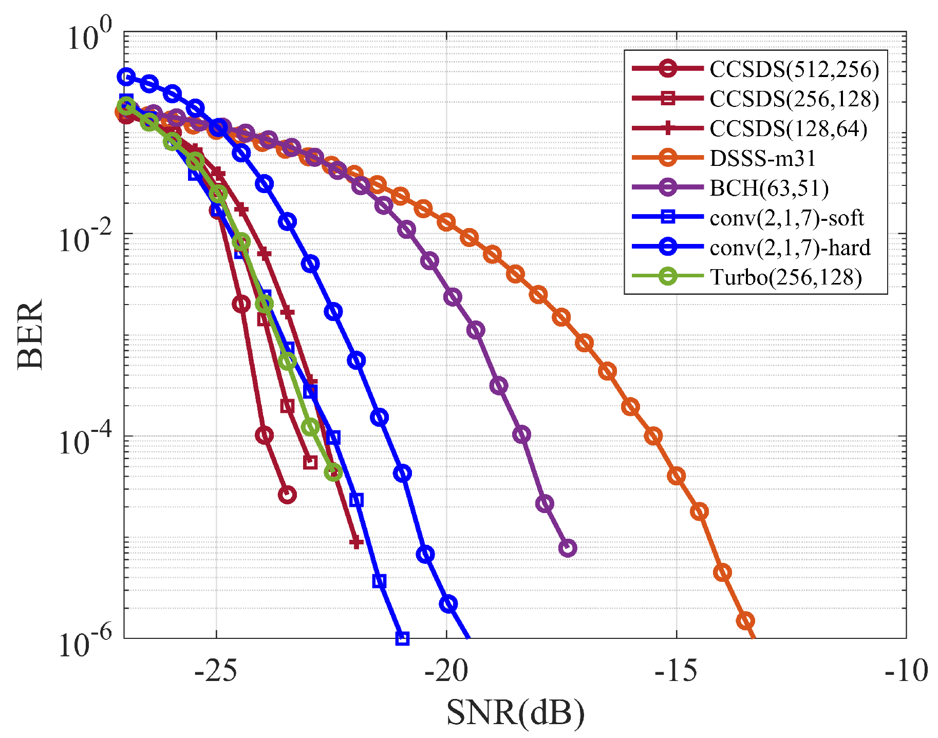
Figure 8.
BER performance of DSSS coding systems in multipath channel.
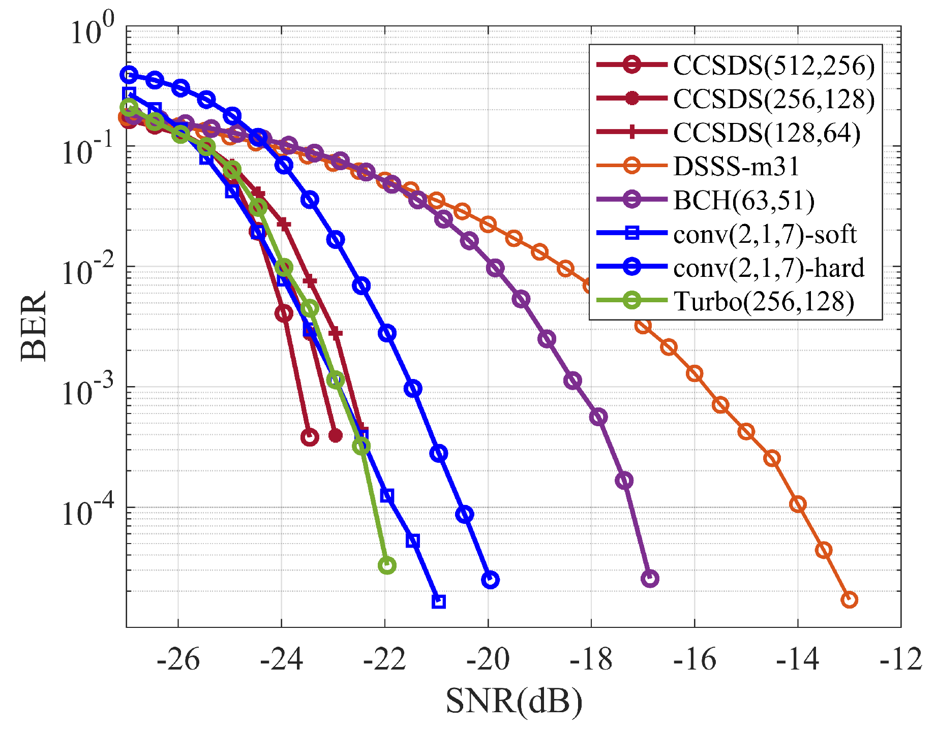
Figure 9.
BER performance of M-ary spread-spectrum coding systems in Gaussian channel.
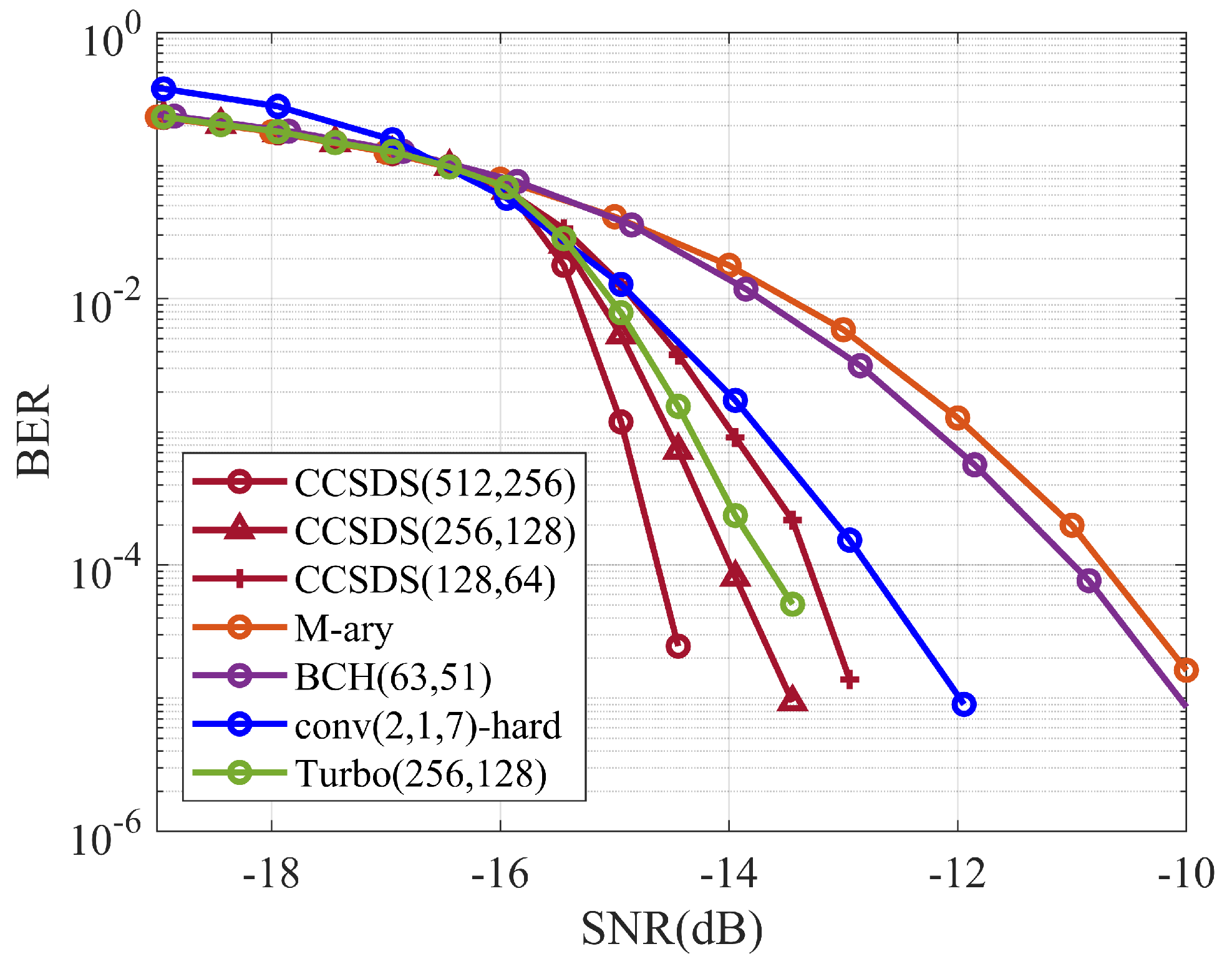
Figure 10.
BER performance of M-ary spread-spectrum coding systems in multipath channel.
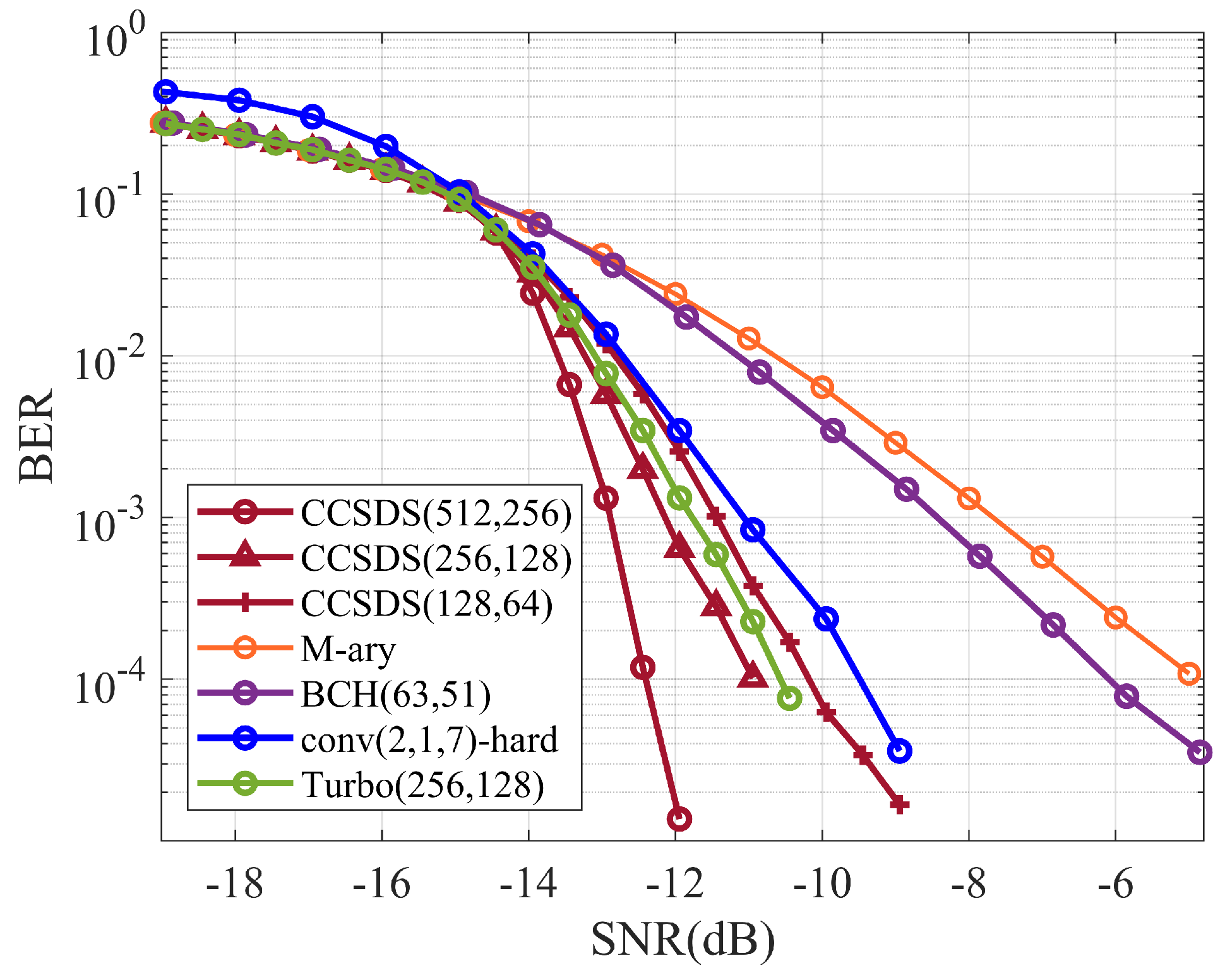
Figure 11.
BER performance of CSK spread-spectrum coding systems in Gaussian channel.

Figure 12.
BER performance of CSK spread-spectrum coding systems in multipath channel.
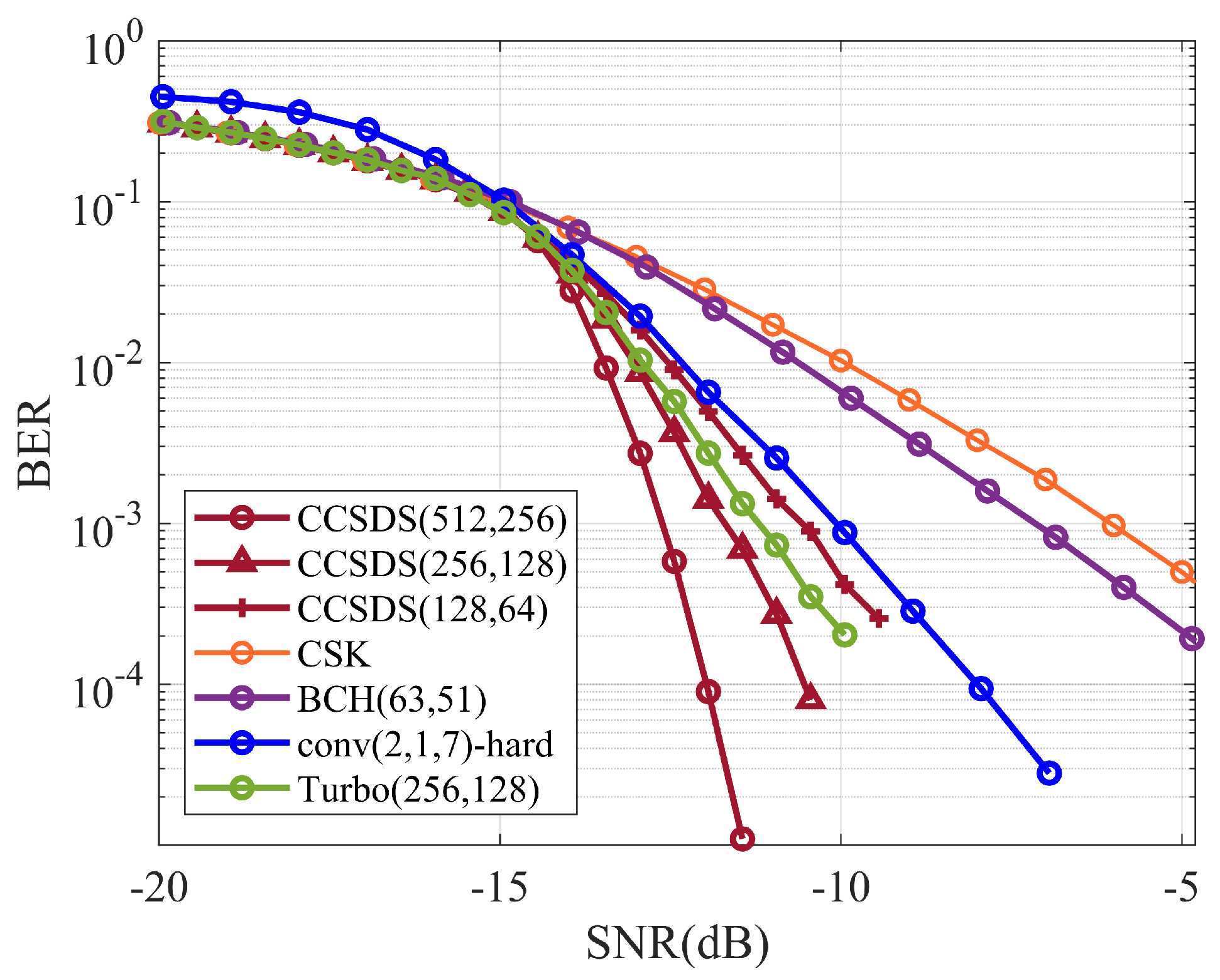
Figure 13.
Schematic diagram of pool experiments.

Figure 14.
Transducer placement scenario.
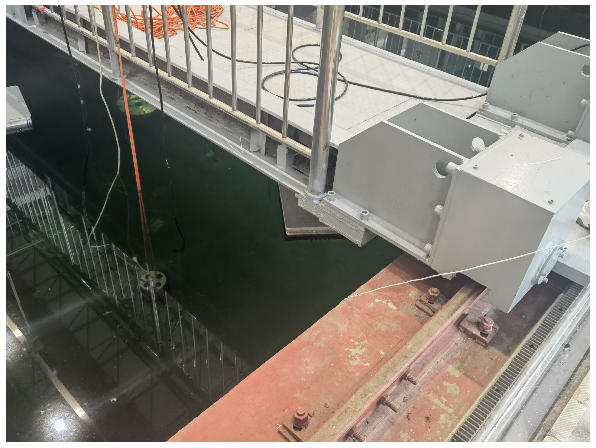
Figure 15.
Pool experiment scenario.

Figure 16.
Pool measurement channel response curve.

Figure 17.
BER of DSSS communication system under different coding methods.
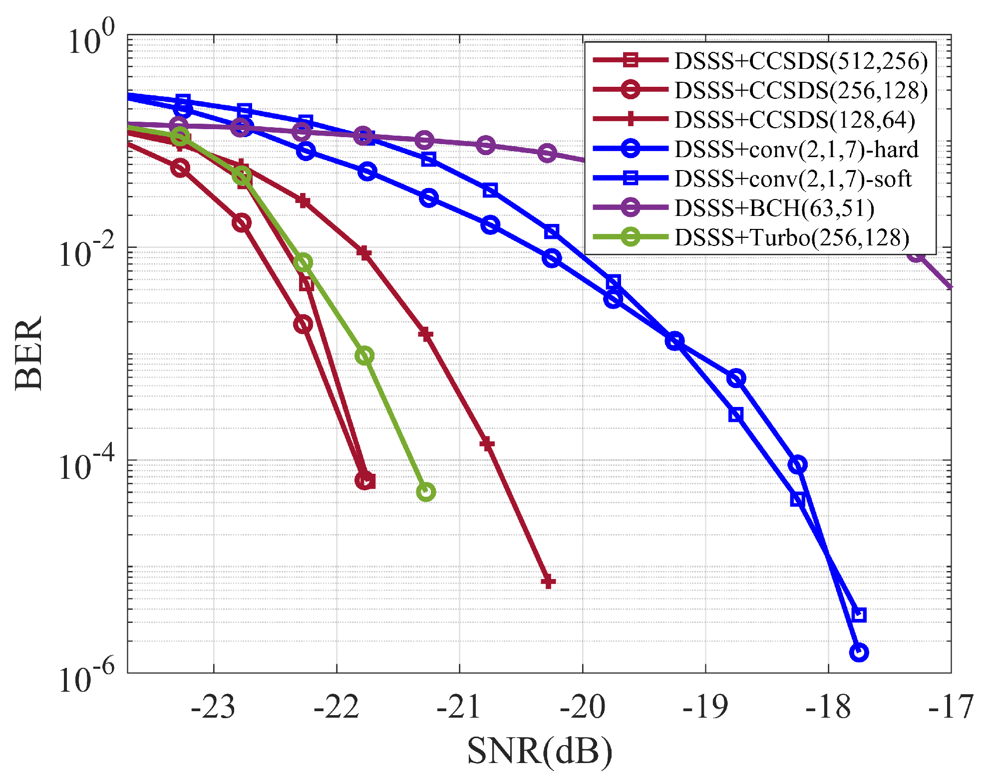
Figure 18.
BER of M-ary spread-spectrum communication system under different coding methods.

Figure 19.
BER of CSK spread-spectrum communication system under different coding methods.

Table 1.
Spread-spectrum coding system research content.
| Spectrum | Spreading Mode | Codes|Modulation |
|---|---|---|
| DSSS | CCSDS(512,256) | BPSK |
| CCSDS(256,128) | ||
| CCSDS(128,64) | ||
| M-ary SS | CCSDS(512,256) | BPSK |
| CCSDS(256,128) | ||
| CCSDS(128,64) | ||
| CSK SS | CCSDS(512,256) | BPSK |
| CCSDS(256,128) | ||
| CCSDS(128,64) |
Table 2.
Parameter settings for encoding spread-spectrum system.
| System bandwidth | 2 kHz |
| Carrier frequency | 2 kHz |
| Modulation | BPSK |
| Spread-spectrum system | DSSS/M-ary SS(16ary)/CSK SS(16ary) |
| Roll-off factor | 0.5 |
| Frame synchronization | LFM |
| Encoding | CCSDS(512,256)/(256,128)/(128,64) |
| Decoding | Normalized-MSA |
| Spreading sequence | 5-step M-sequence (DSSS) |
| 5-step Gold sequence (M-ary SS) | |
| 5-step M-sequence cyclic shift (CSK SS) | |
| Bit rate | 32.3 bps (DSSS) |
| 129.0 bps (M-ary) | |
| 129.0 bps (CSK) |
Disclaimer/Publisher’s Note: The statements, opinions and data contained in all publications are solely those of the individual author(s) and contributor(s) and not of MDPI and/or the editor(s). MDPI and/or the editor(s) disclaim responsibility for any injury to people or property resulting from any ideas, methods, instructions or products referred to in the content. |
© 2023 by the authors. Licensee MDPI, Basel, Switzerland. This article is an open access article distributed under the terms and conditions of the Creative Commons Attribution (CC BY) license (https://creativecommons.org/licenses/by/4.0/).
Share and Cite
MDPI and ACS Style
Zhao, Z.; Sun, Z. Short-Block-Length Low-Density Parity-Check Codes-Based Underwater Acoustic Spread-Spectrum Communication System. Electronics 2023, 12, 3884. https://doi.org/10.3390/electronics12183884
AMA Style
Zhao Z, Sun Z. Short-Block-Length Low-Density Parity-Check Codes-Based Underwater Acoustic Spread-Spectrum Communication System. Electronics. 2023; 12(18):3884. https://doi.org/10.3390/electronics12183884
Chicago/Turabian StyleZhao, Zichen, and Zongxin Sun. 2023. "Short-Block-Length Low-Density Parity-Check Codes-Based Underwater Acoustic Spread-Spectrum Communication System" Electronics 12, no. 18: 3884. https://doi.org/10.3390/electronics12183884
Note that from the first issue of 2016, this journal uses article numbers instead of page numbers. See further details here.