Article

Development of Directional 14 MeV-Fusion Neutron Detector Using Liquid-Scintillator-Filled Capillaries

1
National Institute of Technology, Toyama College, 13 Hongo-machi, Toyama 939-8630, Japan
2
National Institute of Technology, Gakujutsu-Sogo-Center 10F, 2-1-1 Hitotsubashi, Chiyoda-ku 101-0003, Japan
3
National Institutes for Quantum Science and Technology, 801-1 Mukoyama, Naka 311-0193, Japan
4
Graduate School of Frontier Sciences, The University of Tokyo, 5-1-5 Kashiwanoha, Kashiwa 277-0882, Japan
5
Graduate School of Engineering, Nagoya University, Furo-cho, Chikusa-ku, Nagoya 464-8601, Japan
6
Department of Physics, Mahasarakham University, Maha Sarakham 44150, Thailand
7
Fusion Science Program, The Graduate University for Advanced Studies, SOKENDAI, 322-6 Oroshi-cho, Toki 509-5202, Japan
8
National Institute for Fusion Science, 322-6 Oroshi-cho, Toki 509-5202, Japan
9
Quantum Science and Energy Engineering, Graduate School of Engineering, Tohoku University, Sendai 980-8579, Japan
10
Division of Sustainable Energy and Environmental Engineering, Graduate School of Engineering, Osaka University, Yamadaoka 2-1, Suita 565-0871, Japan
*
Author to whom correspondence should be addressed.
Present address: Materials Science and Engineering, Tokyo Institute of Technology, 2-12-1, Ookayama, Meguro-ku 152-8550, Japan.
Electronics 2023, 12(15), 3219; https://doi.org/10.3390/electronics12153219
Submission received: 29 May 2023 / Revised: 4 July 2023 / Accepted: 13 July 2023 / Published: 25 July 2023

Abstract

:
Triton burnup studies have been performed in fusion experimental devices to evaluate the confinement performance of 3.5 MeV alpha particles. For this purpose, the generation rate of deuterium-tritium (D-T)-born 14 MeV neutrons has been measured using a scintillating fiber detector. The directionality of this detector provides excellent selectivity for 14 MeV neutrons; however, the lack of a pulse–shape discrimination (PSD) capability limits high-energy gamma-ray reduction. In this study, we developed a new 14 MeV neutron detector with directionality that can discriminate neutrons and gamma rays based on the PSD technique by filling capillaries with a liquid scintillator. The performance of this detector was evaluated at the FNL (Tohoku University, Japan) and OKTAVIAN (Osaka University, Japan). The detector response was modeled using the particle and heavy ion transport code system (PHITS). The experimental and simulation results demonstrated that the detector has a directional response to fast neutrons and excellent PSD capability.

1. Introduction

The confinement of 3.5 MeV alpha particles produced by the deuterium-tritium (D-T) reaction is essential for commercializing fusion energy because they heat and sustain plasma through colliding with the plasma. Therefore, triton burnup studies have been performed [1,2,3,4,5,6,7], where the ratio of the D-T neutron generation rate to the D-D neutron generation rate in deuterium plasma has been used to evaluate the confinement performance of triton particles. Because the spatial and time scale of the motion of triton particles resembles those of alpha particles [8], the behavior of alpha particles can be estimated.
For this purpose, various types of D-T neutron detectors have been developed and operated in experimental fusion devices. For example, silicon diodes, which have a high-energy resolution, were used to measure D-T neutrons produced by 1 MeV tritons at TFTR [9,10,11]. They successfully measured the time evolution of 14 MeV neutrons. However, this detector is susceptible to radiation damage. In recent years, there have been advancements in the development of 14 MeV neutron detectors using silicon carbide or diamond crystals [12,13,14,15,16,17,18,19,20]. These detectors are gaining attention due to their reduced susceptibility to temperature changes, light, and radiation. However, they are expensive and have a limited counting efficiency due to their size constraints. Scintillating fiber (Sci. Fi.) detectors, which use plastic scintillators processed into a fiber form, have been used to conduct the time-resolved D-T neutron measurements at TFTR, LHD, JT-60U, and KSTAR [21,22,23,24,25,26,27,28,29,30,31]. This detector offers a high-speed response, radiation resistance, and directional sensitivity to 14 MeV neutrons. However, one drawback of this detector is that it does not have a pulse–shape discrimination (PSD) capability. Therefore, it uses pulse height discrimination to distinguish between signals from D-T neutrons and those from background gamma rays and D-D neutrons, which exploits the fact that the pulse height of the scintillation light is proportional to the energy deposited by the excited particle. By setting an appropriate threshold for the pulse height value, low-energy gamma rays and D-T neutrons can be discriminated. However, the light output of organic scintillators, including Sci. Fi. detectors, for electrons has a greater per unit energy than that of ions. Therefore, 2–3 MeV neutrons, which collide with ions in the detector, are required to provide the same light output as a 1 MeV gamma ray. For instance, the pulse height of a 7.8 MeV gamma ray due to the neutron capture reaction of 56Fe in stainless steel is compatible with that of 14 MeV (D-T) neutrons. Therefore, the contamination of signals by high-energy gamma rays is inevitable when using pulse-height discrimination alone. Organic scintillators such as stilbene (solid) and EJ-301 (liquid) have also been used as a D-T neutron detector at LHD [22,23,24,25,26,27,28,29,30,31,32,33] and JT-60U [34,35]. They offer a high counting efficiency and possess a PSD capability, enabling the differentiation of pulses originating from interactions between neutrons and gamma rays. However, unlike Sci. Fi. detectors, stilbene is not directional to D-T neutrons due to the difficulty in fabricating a long shape. On the other hand, liquid scintillators provide shape flexibility through container adjustment. However, preventing the quenching caused by dissolved oxygen necessitates the creation of an oxygen-free environment using nitrogen gas, which presents challenges when it comes to sealing it within the container.
This study focused on neutron–gamma ray discrimination using the PSD method. Material, such as stilbenes and liquid scintillators, can discriminate between neutrons and gamma rays using the difference in the time constant of the pulse decay depending on the excited particle. Therefore, although their pulse height values are comparable, neutrons and gamma rays can be discriminated. By filling capillaries with a liquid scintillator, we developed a new concept of a 14 MeV neutron detector with both directionalities, like Sci. Fi. detectors, and neutron–gamma-ray-discrimination capability using the PSD technique to provide the precise experimental data needed to elucidate the physics of high-energy alpha particle confinement. The performance of the detector was demonstrated at FNL (Tohoku University, Japan) [36] and OKTAVIAN (Osaka University, Japan) [37]. In addition, the detector response was modeled using the particle and heavy ion transport code system [38]. The experimental and simulation results demonstrated that the detector has a directional response to fast neutrons and an outstanding PSD capability. We anticipate that this detector can be installed in an environment with a total neutron emission rate exceeding 1016 neutrons/s, which corresponds to a neutron flux of ~1010 cm−1 s−1 at the torus hall in LHD [39], where the Sci. Fi. detectors are installed.

2. Materials and Methods

2.1. Sci. Fi. Detector

Sci. Fi. detectors were developed in the 1990s to measure 14 MeV neutrons for fusion experimental devices, such as TFTR and JT-60U. As shown in Figure 1, a Sci. Fi. detector consists of a sensor head with several scintillating fibers embedded in the housing, which is connected to a photomultiplier tube (PMT). The commonly used scintillating fiber in Sci. Fi. detectors is BCF-10 (Saint Gobain) [22,23,26]. Its emission peak is 432 nm, its decay time is 2.7 ns, and its light yield is ~8000 photons/MeV (for a minimum ionizing particle (MIP), corrected for PMT sensitivity) [40]. The number of scintillating fibers to be embedded in the housing ranges from tens to hundreds depending on the application conditions. A neutron incident on a Sci. Fi. detector produces a recoil proton by elastic scattering with hydrogen atoms in the Sci. Fi. The recoil proton excites the electrons in the scintillator molecules; then, de-excitation leads to scintillation light emission, which the PMT detects.
The elongated shape of a Sci. Fi. allows axially recoiled protons to deposit all their energy to the scintillator; however, this is not the case for off-axis recoiled protons because the maximum range of the protons in the Sci. Fi. is shorter than the diameter of the Sci. Fi. The scattering angle of the recoil protons relative to the direction of neutron travel is close to 0°. Therefore, by setting an appropriate threshold, the Sci. Fi. detector can be used as a directional detector for 14 MeV neutrons.

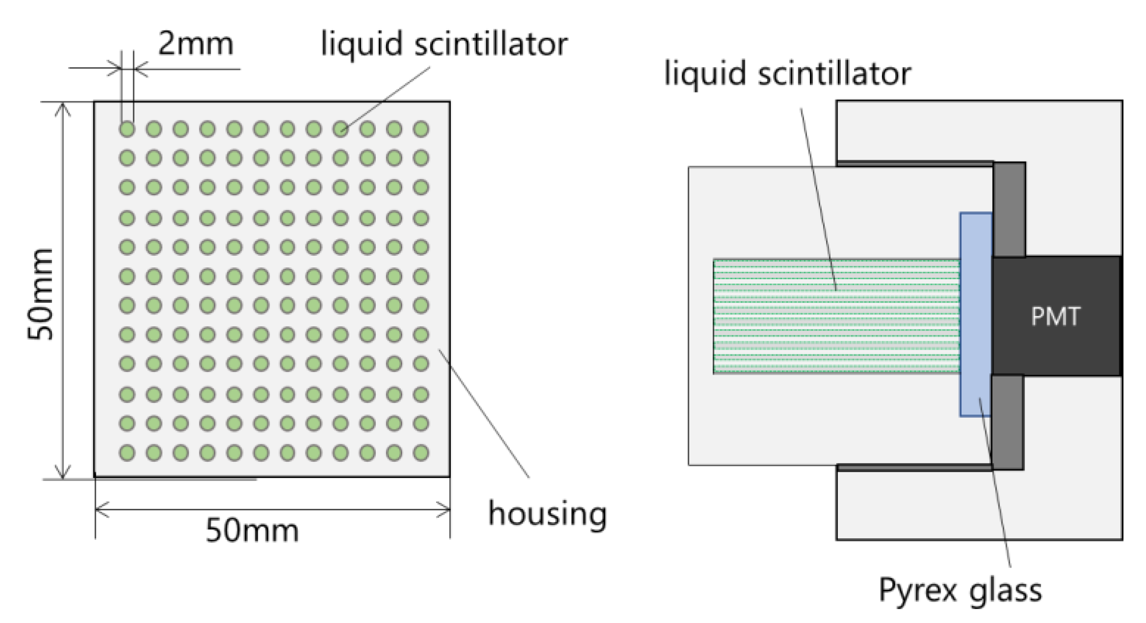
2.2. Capillary-Filled Liquid Scintillation Detector

The detector developed in this study consists of 144 capillaries (50 mm long and 2.0 mm in diameter) in the housing filled with a liquid scintillator, which is coupled to the PMT via Pyrex glass (Figure 2). Depending on the exciting particle, the liquid scintillator has a different decay time constant for a scintillation pulse, which enables the PSD technique. In addition, this detector has directionality because of its long and narrow shape, which is similar to a Sci. Fi. detector.

3. Experiments and Simulations

The liquid scintillator used was an EJ-301 device from Eljen Technology, and the PMT was an H11934-100 device from Hamamatsu. Conventionally, aluminum housing is used in Sci. Fi. detectors, and a previous study showed that multiple reflections from the housing attenuates the scintillation light, thus reducing the detection efficiency [28]. Therefore, in this study, a housing made of Teflon with better reflectivity was also fabricated to compare the detector responses. The anode signal from the PMT was fed directly into a digitizer (DT5751, CAEN). The charge integration method was used for the PSD, where two-time gates (short gate and long gate) were applied to the pulse, and the charges contained in each gate were integrated (Qshort and Qlong) with a 1 GHz sampling rate (Figure 3). This study fixed the short and long gates at 20 ns and 100 ns, respectively. The PSD parameter is defined as PSD = 1 − Qshort/Qlong.
The directionality and PSD capability of the device were investigated in FNL at Tohoku University and OKTAVIAN at Osaka University. In FNL, a detector with an aluminum housing was used; in OKTAVIAN, a detector with a Teflon housing was used. In FNL, the accelerator produced deuterium-deuterium (D-D) and deuterium-lithium (D-Li) neutrons by irradiating a 3 MeV deuterium beam into a D2 or Li target. The energies of the neutrons were ~6 and ~18 MeV, respectively. Their corresponding neutron rates at the target were about 5.3 × 10⁶ neutrons/s and 1.6 × 10⁷ neutrons/s. The distance from the target to the detector was 216 cm, and the angle between the target and the detector was zero degrees. The measurement time was set to 30 min. In OKTAVIAN, a deuterium beam of ~250 keV was injected into a tritium occlusion titanium target to produce D-T neutrons. The typical D-T neutron rate at the target was 109 neutrons/s. The measurement time was set to 10 min. The distance from the target to the detector was 77 cm, and the angle between the target and the detector was fifteen degrees.
To evaluate the directionality, the detector angle was varied from 0° to 30°, 45°, 60°, and 90° using a rotating table. Note that 0° was the direction in which neutrons were incident horizontally on the detector, and 90° was the direction in which neutrons were incident vertically on the detector. A 137Cs gamma-ray source was used to evaluate the attenuation of the scintillation light. The experimental results were compared between the detectors with aluminum and Teflon housings. To simulate the response function of the detector with Teflon housing, SCINFUL-QMD [41], which is available in PHITS (particle and heavy ion transport code system, ver. 3.26) [38], was used. A 252Cf neutron source was used to validate the simulation results.

4. Results and Discussions

4.1. Experimental Results with Fast Neutrons at FNL

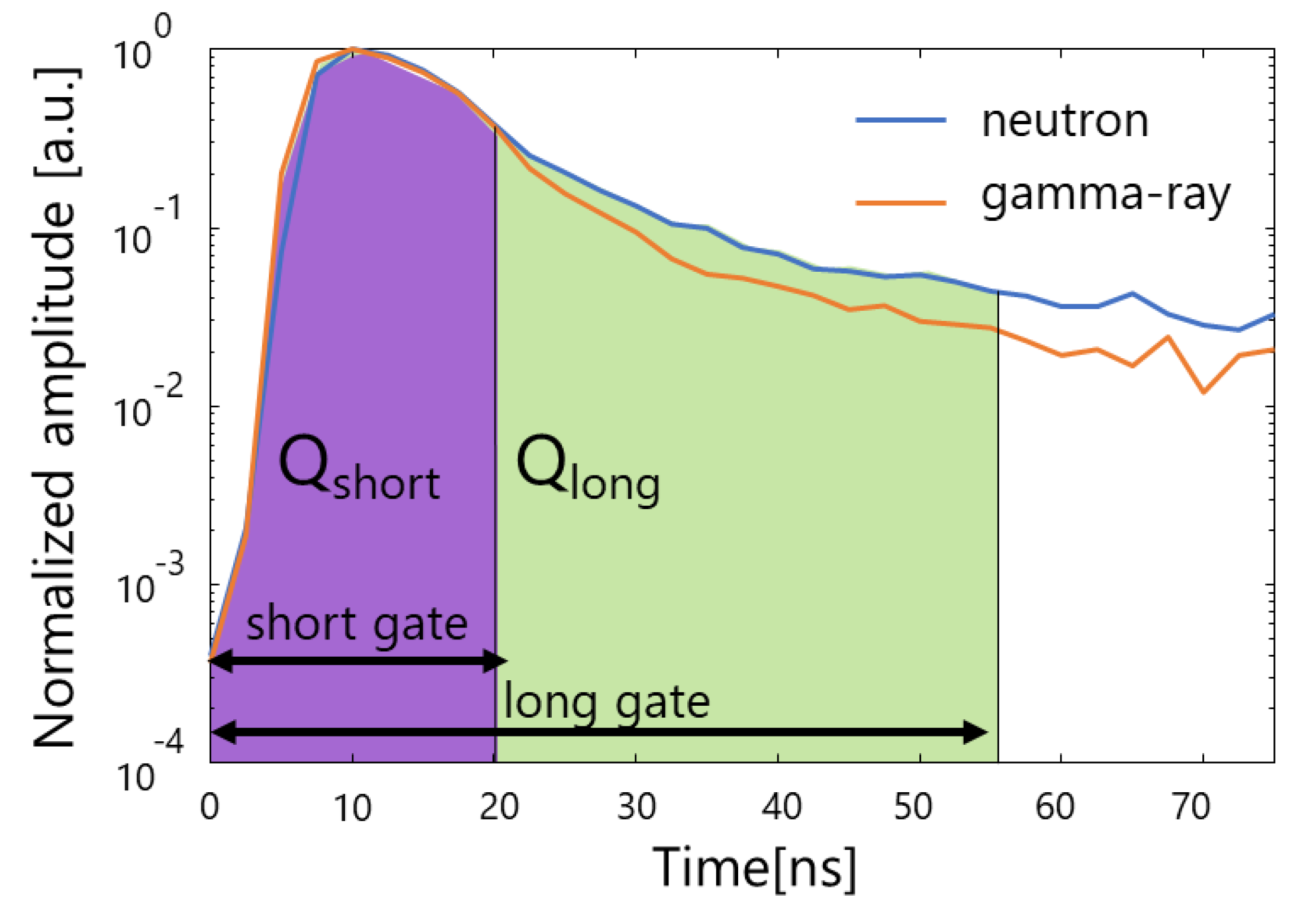
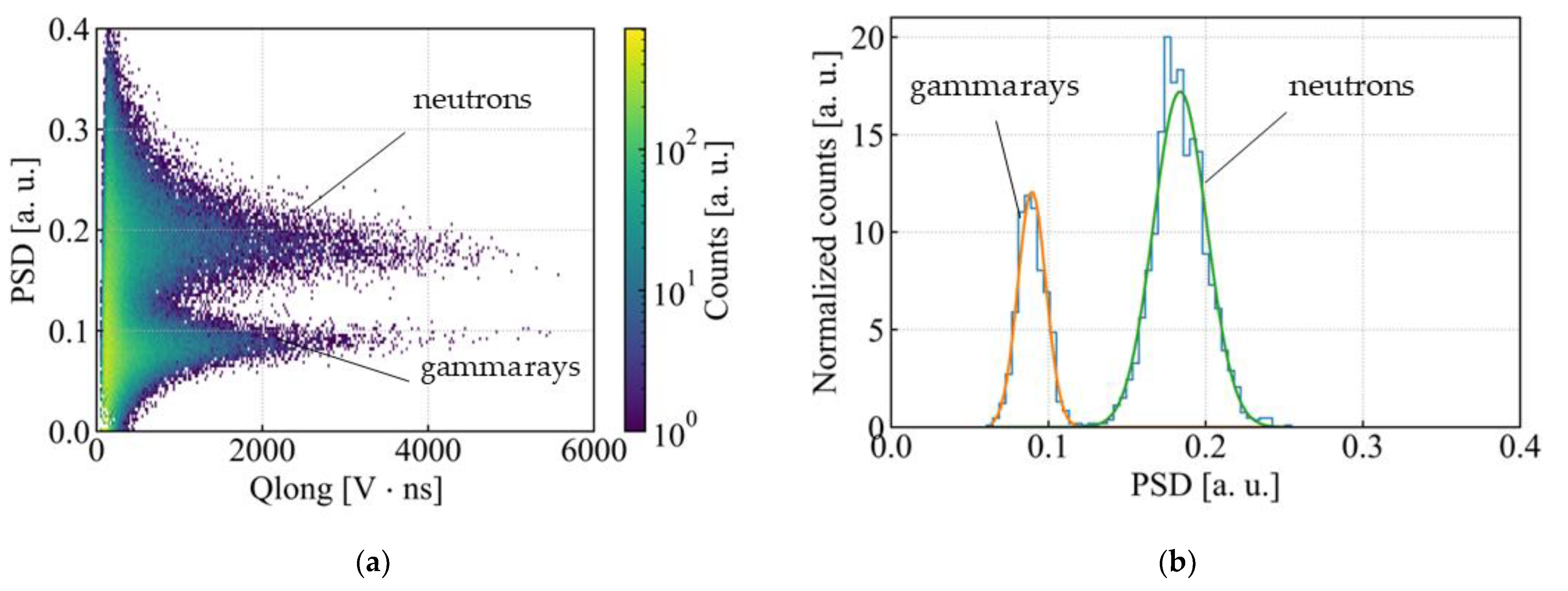
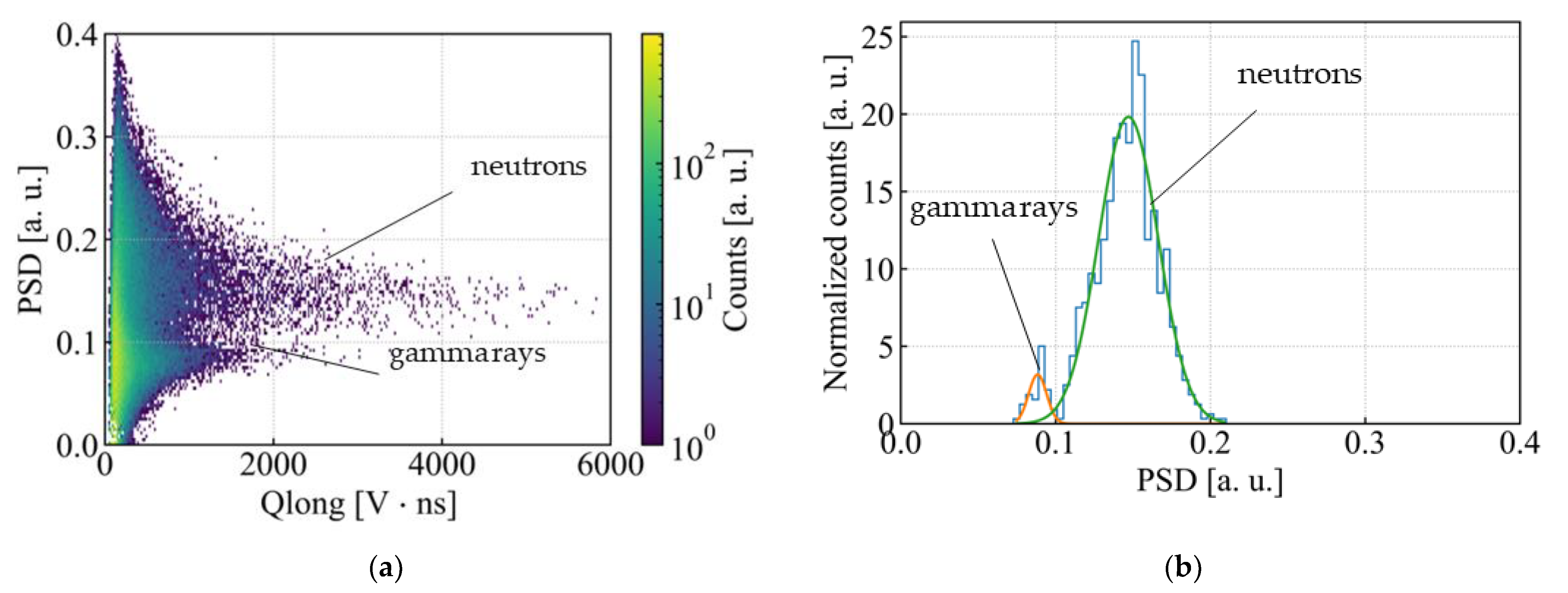
4.1.1. PSD Capability

Figure 4a shows a 2D scatterplot based on Qlong and Qshort when the detector with aluminum housing was irradiated with D-D neutrons. As shown in Figure 4b, events due to gamma-rays and neutrons were discriminated by projecting from the 2D scatterplot in Figure 4 onto the PSD axis and fitting it with a mixed Gaussian distribution. The left and right peaks correspond to events caused by gamma rays and neutrons, respectively. Figure 5a shows a 2D scatterplot based on Qlong and Qshort when the detector with aluminum housing was irradiated with D-Li neutrons. Figure 5b shows the distribution of PSD parameter. The higher energy of the neutrons, as compared to the D-D neutrons, led to a relatively lower number of events due to gamma rays above the threshold. To evaluate the discrimination performance in each distribution, an index of discrimination performance, the figure of merit (FoM), is defined as the following equation:
F o M = d σ 1 + σ 2
where d is the distance between the peaks of each distribution, and the σ 1 and σ 2 are standard deviations. The FoM depended on the incident neutron energy; FoM = 3.7 for D-D neutrons and FoM = 2.5 for D-Li neutrons. Therefore, the optimal long gate and short gate should be selected according to the incident neutron energy.

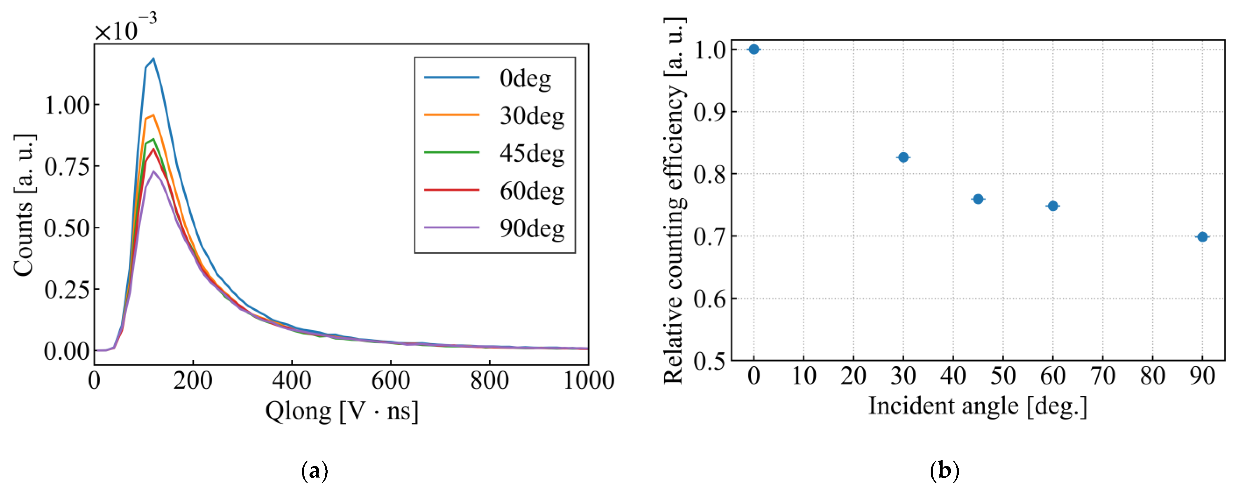
4.1.2. Directionality

Figure 6a shows the dependence of the Qlong distribution on the incident angle for D-D neutrons. The total neutron rate normalized the number of counts based on 3He proportional counter measurements. Figure 6b shows the relative counting rate as a function of the detector angle around Qlong 100–400. Figure 7a shows the dependence of the Qlong distribution on the incident angle for D-Li neutrons. Figure 7b shows the relative counting rate as a function of the detector angle around Qlong 100–400. The larger the detector angle, the smaller the count rate. Therefore, neutrons incident in the front direction could be selectively measured. In addition, the higher the incident energy of the neutrons, the greater the dependence on the incident angle because a longer distance was required for the recoil proton to deposit all of its energy. However, the full-width half-maximum of the relative counting rate was lower than that of the Sci. Fi. detector (20–40 deg) [24,25,26] because the capillary diameter of this detector (2 mm) was longer than that of the Sci. Fi. detector (typically, 1 mm), and the scintillation light generated by axially incident neutrons was significantly attenuated to reduce the detection efficiency, thereby deteriorating the directionality. Furthermore, in ref. [24,25,26], the Sci. Fi. detector showed a dependence on the incident angle in the high-energy region. However, our detector demonstrated this in the low-energy region. Because the pulse height value decreased with the scintillation light attenuation, the overall response spectrum shifted to the lower-energy side. The effects of scintillation photon attenuation are discussed in detail in Section 4.2.

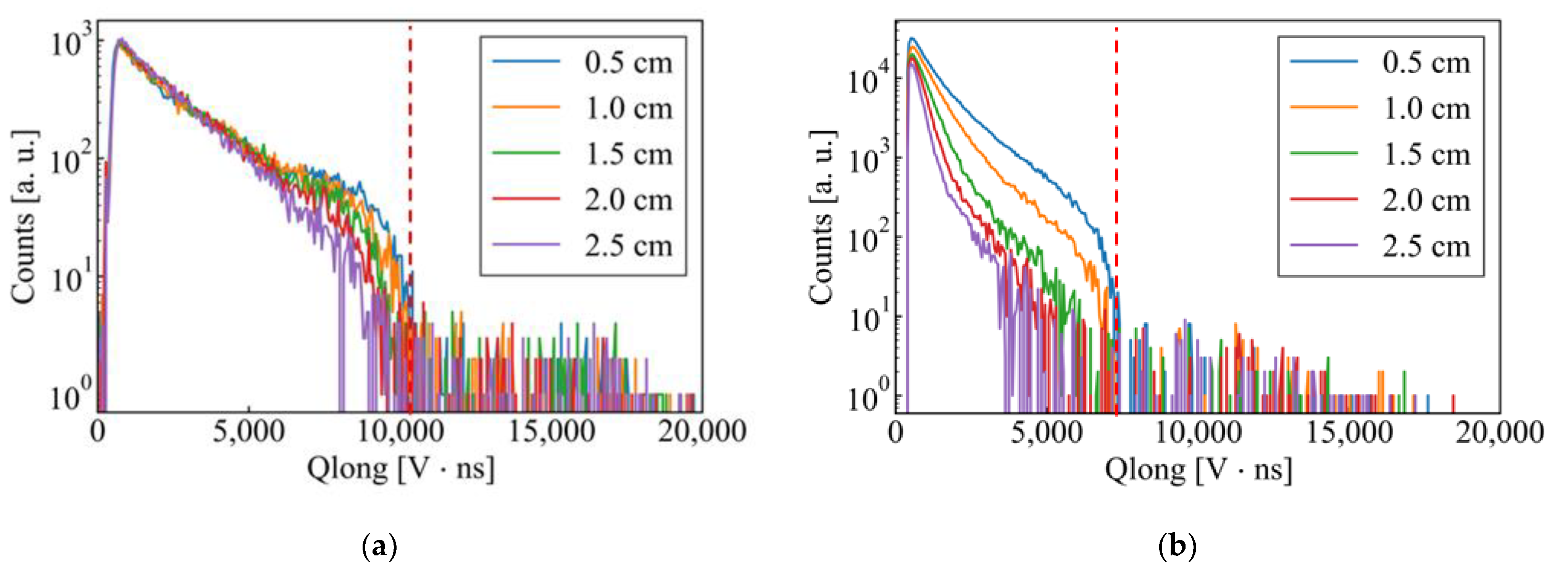
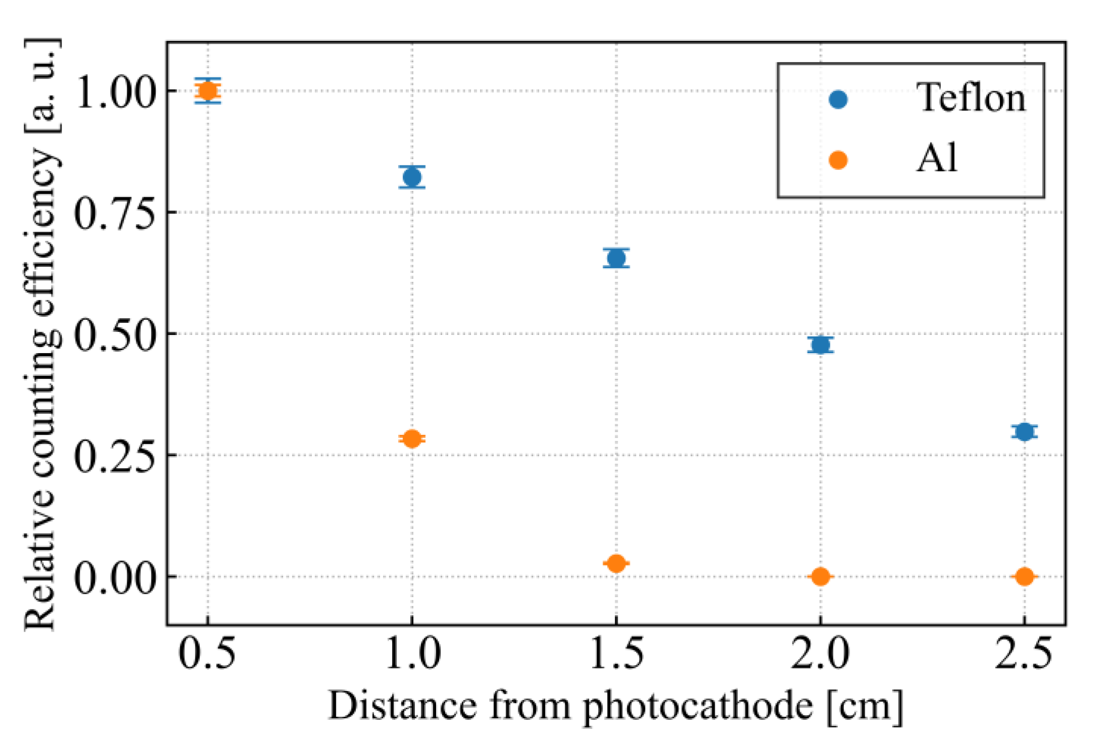
4.2. Experimental Results on Attenuation of Scintillation Photons with a 137Cs Gamma-Ray Source

The scintillation light generated in the liquid scintillator propagated to the photocathode of the PMT through multiple reflections with the housing. For example, the scintillation light generated at a longer distance from the photocathode was expected to have a greater attenuation owing to the increased number of reflections. However, the scintillation light generated closer to the photocathode was anticipated to be almost unattenuated. Therefore, even if the scintillation light originally had the same emission amount, the detectable amount differed depending on its generated position. This effect was more pronounced when the neutrons were axially incident because the number of scintillation events in the front part of the detector was relatively greater than when they were vertically incident.
The attenuation of scintillation light as a function of the generated position was investigated using a 137Cs gamma-ray source. Figure 8 illustrates the experimental configuration. The gamma rays were collimated with a lead block and injected perpendicular to the detector while gradually shifting the incident position by 5 mm. This experiment was conducted for the detectors constructed with an aluminum housing and a Teflon housing and with a Sci. Fi. detector. Gamma rays were irradiated using a collimator with a 5 mm diameter to ensure a sufficient counting rate.
Figure 9a,b show the Qlong distribution as a function of incident position of the gamma rays. Figure 10 also shows the dependence of the relative counting efficiency on the incident position for events with Qlong > 60% of the maximum value. The liquid scintillation detector with the Teflon housing had a relatively low attenuation because its white color had a high reflectivity. The counting efficiency of the liquid scintillation detector with the aluminum housing became close to 0 at 15 mm or more from the photocathode, which means that the scintillation light generated at the entrance region of the detector was almost undetectable. This was because the low reflectivity of the aluminum housing greatly attenuated the scintillation photons.

4.3. Experimental Results with 14 MeV Neutrons at OKTAVIAN

Figure 11a shows the dependence of the Qlong distribution on the indicent angle when D-T neutrons were irradiated to the detector with Teflon housing. Figure 11b shows the relative counting rate as a function of the detector angle for Qlong ≥ 30,000. Like the Sci. Fi. detector, dependence on the incident angle was observed in the high-energy region. The increase in counts at 90° was likely due to errors in the position and angle. The FWHM was approximately 40°, which was better than that of the detector with the aluminum housing. The Teflon housing improved the collection efficiency of the scintillation light, which led to a better directionality than the detector with the aluminum housing. The detector with the aluminum housing showed an angular dependence at the lower-energy part due to the attenuation of scintillation photons; because the range to integrate Qlong needed to be set at a the lower-energy part, the directionality was deteriorated by background gamma rays and low-energy neutrons. On the other hand, the detector with the Teflon housing showed an angular dependence in the high-energy part, which allowed a higher Qlong range, thus improving the directionality. The knee-like distribution of Qlong from 10,000 to 25,000 corresponded to the protons recoiled by the D-T neutrons depositing all of their energy into the liquid scintillator. The response spectrum shifted to the lower-energy side as the incident angle increased. This shift means that this detector was directional to D-T neutrons. The tail-like distribution of Qlong above 25,000 was formed by events generated in the liquid scintillator pool near the photocathode. Because reflections from the housing did not attenuate the scintillation light generated in the liquid scintillation pool, it was efficiently collected, which caused a larger Qlong.

4.4. Comparison between Experimental and Simulation Results

In SCINFUL-QMD, the nuclear reaction between neutrons and carbon nuclei in a cell defined as an organic scintillator was calculated in the SCINFUL mode, and the energy deposited by the generated charged particles was converted to a light output to create a response function. In ref. [28], the authors simulated the detector response of a Sci. Fi. detector using PHITS by considering that the generation efficiency of scintillation photons depends on the excited particle. However, to precisely replicate the detector response, the attenuation of scintillation light should also be considered. SCINFUL-QMD was calculated based on the following equation:
L = L · e x p ( G · D )
where L′ (MeVee) and L (MeVee) are the electron-equivalent energy deposition before and after attenuation, respectively. G is the attenuation coefficient (cm−1), and D (cm) is the distance from the generation position of the scintillation light to the photocathode position. The statistical variation in the light output was assumed to be a Gaussian distribution, and the following equation was used to define its standard deviation:
U = σ 2 + F · L
where σ represents system-specific variations, such as electrical noise. In addition, F∙L expresses the variation in the optical output according to the Poisson distribution, where F denotes the proportional coefficient when the number of generated photons is assumed to be proportional to L. The simulated light output should be digitized for comparison with the experimental results. This was performed using the following equation [42]:
Q l o n g = N · Q E · p m t _ g a i n · e d i g i t i z e r _ c h a r g e _ s e n s i t i v i t y
In this study, the digitizer’s charge sensitivity was set to 20 × 10 15 C/LSB. The PMT gain was 2.0 × 10 5 , and the quantum efficiency (QE) was 0.35 [43]. The number of generated photons (N) was obtained as N = scintillation_yield × L, where the scintillation yield of EJ-301 was 12,000 photons/MeVee [44]. The charge of an electron (e) is 1.6022 × 10⁻¹⁹ C. Substituting these, the following equation can be obtained:
Q l o n g = 6728.4 × L
A geometrical model identical to the actual detector with the Teflon housing was created, and the detector was irradiated with neutrons emitted from a 252Cf neutron source. Figure 12 shows the simulation and experimental results. By adjusting the attenuation coefficient, G, of the scintillation light while fixing the other variables, we reproduced a Qlong distribution similar to the experimental results. In the experiment, the number of counts in the low-energy part was lower than in the simulation results because of the threshold value required to remove background and noise. The response spectrum shifted to higher energies with smaller attenuation coefficients owning to the increased collection efficiency of the scintillation light. The prospect that the experimental results can be reproduced by simulation was obtained, and it is now possible to optimize the detector geometry based on the simulation results.

5. Conclusions

A capillary-filled liquid scintillation detector was developed for triton burnup studies. This detector comes in two variations, utilizing either aluminum or Teflon housings. Through fast neutron irradiation experiments using an accelerator, it was demonstrated that this detector possessed an excellent PSD capability and directionality. The figure of merit for D-D neutrons was determined to be 3.7, while for D-Li neutrons, it was 2.5. Furthermore, the detector with the Teflon housing exhibited an angular resolution of approximately 40° for D-T neutrons. Additionally, the experiments conducted with a 137Cs gamma ray source indicated that the Teflon housing exhibited lower scintillation light attenuation compared to the aluminum housing. This suggests that the use of Teflon housing could contribute to an improved directionality, which led to an improvement in the angular resolution. To validate the results obtained with the Teflon housing, the detector’s response was reproduced using PHITS, a particle transport simulation code. This simulation opened the possibility of optimizing the detector’s geometry based on these replicated experimental results. By employing the PSD method after discriminating between low-energy neutrons and gamma rays based on directionality, more accurate measurements of 14 MeV neutrons in triton burnup studies can be achieved. The effectiveness and applicability of this detector will be further investigated through measurements of secondary D-T neutrons at LHD.

Author Contributions

Conceptualization, E.T., S.S. (Shuhei Sumida), K.S., T.N., K.O. and M.I.; Methodology, E.T., K.S., T.N., K.O. and M.I.; Software, M.T.; Validation, E.T. and S.S. (Shuhei Sumida); Formal analysis, M.T.; Resources, S.M., M.M., S.T. (Sho Toyama), I.M., S.T. (Shingo Tamaki) and S.K.; Data curation, M.T., S.S. (Sangaroon Siriyaporn) and L.L.; Writing—original draft, M.T.; Writing—review & editing, E.T., S.S. (Shuhei Sumida), T.N., K.O. and M.I.; Visualization, M.T.; Supervision, E.T., K.S., K.O. and M.I.; Project administration, E.T. and M.I.; Funding acquisition, E.T., K.O. and M.I. All authors have read and agreed to the published version of the manuscript.

Funding

This work was performed with the support and under the auspices of the NIFS Collaboration Research program (NIFS20KLEH085, NIFS22KIPH003, NIFS23KIPH025).

Data Availability Statement

The data presented in this study are available on request from the corresponding author.

Conflicts of Interest

The authors declare no conflict of interest.

References

  1. Nishitani, T.; Hoek, M.; Harano, H.; Isobe, M.; Tobita, K.; Kusama, Y.; Wurden, G.; Chrien, R. Triton burnup study in JT-60U. Plasma Phys. Control. Fusion 1996, 38, 355. [Google Scholar] [CrossRef]
  2. Jo, J.; Cheon, M.; Kim, J.Y.; Rhee, T.; Kim, J.; Shi, Y.-J.; Isobe, M.; Ogawa, K.; Chung, K.-J.; Hwang, Y. Triton burnup measurements in KSTAR using a neutron activation system. Rev. Sci. Instrum. 2016, 87, 11D828. [Google Scholar] [CrossRef] [PubMed]
  3. Isobe, M.; Ogawa, K.; Nishitani, T.; Miyake, H.; Kobuchi, T.; Pu, N.; Kawase, H.; Takada, E.; Tanaka, T.; Li, S. Neutron diagnostics in the large helical device. IEEE Trans. Plasma Sci. 2018, 46, 2050–2058. [Google Scholar] [CrossRef]
  4. Pu, N.; Nishitani, T.; Ogawa, K.; Isobe, M.; Murakami, S.; Group, L.E. Initial results of triton burnup study in the large helical device. Plasma Fusion Res. 2018, 13, 3402121. [Google Scholar] [CrossRef]
  5. Ogawa, K.; Isobe, M.; Nishitani, T.; Murakami, S.; Seki, R.; Nakata, M.; Takada, E.; Kawase, H.; Pu, N.; Group, L.E. Time-resolved triton burnup measurement using the scintillating fiber detector in the large helical device. Nucl. Fusion 2018, 58, 034002. [Google Scholar] [CrossRef]
  6. Ogawa, K.; Isobe, M.; Nishitani, T.; Murakami, S.; Seki, R.; Nuga, H.; Kamio, S.; Fujiwara, Y.; Yamaguchi, H.; Saito, Y. Energetic ion confinement studies using comprehensive neutron diagnostics in the Large Helical Device. Nucl. Fusion 2019, 59, 076017. [Google Scholar] [CrossRef]
  7. Ogawa, K.; Isobe, M.; Osakabe, M. Progress on integrated neutron diagnostics for deuterium plasma experiments and energetic particle confinement studies in the Large Helical Device during the campaigns from FY2017 to FY2019. Plasma Fusion Res. 2021, 16, 1102023. [Google Scholar] [CrossRef]
  8. Heidbrink, W.W.; Sadler, G.J. The behaviour of fast ions in tokamak experiments. Nucl. Fusion 1994, 34, 535. [Google Scholar] [CrossRef]
  9. Bosch, H.S.; Strachan, J.; Barnes, C.W.; Nieschmidt, E. Calibration of a surface barrier detector for 14-MeV neutron flux measurements on TFTR. Rev. Sci. Instrum. 1988, 59, 1718–1720. [Google Scholar] [CrossRef]
  10. Johnson, L.; Barnes, C.W.; Duong, H.; Heidbrink, W.; Jassby, D.; Loughlin, M.; Roquemore, A.; Ruskov, E.; Strachan, J. Cross calibration of neutron detectors for deuterium-tritium operation in TFTR. Rev. Sci. Instrum. 1995, 66, 894–896. [Google Scholar] [CrossRef] [Green Version]
  11. Ruskov, E.; Heidbrink, W.; Duong, H.; Roquemore, A.; Strachan, J. Measurement of 14 MeV neutrons at TFTR with Si-diode detectors. Rev. Sci. Instrum. 1995, 66, 910–912. [Google Scholar] [CrossRef] [Green Version]
  12. Flammang, R.W.; Seidel, J.G.; Ruddy, F.H. Fast neutron detection with silicon carbide semiconductor radiation detectors. Nucl. Instrum. Methods Phys. Res. Sect. A Accel. Spectrom. Detect. Assoc. Equip. 2007, 579, 177–179. [Google Scholar] [CrossRef]
  13. Angelone, M.; Lattanzi, D.; Pillon, M.; Marinelli, M.; Milani, E.; Tucciarone, A.; Verona-Rinati, G.; Popovichev, S.; Montereali, R.; Vincenti, M. Development of single crystal diamond neutron detectors and test at JET tokamak. Nucl. Instrum. Methods Phys. Res. Sect. A Accel. Spectrom. Detect. Assoc. Equip. 2008, 595, 616–622. [Google Scholar] [CrossRef]
  14. Liu, L.; Liu, A.; Bai, S.; Lv, L.; Jin, P.; Ouyang, X. Radiation resistance of silicon carbide Schottky diode detectors in DT fusion neutron detection. Sci. Rep. 2017, 7, 13376. [Google Scholar] [CrossRef] [Green Version]
  15. Obraztsova, O.; Ottaviani, L.; Klix, A.; Döring, T.; Palais, O.; Lyoussi, A. Comparing the response of a SiC and a sCVD diamond detectors to 14-MeV neutron radiation. IEEE Trans. Nucl. Sci. 2018, 65, 2380–2384. [Google Scholar] [CrossRef]
  16. Rebai, M.; Rigamonti, D.; Cancelli, S.; Croci, G.; Gorini, G.; Cippo, E.P.; Putignano, O.; Tardocchi, M.; Altana, C.; Angelone, M. New thick silicon carbide detectors: Response to 14 MeV neutrons and comparison with single-crystal diamonds. Nucl. Instrum. Methods Phys. Res. Sect. A Accel. Spectrometers Detect. Assoc. Equip. 2019, 946, 162637. [Google Scholar] [CrossRef]
  17. Schmid, G.; Koch, J.; Lerche, R.; Moran, M. A neutron sensor based on single crystal CVD diamond. Nucl. Instrum. Methods Phys. Res. Sect. A Accel. Spectrom. Detect. Assoc. Equip. 2004, 527, 554–561. [Google Scholar] [CrossRef]
  18. Xu, P.; Yu, Y.; Zhou, H. Fabrication of single-crystal diamond neutron detector and its application in 14.1 MeV neutron detection in deuteriumtritium fusion experiment. Plasma Sci. Technol. 2023, 25, 075101. [Google Scholar] [CrossRef]
  19. Ogawa, K.; Isobe, M.; Weiss, C.; Griesmayer, E.; Sangaroon, S.; Takada, E.; Masuzaki, S.; Ohtani, H.; Liao, L.; Tamaki, S. Fusion product diagnostics based on commercially available chemical vapor deposition diamond detector in large helical device. J. Instrum. 2023, 18, P01022. [Google Scholar] [CrossRef]
  20. Kobayashi, M.I.; Yoshihashi, S.; Ogawa, K.; Isobe, M.; Miwa, M.; Toyama, S.; Matsuyama, S.; Osakabe, M. Measurement of 6Li burn-up reaction rate using a single crystal CVD diamond detector under fast neutron irradiation environment. Fusion Eng. Des. 2023, 193, 113799. [Google Scholar] [CrossRef]
  21. Sailor, W.; Barnes, C.W.; Chrien, R.; Wurden, G. Conceptual design for a scintillating-fiber neutron detector for fusion reactor plasma diagnostics. Rev. Sci. Instrum. 1995, 66, 898–900. [Google Scholar] [CrossRef] [Green Version]
  22. Wurden, G.; Chrien, R.; Barnes, C.W.; Sailor, W.; Roquemore, A.; Lavelle, M.; O’gara, P.; Jordan, R. Scintillating-fiber 14 MeV neutron detector on TFTR during DT operation. Rev. Sci. Instrum. 1995, 66, 901–903. [Google Scholar] [CrossRef] [Green Version]
  23. Nishitani, T.; Isobe, M.; Wurden, G.; Chrien, R.; Harano, H.; Tobita, K.; Kusama, Y. Triton burnup measurements using scintillating fiber detectors on JT-60U. Fusion Eng. Des. 1997, 34, 563–566. [Google Scholar] [CrossRef]
  24. Ogawa, K.; Isobe, M.; Nishitani, T.; Takada, E.; Kawase, H.; Amitani, T.; Pu, N.; Jo, J.; Cheon, M.; Kim, J. High detection efficiency scintillating fiber detector for time-resolved measurement of triton burnup 14 MeV neutron in deuterium plasma experiment. Rev. Sci. Instrum. 2018, 89, 10I101. [Google Scholar] [CrossRef] [PubMed]
  25. Takada, E.; Fujisaki, A.; Nakada, N.; Isobe, M.; Ogawa, K.; Nishitani, T.; Tomita, H. Development of fast-neutron directional detector for fusion neutron profile monitor at LHD. Plasma Fusion Res. 2016, 11, 2405020. [Google Scholar] [CrossRef] [Green Version]
  26. Ogawa, K.; Isobe, M.; Sangaroon, S.; Takada, E.; Nakada, T.; Murakami, S.; Jo, J.; Zhong, G.; Zhang, Y.; Tamaki, S. Time-resolved secondary triton burnup 14 MeV neutron measurement by a new scintillating fiber detector in middle total neutron emission ranges in deuterium large helical device plasma experiments. AAPPS Bull. 2021, 31, 20. [Google Scholar] [CrossRef]
  27. Pu, N.; Nishitani, T.; Ogawa, K.; Isobe, M. Scintillating fiber detectors for time evolution measurement of the triton burnup on the Large Helical Device. Rev. Sci. Instrum. 2018, 89, 10I105. [Google Scholar] [CrossRef]
  28. Takada, E.; Amitani, T.; Fujisaki, A.; Ogawa, K.; Nishitani, T.; Isobe, M.; Jo, J.; Matsuyama, S.; Miwa, M.; Murata, I. Design optimization of a fast-neutron detector with scintillating fibers for triton burnup experiments at fusion experimental devices. Rev. Sci. Instrum. 2019, 90, 043503. [Google Scholar] [CrossRef]
  29. Isobe, M.; Ogawa, K.; Sangaroon, S.; Kamio, S.; Fujiwara, Y.; Osakabe, M. Recent development of neutron and energetic-particle diagnostics for LHD deuterium discharges. J. Instrum. 2022, 17, C03036. [Google Scholar] [CrossRef]
  30. Ogawa, K.; Isobe, M.; Kamio, S.; Nuga, H.; Seki, R.; Sangaroon, S.; Yamaguchi, H.; Fujiwara, Y.; Takada, E.; Murakami, S. Studies of energetic particle transport induced by multiple Alfvén eigenmodes using neutron and escaping energetic particle diagnostics in Large Helical Device deuterium plasmas. Nucl. Fusion 2022, 62, 112001. [Google Scholar] [CrossRef]
  31. Lee, S.; Nam, Y.; Bak, J.; Juhn, J.; Lee, J.; Lee, K.; Seo, S.; Ko, W.; Ko, J.; Lee, J. Overview and recent progress of KSTAR diagnostics. J. Instrum. 2022, 17, C01065. [Google Scholar] [CrossRef]
  32. Kawase, H.; Ogawa, K.; Nishitani, T.; Pu, N.; Isobe, M.; Group, L.E. Evaluation of spatial resolution of neutron profile monitor in LHD. IEEE Trans. Plasma Sci. 2018, 47, 462–465. [Google Scholar] [CrossRef]
  33. Isobe, M.; Ogawa, K.; Sangaroon, S.; Zhong, G.; Fan, T. Recent Progress of Neutron Spectrometer Development for LHD Deuterium Plasmas. Plasma Fusion Res. 2022, 17, 2402008. [Google Scholar] [CrossRef]
  34. Ishikawa, M.; Nishitani, T.; Morioka, A.; Takechi, M.; Shinohara, K.; Shimada, M.; Miura, Y.; Nagami, M.; Kaschuck, Y.A. First measurement of neutron emission profile on JT-60U using Stilbene neutron detector with neutron-gamma discrimination. Rev. Sci. Instrum. 2002, 73, 4237–4242. [Google Scholar] [CrossRef]
  35. Itoga, T.; Ishikawa, M.; Baba, M.; Okuji, T.; Oishi, T.; Nakhostin, M.; Nishitani, T. Fast response neutron emission monitor for fusion reactor using stilbene scintillator and flash-ADC. Radiat. Prot. Dosim. 2007, 126, 380–383. [Google Scholar] [CrossRef]
  36. Baba, M.; Takada, M.; Iwasaki, T.; Matsuyama, S.; Nakamura, T.; Ohguchi, H.; Nakao, T.; Sanami, T.; Hirakawa, N. Development of monoenergetic neutron calibration fields between 8 keV and 15 MeV. Nucl. Instrum. Methods Phys. Res. Sect. A Accel. Spectrom. Detect. Assoc. Equip. 1996, 376, 115–123. [Google Scholar] [CrossRef]
  37. Schmid, G.; Koch, J.; Lerche, R.; Moran, M. Status of OKTAVIAN I and proposal for OKTAVIAN II. Nucl. Sci. Eng. 1990, 106, 249–265. [Google Scholar]
  38. Sato, T.; Iwamoto, Y.; Hashimoto, S.; Ogawa, T.; Furuta, T.; Abe, S.-i.; Kai, T.; Tsai, P.-E.; Matsuda, N.; Iwase, H. Features of particle and heavy ion transport code system (PHITS) version 3.02. J. Nucl. Sci. Technol. 2018, 55, 684–690. [Google Scholar] [CrossRef] [Green Version]
  39. Nishitani, T.; Ogawa, K.; Nishimura, K.; Isobe, M. Radiation field estimation for the diagnostic and control components by Monte Carlo neutronics calculations with LHD 3-dimensional modeling. Plasma Fusion Res. 2016, 11, 2405057. [Google Scholar] [CrossRef] [Green Version]
  40. Sain, G. Available online: https://www.crystals.saint-gobain.com/radiation-detection-scintillators/fibers (accessed on 3 July 2023).
  41. Satoh, D.; Sato, T. Improvements in the particle and heavy-ion transport code system (PHITS) for simulating neutron-response functions and detection efficiencies of a liquid organic scintillator. J. Nucl. Sci. Technol. 2022, 59, 1047–1060. [Google Scholar] [CrossRef]
  42. Das, S.; Kashyap, V.K.S.; Mohanty, B. Energy calibration of EJ-301 scintillation detector using unfolding methods for fast neutron measurement. Nucl. Instrum. Methods Phys. Res. Sect. A Accel. Spectrom. Detect. Assoc. Equip. 2022, 1042, 167405. [Google Scholar] [CrossRef]
  43. Hamamatsu. Available online: https://www.hamamatsu.com/content/dam/hamamatsu-photonics/sites/documents/99_SALES_LIBRARY/etd/R11265U_H11934_TPMH1336E.pdf (accessed on 2 July 2023).
  44. Eljen Technology. Available online: https://eljentechnology.com/products/liquid-scintillators/ej-301-ej-309 (accessed on 2 July 2023).
Figure 1. Structure of a Sci. Fi. detector. Pulse signals from an axially incident neutron (orange) and an obliquely incident neutron (blue).
Electronics 12 03219 g001
Figure 2. Structure of a capillary-filled liquid scintillation detector.
Electronics 12 03219 g002
Figure 3. Definition of the short gate and long gate to calculate Qshort and Qlong in the charge integration method.
Electronics 12 03219 g003
Figure 4. (a) Two-dimensional scatter plots based on Qshort and Qlong. (b) Distribution of PSD parameters above Qlong 2000. D-D neutrons were irradiated to the detector with an aluminum housing.
Electronics 12 03219 g004
Figure 5. (a) Two-dimensional scatter plots based on Qshort and Qlong. (b) Distribution of PSD parameters above Qlong 2000. D-Li neutrons were irradiated to the detector with an aluminum housing.
Electronics 12 03219 g005
Figure 6. (a) Dependence of Qlong distribution on incident angle. (b) The relative counting rate as a function of the detector angle around Qlong 100–400. D-D neutrons were irradiated to the detector with aluminum housing. The counting rate was normalized by the total neutron rate based on 3He proportional counter measurements.
Electronics 12 03219 g006
Figure 7. (a) Dependence of Qlong distribution on incident angle. (b) The relative counting rate as a function of the detector angle around Qlong 100–400. D-Li neutrons were irradiated to the detector with aluminum housing. The counting rate was normalized by the total neutron rate based on 3He proportional counter measurements.
Electronics 12 03219 g007
Figure 8. Experimental setup to investigate the relationship between the generation position of scintillation light and its attenuation.
Electronics 12 03219 g008
Figure 9. (a) Qlong distribution for the liquid scintillation detector with the Teflon housing as a function of gamma ray incident position. The measurement time was 600 s. (b) Qlong distribution for the liquid scintillation detector with the Al housing as a function of gamma ray incident position. The measurement time was 18,000 s.
Electronics 12 03219 g009
Figure 10. Comparison of counting efficiencies of the aluminum housing and Teflon housing as a function of gamma ray incident position. The counting efficiency was normalized based on an incident position of 0.5 cm from the photocathode. The threshold of Qlong was 60% of the maximum Qlong value (red dashed line in Figure 9a,b) for each distribution.
Electronics 12 03219 g010
Figure 11. (a) Dependence of Qlong distribution on incident angle. (b) The relative counting rate as a function of the detector angle with Qlong ≥ 20,000. D-T neutrons were irradiated to the detector with Teflon housing. The counting rate was normalized by the total neutron rate based on 3He proportional counter measurements.
Electronics 12 03219 g011
Figure 12. Comparison of Qlong distributions obtained from simulation and experimental results.
Electronics 12 03219 g012
Disclaimer/Publisher’s Note: The statements, opinions and data contained in all publications are solely those of the individual author(s) and contributor(s) and not of MDPI and/or the editor(s). MDPI and/or the editor(s) disclaim responsibility for any injury to people or property resulting from any ideas, methods, instructions or products referred to in the content.

