
Broad Stopband, Low-Loss, and Ultra-Compact Dual-Mode Bandpass Filter Based on HMSIRC

1
Engineering Optimization and Modeling Center, Reykjavik University, 102 Reykjavik, Iceland
2
Faculty of Electronics, Telecommunication and Informatics, Gdansk University of Technology, 80-233 Gdansk, Poland
*
Author to whom correspondence should be addressed.
Electronics 2023, 12(13), 2831; https://doi.org/10.3390/electronics12132831
Submission received: 15 May 2023
/
Revised: 22 June 2023
/
Accepted: 24 June 2023
/
Published: 26 June 2023
(This article belongs to the Special Issue Substrate Integrated Circuits and Antennas)
Abstract
:In this investigation, an ultra-compact dual-mode bandpass filter (BPF) with a wide stopband response is realized by using a half-mode substrate-integrated rectangular cavity (HMSIRC). The HMSIRC resonator is designed with a cavity that is rectangular in shape and has metallic vias along three of the sides. The fourth side is open-ended and contains microstrip feed lines. For the purpose of constructing a magnetic wall, a rectangular slot is cut into each of the HMSIRC’s three edges. In order to produce an electrical wall that may generate a variety of resonances, the side with the open edges is provided with a single metallic via in the center. After that, a second-order BPF is generated by loading a transverse slot in the middle of the BPF, which enables independent frequency regulation of the mode frequencies. The eigen-mode analysis; field distributions; coupling matrix; and full-wave simulation of the proposed HMSIRC filter topology are used to develop the working principle of the filter. A second-order BPF is realized, constructed, and experimentally validated in order to provide evidence that the theory is correct. The BPF prototype achieves satisfactory performance thanks to its compact footprint of 0.028 λg2; its broad passband of 15.9%; its low insertion loss of 0.41 dB; and its wide stopband of 4.36 f0 with a rejection level greater than 20 dB. Both the measured and EM-simulated responses of the BPF are very consistent with one another.
1. Introduction
The development of bandpass filters (BPFs) with low cost, compact size, better frequency selectivity, and broadband suppression has been greatly influenced by the incredible advancements in wireless communication technology. In filter design for base stations, waveguide structures are frequently used due to their low loss, high power handling capability, and high Q-factor. However, integrating a rectangular waveguide with other planar microwave components is costly and challenging. Recently, substrate-integrated waveguides (SIW) have received a lot of attention because they are inexpensive, lightweight, feature low insertion loss, are simple to fabricate, and work well with other planar circuits. These characteristics make them ideal for meeting the high-performance demands imposed on filter designs [1,2,3].
Several BPFs have been constructed using SIW technology [4,5,6,7,8,9,10,11,12,13,14,15,16,17,18,19,20,21,22,23,24,25,26,27,28,29,30,31,32,33,34,35,36,37,38,39,40,41,42,43,44,45,46,47]. Narrow and wide-band BPFs have been realized using the SIW coaxial cavity, as described in [4]. The authors of [5] describe a three-pole BPF employing a dual-mode circular SIW cavity with tunable transmission zeros. To implement a SIW filter with a wide stopband, [6] uses a variant of the mode suppression technique. There is an analysis and implementation of filters based on quarter-mode substrate integrated waveguides (QMSIWs) in [7]. The authors of [8] describe a BPF with a wide upper stopband response that was built using a multi-layered SIW. Triple-mode BPFs based on a SIW square cavity filled with CSRRs are shown in [9]. The authors of [10] describe SIW square cavities with orthogonal and in-line ports that are used to build BPFs with adaptable outputs. The authors of [11] describe bandpass filters that have been created using dual-mode SIW cavities operating within various boundaries. Combining QMSIW and EMSIW cavities allows for a small BPF with a wide stopband response, as shown in [12]. The authors of [13] describe a wideband filter and diplexer using a dual-mode SIW cavity with variable reactions. Using dual-mode SIW radial cavities, a wideband BPF has been realized [14]. Dual-mode miniaturized BPFs have been realized using half-mode SIW cavities [15]. The authors of [16] describe how it has been suggested that dual-mode SIW cavities be used to construct box-like BPFs with a wide stopband response. The use of perturbed SIW cavities has allowed for the development of high-order BPFs, as shown in [17]. Using a combination of microstrip technology and SIW, the authors of [18] explore the fabrication of a small BPF with a wide stopband response. Using half-mode SIW with stepped-impedance resonators, [19] creates a compact bandpass filter. A broadband SIW bandpass filter based on electromagnetic bandgap (EBG) units for wide stopband response has been constructed with good selectivity [20].
A HMSIW fan-shaped circular cavity has been examined in order to build a bandpass filter with decreased size and order-extensible capabilities [21]. Within the scope of this study, a bandpass filter of the second order was upgraded to a filter of the fourth order without the cavity’s actual size having to be increased. A HMSIW cavity was used to construct planar bandpass filters with a small size for the research presented in [22]. These fourth-order filters have a fractional bandwidth of 31.8%, one/two transmission zeros, and a reduced footprint area of 0.159 λg2. Using a T-septum HMSIW cavity, third-order bandpass filters have been created and described in [23]. These filters have an insertion loss of less than 2.61 dB and a fractional bandwidth of 17.77%, while also having a wide stopband of 10.37 f0. Higher-order SIW resonators were used in the construction of a narrow-band filter that was published in [24]. This filter offers high selectivity, a wide stopband, and three transmission zeros. Utilizing a SIW cavity equipped with perturbing vias and a complementary split-ring resonator, an application-specific bandpass filter for frequencies below 6 GHz was developed and described in [25]. In addition to having a fractional bandwidth of 1.16% and high selectivity, this filter has an insertion loss of 2.9 dB. The article [27] describes the construction of a bandpass filter for X-band applications that is based on a dual-mode SIW cavity. This filter has two transmission zeros located at 10.75 GHz and 13.3 GHz, and it operates at a frequency of 12 GHz. The fractional bandwidth of this filter is 11%. Utilizing a double-layer HMSIW resonator resulted in the development of a bandpass filter that was described in reference [28]. This filter makes use of a microstrip defect structure in order to provide a wide stopband response. Using a rectangular SIW cavity filled with a D-shaped ring resonator, the research paper [29] describes the construction of a bandpass filter with two bands. Applications that need frequencies lower than 6 GHz may make use of this filter since it works at 2.66 and 3.54 GHz. The authors of [30] describe a SIW filter with asymmetric responses. This filter also makes use of a non-resonating node and positive coupling in order to improve its selectivity. A bandpass filter that is based on SIW cavities has been constructed and described in [31]. This filter achieves harmonic suppression by combining the functionality of the SIW cavity with that of interdigital resonators. The authors of [32] describe a broadband bandpass filter on HMSIW cavities with a size reduction that has been created. Transmission zeros and favorable stopband responses are generated using a three-stage stepped impedance resonator in this filter. An in-line HMSIW cavity is used to create a narrow-band bandpass filter, as demonstrated in [33]. This filter enhances selectivity by generating limited transmission zeros using interdigital slots to create quasi-elliptic responses. The authors of [34] describe a bandpass filter operating at 6 GHz for 5G applications that has been realized using a rectangular SIW cavity. This filter employs D-shaped resonators for size reduction and wide stopband responses. The authors of [35] describe the creation of a bandpass filter that is based on a rectangular SIW cavity that is loaded with many complimentary split-ring resonators. This filter has an insertion loss of 1.5 dB, a stopband response that ranges from 6.4 GHz to 7.8 GHz, and a fractional bandwidth that is 30% wider than the full bandwidth.
A broadband bandpass filter has been realized using SIW in conjunction with defective ground structures [36]. This 8.98 GHz operating filter has a fractional bandwidth of 47.4%, an insertion loss of 1.5 dB, and a strong roll-off factor. The authors of [37] describe a SIW cavity loaded with composite right/left-handed transmission lines and complementary split-ring resonators that is used to create a dual-frequency bandpass filter. The filter has a 3% and a 4.2% bandwidth at its 5 GHz and 7.5 GHz resonant frequencies, respectively. The authors of [38] describe a flexible bandpass filter based on a SIW hexagonal resonator. This filter has an insertion loss of 2.01 dB and a fractional bandwidth of 2.92 percent. The authors of [39] describe a SIW bandpass filter consisting of two resonators and three inverters. A bandpass filter has been constructed utilizing a SIW cavity with iris resonators, as described in [40]. The frequency of operation for this filter is 9.77 GHz, and it has a fractional bandwidth of 12.17% and an insertion loss of 1.19 dB. The paper [41] describes the construction of a bandpass filter using a SIW cavity with a defective ground structure in order to get wideband responses. With a passband ranging from 3.0 GHz to 11.0 GHz, an insertion loss of 1.2 dB, and a notched band, this filter is able to achieve a smaller footprint. The authors of [42] describe a narrow bandpass filter that has been realized by using a rectangular SIW cavity loaded with inductive posts on the top surface. The center frequency of this filter is 12.2 GHz, and it has an insertion loss of 1.22 dB and a fractional bandwidth of 1.475%. The authors of [43] describe a dual-mode bandpass filter that has been constructed by using a SIW cavity loaded with cross-shaped slots. This filter has a fractional bandwidth of 9.1% at the center frequency of 7.5 GHz and two transmission zeros at 12.5 GHz and 15 GHz, respectively. Using a rectangular SIW cavity in conjunction with stepped impedance resonators, the authors of [44] were able to create a bandpass filter with a reduced size. This filter has a footprint size of 0.3 λg2, it works at 4.8 GHz, it offers four transmission zeros, and it has a fractional bandwidth of 13%. The authors of [45] describe a dual-mode bandpass filter operating at 5.8 GHz, which has been constructed by utilizing a SIW cavity loaded with a circular patch slot. The authors of [46] describe a bandpass filter with high design flexibility that has been realized by using a SIW cavity in non-resonating mode. The authors of [47] describe a rectangular SIW cavity loaded with two pairs of complementary rectangular split-ring resonators. This filter has a transmission zero at 5.9 GHz, an insertion loss of 2.4 dB, and a bandwidth of 320 MHz at 3 dB.
An ultra-compact dual-mode bandpass filter (BPF) with a broad stopband response is constructed in this study by using a half-mode substrate-integrated rectangular cavity (HMSIRC). Eigen-mode analysis, field distributions, the coupling matrix, and full-wave simulation of the proposed HMSIRC filter topology are used to construct the filter’s working theory. Realization, prototyping, and experimental validation of a second-order BPF are accomplished to prove the concept. The filter exhibits the following key features:
- (i)
- It occupies a footprint area of only 0.028 λg2, which is extremely small compared to the dual-mode BPFs that have previously been reported;
- (ii)
- Its insertion loss is 0.41 dB;
- (iii)
- It exhibits a passband of 15.9%, a broad stopband response of 4.36 f0, and a rejection level of 20 dB.
2. Design and Analysis of the HMSIRC-Based Bandpass Filter
2.1. Configuration and Working Principles
The proposed dual-mode bandpass filter layout and coupling topology are shown in Figure 1. The filter is constructed using a transverse slot, an open-ended slot, a metallic via, and a half-mode substrate-integrated rectangular cavity (HMSIRC). Initially, an HMSIRC is created by the longitudinal bisection of the SIRC. The mode frequencies of the HMSIRC are determined as [2]:
where is the diameter S0 of the vias, and their longitudinal distance S1 is chosen by applying the following criteria: S0/λ ≤ 0.1 and S0/S1 ≥ 0.5. This is to keep the radiation losses reasonably low [2]. Next, a magnetic wall is created by etching an open-ended slot in the cavity with metallic vias on each of its three sides.
Subsequently, a metallic via is placed in the middle of the cavity, which generates an electric wall. These arrangements provide multiple modes of resonance. Finally, a transverse slot is introduced at the middle of the cavity to control the mode frequencies, which enables us to develop a dual-mode bandpass filter. The top of the HMSIW is then etched with a rectangular ring slot, which increases the capacitive loading of the cavity. This, in turn, provides an operating frequency that is lower than the cutoff frequency of the cavity. Because of this result, it is possible to accomplish size reduction. The substrate used to create the filter is Roger’s RO4003C, which has a thickness of 0.508 mm, a permittivity of 3.38, and a loss tangent of 0.0021.
2.2. Synthesis of a Dual-Mode Bandpass Filter
The suggested dual-mode BPF using the half-mode SIRC cavity is shown in Figure 1a. The rectangular slot along the three sides of the half-mode cavity produces a magnetic wall, whereas a centrally loaded metallic via creates an electric wall. This arrangement generates various modes. Figure 2 exhibits the distributions of the electric field to express the various modes. Without loading the slots, the resonant frequencies of the HMSIW cavity modes TE110, TE210, TE310, and TE120 are 3.45 GHz, 4.35 GHz, 5.52 GHz, and 6.35 GHz, respectively. Because of the slot loading, the resonant frequencies of these modes are decreased due to the increase in capacitive loading on the top surface of the cavity, which results in the realization of a second-order filter at a lower frequency. Figure 3 depicts the distributions of the vector H-field to examine the influence of the transverse slot. Since the transverse slot is perpendicular to the vector H-field directions of the TE110 and TE120 modes, as shown in Figure 3a,d, it has a profound effect on these modes. From Figure 3b,c, it is observed that the H-filed direction of the modes TE210 and TE310 is parallel to the transverse slot, which has no significant effect on the resonant frequencies. The effect of the length L3 of the transverse slot on the resonant frequencies of the modes is shown in Figure 4. As it can be seen, the resonant frequencies of the TE110 and TE120 modes are decreased by increasing the length of the transverse slot, whereas there is no significant change in the resonant frequencies of the TE210 and TE310 modes. It is inferred that the length of the transverse slot can control the resonant frequency of the modes that allow us to realize a second-order BPF.
The coupling coefficient Kj,j+1, the source quality factors QS, and the load quality factor QL can be determined as [26]:
where the center frequency and the 3 dB bandwidth are denoted by f0 and f±3dB; fm1 and fm2 stand for mode frequencies. The transverse slot’s length allows us to predict the bandwidth of the filter. The unloaded quality factor Qu is computed to be 382 using eigen-mode analysis and factoring in losses attributable to radiation, conductor, and dielectric.
For verification, a second-order BPF has been synthesized. The circuit exhibits a center frequency of 0.835 GHz, a return loss of 26.3 dB, and a relative bandwidth of 5.43%. The synthesis method of [3] has been used to compute the coupling coefficient, external quality factor, and coupling matrix as K12 = 0.0528, QS = QL = 6.5, and
The BPF’s coupling coefficient and quality factor are controlled via a transverse slot. Figure 5 shows how the coupling coefficient of the BPF varies with the slot width. The coupling coefficient K12 is shown to decrease with increasing slot width W3. S-parameters calculated by the coupling matrix and electromagnetic simulation for the proposed BPF are shown in Figure 6. The total loss of the proposed BPF is attributed to radiation loss, dielectric loss, and conductor loss. Figure 7 shows the estimated losses of the second-order BPF. As illustrated, the total loss, dielectric plus radiation loss, and radiation loss are all less than 0.143, 0.095, and 0.075, respectively. As a result, the proposed BPF exhibits a very low insertion loss of 0.41 dB.
2.3. Analysis of Insertion Loss
In this subsection, insertion loss owing to frequency enhancement is investigated. By lowering the value of the cavity parameter Ls, the suggested HMSIW-based bandpass filter achieves a higher resonant frequency. In order to observe the effect on insertion loss with an increase in frequency, we varied the parameter Ls and obtained the EM simulations. Figure 8 shows the insertion losses at different frequencies with varying Ls. It is found that there are no significant changes in the insertion loss when frequency increases. The insertion loss at each center frequency is determined as shown in Table 1. As the resonant frequency rises from 0.839 GHz to 0.938 GHz, the insertion loss rises from 0.362 dB to 0.37 dB, which is only a 2.2% increase.
2.4. Analogous Circuit Model of a Second-Order Bandpass Filter
The order of the filter can be determined either by the number of poles or the number of zeros; whichever number is higher will determine the order. The bandpass filter based on HMSIW that was presented is a second-order filter due to the fact that it creates two poles. In order to verify the filter, an analogous circuit model is created for the suggested second-order HMSIW-based bandpass filter, as shown in Figure 9. The metallic vias of the HMSIW may be represented as a two-wire transmission line and characterized as a shunt inductor by Lmv. The magnetic and electrical couplings at the microstrip feed lines can be described using the electrical parameters L01 and C01, respectively. The HMSIW rectangular and transverse slots are portrayed as shunt connected Lor and Cor. The mutual coupling that exists between cavity-backed resonators and HMSIW is shown as a series-connected L02 and C02 in the circuit model. This is a simpler form of the analogous circuit model, which is verified using the Keysight ADS simulator. Figure 10 illustrates the circuit as well as the EM-simulated S-parameters of the proposed HMSIW-based second-order bandpass filter. Both the circuit and the EM data show that there is a high level of consistency in the passband regarding the reflection coefficient and the insertion loss.
3. Fabrication, Measurement, and Results
For verification of the concept, a second-order bandpass filter based on the HMSIRC has been synthesized, manufactured, and experimentally validated. The suggested filter works at 835 MHz. The suggested SIW-based second-order BPF operates at 835 MHz and is designed for lower-band (600 MHz to 6 GHz) 5G applications. Eventually, lower frequency bands of 5G will be used for industrial automation and the Internet of Things in addition to its more traditional corporate applications. As a result, in order to fulfill the requirements of 5G applications, we developed the SIW-based BPF with a lower operating frequency. The circuit prototype has been shown in Figure 11. Figure 11b shows the measurement setup for the fabricated filter. We employ a Rohde and Schwarz vector network analyzer to measure this SIW-based BPF. The BPF prototype is ultra-compact, with a size smaller than 0.028 λg2, where λg is the guided wavelength at the resonant frequency. A two port Rohde and Schwarz vector network analyzer has been used to conduct the measurements, which were then compared to the EM-simulated responses shown in Figure 12. At the resonant frequency, the observed insertion loss |S21| is 0.41 dB, while the insertion loss |S21| from the electromagnetic simulation is 0.36 dB. The BPF exhibits a 3 dB fractional bandwidth of 15.8%. Additionally, it features a broad stopband response of 4.26 f0.
A comparison of the proposed BPF with state-of-the-art BPFs reported in the literature can be found in Table 2. The proposed second-order BPF has a smaller footprint than the filters described in [4,5,6,7,8,9,10,11,12,13,14,15,16,17,18,19,20,21,22], with the exception of the filter described in [23]. The insertion loss of the proposed filter is also significantly lower, at 0.41 dB, than the filters described in [4,5,6,7,8,9,10,11,12,13,14,15,16,17,18,19,20,21,22,23]. The suggested BPF has a larger fractional bandwidth despite its small size compared to the filters given in [4,5,6,7,8,9,10,11,12,13,14,15,16,17,18,19,20,21], except for the filters presented in [22,23]. It is inferred that the proposed BPF prototype achieved a low insertion loss, a broad stopband response, and a remarkably small size as compared to the benchmark.
4. Conclusions
In this paper, an ultra-compact second-order bandpass filter (BPF) based on a half-mode substrate-integrated rectangular cavity (HMSIRC) is presented. The filter was configured by using an HMSIRC, a rectangular slot, a transverse slot, and metallic vias. A full-mode SIRC was divided in half to create an HMSIRC with metallic vias on three of its sides and open-edged on the fourth side. To create the magnetic wall, a rectangular slot was created across the three via-containing sides, and to create the electric wall, a metallic via was loaded into the cavity’s center. As a consequence, many resonant modes were produced. By introducing a transverse slot into the cavity, we were able to manipulate the resonant frequencies of these modes and therefore realize a second-order bandpass filter. The working principle, field distribution, coupling matrix, and loss calculation were discussed. Finally, a second-order BPF was manufactured and verified experimentally. The fabricated prototype achieves a low insertion loss of 0.41 dB, a passband bandwidth of 15.8%, and a broad stopband response of 4.26 f0.
Author Contributions
Conceptualization, R.K.B. methodology, R.K.B. and S.K.; software, R.K.B. and S.K.; validation, R.K.B., S.K. and A.P.-D.; formal analysis, R.K.B.; investigation, R.K.B.; resources, S.K.; data curation, R.K.B. and S.K.; writing—original draft preparation, R.K.B.; writing—review and editing, S.K. and A.P.-D.; visualization, R.K.B. and S.K.; supervision, S.K.; project administration, S.K. and A.P.-D.; funding acquisition, S.K. and A.P.-D. All authors have read and agreed to the published version of the manuscript.
Funding
The research leading to these results has received funding from the Norway Grants 2014–2021 via the National Centre for Research and Development, grant NOR/POLNOR/HAPADS/0049/2019-00. This work was also supported in part by the Icelandic Centre for Research (RANNIS) Grant 217771.
Data Availability Statement
Not applicable.
Acknowledgments
The authors would like to thank Dassault Systemes, France, for making CST Microwave Studio available.
Conflicts of Interest
The authors declare no conflict of interest.
References
- Deslandes, D.; Wu, K. Single-substrate integration technique of planar circuits and waveguide filters. IEEE Trans. Microw. Theory Tech. 2003, 51, 593–596. [Google Scholar] [CrossRef]
- Bozzi, M.; Georgiadis, A.; Wu, K. Review of substrate-integrated waveguide circuits and antennas. IET Microw. Antennas Propag. 2011, 5, 909–920. [Google Scholar] [CrossRef]
- Hong, J.S.; Lancaster, M.J. Microstrip Filters for RF/Microwave Applications; Wiley: New York, NY, USA, 2001. [Google Scholar]
- Sánchez-Soriano, M.A.; Sirci, S.; Martínez, J.D.; Boria, V.E. Compact dual-mode substrate integrated waveguide coaxial cavity for bandpass filter design. IEEE Microw. Wirel. Compon. Lett. 2016, 26, 386–388. [Google Scholar] [CrossRef] [Green Version]
- Cheng, F.; Lin, X.Q.; Lancaster, M.J.; Song, K.; Fan, Y. A dual-mode substrate integrated waveguide filter with controllable transmission zeros. IEEE Microw. Wirel. Compon. Lett. 2015, 25, 576–578. [Google Scholar] [CrossRef]
- Xie, H.W.; Zhou, K.; Zhou, C.X.; Wu, W. Wide-stopband SIW filters using modified multi-spurious modes suppression technique. IEEE Trans. Circuits Syst. II Exp. Briefs 2020, 67, 2883–2887. [Google Scholar] [CrossRef]
- Moscato, S.; Tomassoni, C.; Bozzi, M.; Perregrini, L. Quarter-mode cavity filters in substrate integrated waveguide technology. IEEE Trans. Microw. Theory Tech. 2016, 64, 2538–2547. [Google Scholar] [CrossRef]
- Lee, B.; Nam, S.; Jeong, S.; Lee, J. Post-loaded substrate-integrated waveguide bandpass filter with wide upper stopband and reduced electric field intensity. IEEE Microw. Wirel. Compon. Lett. 2020, 30, 371–374. [Google Scholar] [CrossRef]
- Liu, Z.; Xiao, G.; Zhu, L. Triple-mode bandpass filters on CSRR-loaded substrate integrated waveguide cavities. IEEE Trans. Compon. Packag. Manuf. Tech. 2016, 6, 1099–1105. [Google Scholar] [CrossRef]
- Chu, P.; Hong, W.; Tuo, M.; Zheng, K.L.; Yang, W.W.; Xu, F.; Wu, K. In-line ports dual-mode substrate integrated waveguide filter with flexible responses. IEEE Microw. Wirel. Compon. Lett. 2018, 28, 882–884. [Google Scholar] [CrossRef]
- Wang, S.; Zhang, D.; Zhang, Y.; Qing, L.; Zhou, D. Novel dual-mode bandpass filters based on SIW resonators under different boundaries. IEEE Microw. Wirel. Compon. Lett. 2017, 27, 28–30. [Google Scholar] [CrossRef]
- Kim, P.; Jeong, Y. Compact and wide stopband substrate integrated waveguide bandpass filter using mixed quarter- and one-eighth modes cavities. IEEE Microw. Wirel. Compon. Lett. 2020, 30, 16–19. [Google Scholar] [CrossRef]
- Chu, P.; Hong, W.; Tuo, M.; Zheng, K.L.; Yang, W.W.; Xu, F.; Wu, K. Dual-mode substrate integrated waveguide filter with flexible response. IEEE Trans. Microw. Theory Tech. 2017, 65, 824–830. [Google Scholar] [CrossRef]
- Liu, Q.; Zhou, D.; Wang, S.; Zhang, Y. Highly-selective pseudo-elliptic filters based on dual-mode substrate integrated waveguide resonators. Electron. Lett. 2016, 52, 1233–1235. [Google Scholar] [CrossRef]
- Zhu, F.; Luo, G.Q.; Liao, Z.; Dai, X.W.; Wu, K. Compact dual-mode bandpass filters based on half-mode substrate-integrated waveguide cavities. IEEE Microw. Wirel. Compon. Lett. 2021, 31, 441–444. [Google Scholar] [CrossRef]
- Liu, Q.; Zhang, D.; Tang, M.; Deng, H.; Zhou, D. A class of box-like bandpass filters with wide stopband based on new dual-mode rectangular SIW cavities. IEEE Trans. Microw. Theory Tech. 2021, 69, 101–110. [Google Scholar] [CrossRef]
- Zhu, F.; Luo, G.Q.; You, B.; Zhang, X.H.; Wu, K. Planar dual-mode bandpass filters using perturbed substrate-integrated waveguide rectangular cavities. IEEE Trans. Microw. Theory Tech. 2021, 69, 3048–3057. [Google Scholar] [CrossRef]
- Zhu, Y.; Dong, Y. A novel compact wide-stopband filter with hybrid structure by combining SIW and microstrip technologies. IEEE Microw. Wirel. Compon. Lett. 2021, 31, 841–844. [Google Scholar] [CrossRef]
- Weng, M.-H.; Tsai, C.-Y.; Chen, D.-L.; Chung, Y.-C.; Yang, R.-Y. A Bandpass Filter Using Half Mode SIW Structure with Step Impedance Resonator. Electronics 2021, 10, 51. [Google Scholar] [CrossRef]
- Huang, L.; Yuan, N. A Compact Wideband SIW Bandpass Filter with Wide Stopband and High Selectivity. Electronics 2019, 8, 440. [Google Scholar] [CrossRef] [Green Version]
- Xie, H.Y.; Wu, B.; Xia, L.; Chen, J.Z.; Su, T. Miniaturized half-mode fan-shaped SIW filter with extensible order and wide stopband. IEEE Microw. Wirel. Compon. Lett. 2020, 30, 749–752. [Google Scholar] [CrossRef]
- Liu, D.; Dong, Y. Compact Low-Loss Half-Mode Substrate Integrated Waveguide Filter with Controllable Transmission Zeros. IEEE Trans. Circuits Syst. II Exp. Briefs 2022, 69, 4248–4252. [Google Scholar] [CrossRef]
- Chen, K.F.; Yang, X.; Zhou, L.; Mao, J.F. Miniaturized half-mode T-septum SIW bandpass filter with an ultrawide stopband. IEEE Microw. Wirel. Compon. Lett. 2021, 31, 853–856. [Google Scholar] [CrossRef]
- Khan, A.A.; Mandal, M.K. Narrowband substrate integrated waveguide bandpass filter with high selectivity. IEEE Microw. Wirel. Compon. Lett. 2018, 28, 416–418. [Google Scholar] [CrossRef]
- Praveena, N.; Gunavathi, N. High Selectivity SIW Cavity Bandpass Filter Loaded CSRR with Perturbing Vias for Sub-6 GHz Applications. Prog. Electromagn. Res. Lett. 2023, 109, 103–110. [Google Scholar] [CrossRef]
- Howe, G.W.O. Coupling and coupling coefficients. Wirel. Eng. 1932, 9, 485. [Google Scholar]
- Qin, P.Y.; Liang, C.H.; Wu, B.; Su, T. Novel dual-mode bandpass filter with transmission zeros using substrate integrated waveguide cavity. J. Electromag. Waves Appl. 2008, 22, 723–730. [Google Scholar] [CrossRef]
- You, B.; Chen, L.; Luo, G. The novel reconfigurable double-layer half-mode SIW filter with tunable DMS structure. J. Electromag. Waves Appl. 2018, 32, 1816–1823. [Google Scholar] [CrossRef]
- Tharani, D.; Barik, R.K.; Cheng, Q.S.; Selvajyothi, K.; Karthikeyan, S.S. Compact dual-band SIW filters loaded with double ring D-shaped resonators for sub-6 GHz applications. J. Electromag. Waves Appl. 2021, 35, 923–936. [Google Scholar] [CrossRef]
- Li, R.; Du, G. A SIW filter with asymmetric frequency response by non-resonating node. J. Electromag. Waves Appl. 2013, 27, 1550–1556. [Google Scholar] [CrossRef]
- Kurudere, S.; Ertürk, V.B. SIW-based interdigital bandpass filter with harmonic suppression. Microw. Opt. Technol. Lett. 2015, 57, 66–69. [Google Scholar] [CrossRef]
- Li, D.; Yu, Y.; Tang, M.C.; Shi, T. Design of compact wideband bandpass filter with broad stopband using hybrid HMSIW and open-circuit tri-section stepped impedance resonators. Microw. Opt. Technol. Lett. 2018, 60, 2998–3003. [Google Scholar] [CrossRef]
- Pelluri, S.; MV, K. A narrow band and high selectivity half-mode substrate integrated waveguide bandpass filter with interdigital slots. Microw. Opt. Technol. Lett. 2021, 63, 1180–1186. [Google Scholar] [CrossRef]
- Tharani, D.; Barik, R.K.; Cheng, Q.S.; Selvajyothi, K.; Karthikeyan, S.S. Miniaturized SIW filter using D-shaped resonators with wide out-of-band rejection for 5G applications. J. Electromag. Waves Appl. 2020, 34, 2397–2409. [Google Scholar]
- Che, W.; Li, C.; Deng, K.; Yang, L. A novel bandpass filter based on complementary split rings resonators and substrate integrated waveguide. Microw. Opt. Technol. Lett. 2008, 50, 699–701. [Google Scholar] [CrossRef]
- Liu, C.; An, X. A SIW-DGS wideband bandpass filter with a sharp roll-off at upper stopband. Microw. Opt. Technol. Lett. 2017, 59, 789–792. [Google Scholar] [CrossRef]
- Zhao, Q.; Chen, Z.; Huang, J.; Li, G.; Zhang, Z.; Dang, W. Compact dual-band bandpass filter based on composite right/left-handed substrate integrated waveguide loaded by complementary split-ring resonators defected ground structure. J. Electromag. Waves Appl. 2014, 28, 1807–1814. [Google Scholar] [CrossRef]
- Xu, Z.Q.; Shi, Y.; Wang, P.; Liao, J.X.; Wei, X.B. Substrate integrated waveguide (SIW) filter with hexagonal resonator. J. Electromag. Waves Appl. 2012, 26, 1521–1527. [Google Scholar] [CrossRef]
- Alhzzoury, A.I.; Raveu, N.; Prigent, G.; Pigaglio, O.; Baudrand, H.; Al-Abdullah, K. Substrate integrated waveguide filter design with wave concept iterative procedure. Microw. Opt. Technol. Lett. 2011, 53, 2939–2942. [Google Scholar] [CrossRef]
- Rhbanou, A.; Bri, S.; Sabbane, M. Design of X-band substrate integrated waveguide bandpass filter with dual high rejection. Microw. Opt. Technol. Lett. 2015, 57, 1744–1752. [Google Scholar] [CrossRef]
- Chu, H.; Shi, X.Q. Compact ultra-wideband bandpass filter based on SIW and DGS technology with a notch band. J. Electromag. Waves Appl. 2011, 25, 589–596. [Google Scholar] [CrossRef]
- Mahant, K.; Mewada, H. A novel substrate integrated waveguide (SIW) based highly selective filter for radar applications. J. Electromag. Waves Appl. 2019, 33, 1718–1725. [Google Scholar] [CrossRef]
- Mahan, A.; Pourjafari, S.M.; Tayarani, M.; Mahani, M.S. A novel compact dual-mode SIW filter with wide rejection band and selective response. Microw. Opt. Technol. Lett. 2019, 61, 573–577. [Google Scholar] [CrossRef]
- Song, S.; Guo, Y.; Wang, Y. Compact quasi-elliptic SIR-SIW filter with multiple transmission zeros. Microw. Opt. Technol. Lett. 2021, 63, 2348–2354. [Google Scholar] [CrossRef]
- Hu, G.; Liu, C.; Yan, L.; Huang, K.; Menzel, W. Novel dual mode substrate integrated waveguide band-pass filters. J. Electromag. Waves Appl. 2010, 24, 1661–1672. [Google Scholar] [CrossRef]
- Li, R.; Du, G. Substrate integrated waveguide filter with high-design flexibility. J. Electromag. Waves Appl. 2013, 27, 1751–1758. [Google Scholar] [CrossRef]
- Jiang, W.; Shen, W.; Zhou, L.; Yin, W.Y. Miniaturized and high-selectivity substrate integrated waveguide (SIW) bandpass filter loaded by complementary split-ring resonators (CSRRs). J. Electromag. Waves Appl. 2012, 26, 1448–1459. [Google Scholar] [CrossRef]
Figure 1.
(a) Half-mode SIRC-based bandpass filter configuration. The design parameter values are: Ls = 53.1, Ws = 26.1, L1 = 7.0, L2 = 24, L3 = 23.5, L4 = 25.3, Lf = 5.0, W1 = 0.6, W3 = 0.65, Wf = 1.18, S0 = 0.6, S1 = 0.9, S2 = 0.5, and hs = 0.508; unit: mm. (b) The filter’s coupling topology.
Figure 1.
(a) Half-mode SIRC-based bandpass filter configuration. The design parameter values are: Ls = 53.1, Ws = 26.1, L1 = 7.0, L2 = 24, L3 = 23.5, L4 = 25.3, Lf = 5.0, W1 = 0.6, W3 = 0.65, Wf = 1.18, S0 = 0.6, S1 = 0.9, S2 = 0.5, and hs = 0.508; unit: mm. (b) The filter’s coupling topology.

Figure 2.
Electric field distribution of four different modes: (a) TE110 mode, (b) TE210 mode, (c) TE310 mode, and (d) TE120 mode.
Figure 2.
Electric field distribution of four different modes: (a) TE110 mode, (b) TE210 mode, (c) TE310 mode, and (d) TE120 mode.
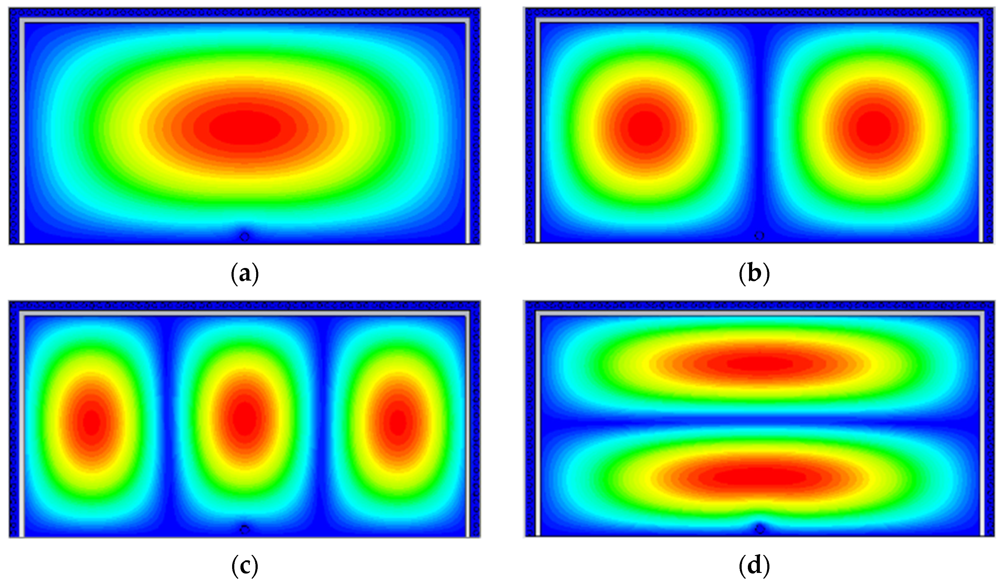
Figure 3.
Vector H-field distribution of four different modes: (a) TE110 mode, (b) TE210 mode, (c) TE310 mode, and (d) TE120 mode.
Figure 3.
Vector H-field distribution of four different modes: (a) TE110 mode, (b) TE210 mode, (c) TE310 mode, and (d) TE120 mode.
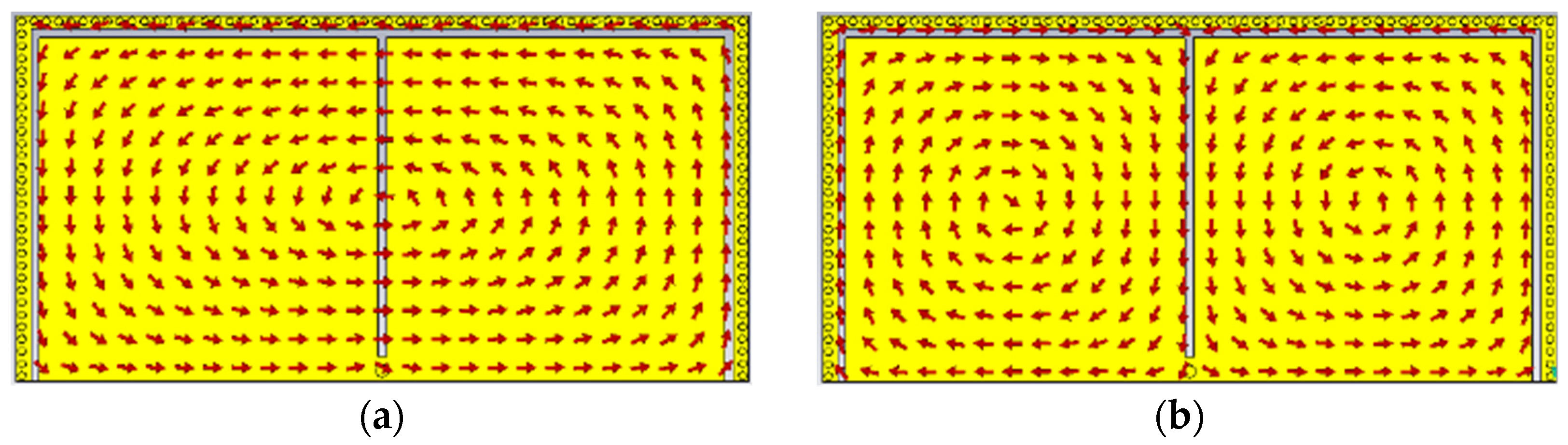

Figure 4.
Variation of resonant frequencies for different modes.
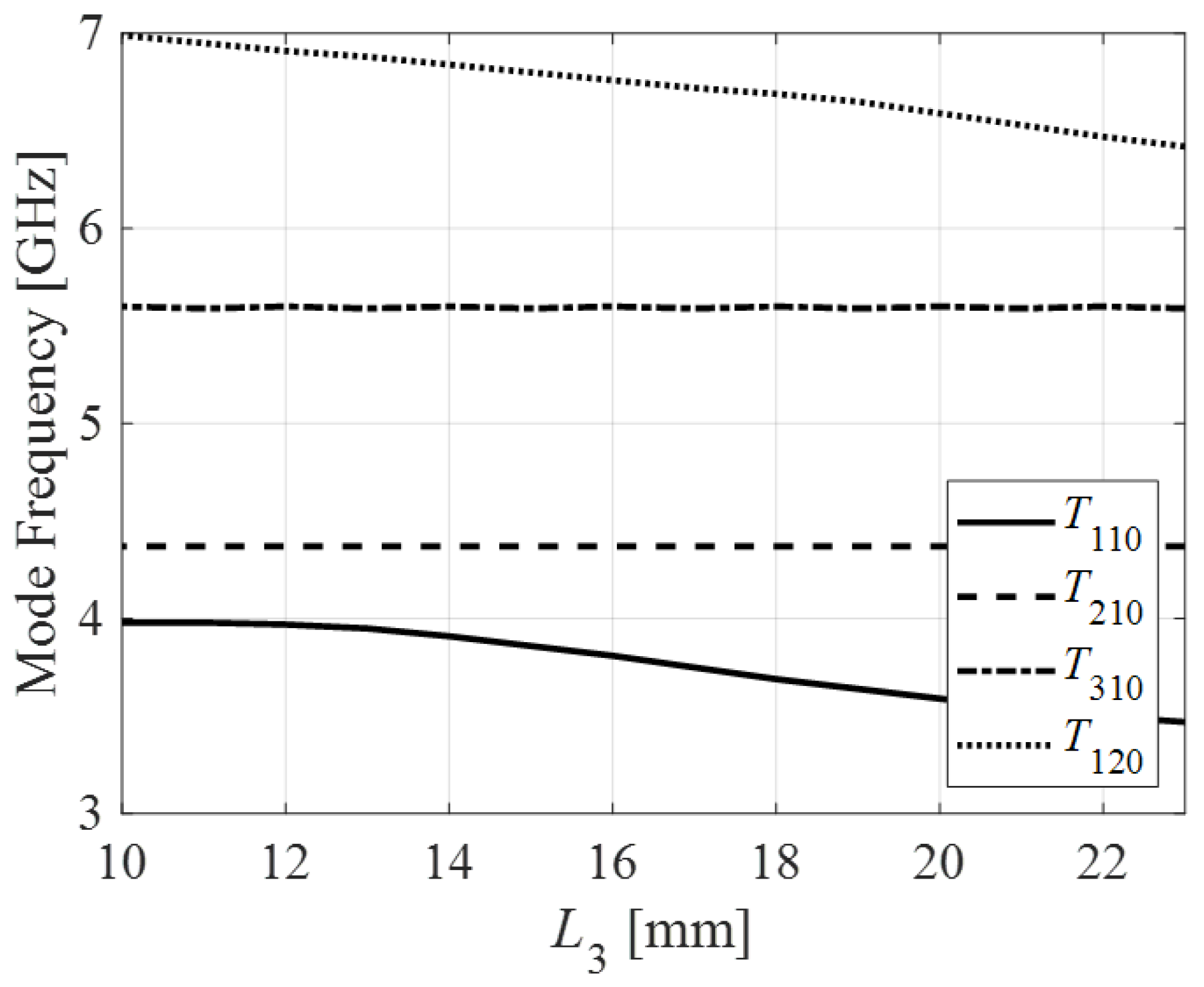
Figure 5.
Variation of coupling coefficient as a function of W3.
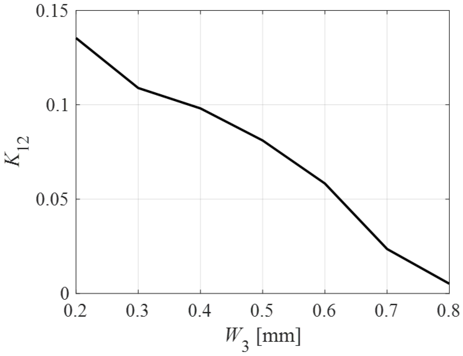
Figure 6.
Dual-mode BPF S-parameters estimated using coupling matrix and EM simulation.
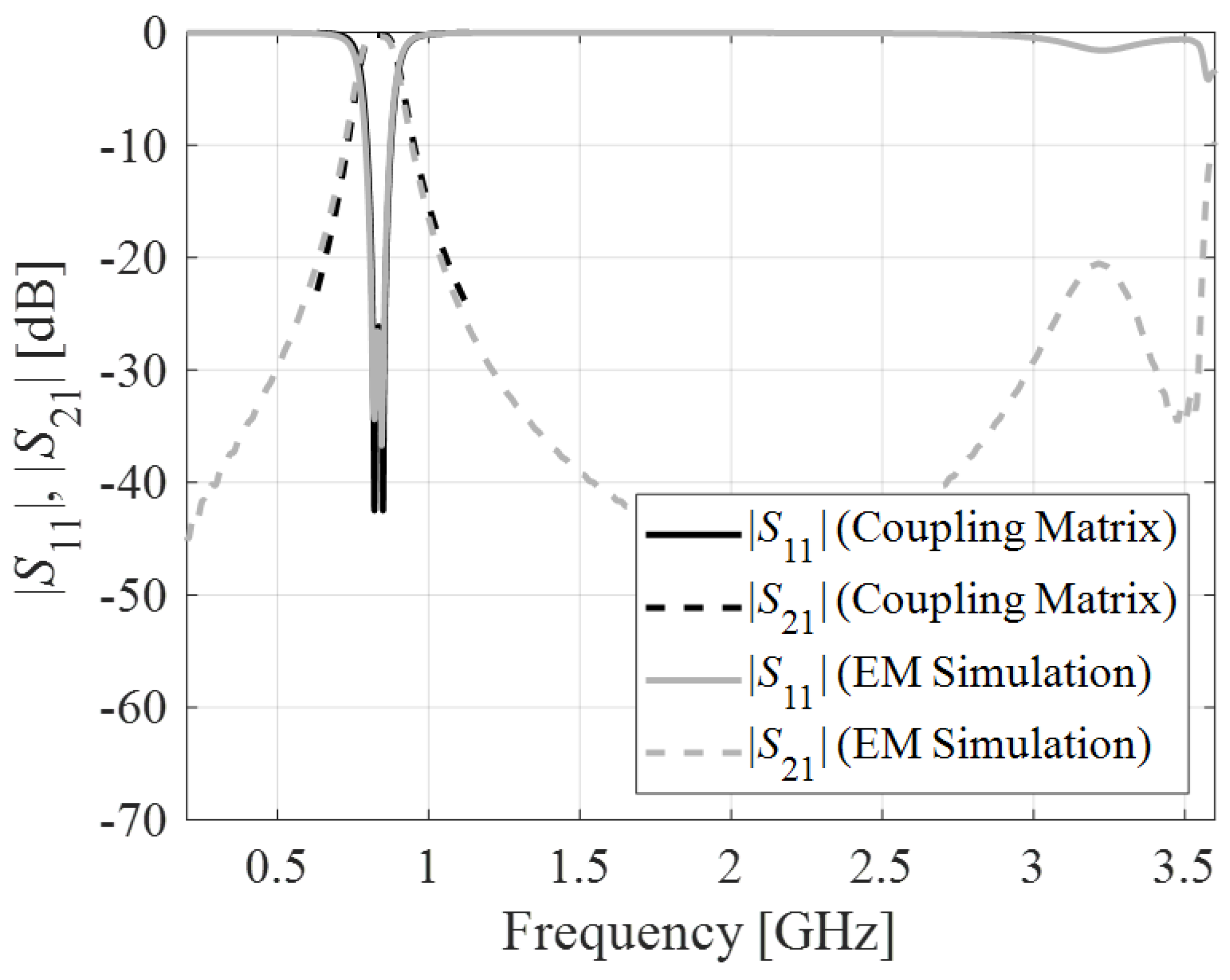
Figure 7.
Estimated losses of the proposed second-order BPF.

Figure 8.
Various insertion losses with an increase in operating frequency for various values of Ls.
Figure 8.
Various insertion losses with an increase in operating frequency for various values of Ls.
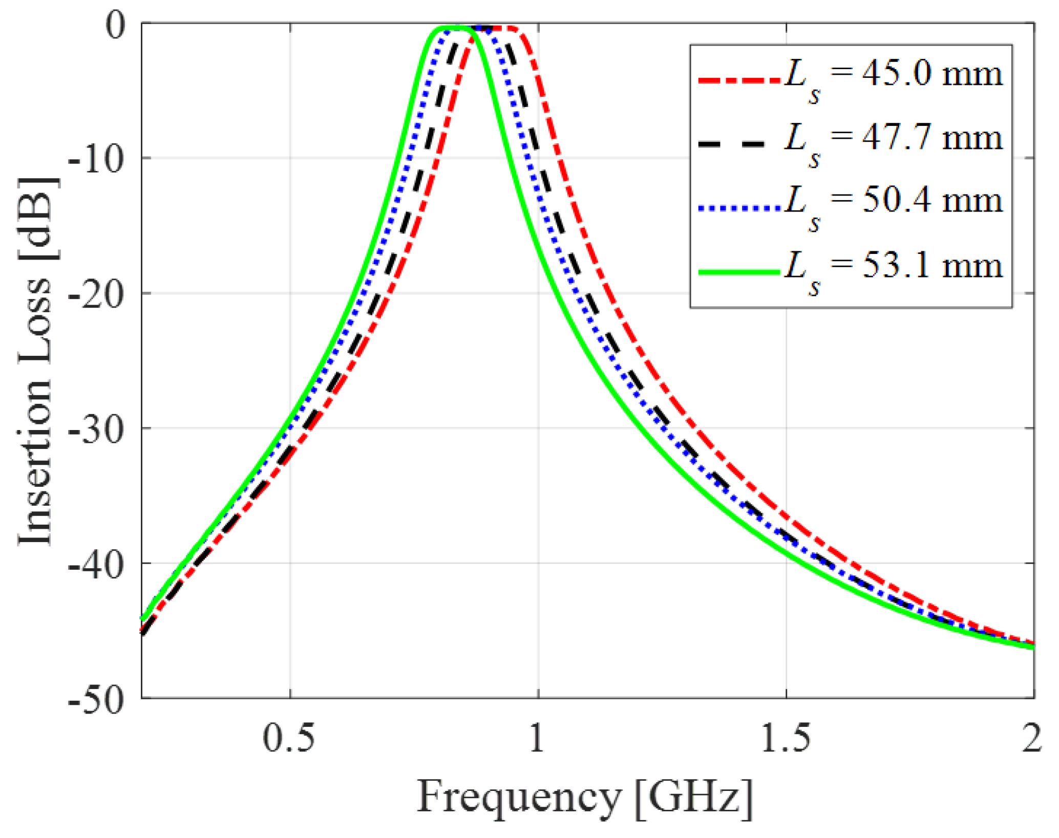
Figure 9.
Analogous circuit model of the proposed HMSIW-based BPF. The electrical parameters are Lmv = 15.0061 nH, L01 = 4.3357 nH, C01 = 0.02 pF, L02 = 16.8144 nH, C02 = 0.02 pF, Lor = 2.5092 nH, and Cor = 19.2436 pF.
Figure 9.
Analogous circuit model of the proposed HMSIW-based BPF. The electrical parameters are Lmv = 15.0061 nH, L01 = 4.3357 nH, C01 = 0.02 pF, L02 = 16.8144 nH, C02 = 0.02 pF, Lor = 2.5092 nH, and Cor = 19.2436 pF.
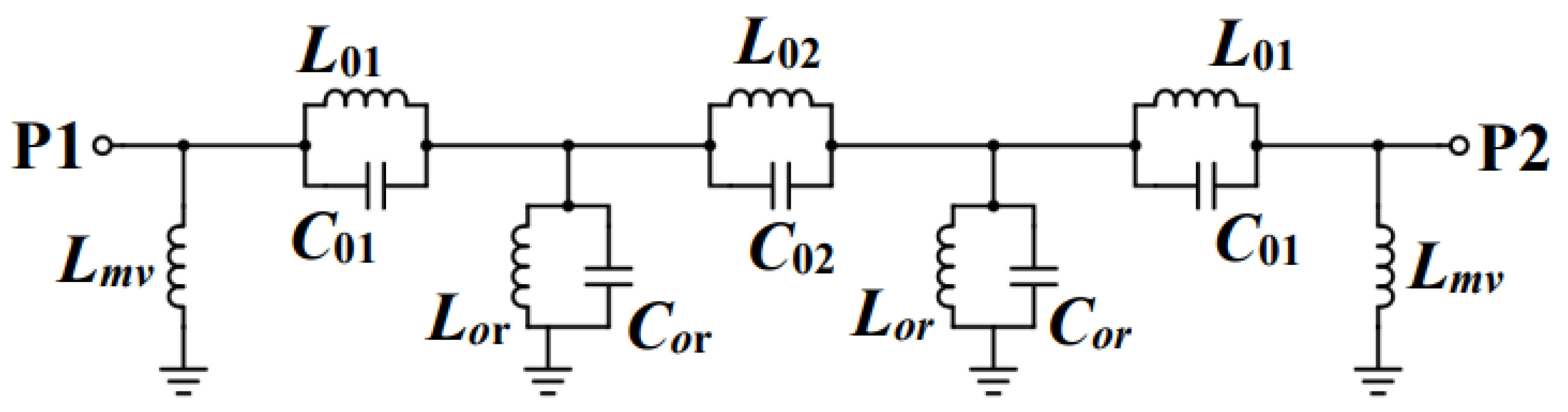
Figure 10.
Circuit and EM simulation S-parameters of the proposed second-order BPF.
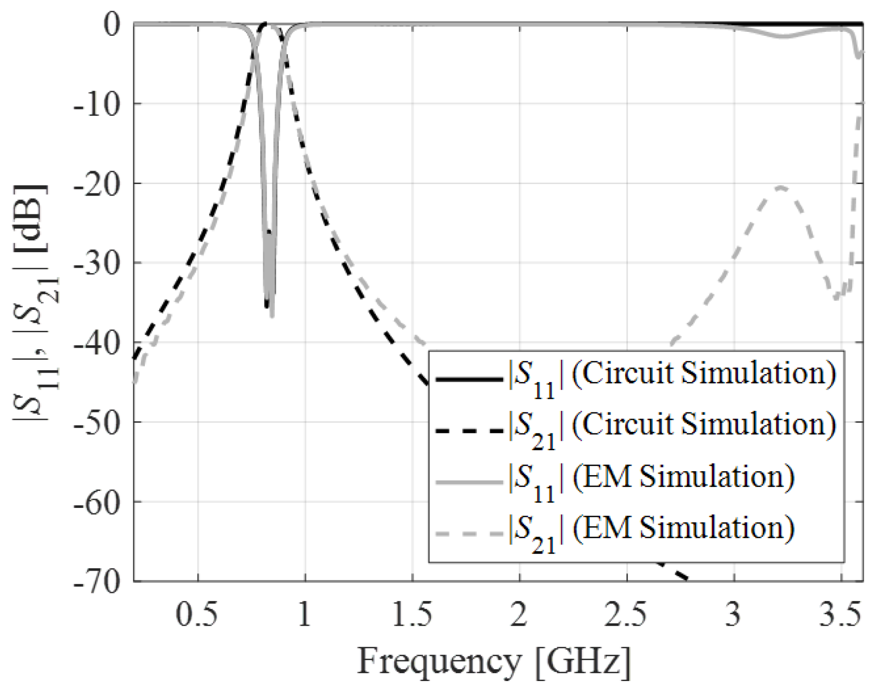
Figure 11.
Experimental validation of the proposed filter: (a) BPF prototype and (b) measurement setup.
Figure 11.
Experimental validation of the proposed filter: (a) BPF prototype and (b) measurement setup.

Figure 12.
EM-simulated and measured S-parameters of the proposed BPF.


Table 1.
Insertion loss with an increase in operating frequency.
| Ls (mm) | f0 (GHz) | IL (dB) |
|---|---|---|
| 53.1 | 0.839 | 0.362 |
| 50.4 | 0.86 | 0.367 |
| 47.7 | 0.891 | 0.364 |
| 45 | 0.938 | 0.37 |
Table 2.
A comparison of the proposed BPF with the state-of-the-art BPFs.
| Ref | fc (GHz) | FBW (%) | IL (dB) | N | Upper Stopband | Size (λg2) | SF (%) |
|---|---|---|---|---|---|---|---|
| [4] | 8 | 20 | 0.7 | 2 | 14 [email protected] f0 | 0.176 | 32.9 $ |
| [5] | 8 | 3.51 | 2.15 | 3 | 20 [email protected] f0 | 0.804 | 28.53 |
| [6] | 7.55 | 1.84 | 3.22 | 3 | 20 [email protected] f0 | 1.61 | 22.2 |
| [7] | 4 | 16 | 1.02 | 3 | 15 [email protected] f0 | 0.0625 | 40.9 |
| [8] | 5 | 6.6 | 0.9 | 3 | 30 [email protected] f0 | NR | 30.2 |
| [9] | 10.8 | 16.5 | 1.5 | 3 | 20 [email protected] f0 | 1.09 | 62.2 |
| [12] | 8 | 11 | 0.9 | 3 | 23 [email protected] f0 | 0.147 | 25.3 |
| [14] | 5.22 | - | 1.62 | 4 | 20 [email protected] f0 | - | 51.47 |
| [15] | 10 | 5.3 | 2.4 | 4 | 30 [email protected] f0 | 1.75 | 36.6 |
| [16] | 10.01 | 3.98 | 1.52 | 4 | 20 [email protected] f0 | 1.978 | 38.3 |
| [17] | 10 | 3.3 | 1.55 | 4 | 30 [email protected] f0 | 2 | 49.27 |
| [18] | 10.11 | 11.7 | 1.22 | 4 | 20 [email protected] f0 | 0.5 | 41.9 |
| [19] | 3.25 | 4.62 | 2.5 | 2 | NA | 0.051 | 19.85 |
| [21] | 1 | 12 | 0.83 | 2 | 20 [email protected] f0 | 0.038 | 30.6 $ |
| [22] | 4.51 | 26 | 0.57 | 4 | 20 [email protected] f0 | 0.159 | 43.7 |
| [23] | 10.6 | 17.77 | 2.61 | 3 | 20 [email protected] f0 | 0.016 | 26.45 $ |
| This work | 0.835 | 15.8 | 0.41 | 2 | 20 [email protected] f0 | 0.028 | 32.51 $ |
FBW: three dB fractional bandwidth; IL: insertion loss; N: order; fc: center frequency; SF: selectivity factor; and $: based on 20 dB bandwidth.
Disclaimer/Publisher’s Note: The statements, opinions and data contained in all publications are solely those of the individual author(s) and contributor(s) and not of MDPI and/or the editor(s). MDPI and/or the editor(s) disclaim responsibility for any injury to people or property resulting from any ideas, methods, instructions or products referred to in the content. |
© 2023 by the authors. Licensee MDPI, Basel, Switzerland. This article is an open access article distributed under the terms and conditions of the Creative Commons Attribution (CC BY) license (https://creativecommons.org/licenses/by/4.0/).
Share and Cite
MDPI and ACS Style
Barik, R.K.; Koziel, S.; Pietrenko-Dabrowska, A. Broad Stopband, Low-Loss, and Ultra-Compact Dual-Mode Bandpass Filter Based on HMSIRC. Electronics 2023, 12, 2831. https://doi.org/10.3390/electronics12132831
AMA Style
Barik RK, Koziel S, Pietrenko-Dabrowska A. Broad Stopband, Low-Loss, and Ultra-Compact Dual-Mode Bandpass Filter Based on HMSIRC. Electronics. 2023; 12(13):2831. https://doi.org/10.3390/electronics12132831
Chicago/Turabian StyleBarik, Rusan Kumar, Slawomir Koziel, and Anna Pietrenko-Dabrowska. 2023. "Broad Stopband, Low-Loss, and Ultra-Compact Dual-Mode Bandpass Filter Based on HMSIRC" Electronics 12, no. 13: 2831. https://doi.org/10.3390/electronics12132831
Note that from the first issue of 2016, this journal uses article numbers instead of page numbers. See further details here.