
Sensing and Secure NOMA-Assisted mMTC Wireless Networks
by
 , and
, and
Urvashi Chaudhary
1,
Mohammad Furqan Ali
1 ,
,
Samikkannu Rajkumar
2 and
Dushantha Nalin K. Jayakody
1,2,3,*
1
School of Computer Science and Robotics, National Research Tomsk Polytechnic University, 634034 Tomsk, Russia
2
Centre for Telecommunication Research, School of Engineering, Sri Lanka Technological Campus, Padukka 10500, Sri Lanka
3
Centro de Investigaçä em Tecnologias-Autónoma TechLab, Universidade Autónoma de Lisboa, 1169-023 Lisboa, Portugal
*
Author to whom correspondence should be addressed.
Electronics 2023, 12(10), 2322; https://doi.org/10.3390/electronics12102322
Submission received: 4 November 2022
/
Revised: 2 December 2022
/
Accepted: 2 December 2022
/
Published: 21 May 2023
(This article belongs to the Special Issue Physical Layer Security in Future IoT Networks: Theories, Technologies, and Applications)
Abstract
:Throughout this study, a novel network model for massive machine-type communications (mMTC) is proposed using a compressive sensing (CS) algorithm and a non-orthogonal multiple access (NOMA) scheme. Further, physical-layer security (PLS) is applied in this network to provide secure communication. We first assume that all the legitimate nodes operate in full-duplex mode; then, an artificial noise (AN) signal is emitted while receiving the signal from the head node to confuse eavesdroppers (Eve). A convex optimization tool is used to detect the active number of nodes in the proposed network using a sparsity-aware maximum a posteriori (S-MAP) detection algorithm. The sensing-aided secrecy sum rate of the proposed network is analyzed and compared with the sum rate of the network without sensing, and the closed-form expression of the secrecy outage probability of the proposed mMTC network is derived. Finally, our numerical results demonstrate the impact of an active sensing algorithm in the proposed mMTC network; improvement in the secrecy outage of the proposed network is achieved through increasing the distance of the Eve node.
1. Introduction
The perspective of fifth generation and beyond (5GB) networking technology, including the sixth generation (6G), is expected to fulfill the numerous shortcomings of existing wireless networks by providing mass connection of nodes simultaneously, enhancement of reliability, and reducing network unavailability [1]. Most significantly, 6G is anticipated to provide ultra-reliable communication, ultra-low latency, and wide accessibility. Recently, smart devices have enabled next-generation wireless networks to play an ample role in real-time data encryption/decryption, leading to further heavy data traffic flow. Therefore, the current wireless networks may not be completely supported by the available technologies. To cope with the related issues, the 6G wireless network is proposed with new spectrum and energy-efficient transmission techniques. However, multiple access scheme (MAS) collaborate in the development of large scale wireless networks [2]. Additionally, a potential MAS can be integrated as a non-orthogonal multiple access (NOMA) scheme. It is noteworthy that NOMA has been proposed for its high spectrum efficiency along with massive connectivity in 5G wireless networks. It serves the multiple connectivity of users within the same network with respect to time and frequency variation. At a glance, power-domain NOMA (PD-NOMA) is a subclass of NOMA schemes which allows users to convey their information using varying power levels and in superposition coding terminology. Similarly, the successive interference cancellation (SIC) technique is applied at the receiver end for decoding of signals in NOMA-based communications networks.
Indeed, power distribution scheduling enhances the performance of a full NOMA-based wireless network [3,4]. Moreover, the base station (BS) transmits all users’ information through the same channel in a NOMA scenario. Further, the position of each user is identified by the effective channel gain in the queue. NOMA facilitates and assign a higher fraction of power to the users having weak signal strength [5]. Cooperative communication is an efficient way to enhance capacity while improving transmission reliability and spatial diversity. Users or dedicated relays cooperate among themselves to improve the transmission reliability of the system [6]. Further, to improve the spectrum efficiency and system throughput, the authors in [7] have investigated an amplify-and-forward (AF) relay-based NOMA network by implying Nakagami-m fading channels. Most recently, similar work has been proposed in [8], where the authors use a physical layer network coding (PLNC)-based NOMA wireless network to improve spectral and temporal efficiency.
Intermittent and sporadic user activity in wireless communication is a major characteristic of massive machine-type communications (mMTC) networks, known as machine-to-machine (M2M) communication. Originally, the concept of an mMTC was proposed by the International Telecommunications Union (ITU) to provide large-scale connectivity services through cellular networks for massive machine-type communications devices. As part of new radio technology, the deployment of NOMA in mMTC has attracted the attention of industrial communities [9]. Further, mMTC has been viewed as a promising technology for innovation with numerous smart sensors immersed in machine learning techniques and intelligence [10]. When an mMTC operates with a large number of devices, it mainly faces the issues of scalability, modeling, coverage, and congestion. Due to massive signaling overhead, NOMA schemes have been used to overcome such problems and improve massive access.
In an mMTC system, a limited number of users are expected to transmit short data packets to the Access Point (AP); in each time slot, a large number of user devices are registered to an AP [11]. To obtain massive access, an mMTC network is mainly focused on the uplink NOMA systems, in which a small number of active users can randomly transmit data at any time slot without any trembling process [12]. Therefore, the multiple distribution of active users inspires the formulation of the multi-user detection problem under the compressive sensing (CS) framework. The CS is a novel sampling paradigm used to reconstruct a sparse physical signal that samples signals in a much more efficient way than the established Nyquist sampling theorem [13]. As a result, the CS is a more suitable method for detecting the active nodes in a particular region of an mMTC wireless network.
In contrast, the field of physical layer security (PLS) has been introduced to achieve a secure communication platform, which implies critical issues over wireless networks in different scenarios [14]. The PLS was proposed by Wyner to improve the security of the network as an alternative approach to the cryptographic techniques [15]. The advantage of PLS is that it protects information by exploiting intrinsic characteristics of the communications medium, thereby promising wireless security [16]. In existing works, authors [17,18] have considered the PLS for NOMA-based networks for single-antenna and multiple-antenna networks under the stochastic geometry concept. PLS can be applicable considering the physical layer properties of the communication system, such as noise, interference, and the time-varying property of fading channels [19]. Recently, a NOMA-based uplink mMTC network model was developed in [20] and its performance was studied. The basic idea behind PLS is to reduce the the signal characteristics of the intended receiver for an eavesdropper (hereinafter referred to as Eve) [21]. Due to the broadcast nature of wireless networks, transmission between authorised users can easily be overheard by Eve for interception. It is challenging to deploy an active Eve or multiple Eves within heterogeneous networks [22]. A comprehensive review of PLS techniques for internet of things (IoTs) applications is discussed in [23], followed by a survey of existing PLS techniques and the characteristics of IoT.
1.1. Motivation
Motivated by the existing research, here we propose a novel mMTC network with a view to 6G networking system. As the existing research works have demonstrated that many network nodes are in idle condition, it is necessary to develop a low-power-consumption wireless network that can provide the high capacity needed for massive connectivity. Throughout this study, we propose a system model for massive connectivity within the 6G wireless networking approach. More specifically, we focus on constructing a suitable algorithm for sensing the active nodes in the given region of the mMTC networks, which can greatly improve overall network performance. In fact, mMTC is one of the major requirements of a 6G wireless network that can fulfill real-time data streaming applications in fields such as health care, industrial monitoring, traffic control, agriculture, etc. In another direction, providing secure communication in the mMTC networks, such as for command message passing in military contexts or control messages in industry, is another major concern. Therefore, in this a new network model for mMTC a network is proposed using PLS and CS algorithms to enhance sensing and secure communications.
1.2. Contributions
The main contributions of this paper can be summarized as follows:
- Throughout this study, we propose novel massive connectivity of machine-type communication system towards the 6G networking system utilizing the PLS.
- In an mMTC, the detection of inactive/active nodes is challenging; therefore, a new approach for detection is investigated in this study using the CS algorithm.
- Throughout this study, analytical expressions are provided and then verified by simulation results, and the end-to-end (E2E) performance metrics of the proposed system, such as secrecy and outage probability, are derived in detail.
The rest of the paper is organized as follows. In Section 2, the system model of the proposed network is discussed and the CS algorithm is explained. In Section 3, the performance aspects of the proposed mMTC network, such as the sensing-aided sum rate and secrecy outage probability, are explained. In Section 4, our numerical analysis is discussed, and lastly we provide concluding remarks in Section 5.
2. System Model
In the proposed system model, we consider an mMTC network in which number of nodes are distributed randomly in the given region, as in Figure 1. Among the nodes, only one node acts as a head node (the blue-colored node), and serves the remaining N nodes using a NOMA scheme. The geometrical model of the region is formulated as a circular region, and based on the distances of the nodes, a set of nodes is located in the inner circular region (near users) and the remaining nodes distributed in the outer circular region (far users). Because the number of nodes in a particular region is dynamic, it can be modeled as an homogeneous Poisson point process (HPPP) [24]. In this mMTC model, the radii of the inner and outer circular regions are denoted by and , respectively. In practical mMTC networks, there is a security issue that frequently arises due to unauthorized nodes, which are indicated as eavesdroppers (Eves) in this proposed model. An Eve node wants to trace confidential messages from the legitimate nodes. Hence, all nodes are designed in full-duplex mode, such that they always generate artificial noise (AN) while receiving message from the head node, which is intended to confuse any Eve nodes.
In existing mMTC networks, several of the nodes are in inactive condition due to certain practical issues. In such a scenario, random allocation of power to all users is not a favorable approach. Therefore, it is necessary to develop a suitable algorithm to sense all the active nodes in mMTC networks in order to enhance network performance. In this work, a single measurement vector-based CS algorithm [25] is used to sense active nodes.
2.1. Active Nodes Sensing
We assume that each node in the mMTC network is active with a probability of and that the head node identifies the activity of each node by simply checking whether or not a particular node has any useful information. Further, it is assumed that at any time only few nodes are active and that the head node receive the signals from both the active and inactive nodes; hence, the network can be modeled as a sparse vector. Thus, the CS algorithm represents a suitable method for detecting the sparse signals. The node () transmits its message frame to the head node using binary phase shift keying (BPSK) modulation scheme, which is denoted as . Each frame consists of M BPSK symbols . Note that the proposed mMTC network is developed for low power and low data rate communications, such as e-healthcare, industrial automation, home automation, etc.; hence, BPSK modulation is sufficient to transmit control messages. The messages received from all N nodes can be represented as an sparse vector, as provided by , where if the node is inactive. Therefore, the received signal at the head node is
where is a measurement matrix designed using channel matrix in which , where is the number of channel taps in the node, is the relative delay and spreading matrix with spreading factor q [26] of the node, and z is additive white Gaussian noise (AWGN) with zero mean and variance . Using the sparsity-aware maximum a posteriori (S-MAP) detection algorithm [25], the active nodes are identified as follows:
where , is the active devices probability, is the estimated sparse vector, and its sum of non-zero elements provides the total number of active nodes, which is denoted as . By sensing the indices of the non-zero elements of the sparse vector, the head node allocates power to all the active nodes according to the NOMA scheme, thereby enhancing the performance of the mMTC network.
To improve active device detection in mMTC networks, it is necessary to analyze the active device detection error at the receiver. The normalized average mean square error of active device detection can be calculated as follows:
where is the number of iterations. It is noteworthy that active device detection mainly depends on parameters such as the percentage of active devices , spreading factor q, and signal-to-noise ratio (SNR). In addition, the normalized average mean square error is helpful in analysing device detection via the S-MAP algorithm; device detection improvement can be achieved by increasing the SNR values, which is discussed in detail in Section 4.
2.2. Sensing-Aided Downlink Transmission
By applying the S-MAP algorithm, the head node is able to determine the status of the nodes. Thus, the head node allocates power only to active nodes based on the channel conditions. The channel gains are arranged in ascending order (), and power allocation is performed correspondingly (). Note that an mMTC networks contains a large number of nodes; hence, allocating power after dividing the nodes into a number of groups is preferable, and is the approach considered in the rest of this work. Using the NOMA scheme, the head node superimposes all active node signals as , where is the head node’s transmitting power. Here, the power allocation coefficient must satisfy the condition and = 1.
For downlink transmission, the head node transmits the NOMA signal to all the nodes simultaneously. Because each node adopts full-duplex mode, it can emit the AN signal while receiving the signal from the head node. In addition, each node suffers from loop interference (LI) due to full-duplex operation. Here, let the node act as a near node, and let the node act as a far node, . Because the transmit signals are in the form of frames, and because each frame consists of M symbols, the NOMA symbol can be written as . Therefore, the received symbol at the near node can be written as
where is the channel coefficient between the head node and near node and subscript h denote the head node. Furthermore, a channel modeled using small- and large-scale fading and its channel gain follow the exponential distribution, with mean 0 and variance . Additionally, the parameters are defined as the follows: the distance from the head node to the near node is , the path loss exponent is , the channel coefficient of the LI is , which is exponentially distributed with mean 0 and variance , and the AWGN is , and is defined using . The received signal from the far node can be calculated in a similar way.
At the same time, Eve traces the signal from the head node; the signal received from Eve can be expressed as
where is the channel coefficient between the head node and Eve and is the AN signal, which is generated using a pseudo-noise (PN) sequence. Its channel gain follows the exponential distribution, with mean 0 and variance . However, here is the distance from the head node to Eve, is the channel coefficient between the near node and Eve, and is the AWGN at Eve. Note that the AN signal is received from the far node with channel a coefficient of .
3. Coverage, Capacity, and Outage Analysis of Proposed mMTC
3.1. Uplink Coverage Probability of the mMTC
The proposed mMTC network is designed for short-distance communications; hence, the propagation model in the uplink is designed using a stretched exponential path loss (SEPL) model [27]. In this SEPL model, multipath fading is modeled by distribution, where is the average multiplicative attenuation, is the integer constant, and the transmit power attenuation is modeled as , where r is the distance, is the number of obstructions in the path, and is the model parameter. Further, the maximum power needed at a distance to avoid outage of an mMTC node is . Therefore, the cumulative distribution function (CDF) of this channel is modeled by
where is the Gamma function and is the lower incomplete gamma function. The signal-to-interference plus noise (SINR) of the mMTC device at the base station (BS) is expressed as
The uplink coverage probability of the proposed mMTC network is provided by
In contrast, using and it can be simplified as
Further, (9) can be simplified to obtain (10):
where and Here, let and ; then, the coverage probability of the proposed mMTC network can be simplified as follows:
Expression (11) is a complex equation; therefore, by splitting the exponential term into two parts it becomes
By taking , the coverage probability expression can be simplified using the Laplace transform; thus, can be written as
where is the Laplace transform of the interference term. For further integration, (13) can be written as follows:
By implying the exponential term, (14) can be modifies as follows:
With the Laplace transformation using [28], the of the coverage probability can be simplified as follows:
where is the active device probability, is the increasing density of active devices, and is the number of resource blocks. By applying the Laplace transform to , we obtain the expression in exponential form, as follows:
Let and be the coverage probability, which is integrated as follows:
Setting and , the coverage probability of the proposed mMTC networks is determined as follows:
3.2. Sensing-Aided Sum Rate
Because there are N nodes and each node transmits M symbols, the total number of symbols is MN. In the downlink, each node receives a NOMA signal, which consist of MN symbols, and decodes it on a symbol-by-symbol basis using an SIC operation. In downlink NOMA, the near node applies SIC and the far node directly decodes its message while treating the near node message as interference. The near node first decodes the far node’s message, then it removes the decoded far node message after decoding its own message. The signal-to-interference plus noise ratio (SINR) of a far node, for decoding a near node, in the presence of LI can be written as
where is the LI power. For the case of two nodes, this can be further simplified as
After omitting the far node message, the near node decodes its own message as follows:
Similarly, the SINR of the far node can be written as
Eve receive NOMA messages from the legitimate nodes as well; therefore, the SINR of the Eve node can be written as
Using the above SINR expressions, the secrecy sum rate of the proposed mMTC network can be calculated. The secrecy rate of the near node can be expressed as
where indicates the , and are the near node and far node capacities, respectively, and and are the near Eve node and far Eve node capacities, respectively. The mathematical expressions for the the secrecy rates and are provided by
Similarly, the rates of the and are written as
Without sensing the active nodes, the total transmit power of the head node is shared among N legitimate nodes using the NOMA scheme . Thus, the performance of the mMTC network falls due to power being allocated to inactive nodes. However, when using the sensing algorithm, the head node shares power only among active nodes , which significantly improves the secrecy sum rate of the proposed mMTC network.
Finally, the secrecy sum rate of the proposed NOMA-based mMTC network can be expressed as
3.3. Secrecy Outage Probability
In this section, the secrecy outage probability of the near node is discussed. However, it is easy to extend this analysis to the far node secrecy outage. The secrecy outage probability of the near node can be written as
where R is the threshold data rate. Substituting and , the secrecy outage becomes
By rearranging (18), the secrecy outage probability of the near node is
Here, and can be modelled as random variables X and Y, allowing the secrecy outage to be simplified as follows:
where and denote the probability density function (PDF) of and , respectively. After integration and simplification, the secrecy outage probability of the near node can determined as
where is the exponential integral function, ,
, , , ,
and is the zero point of .
Proof.
See Appendix A. □
3.4. Outage Probability without Eve
Without Eve, the outage probability of the far node can be expressed as
Let , , then the outage probability of the far node can be simplified as [8].
Let ; then, it becomes
Because x follows an exponential distribution, the outage probability of the far node without Eve can be determined as follows:
4. Results and Discussion
In this section, the secrecy sum rate and secrecy outage probability of the proposed NOMA-based mMTC network is discussed. In addition, active node detection in the mMTC network using the CS algorithm is described, as well as the use of the convex optimization toolbox ‘’ to estimate the sparsity of active nodes. Matlab software was used for all the simulations of performance metrics, including the coverage probability, sum rate, outage probability, and secrecy outage probability of the proposed mMTC network, and the legitimate node channel variance was fixed to 1 for all the simulations. The detailed simulation parameters are listed in Table 1.
The normalized average mean square error of active device detection is shown in Figure 2a. A convex optimization tool is used to detect the active devices in the proposed mMTC network; the active devices are then modeled as a sparse vector. From this figure, it can be observed that the mean square error of active device detection increases when the percentage of active devices increases. Further, the performance of active device detection improves when the SNR values increase. Figure 2b shows the comparison of the total number of active devices detected in the proposed mMTC wireless networks. In this figure, it can be noted that even though the average mean square error increases with the percentage of active devices, the total number of active devices detected increases as well.
Figure 3a shows the uplink coverage probability of the proposed mMTC wireless network. In this simulation, the following parameters are considered: active device probability is varied as 0.12, 0.13, and 0.14, SNR = −130 dBW, noise variance = −151.45 dBW, data rate R = 2 b/s/Hz, , increasing density of active devices , number of resource blocks , path loss model parameter . From this figure, it can be observed that the coverage probability of the proposed networked is reduced when increasing the active device probability. Therefore, better coverage of the proposed mMTC network can be achieved by increasing the active device probability. Similarly, the coverage probability of the proposed mMTC network is analyzed for various values. In this figure, coverage of the proposed network is improved when increasing the number of resource blocks.
Figure 4a shows the sum rate of the proposed NOMA-based mMTC network without Eve. In this simulation, the number of legitimate nodes is 40 and the LI power is −10 dBW. Active node detection is performed using the convex optimization toolbox. The sum rate of the proposed network is compared with the sensing-aided sum rate and perfect SIC-based sum rate. It can be observed that the active sensing algorithm is not effective when the number of nodes is low. However, the proposed mMTC network achieves significant improvement thanks to the active sensing algorithm as the number of nodes increases. Furthermore, it can be observed that, with perfect SIC and the active sensing approach, the sum rate of the proposed network is even better than the sum rate with sensing. Therefore, it can be concluded that the active node detecting approach plays a vital role in the mMTC network, enhancing overall network performance.
The secrecy sum rate of the proposed NOMA-based mMTC network is shown in Figure 4b. The number of legitimate nodes is 40, and AN and LI power are considered as −10 dBW. The secrecy sum rate is estimated by taking the sum rate difference between legitimate nodes and Eve nodes. The sum rate is compared with and without the sensing algorithm and perfect SIC. From this figure, it can be noted that the active sensing algorithm is effective in the proposed mMTC network even with a lower number of nodes. Furthermore, the sum rate is significantly increased when the number of nodes in the proposed network increases. However, with the presence of Eve, the sum rate of the proposed mMTC network is low compared to the network without Eve. For instance, with 30 nodes the secrecy sum rate with sensing is around 5 b/s/Hz, whereas without Eve the sum rate is 13 b/s/Hz. This makes the effect of the Eve node in the mMTC network very evident; hence, designers ought to change the configuration of the network to obtain high quality of service even when Eve nodes ar present.
Figure 5a shows the outage probability of the proposed mMTC network. In this simulation, the presence of Eve is omitted; hence, LI and AN power are not considered, and other parameters, such as the distance of the far node = 6 m, distance of the near node = 4 m, and path loss exponent are used. The analytical results are validated using the presented simulation results. The outage probability of the far node and near node are compared using the rates R = 1 b/s/Hz and R = 0.5 b/s/Hz. At the target outage level of , the near node needs 25 dBW SNR, whereas far node requires 28 dBW SNR. For a threshold data rate of R = 0.5 b/s/Hz, this indicates that an additional 3 dBW SNR is needed for the far node.
The secrecy outage performance of the proposed mMTC network is shown in Figure 5b. In this simulation, the following parameters are used: distance of the near node = 2 m, distance from near node to Eve node = 3 m, Gauss–Lagurre Quadrature K = 10, path loss exponent , threshold data rate R = 1 b/s/Hz, and LI and AN power −10 dBW. From this figure, it can be observed that the outage performance of the proposed mMTC network is degraded due to the presence of LI and AN power. When the Eve node is near the head node, it receives a strong signal from the head node, degrading the network’s outage performance. Therefore, it is better to always keep Eve nodes a certain distance away from the head node to ensure better network performance.
5. Conclusions
In this study, a novel network model for an mMTC network is proposed using a NOMA scheme and the CS algorithm. Additionally, the PLS scheme is applied in this network to provide secure communication. Active node detection is performed in the proposed network using the S-MAP algorithm to improve the secrecy sum rate. Using the Laplace’ transform, the mathematical expression for the coverage probability of the proposed network is derived, along with a closed-form expression of the secrecy outage probability of the proposed mMTC network. Finally, our numerical results demonstrate that the active device sensing algorithm plays a vital role in the proposed mMTC network by enhancing the efficient utilization of resources. Finally, the secrecy outage performance ensures secure communication while maintaining the QoS of the active nodes in the network.
Author Contributions
Conceptualization, U.C., S.R.; methodology, U.C., S.R., M.F.A.; validation, U.C., S.R., M.F.A.; formal analysis, U.C., S.R., D.N.K.J.; writing—original draft preparation, U.C., S.R., M.F.A.; writing—review and editing, S.R., M.F.A., D.N.K.J.; visualization, D.N.K.J.; funding acquisition, D.N.K.J. All authors have read and agreed to the published version of the manuscript.
Funding
This work was funded, in part, by the CEU-Cooperativa de Ensino Universitário, Portugal and by the framework of Competitiveness Enhancement Program of the National Research Tomsk Polytechnic University, Russia.
Institutional Review Board Statement
Not applicable.
Informed Consent Statement
Not applicable.
Data Availability Statement
This study did not report any data.
Conflicts of Interest
The authors declare no conflict of interest.
Abbreviations
The following abbreviations are used in this study:
| 5Gb | Fifth Generation and beyond |
| 6G | Sixth Generation |
| AN | Artificial Noise |
| AWGN | Additive White Gaussian Noise |
| BPSK | Binary Phase-Shift Keying |
| BS | Base Station |
| CDF | Cumulative Distribution Function |
| CS | Compressive Sensing |
| Eve | Eavesdropper |
| E2E | End-to-End |
| HPPP | Homogeneous Poisson Point Process |
| ITU | International Telecommunications Union |
| LI | Loop Interference |
| mMTC | massive Machine-Type Communications |
| M2M | Machine-to-Machine Communication |
| NOMA | Non-Orthogonal Multiple Access |
| Probability Density Function | |
| PN | Pseudo-Noise |
| PLNC | Physical Layer Network Coding |
| PLS | Physical Layer Security |
| RB | Resource Block |
| S-MAP | Sparsity-aware Maximum A Posteriori |
| SELP | Stretched Exponential Path Loss |
| SC | Superposition Coding |
| SIC | Successive Interference Cancellation |
| SINR | Signal-to-Interference plus Noise Ratio |
| SNR | Signal-to-Noise Ratio |
Appendix A
Because the sets of nodes are distributed randomly in the inner circular region, which can be modeled using HPPP, in (20) we can write as
where is the threshold SNR. Let , ; then, (A1) can be written as
Inside the inner circular regions, all node distances are random in nature; thus, and its PDF can be written as
By applying limits, this can be modified as follows:
Using Gauss–Chebyshev quadrature [29], this can be further simplified as
where and . By substituting (A6) and in (A2), the outage probability of the near user can be computed as
where is the signal-to-noise ratio (SNR) of the head node. Recall that the secrecy outage probability of the near node is
where is the PDF of Eve’s SINR and , and can be determined as follows. First, compute the CDF of Eve; then, the PDF can be computed using the corresponding CDF. The CDF of can be expressed as
Note that . Let , ; then, the above can be rewritten as
Moreover, (A9) can be written in PDF form as
where . After integrating and simplifying, the CDF of the Eve’s SINR can be computed as follows:
where is the interference-to-noise ratio (INR) of the legitimate node. By integrating (A12), the PDF of can be determined as follows:
where , . By substituting (A7) and (A13) into (A8), the secrecy outage probability of the near node is determined as follows:
The above expression in (A13) consists of four terms; hence, the secrecy outage probability can be rewritten as
where . The parameters , , , and are determined as follows:
where .
Using [30], (3.353.3), (3.352.4), and (3.352.4), the Gauss–Laguarre Quadrature, secrecy, and outage probability of the near user can obtained as in (25).
References
- De Alwis, C.; Kalla, A.; Pham, Q.-V.; Kumar, P.; Dev, K.; Hwang, W.-J.; Liyanage, M. Survey on 6G frontiers: Trends, applications, requirements, technologies and future research. IEEE Open J. Commun. Soc. 2021, 2, 836–886. [Google Scholar] [CrossRef]
- Hakeem, S.A.A.; Hussein, H.H.; Kim, H. Vision and research directions of 6G technologies and applications. J. King Saud Univ. Comput. Inf. Sci. 2022, 34, 2419–2442. [Google Scholar]
- Melki, R.; Noura, H.N.; Chehab, A. Physical layer security for NOMA: Limitations, issues, and recommendations. Ann. Telecommun. 2021, 76, 375–397. [Google Scholar] [CrossRef]
- Men, J.; Ge, J.; Zhang, C. Performance Analysis for Downlink Relaying Aided Non-Orthogonal Multiple Access Networks With Imperfect CSI Over Nakagami-m Fading. IEEE Access 2017, 5, 998–1004. [Google Scholar] [CrossRef]
- Islam, S.M.R.; Avazov, N.; Dobre, O.A.; Kwak, K.-S. Power-domain non-orthogonal multiple access (NOMA) in 5G systems: Potentials and challenges. IEEE Commun. Surv. Tut. 2016, 19, 721–742. [Google Scholar] [CrossRef]
- Ding, Z.; Peng, M.; Poor, H.V. Cooperative non-orthogonal multiple access in 5G systems. IEEE Commun. Lett. 2015, 19, 1462–1465. [Google Scholar] [CrossRef]
- Men, J.; Ge, J.; Zhang, C. Performance analysis of nonorthogonal multiple access for relaying networks over Nakagami-m fading channels. IEEE Trans. Veh. Technol. 2016, 66, 1200–1208. [Google Scholar] [CrossRef]
- Rajkumar, S.; Jayakody, D.N.K.; Chang, Z.A. Hybrid NOMA-PLNC Wireless Relay Scheme. In Proceedings of the IEEE 18th Annual Consumer Commun & Networking Conference (CCNC), Las Vegas, NV, USA, 9–12 January 2021. [Google Scholar]
- Arora, K.; Singh, J.; Randhawa, Y.S. A survey on channel coding techniques for 5G wireless networks. Telecommun. Syst. 2020, 73, 637–663. [Google Scholar] [CrossRef]
- Mahmood, N.H.; Alves, H.; López, O.A.; Shehab, M.; Osorio, D.P.M.; Latva-Aho, M. Six Key Features of Machine Type Communication in 6G. In Proceedings of the 2020 2nd 6G Wireless Summit (6G SUMMIT), Levi, Finland, 17–20 March 2020. [Google Scholar]
- Yu, W. On the fundamental limits of massive connectivity. In Proceedings of the 2017 Information Theory and Applications Workshop (ITA), San Diego, CA, USA, 12–17 February 2017. [Google Scholar]
- Hong, J.-P.; Choi, W.; Rao, B.D. Sparsity controlled random multiple access with compressed sensing. IEEE Trans. Wirel. Commun. 2014, 14, 998–1010. [Google Scholar] [CrossRef]
- Du, Y.; Dong, B.; Chen, Z.; Wang, X.; Liu, Z.; Gao, P.; Li, S. Efficient multi-user detection for uplink grant-free NOMA: Prior-information aided adaptive compressive sensing perspective. IEEE J. Sel. Areas Commun. 2017, 35, 2812–2828. [Google Scholar] [CrossRef]
- ElHalawany, B.M.; Wu, K. Physical-Layer Security of NOMA Systems Under Untrusted Users. In Proceedings of the 2018 IEEE Global Communications Conference GLOBECOM, Abu Dhabi, United Arab Emirates, 9–13 December 2018. [Google Scholar]
- Wyner, A.D. The wire-tap channel. Bell Syst. Tech. J. 1975, 54, 1355–1387. [Google Scholar] [CrossRef]
- Wang, D.; Bai, B.; Zhao, W.; Han, Z. A survey of optimization approaches for wireless physical layer security. IEEE Commun. Surv. Tutor. 2018, 21, 1878–1911. [Google Scholar] [CrossRef]
- Liu, Y.; Qin, Z.; Elkashlan, M.; Gao, Y.; Hanzo, L. Enhancing the Physical Layer Security of Non-Orthogonal Multiple Access-NOMA in Large-Scale Networks. IEEE Trans. Wirel. Commun. 2017, 16, 1656–1672. [Google Scholar] [CrossRef]
- Rajkumar, S.; Jayakody, D.N.K.; Alkanhel, R.; Muthanna, A. Physical Layer Security in N-Pair NOMA-PLNC Wireless Networks. IEEE Access 2022, 10, 91356–91371. [Google Scholar] [CrossRef]
- Furqan, H.M.; Hamamreh, J.; Arslan, H. Physical layer security for NOMA: Requirements, merits, challenges, and recommendations. arXiv 2019, arXiv:1905.05064. [Google Scholar]
- Han, S.; Xu, X.; Tao, X.; Zhang, P. Joint power and sub-channel allocation for secure transmission in NOMA-based MMTC networks. IEEE Syst. J. 2019, 13, 2476–2487. [Google Scholar] [CrossRef]
- Singh, P.; Pawar, P.; Trivedi, A. Physical Layer Security Approaches in 5G Wireless Communication Networks. In Proceedings of the 2018 FirstInternational Conference on Secure Cyber Computing and Communication (ICSCCC), Jalandhar, India, 15–17 December 2018. [Google Scholar]
- Wang, W.; Teh, K.C.; Li, K.H.; Luo, S. On the impact of adaptive eavesdroppers in multi-antenna cellular networks. IEEE Trans. Inf. Forensics Secur. 2017, 13, 269–279. [Google Scholar] [CrossRef]
- Sun, L.; Du, Q. A review of physical layer security techniques for Internet of Things: Challenges and solutions. Entropy 2018, 20, 730. [Google Scholar] [CrossRef]
- Gong, C.; Yue, X.; Wang, X.; Dai, X. Enhancing Physical Layer Security With Artificial Noise in Large-Scale NOMA Networks. IEEE Trans. Veh. Technol. 2021, 70, 2349–2361. [Google Scholar] [CrossRef]
- Alam, M.; Zhang, Q. A Survey: Nonorthogonal Multiple Access with Compressed Sensing Multiuser Detection for mMTC. Wirel. Commun. Mob. Comput. 2021, 2021, 8840519. [Google Scholar] [CrossRef]
- Dekorsy, A.; Brueck, S. Is multiuser detection beneficial to mixed service UMTS networks? Int. J. Electron. Commun. 2005, 59, 473–482. [Google Scholar] [CrossRef]
- Liu, Y.; Ding, Z.; Elkashlan, M.; Poor, H.V. Cooperative non-orthogonal multiple access with simultaneous wireless information and power transfer. IEEE J. Sel. Areas Commun. 2016, 34, 938–953. [Google Scholar] [CrossRef]
- Kamel, M.; Hamouda, W.; Youssef, A. Uplink Coverage and Capacity Analysis of mMTC in Ultra-Dense Networks. IEEE Trans. Veh. Technol. 2020, 69, 746–759. [Google Scholar] [CrossRef]
- Hildebrand, F.B. Introduction to Numerical Analysis; Dover: New York, NY, USA, 1987. [Google Scholar]
- Gradshteyn, I.S.; Ryzhik, I.M. Table of Integrals, Series, and Products, 6th ed.; Academic Press: New York, NY, USA, 2000. [Google Scholar]
Figure 1.
The proposed NOMA-assisted mMTC Wireless Networking System model, with active (green) and inactive (block) nodes distributed randomly in the circular region; an Eve node (red) tries to trace the confidential message information, and the blue node acts as the head node.
Figure 1.
The proposed NOMA-assisted mMTC Wireless Networking System model, with active (green) and inactive (block) nodes distributed randomly in the circular region; an Eve node (red) tries to trace the confidential message information, and the blue node acts as the head node.

Figure 2.
(a) Normalized average mean square error of active device detection and (b) active device detection of the proposed mMTC network.
Figure 2.
(a) Normalized average mean square error of active device detection and (b) active device detection of the proposed mMTC network.

Figure 3.
(a) Uplink coverage probability of the proposed mMTC network for various values and (b) uplink coverage probability of the proposed mMTC network for various values.
Figure 3.
(a) Uplink coverage probability of the proposed mMTC network for various values and (b) uplink coverage probability of the proposed mMTC network for various values.
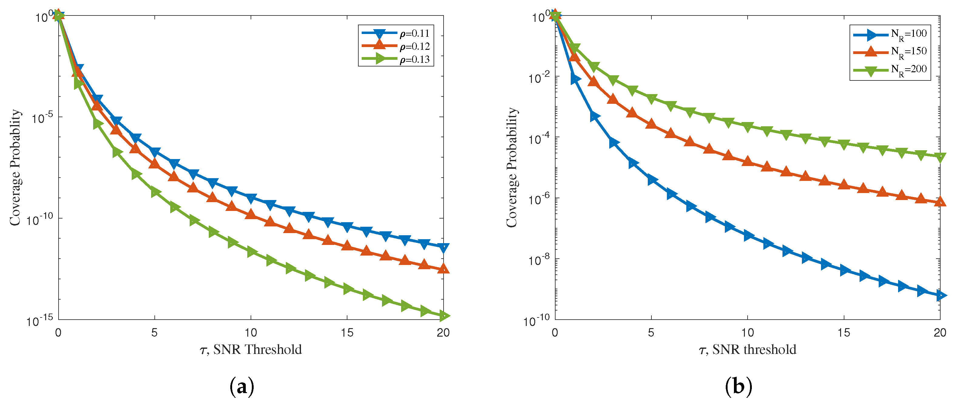
Figure 4.
(a) Sum rate of the proposed NOMA-based mMTC network without Eve and (b) secrecy sum rate of the proposed NOMA-based mMTC network with Eve.
Figure 4.
(a) Sum rate of the proposed NOMA-based mMTC network without Eve and (b) secrecy sum rate of the proposed NOMA-based mMTC network with Eve.

Figure 5.
(a) Outage probability of downlink NOMA-based mMTC network and (b) secrecy outage probability of downlink NOMA-based mMTC network.
Figure 5.
(a) Outage probability of downlink NOMA-based mMTC network and (b) secrecy outage probability of downlink NOMA-based mMTC network.


Table 1.
Simulation parameters used to obtain the expected results of the proposed mMTC system model.
Table 1.
Simulation parameters used to obtain the expected results of the proposed mMTC system model.
| S. No. | Parameters | Symbols | Value |
|---|---|---|---|
| 1. | Radius of the inner circle | 4 m | |
| 2. | Power allocation coefficient | 0.7 | |
| 3. | Path loss exponent | 2 | |
| 4. | Distance of the near node to Eve | 3 m | |
| 5. | Data rate | R | 1 b/s/Hz |
| 6. | LI power | −10 dBW | |
| 7. | AN power | −10 dBW |
Disclaimer/Publisher’s Note: The statements, opinions and data contained in all publications are solely those of the individual author(s) and contributor(s) and not of MDPI and/or the editor(s). MDPI and/or the editor(s) disclaim responsibility for any injury to people or property resulting from any ideas, methods, instructions or products referred to in the content. |
© 2023 by the authors. Licensee MDPI, Basel, Switzerland. This article is an open access article distributed under the terms and conditions of the Creative Commons Attribution (CC BY) license (https://creativecommons.org/licenses/by/4.0/).
Share and Cite
MDPI and ACS Style
Chaudhary, U.; Ali, M.F.; Rajkumar, S.; Jayakody, D.N.K. Sensing and Secure NOMA-Assisted mMTC Wireless Networks. Electronics 2023, 12, 2322. https://doi.org/10.3390/electronics12102322
AMA Style
Chaudhary U, Ali MF, Rajkumar S, Jayakody DNK. Sensing and Secure NOMA-Assisted mMTC Wireless Networks. Electronics. 2023; 12(10):2322. https://doi.org/10.3390/electronics12102322
Chicago/Turabian StyleChaudhary, Urvashi, Mohammad Furqan Ali, Samikkannu Rajkumar, and Dushantha Nalin K. Jayakody. 2023. "Sensing and Secure NOMA-Assisted mMTC Wireless Networks" Electronics 12, no. 10: 2322. https://doi.org/10.3390/electronics12102322
Note that from the first issue of 2016, this journal uses article numbers instead of page numbers. See further details here.