


Elucidation of Response and Electrochemical Mechanisms of Bio-Inspired Rubber Sensors with Supercapacitor Paradigm

Faculty of Symbiotic Systems Sciences, Fukushima University, 1 Kanayagawa, Fukushima 960-1296, Japan
Electronics 2023, 12(10), 2304; https://doi.org/10.3390/electronics12102304
Submission received: 27 April 2023
/
Revised: 17 May 2023
/
Accepted: 18 May 2023
/
Published: 19 May 2023
(This article belongs to the Special Issue Feature Papers in Circuit and Signal Processing)
Abstract
:The electrochemical paradigm of a supercapacitor (SC) is effective for investigating cutting-edge deformable and haptic materials made of magnetic compound fluid (MCF) rubber in order to advance the production of bio-inspired sensors as artificial haptic sensors mimicking human tissues. In the present study, we measure the cyclic voltammetry (CV) profiles and electric properties with electrochemical impedance spectroscopy (EIS) to morphologically evaluate the intrinsic structure of MCF rubber containing fillers and agents. In addition, the electrochemical mechanisms of molecule and particle behavior are theorized using the SC physical framework. The solid-doped fillers in the MCF rubber characterized the behavior of the electrical double-layer capacitor (EDLC). Meanwhile, the liquid agents showed the characteristics of a pseudocapacitor (PC) due to the redox response among the molecules and particles. The potential responses to extraneous stimuli relevant to the EIS properties, categorized as slow adaption (SA), fast adaption (FA), and other type (OT), were also analyzed in terms of the sensory response of the bio-inspired sensor. The categories were based on how the response was induced from the EIS properties. By controlling the EIS properties with different types of doping agents, sensors with various sensory responses become feasible.
1. Introduction
The development of various sensors for use in a number of industries could expedite the creation of more sophisticated and comfortable machines, robotics, wearable tools, etc. Such sensors are predominantly categorized into four types [1]: physical sensors, including motion sensors [2], vibration sensors [3], tactile sensors [4], etc.; chemical sensors, including gas sensors [5], liquid ethanol sensors [6], thioacetamide sensors [7], etc.; magnetic and optical sensors, including magnetic field sensors [8], photo-detection [9], etc.; and bio-sensors, including dopamine sensors [10], thrombin sensors [11], bacterial detection [12], etc. From the perspective of the desire for multi-response sensors able to detect environmental stimuli, the feasibility of sensors capable of responding to strain, temperature, humidity, etc., could very well make our lives more comfortable [13].
In particular, the performance of wearable sensors, or those that can be implanted in the human body, has advanced the utilization of bioelectronic techniques [14,15,16]. In the present study, we address electrochemical sensors with characteristics similar to bio-inspired human tissues, whose reaction is formulated by several categorized properties of piezoresistive, piezocapacitive, piezoelectric, and triboelectric properties [17]. These characteristics result from the materials of electrodes, electrolytes, and substrates. In terms of materials, the production of sensors requires flexibility and stretchability, because the fabricated sensors need to be as close as possible to human tissue. For example, polymers such as poly-vinylidene-difluoride (PVDF) [18], poly-dimethyl-siloxane (PDMS) [19], and gel [20,21] are popular for use in the fabrication of flexible and stretchable sensors. Therefore, deformable sensors with electrochemical characteristics should be developed.
Turning to the electrochemical characteristics of those sensors, they are based on either piezoresistivity, piezocapacity, piezoelectricity or triboelectricity, whose electrochemical processes are induced by the behavior of ions and molecules in the materials demonstrating adsorption/desorption, chemical bond formation/breakage, dimensional and mass changes such as aggregation/dispersion, etc. This behavior results from the kinds of agents and fillers used. In order to understand the electrochemical characteristics, the physical mechanism of the supercapacitors (SCs) is helpful. In general, SCs are notable in the field of energy storage units such as batteries, so its properties are discussed in terms of enhanced self-power and elongation of life cycle [22]. Furthermore, deformable SCs are currently being studied [23]. The kinds of materials used in SCs are critical factors for enhancing electrochemical characteristics. Therefore, when we focus on the bio-inspired sensors in the present study and the kinds of materials used in the sensors, we refer to the physical framework of the SCs when investigating their electrochemical characteristics. Additionally, the physical framework is useful to elucidate the intrinsic structure of the deformable bio-inspired sensors.
To produce cutting-edge deformable materials with the electrochemical characteristics of piezoresistivity, etc., we have proposed a magnetically responsive colloidal fluid: a magnetic compound fluid (MCF) in rubbers such as natural rubber (NR). MCF consists of a magnetic fluid (MF) that includes 10 nm magnetite spherical particles (Fe3O4) coated by a surfactant and 1 μm order metal powders such as Ni or Fe [24]. The MCF rubber is solidified by electrolytic polymerization (without vulcanization by sulfur) under the application of a magnetic field, which induces magnetic clusters with needle- or rug-like shapes. In the development of MCF rubber for enhancing sensibility, we further proposed a new rubber with electrochemical characteristics by compounding a magnetically responsive hybrid fluid (HF) in rubber [25]. The HF consists of Fe3O4 and Fe metal particles, surfactant, water, kerosene, silicone oil (Q), and polyvinyl alcohol (PVA), and was developed to enable the compounding of any fluid in any type of rubber, including diene and non-diene rubbers. HF rubber enables the realization of specific bio-inspired sensors mimicking human tactile receptors, such as cutaneous receptors, which include free nerve endings, Merkel’s disks, Krause end bulbs, Meissner corpuscles, Ruffini endings, and Pacinian corpuscles [26]. The response to extraneous stimuli such as force and temperature is evaluated by the firing rate [27]. The firing rate is the specified response of cutaneous receptors, and is correlated among tactile, thermal, gustatory, olfactory and auditory sensations [28,29]. If we could utilize one sensor with a single morphological platform of electrochemical response for various sensations, it would be very convenient and would simplify production significantly. HF rubber has the potential to fabricate morphological cutaneous receptors with a single platform of electric circuits responsive to a variety of sensations [30].
The present work first tackles the elucidation of the intrinsic structure of the MCF rubber to be applied in the bio-inspired sensor by aiding the physical framework of the electrochemical mechanism of the SC. The effect of the agents and fillers on the intrinsic structure is experimentally clarified using cyclic voltammetry (CV). Second, focusing on the agents, we consider the electrochemical mechanism on the developed MCF rubber permeability involving agents that might be effectively produced utilizing the constituents of the HF rubber to elucidate the response mechanism of the rubber in terms of firing rate.
2. Intrinsic Mechanism
2.1. Materials
To optimize the electrochemical mechanism of the MCF rubber, doping agents and fillers such as metal [31], metal oxides [32], carbon particles [33], etc., can be used in the polymer substrate to obtain specific desirable properties, including those with electrical, thermal, and mechanical properties [34]. These can be used to develop the desired sensors, including photo-electronic sensors [35], and batteries [36]. The performance achieved by metal particle fillings and doping of the agents is so effective that it changes the intrinsic structure. There are correlations between many of the properties of the MCF rubber and the intrinsic structure. As for the current composites, the dominant fillers used to achieve the sensitive properties are metal oxides such as TiO2 [37], ZnO [38], etc. [39]. Therefore, TiO2 and ZnO were used in the present work.
The adsorption/desorption of the oxygen and water molecules in the MCF rubber by the TiO2 and ZnO affects the sensing mechanism. In addition, we used KI and KOH solutions as agents: the former is an aqueous potassium iodide solution made up of 60 g of water and 40 g of potassium iodide; the latter, an aqueous potassium hydroxide solution made up of 1 g of water and 0.7 g of potassium hydroxide. They were combined with MCF, which consisted of water-based MF with 40 wt.% Fe3O4 (W-40, Ichinen Chemicals Co., Ltd., Shibaura, Japan), carbonyl Ni powder with µm order and pimple-shaped particles (No. 123, Yamaichi Co., Ltd., Noda, Japan), and NR latex (Regitex Co., Ltd., Atsugi, Japan), as shown in Table 1. Permanent magnets with a 15 × 10 mm rectangular surface were applied to 45 × 45 mm stainless steel plates to sandwich the outer surfaces of each plate. The magnetic field applied to the MCF rubber liquid was 490 mT. An electric field held constant at 6 V and 2.7 A was supplied between the plates at 10 min periods for electrolytic polymerization. The plates were held apart at a constant thickness using a spacer as an electrode gap. Therefore, the electrolytically polymerized MCF rubber had the mean dimensions of 15.4 × 18.5 mm, and a mean thickness of 1.2 mm.
2.2. Experimental Procedure
The intrinsic structure of the materials was analyzed using cyclic voltammetry (CV). The electrolytically polymerized MCF rubber was pressed between the metal plates by a compression testing machine (SL-6002; IMADA-SS Co., Ltd., Toyohashi, Japan), as shown in Figure 1. Under static pressure, we measured the relation between the electric current I and voltage V, using a potentiostat (HA-151B, Hokuto Denko Co., Ltd., Tokyo, Japan) at a 50 mHz scan rate in the potential domain of −1.5 to 1.5 V. Due to reducing the error of the measurement, the probe dedicated for the potentiostat was used.
2.3. Results and Discussion
Figure 2 shows the profiles of the I–V curves. The MCF rubber without agents, whether it involved metal oxides or not (Types A–C), had faradaic processes, so the CV profiles had a linear relation between I–V. I increased by doping with the metal oxides because they promote the electron transfer. Thus, electrochemical processes were based on Faraday’s laws of electrolysis, as has been demonstrated in the battery and pure capacitor. On the other hand, with enhanced pressure, I increased to V. This was because the distance between the molecules and particles was shortened, increasing the faradaic reaction.
In contrast to Types A–C, Types D–H with agents, whether they involved metal oxides or not, showed a different electrochemical process to the non-linear I–V relation. On the other hand, with enhanced pressure, the area of the I–V profile enhanced. This was because the electrochemical reaction increased.
The foregoing two kinds of I–V profiles, whether the agents were doped or not, corresponded to the electrochemical behaviors of a pseudocapacitor (PC) and electrical double-layer capacitor (EDLC) as follows.
Firstly, in general, current SCs are divided into three types: EDLC [40]; PC [41]; and hybrid capacitor (HC) [42]. The EDLC eventuates from the electrical double layer formed at the interface between the electrode and electrolyte, which is analogous to the role of a condenser. The PC eventuates from the electrical energy generated by the transfer of electrons and ions between the electrode and electrolyte, which can be evaluated by redox. The HC capacitor has both EDLC and PC.
Furthermore, PCs can essentially be divided into four types: reduction and oxidation response (redox) pseudocapacitor (RDPC); intercalation pseudo capacitor (IPC); doping pseudocapacitor (DPC); and underpotential deposition pseudocapacitor (UPC) [43]. An RDPC is a PC with redox reaction, as shown in Equation (1), where RuOx is a metal dioxide such as TiO2 [44].
An IPC is a case in which Me+ ions percolate through the non-ionized molecules’ aggregation of Ru [44,45], as shown in Equation (2).
With a DPC, the ions of A− percolate through the ionized rubber molecules’ aggregation of Rub [46], as shown in Equation (3).
A UPC is a PC with underpotential deposition such that the ionized metal molecules of Me in the liquid precipitate onto heterogenous metals, such as electrodes of Ru, as shown in Equation (4).
Next, we applied the foregoing category of SCs to the intrinsic structure of the MCF rubber, taking our obtained results of the CV profiles into account. The MCF rubber structure is illustrated in Figure 3. In MCF rubber, the polyisoprene molecules of NR are cross-linked by electrolytic polymerization [24]. With the application of a magnetic field during electrolytic polymerization, magnetic clusters are created by the Ni and Fe3O4 particles involved in fillers such as metal dioxide. Because the direction of the magnetic field line is the same as that of the electric field, the cross-linked rubber molecules are aligned along the applied magnetic field line and are adhered into magnetic clusters, as illustrated in Figure 3. The agents of the MCF rubber, which correspond to the electrolyte, are water, KI, and HOH. The fillers are Fe3O4 and Ni, and the metal oxides are TiO2 and ZnO. The molecules of rubber and water, particles of Fe3O4, and the metals dopant D and acceptor A (shown as A in Figure 4) are ionized as D+ and A− (as B in Figure 4). A− is desorbed by the hole (the red circular dot in Figure 4) and D+ is static, so that they create a built-in voltage (C in Figure 4). On the other hand, the hole, the electron, and A− to be absorbed with the electron (yellow circular dot in Figure 4) are mobile, so they create a built-in current (C in Figure 4). The hole approaches the negative aggregated area by A− (to be desorbed by the hole), or the A− (to be absorbed by the electron) approaches the positive aggregated area of D+, and the electrical double layer (EDL) is created (shown by E in Figure 4). Because a faradaic reaction is created at the EDL, the CV profiles of Types A–C have a linear relation between I–V.
In contrast, if the redox is generated according to the kinds of agents and fillers at the EDL, the electrochemical behavior changes from EDLC to PC as follows so that the CV profiles have non-linear relations between I–V, as with types D–H.
The magnetic clusters correspond to the ordinary electrode of SC, the non-ionized molecules’ aggregation of IPC, or the ionized molecules’ aggregation of DPC. RDPC corresponds to the reaction between the metal oxide and the positive ionized molecules, such as H+, induced from the water or positive agent molecules, shown by A in Figure 3. IPC corresponds to the reaction between the metal oxide and positive ionized molecules of fillers such as metal, as indicated by B in Figure 3. DPC corresponds to the reaction between the cross-linked rubber molecules and the negative ionized molecules of fillers or agents, as shown by C in Figure 3. UPC corresponds to the reaction between a metal, such as Ni, and the positive ionized molecules of fillers, such as that indicated by D in Figure 3. Regarding RDPC, the CV profiles are demonstrated by the Butler–Volmer equation [47] and deformed by the redox: I increases at the plus V area so that the oxidation increases; I increases at the minus V area so that the reduction increases. In the case of the agents being combined (see Type D in Figure 2), the reduction increases with KI and by enhancing pressure, indicated by the arrow; in contrast, for Type E the oxidation increases with KOH and by enhancing pressure, as shown by the arrow. When KI and KOH are combined, both redoxes increase, and likewise by enhancing pressure (see arrow in the figure for Type F). They are similar to PCs, which can demonstrate any RDPC, IPC, DPC, or UPC.
On the other hand, as for CV profiles, when both the metal oxides and the agents are combined, as in Types G and H, the electrochemical mechanism becomes close to that of a resistive capacitor whose CV profile is a parallelogram, as shown in Figure 5. The resistive capacitor is characterized as having resistance created by the built-in current, as shown by C in Figure 4. Although the ideal capacitor (specified as a high-performance battery) has rectangular CV profiles like that shown in Figure 5, Types G and H are close to the ideal capacitor. Their CV profiles’ deformation from the parallelogram shape denotes the redox, as shown in Figure 5. Compared to the CV profiles of PC, etc., that of EDLC is also shown in Figure 5. The profiles of increasing V at plus I (A) and decreasing V at minus I (D) indicates oxidation; on the other hand, those of decreasing V at plus I (B) and increasing V at minus I (C) indicate reduction. With compression, the redox is enhanced.
3. Bio-Inspired Responsive Rubber
3.1. Materials
In order to elucidate the response mechanism of the MCF rubber for a bio-inspired sensor mimicking the cutaneous receptors, the MCF rubber described in the previous section was developed by compounding Q, etc., as the ingredients of the HF. Further details are provided in our previous studies [25,30].
Briefly, electrolytic polymerization enables the rubber to be conductive, semiconductive, or dielectric, creating piezoresistive, etc., materials when the kinds and ratios of ingredients are controlled. As achieving electrolytic polymerization requires that water be included in the rubber, diene rubbers such as NR and chloroprene rubber (CR) are optimal. However, diene rubber can deteriorate under certain conditions, such that the properties change. To resolve this issue, non-diene rubbers such as silicone (Q) and urethane (U) can be compounded into the diene rubber. The mixing of NR and CR is also an optimal technique. Diene rubber is water-soluble, while non-diene is water-insoluble, and therefore they cannot mix. However, compounding emulsifiers such as polyvinyl alcohol (PVA) allow them to mix due to emulsion polymerization. In addition, when NR includes a sulfur, the electrolytically polymerized rubber is less vulnerable. Consequently, in the present investigation, we mixed NR with sulfur (S-500, Regitex Co., Ltd., Atsugi, Japan), CR, KF96 (a silicon oil with 1000-cSt viscosity, that solidifies to Q; Shin-Etsu Chemical Co., Ltd., Tokyo, Japan), and PVA.
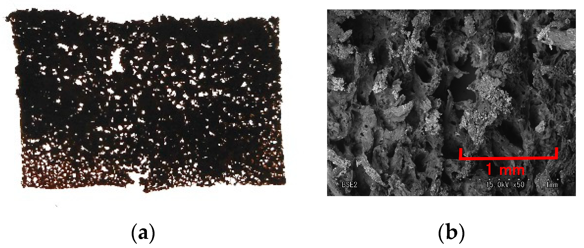
In addition, we allowed the rubber to contain any liquids within the solid rubber via electrolytic polymerization using a metal complex hydrate. By electrolytically polymerizing the rubber mixed with a metal hydrate such as sodium tungstate (VI) dihydrate (Na2WO4·2H2O) and water, we created solidified rubber that was porous, like a sponge (Figure A1 in the Appendix A). Therefore, by pouring a liquid into the porous rubber, evacuating the air, and permeating the liquid with a vacuum pump, the solid rubber could contain a liquid. This is a novel technique for producing a porous capacitor, in contrast to the tried-and-true techniques of using porous carbon material [46], producing a sponge [48], or making mesh structures [49]. Therefore, in the present study, we used the agents and fillers listed in Table 2. For the electrolytic polymerization, a magnetic field of 490 mT was applied to the developed MCF rubber liquid, the electric field was held constant at 6 V, and 2.7 A was supplied between the plates at 10 min periods. Al2O3 has a mean diameter of 3 μm. KI + I2 is the solution compounded with 3.3 g I2 in a solution of 40 g potassium iodide KI and 60 g water.
3.2. Experimental Procedure
Firing rate is an effective measure for the response of cutaneous receptors to external stimuli such as force, temperature, taste, odors, and scents. In the human body, it is evaluated as the electric current created by the action of electrons, electron hole, and ions in traversing the neurons. Therefore, the voltage from the developed MCF rubber was measured using a voltage meter (PC710; Sanwa Electric Instrument Co., Ltd., Tokyo, Japan) when the developed MCF rubber was compressed by the instrument shown in Figure 1.
The firing rate depends on the inductance and capacitance of the cutaneous receptors [50]. By evaluating the firing rate, we could evaluate the morphology of the electric circuit of the developed MCF rubber. The electric properties could be measured via electrochemical impedance spectroscopy (EIS) [51]. Those of the developed MCF rubber were then measured with an LCR meter (IM3536; Hioki Co., Ltd., Ueda, Japan). Because the measurement of the electric properties involving impedance, inductance, etc., is demonstrated as the sensibility of the MCF rubber, and the electric properties were the main target in the present study, we ascertained the accuracy of the electric properties as follows: we used the current four-terminal method with four terminal probes in the measurement by EIS using a LCR meter, which is so significant that the error of the electric properties can be reduced to be measured accurately.
3.3. Results and Discussion
3.3.1. Electrochemical Mechanism
Figure 6 presents the results of the developed MCF rubber with porous EIS. The firing rate is mainly categorized as either slow adaption (SA) or fast adaption (FA) to the applied force, as shown in Figure 7a–d. FA is characterized by a peak of the voltage, while in SA, changes in the voltage are smooth; the other type (OT) is characterized by fluctuating voltage changes. We discuss the experimental results of the firing rates of SA, FA, and OT in the next section. However, to clarify the relationship between the intrinsic structure and electrochemical mechanism, we use the FA, SA, and OT index in the following explanations. The firing rate depends on the inductance L and capacitance C when the developed MCF rubber has electric circuits, as shown in Figure 7e, and explained in a previous study [50]: that is, SA as larger C, and FA as larger L. The numerical subscripts L, C, and R “2, 2,1, 2,2” correspond to the illustration in the previous study [50]. As shown in Figure 6a,b, the quantitative value of the Lp is the reverse of that of Cp, and the developed MCF rubbers are categorized as follows.
FA: C6H5Li3O7·4H2O, PVA
SA: glycerine, glycerine + BaTiO3, glycerine + Al2O3
OT: water, KI + I2
As shown in Figure 6c,d, the quantitative order of the impedance Z is the same as that of the resistance Rp. This tendency denotes that the effect of the resistor dominates the developed MCF rubber. The qualitative tendency of Z is different with FA, SA and OT, as shown in Figure 8, and is indicated by the red line in the figure, which is summarized by the totals of Lp, Cp, and Rp, respectively. The parameters of Lp, Cp, and Rp stem from the intrinsic structure, as shown in Figure 9. The agents in the porous rubber respond to the molecules and particles of the magnetic clusters, such as the electrochemical response shown in Figure 3. As shown in C of Figure 4, Lp and Rp are created by the built-in current induced by the behavior of electrons, holes, and positive ions, and Cp by the built-in voltage.
Figure 6e shows the absolute reactance X, and is categorized by FA, SA, and OT, as shown in Figure 10. This can be summarized as follows. The profile of FA has a peak because it enhances Lp, while that of SA does not have a peak because it only enhances Cp, whose tendencies are the same as that of Z, as shown in Figure 8a,c. The profile of OT includes the factor of FA, and so has a peak.
In general, the relationship between Rp and reactance X is best shown as a Cole–Cole or Niquist plot to clarify the electrochemical and physical mechanism of the intrinsic structure for the solid dielectric capacitor or ionic conductor [19]. As shown in Figure 6f–h, for FA, X is negative at the smaller Rp. It is in the region of higher frequency that the effect of C is larger, as shown in Figure 8a. In contrast, X is positive at the largest Rp. It is in the region of smaller frequency that the effects of L (shown in Figure 8a) and R are larger (because the tendency of the quantitative order of Lp is the same as that of Rp, as shown in Figure 6a,c). These tendencies indicate that the developed MCF rubber demonstrates PC, but not EDLC, because the negative X means the R-C-parallel electric circuits shown in Figure 7e, and the profile of X to Rp, digress from the sharp shape of the semi-circle of an SC. If the profile of X to Rp has a sharp semi-circle shape, the material is EDLC. Furthermore, PC demonstrates any conditions whether a RDPC, IPC, DPC, or UPC dose. On the other hand, for SA, X is negative at overall Rp, so the developed MCF rubber demonstrates PC. X is negative for OT at overall Rp; however, X decreases and then increases with decreasing Rp. This shows that the developed MCF rubber demonstrates PC, but that the behavior of the SC providing SA is different from that of OT. The difference is due to that the fact that C is enhanced in the case of SC providing OT, as shown in Figure 8c, and that the effect of R dominates, but not R in the case of SC providing SA, as shown in Figure 8b. The results of FA, SA, and OT are summarized in Figure 11.
3.3.2. Firing Rate
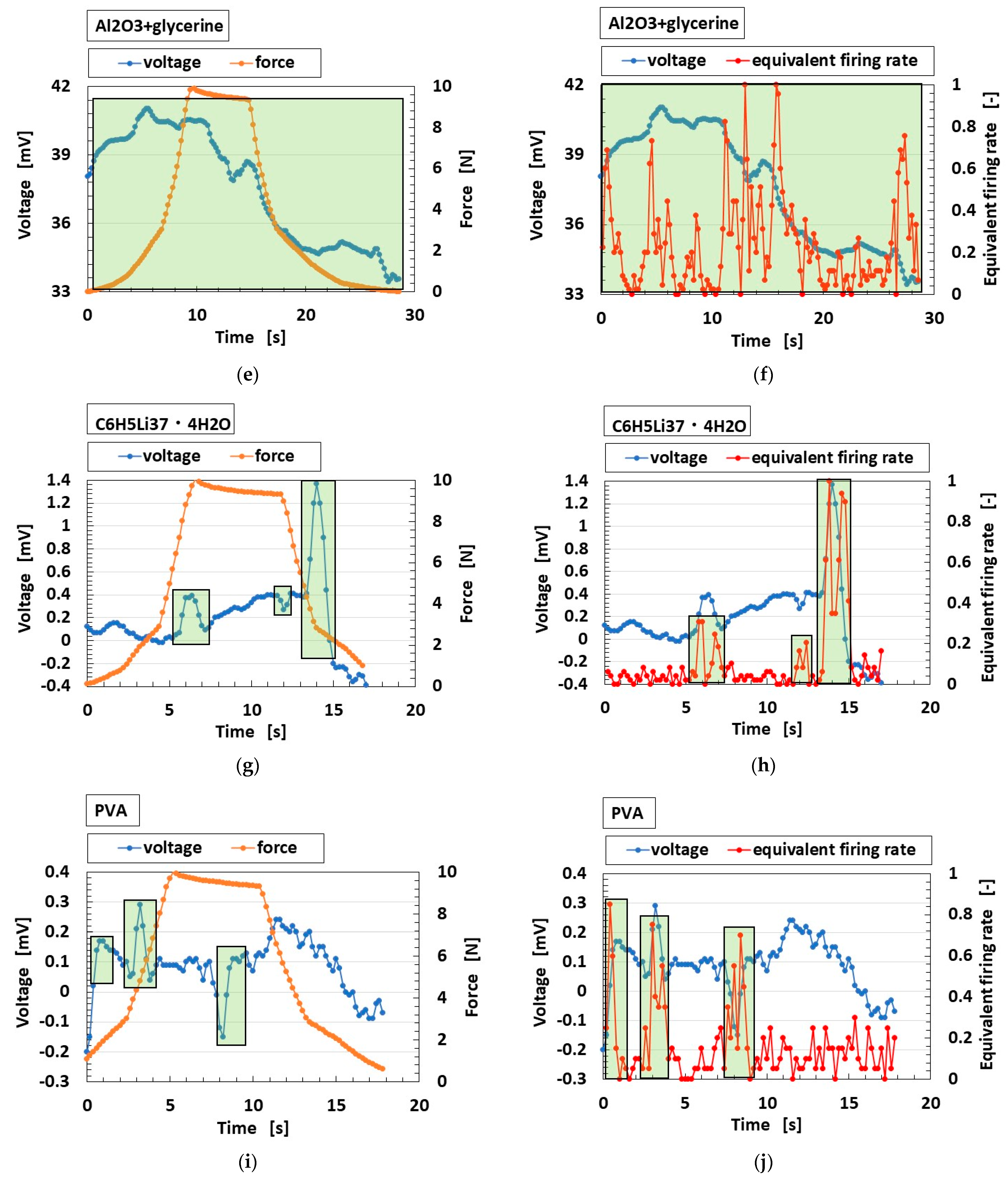
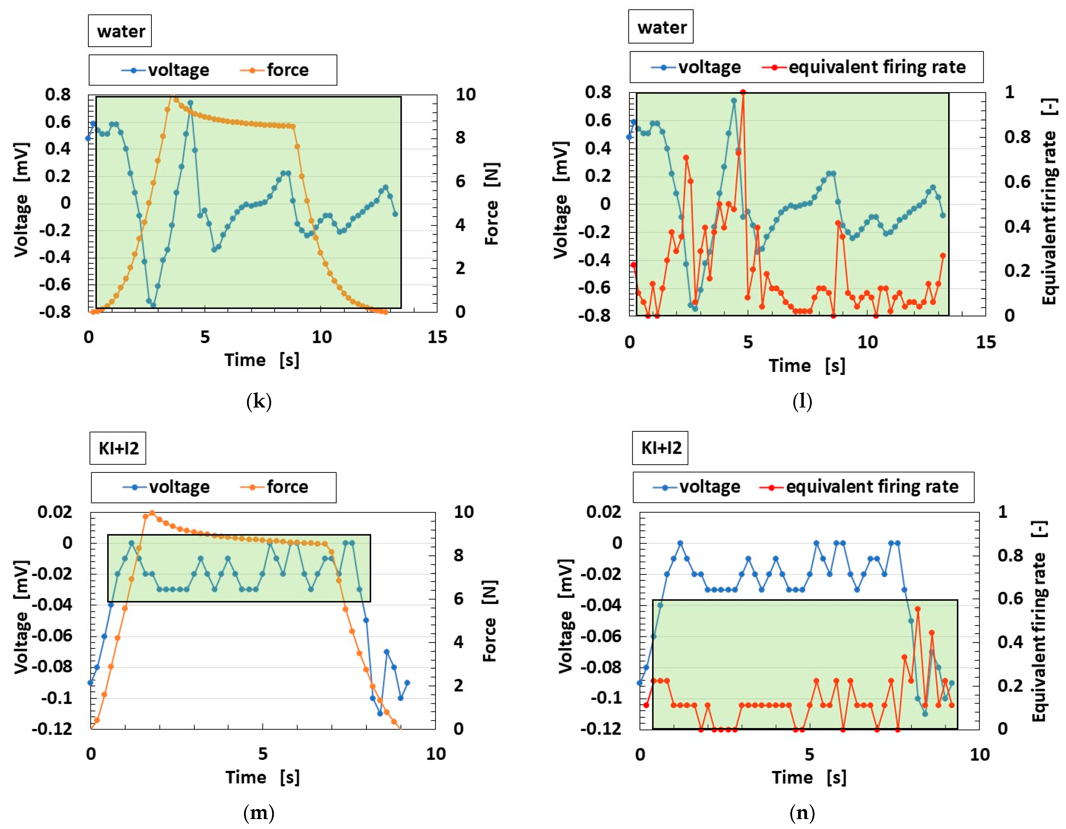
Figure 12 shows the voltage from the developed MCF rubber reacting to the applied force. The firing rate can be estimated as the gradient of the changing voltage, which is equivalent to firing rate [50]. The light-green area is the response of the voltage. The area of changing voltage in Figure 12a–f demonstrates the profile of Figure 7c (corresponding to SA), Figure 12g–j the profile of Figure 7b (corresponding to FA), and Figure 12k–n the profile of Figure 7d (corresponding to OT). Regarding the voltage, FA is characterized by a typical peak, SA by a smooth profile similar to a trapezoid, and OT by many fluctuations.
4. Conclusions
From the CV profiles and electric properties of EIS, the intrinsic structure of the MCF rubber containing fillers and agents can be morphologically evaluated. In addition, the electrochemical mechanism of the molecules and particles behavior can be estimated.
At first, by doping the fillers of solid material, the MCF rubber has a faradaic process of a linear I–V profile, and I increases to V with enhanced pressure. It gains an electrochemical response in which EDLC is dominant: a faradaic reaction is created at the EDL. In contrast, by doping the agents of liquid, it has a non-linear I–V profile, and the area of the I–V profile increases with enhanced pressure. This corresponds to the electrochemical response to be PC, whose behavior changes from EDLC with the redox generated at the EDL. The generation of the redox, etc., results from the electrochemical reaction between the molecules of rubber, particles of the magnetic clusters, and the agents. Therefore, the PC demonstrates any RDPC, IPC, DPC, or UPC. Those consequences demonstrate that the agents are critical to the electrochemical response, and to deducing the intrinsic structure of the MCF rubber.
Next, the firing rate in the case of utilizing the MCF rubber with the bio-inspired sensors with cutaneous receptors can be categorized into three types: FA, SA, and OT. As seen from the voltage response of the sensors, FA is characterized by a typical peak, SA by a smooth profile similar to a trapezoid, and OT by having many fluctuations. The categories are derived from the electric properties by EIS, which is relevant to the intrinsic structure. Lp is dominant at a smaller frequency and Cp at a larger frequency in FA so that Z has a convex-like peak profile of frequency. In addition, X is negative at smaller Rp and positive at largest Rp. The results show that the MCF rubber demonstrates PC, whether a RDPC, IPC, DPC, or UPC dose. Cp demonstrated in the MCF rubber results from the built-in voltage between the static ions facing each other. Lp and Rp result from the mobile built-in current of ions and electrons. In contrast, as for SA, Z decreases at overall frequency; as for OT, Z decreases at larger frequency. Cp is dominant in SA and OT and so X is negative at overall Rp. The results provide that the MCF rubber demonstrated such as a PC. However, the difference between SA and OT is that X decreases and then increases with decreasing Rp as for OT, and demonstrates that the behavior of PC providing SA is different from that of OT.
The electrochemical framework of the SC is commonly used in the field of solid dielectric capacitors or ionic conductors in order to enhance the efficiency of energy storage. However, because the SC has the properties of capacitance, inductance, and resistance, a sensor utilizing the response to extraneous stimuli should also be expected for novel production. In particular, by controlling capacitance and inductance with the types of doped agents used, sharp and slow responses are feasible, and can be easily evaluated by firing rate. The findings obtained in the present study are useful for these novel capacitors and sensors.
Funding
This work was partially supported by JSPS KAKENHI Grant Number JP 21K03960.
Institutional Review Board Statement
Not applicable.
Informed Consent Statement
Not applicable.
Data Availability Statement
Not applicable.
Acknowledgments
This study was made possible largely due to support from a JSPS KAKENHI Grant. The author would like to acknowledge the generosity of these organizations.
Conflicts of Interest
The funding sponsors had no role in the design of the study. The author has no conflict of interest to declare.
Appendix A
Figure A1 contains images of the porous electrolytically polymerized MCF rubber from an optical microscope and scanning electron microscope (SEM) [52]. Its constitution is 0.5 g Na2WO4·2H2O, 3 g water, 0.75 g MF, 0.5 g TiO2, 3 g S-500, 3 g 671A, and 3 g Ni. For the electrolytic polymerization, 30 V and 2.7 A were applied for 5 min with a 1 mm gap between the electrodes.
Figure A1.
Images of the porous electrolytically polymerized MCF rubber: (a) panoramic image of rubber facing cathode by optical microscope; (b) SEM image with 50X magnification [52].
Figure A1.
Images of the porous electrolytically polymerized MCF rubber: (a) panoramic image of rubber facing cathode by optical microscope; (b) SEM image with 50X magnification [52].
References
- Khandelwal, G.; Dahiya, R. Self-powered active sensing based on triboelectric generators. Adv. Mater. 2022, 34, 2200724. [Google Scholar] [CrossRef] [PubMed]
- Zhou, Y.S.; Zhu, G.; Niu, S.; Liu, Y.; Bai, P.; Jing, Q.; Wang, Z.L. Nanometer resolution self-powered static and dynamic motion sensor based on micro-grated triboelectrification. Adv. Mater. 2014, 26, 1719. [Google Scholar] [CrossRef] [PubMed]
- Zhang, B.; Zhang, L.; Deng, W.; Jin, L.; Chun, F.; Pan, H.; Gu, B.; Zhang, H.; Lv, Z.; Yang, W.; et al. Self-powered acceleration sensor based on liquid metal triboelectric nanogenerator for vibration monitoring. ACS Nano 2017, 11, 7440. [Google Scholar] [CrossRef] [PubMed]
- Li, T.; Zhou, J.; Xing, F.; Zhang, M.; Cao, X.; Wang, N.; Wang, L. From dual-mode triboelectric nanogenerator to smart tactile sensor: A multiplexing design. ACS Nano 2017, 11, 3950. [Google Scholar] [CrossRef]
- Su, Y.; Wang, J.; Wang, B.; Yang, T.; Yang, B.; Xie, G.; Zhou, Y.; Zhang, S.; Tai, H.; Cai, Z.; et al. Alveolus-inspired active membrane sensors for self-powered wearable chemical sensing and breath analysis. ACS Nano 2020, 14, 6067. [Google Scholar] [CrossRef] [PubMed]
- Zhang, H.; Yang, Y.; Su, Y.; Chen, J.; Hu, C.; Wu, Z.; Liu, Y.; Wong, C.P.; Bando, Y.; Wang, Z.L. Triboelectric nanogenerator as self-powered active sensors for detecting liquid/gaseous water/ethanol. Nano Energy 2013, 2, 693. [Google Scholar] [CrossRef]
- Khandelwal, G.; Ediriweera, M.K.; Kumari, N.; Raj, N.P.M.J.; Cho, S.K.; Kim, S.-J. Metal-amino acid nanofibers based triboelectric nanogenerator for self-powered thioacetamide sensor. ACS Appl. Mater. Interfaces 2021, 13, 18887. [Google Scholar] [CrossRef]
- Qi, S.; Guo, H.; Chen, J.; Fu, J.; Hu, C.; Yu, M.; Wang, Z.L. Magnetorheological elastomers enabled high-sensitive self-powered tribo-sensor for magnetic field detection. Nanoscale 2018, 10, 4745. [Google Scholar] [CrossRef]
- Su, L.; Zhao, Z.X.; Li, H.Y.; Yuan, J.; Wang, Z.L.; Cao, G.Z.; Zhu, G. High-performance organolead halide perovskite-based self-powered triboelectric photodetector. ACS Nano 2015, 9, 11310. [Google Scholar] [CrossRef]
- Jie, Y.; Wang, N.; Cao, X.; Xu, Y.; Li, T.; Zhang, X.; Wang, Z.L. Self-powered triboelectric nanosensor with poly(tetrafluoroethylene) nanoparticle arrays for dopamine detection. ACS Nano 2015, 9, 8376. [Google Scholar] [CrossRef]
- Jung, Y.K.; Kim, K.N.; Baik, J.M.; Kim, B.-S. Self-powered triboelectric aptasensor for label-free highly specific thrombin detection. Nano Energy 2016, 30, 77. [Google Scholar] [CrossRef]
- Pao, Y.-P.; Yu, C.-C.; Lin, Y.-Z.; Chatterjee, S.; Saha, S.; Tiwari, N.; Huang, Y.-T.; Wu, C.-C.; Choi, D.; Lin, Z.-H. Carbohydrate-protein interactions studied by solid-liquid contact electrification and its use for label-free bacterial detection. Nano Energy 2021, 85, 106008. [Google Scholar] [CrossRef]
- Li, W.D.; Ke, K.; Jia, J.; Pu, J.H.; Zhao, X.; Bao, R.Y.; Liu, Z.Y.; Bai, L.; Zhang, K.; Yang, M.B.; et al. Recent advances in multiresponsive flexible sensors towards e-skin: A delicate design for versatile sensing. Small 2021, 18, 2103734. [Google Scholar] [CrossRef]
- Mehrali, M.; Bagherifard, S.; Akbari, M.; Thakur, A.; Mirani, B.; Mehrali, M.; Hasany, M.; Orive, G.; Das, P.; Emneus, J.; et al. Blending electronics with the human body: A pathway toward a cybernetic future. Adv. Sci. 2018, 5, 1700931. [Google Scholar] [CrossRef] [PubMed]
- Dahiya, A.S.; Thireau, J.; Boudaden, J.; Lal, S.; Gulzar, U.; Zhang, Y.; Gil, T.; Azemard, N.; Ramm, P.; Kiessling, T.; et al. Review-energy autonomous wearable sensors for smart healthcare: A review. J. Electrochem. Soc. 2020, 167, 037516. [Google Scholar] [CrossRef]
- Sang, M.; Kim, K.; Shin, J.; Yu, K.J. Ultra-thin flexible encapsulating materials for soft bio-integrated electronics. Adv. Sci. 2022, 9, 2202980. [Google Scholar] [CrossRef] [PubMed]
- Heng, W.; Solomon, S.; Gao, W. Flexible electronics and devices as human-machine interfaces for medical robotics. Adv. Mater. 2022, 34, 2107902. [Google Scholar] [CrossRef]
- Bubniene, U.S.; Ratautatite, V.; Ramanavicius, A.; Bucinskas, V. Conducting polymers for the design of tactile sensors. Polymers 2022, 14, 2984. [Google Scholar] [CrossRef]
- Kim, T.Y.; Suh, W.; Jeong, U. Approaches to deformable physical sensors: Electronic versus iontronic. Mater. Sci. Eng. R. Rep. 2021, 146, 100640. [Google Scholar] [CrossRef]
- Ding, Q.; Wu, Z.; Tao, K.; Wei, Y.; Wang, W.; Yang, B.R.; Xie, X.; Wu, J. Environment tolerant, adaptable and stretchable organohydrogels: Preparation, optimization, and applications. Mat. Horiz. 2022, 9, 1356–1386. [Google Scholar] [CrossRef]
- Bao, S.; Gao, J.; Xu, T.; Li, N.; Chen, W.; Lu, W. Anti-freezing and antibacterial conductive organohydrogel co-reinforced by 1D silk nanofibers and 2D graphitic carbon nitride nanosheets as flexible sensor. Chem. Eng. J. 2021, 411, 128470. [Google Scholar] [CrossRef]
- Chen, J.; Lee, P.S. Electrochemical supercapacitors: From mechanism understanding to multifunctional applications. Adv. Energy Mater. 2021, 11, 2003311. [Google Scholar] [CrossRef]
- Swain, N.; Tripathy, A.; Thirumurugan, A.; Saravanakumar, B.; Mende, L.S.; Ramadoss, A. A brief review on stretchable, compressible, and deformable supercapacitor for smart devices. Chem. Eng. J. 2022, 446, 136876. [Google Scholar] [CrossRef]
- Shimada, K. Enhancement of MCF rubber utilizing electric and magnetic fields, and clarification of electrolytic polymerization. Sensors 2017, 17, 767. [Google Scholar] [CrossRef] [PubMed]
- Shimada, K.; Ikeda, R.; Kikura, H.; Takahashi, H. Development of novel magnetic responsive intelligent fluid, hybrid fluid (HF), for production of soft and tactile rubber. World J. Mech. 2021, 11, 187–203. [Google Scholar] [CrossRef]
- Hamann, W. Mammalian cutaneous mechanoreceptors. Prog. Biophys. Mol. Biol. 1995, 64, 81–104. [Google Scholar] [CrossRef] [PubMed]
- Tomar, R. Review: Methods of firing rate estimation. BioSystems 2019, 183, 103980. [Google Scholar] [CrossRef]
- Kobayakawa, T.; Gotow, N. Interaction between olfaction and gustation by using synchrony perception task. i-Perception 2011, 2, 964. [Google Scholar] [CrossRef]
- Gotow, N.; Kobayakawa, T. Simultaneity judgment using olfactory-visual, visual-gustatory, and olfactory-gustatory combinations. PLoS ONE 2017, 12, e0174958. [Google Scholar] [CrossRef]
- Shimada, K. Morphological configuration of sensory biomedical receptors based on structures integrated by electric circuits and utilizing magnetic-responsive hybrid fluid (HF). Sensors 2022, 22, 9952. [Google Scholar] [CrossRef]
- Jang, S.H.; Park, Y.L.; Yin, H. Influence of coalescence on the anisotropic mechanical and electrical properties of nickel powder/polydimethylsiloxane composites. Materials 2016, 9, 239. [Google Scholar] [CrossRef]
- Patil, A.R.; Dongale, T.D.; Kamat, R.K.; Rajpure, K.Y. Binary metal oxide-based resistive switching memory devices: A status review. Mater. Today Commu. 2023, 34, 105356. [Google Scholar] [CrossRef]
- Wu, X.; Lu, C.; Han, Y.; Zhou, Z.; Yuan, G.; Zhang, X. Cellulose nanowhisker modulated 3D hierarchical conductive structure of carbon black/natural rubber nanocomposites for liquid and strain sensing application. Compos. Sci. Technol. 2016, 124, 44–51. [Google Scholar] [CrossRef]
- Sahatiya, P.; Badhulika, S. Eraser-based eco-friendly fabrication of a skin-like large-area matrix of flexible carbon nanotube strain and pressure sensors. Nanotechnology 2017, 28, 095501. [Google Scholar] [CrossRef]
- Bao, R.; Wang, C.; Dong, L.; Yu, R.; Zhao, K.; Wang, Z.L.; Pan, C. Flexible and controllable piezo-phototronic pressure mapping sensor matrix by ZnO NW/p-polymer LED array. Adv. Func. Mater. 2015, 25, 2884–2891. [Google Scholar] [CrossRef]
- Wang, S.; Hu, X.; Dai, Y. preparation and electrochemical performance of polymer-derived SiBCN-graphene composite as anode material for lithium ion batteries. Ceram. Int. 2017, 43, 1210–1216. [Google Scholar] [CrossRef]
- Ding, X.; Shao, H.; Wang, H.; Yang, W.; Fang, J.; Zhang, D.; Lin, T. Schottky DC generators with considerable enhanced power output and energy conversion efficiency based on polypyrrole-TiO2 nanocomposite. Nano Energy 2021, 89, 106367. [Google Scholar] [CrossRef]
- Ponnamma, D.; Cabibihan, J.J.; Rajan, M.; Pethaiah, S.S.; Deshmukh, K.; Gogoi, J.P.; Pasha, S.K.K.; Ahamed, M.B.; Krishnegowda, J.; Chandrashekar, B.N.; et al. Synthesis, optimization and applications of ZnO/polymer nanocomposites. Mater. Sci. Eng. C 2019, 98, 1210–1240. [Google Scholar] [CrossRef]
- Li, S.; Chen, H.; Liu, X.; Li, P.; Wu, W. Nanocellulose as a promising substrate for advanced sensors and their applications. Int. J. Biolog. Macromol. 2022, 218, 473–487. [Google Scholar] [CrossRef]
- Moftah, A.; Shetiti, A.A. Review of super capacitor technology. Indones. J. Comput. Sci. Electr. Eng. 2015, 3, 226–231. [Google Scholar]
- Jiang, Y.; Liu, J. Definitions of pseudocapacitive materials: A brief review. Energy Environ. Mater. 2019, 2, 30–37. [Google Scholar] [CrossRef]
- Guan, J.; Li, Y.; Li, J. Stretchable ionic-liquid-based gel polymer electroryles for lithium-ion batteries. Ind. Eng. Chem. Res. 2017, 56, 12456–12463. [Google Scholar] [CrossRef]
- Forouzandeh, P.; Kumaravel, V.; Pillai, S.C. Electrode materials for supercapacitors: A review of recent advances. Catalysts 2020, 10, 969. [Google Scholar] [CrossRef]
- Wang, J.; Dong, S.; Ding, B.; Wang, Y.; Hao, X.; Dou, H.; Xia, Y.; Zhang, X. Pseudocapacitive materials for electrochemical capacitors: From rational synthesis to capacitance optimization. Natl. Sci. Rev. 2017, 4, 71–90. [Google Scholar] [CrossRef]
- Liu, Y.; Jiang, S.P.; Shao, Z. Intercalation pseudocapacitance in electrochemical energy storage: Recent advances in fundamental understanding and materials development. Mater. Today Adv. 2020, 7, 100072. [Google Scholar] [CrossRef]
- Xie, L.; Su, F.; Xie, L.; Guo, X.; Wang, Z.; Kong, Q.; Sun, G.; Ahmad, A.; Li, X.; Yi, Z.; et al. Effect of pore structure and doping species on charge storage mechanisms in porous carbon-based supercapacitors. Mater. Chem. Front. 2020, 4, 2610–2634. [Google Scholar] [CrossRef]
- Dickinson, E.J.F.; Wain, A.J. The butler-Volmer equation in electrochemical theory: Origins, value, and practical application. J. Electroanalyt. Chem. 2020, 872, 114145. [Google Scholar] [CrossRef]
- Yu, Y.; Meng, Q.; Liu, T. Multifunctional and durable graphene-based composite sponge doped with antimonene nanosheets. J. Mater. Res. Technol. 2022, 17, 2466–2479. [Google Scholar] [CrossRef]
- Gong, M.; Zhang, L.; Wan, P. Polymer nanocomposite meshes for flexible electronic devices. Prog. Polym. Sci. 2020, 107, 101279. [Google Scholar] [CrossRef]
- Shimada, K. Correlations among firing rates of tactile, thermal, gustatory, olfactory and auditory sensations mimicked by artificial hybrid fluid (HF) rubber mechanoreceptors. Sensors 2023, 23, 4593. [Google Scholar] [CrossRef]
- Lu, Y.; Ru, S.; Li, H.; Wang, G.; Xu, S. Laser-structured microarray electrodes for durable stretchable lithium-ion battery. J. Colloids Inter. Sci. 2023, 631, 1–7. [Google Scholar] [CrossRef] [PubMed]
- Shimada, K.; Ikeda, R.; Kikura, H.; Takahashi, H. Enhancement of diversity on production and application utilizing electrolytically polymerized rubber sensors with MCF: 1st report on consummate fabrication combining varied kinds of constituents with porous permeant stocking-like rubber. Sensors 2020, 20, 4658. [Google Scholar] [CrossRef] [PubMed]
Figure 1.
Schematic diagram of experimental apparatus for investigating the intrinsic structure of the MCF rubber and firing rate.
Figure 1.
Schematic diagram of experimental apparatus for investigating the intrinsic structure of the MCF rubber and firing rate.

Figure 2.
CV profiles of MCF rubber at varying pressures: (a) Type A (normal); (b) Type B (+ZnO); (c) Type C (+TiO2); (d) Type D (+KI); (e) Type E (+KOH); (f) Type F (+KI, KOH); (g) Type G (+ZnO, TiO2, KI); (h) Type H (+ZnO, TiO2, KI, KOH); the arrows mean the enhancing by increasing force.
Figure 2.
CV profiles of MCF rubber at varying pressures: (a) Type A (normal); (b) Type B (+ZnO); (c) Type C (+TiO2); (d) Type D (+KI); (e) Type E (+KOH); (f) Type F (+KI, KOH); (g) Type G (+ZnO, TiO2, KI); (h) Type H (+ZnO, TiO2, KI, KOH); the arrows mean the enhancing by increasing force.

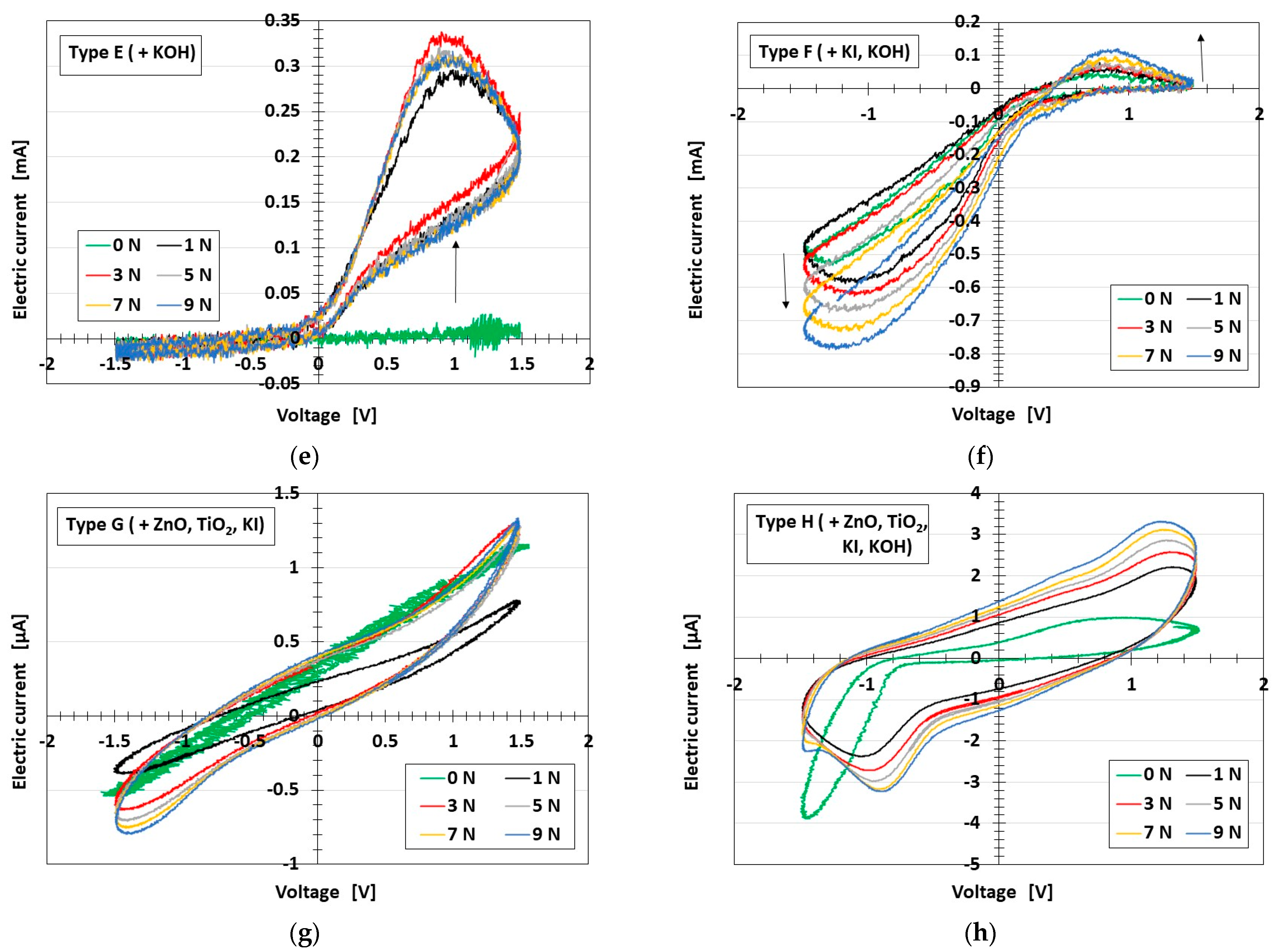
Figure 3.
Relationship between the intrinsic structure of MCF rubber and the reaction with the role of SC.
Figure 3.
Relationship between the intrinsic structure of MCF rubber and the reaction with the role of SC.
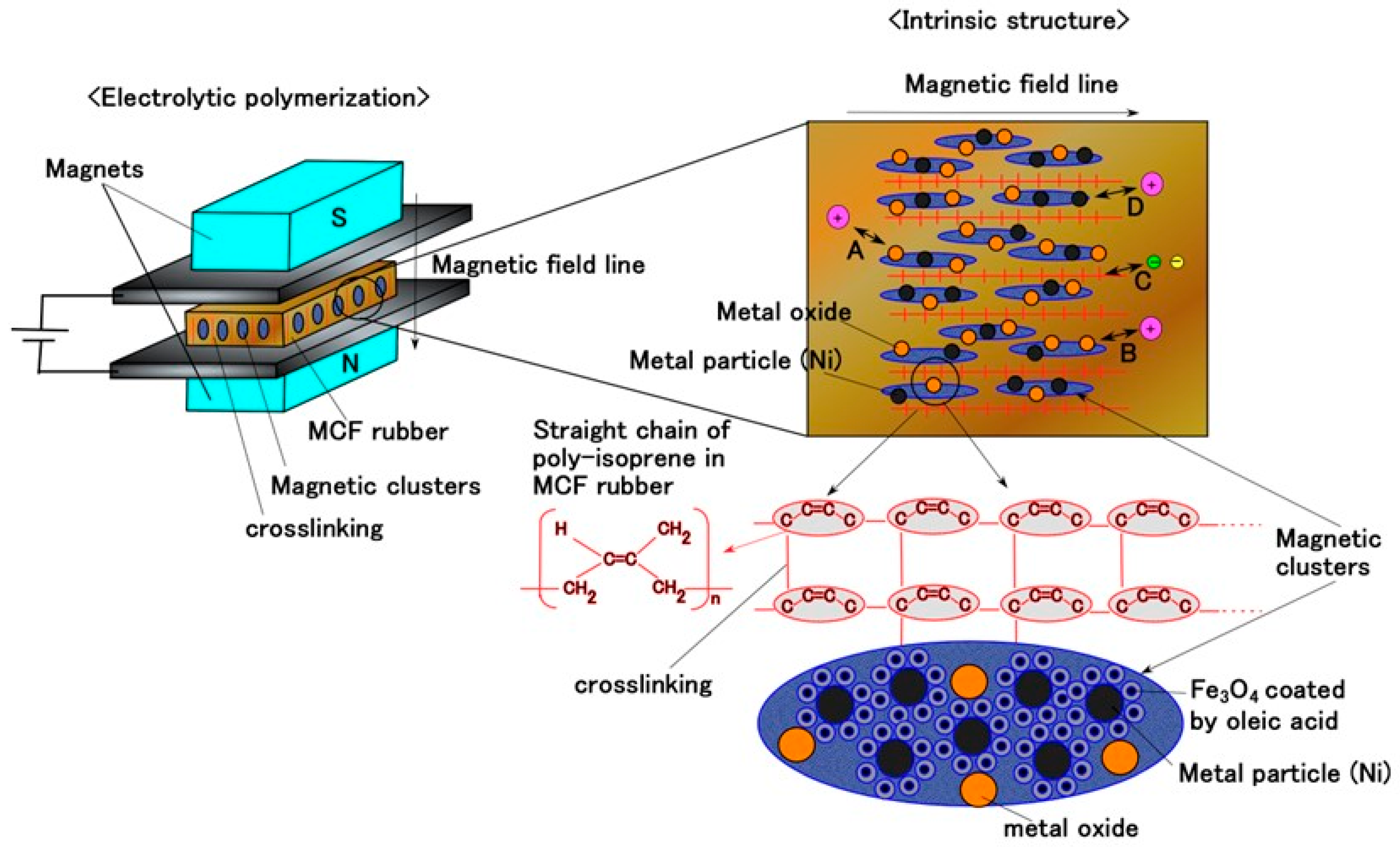
Figure 4.
Physical model of the intrinsic structure of MCF rubber.

Figure 5.
Comparison of CV profile of PC, EDLC, resistive capacitor, and ideal capacitor.
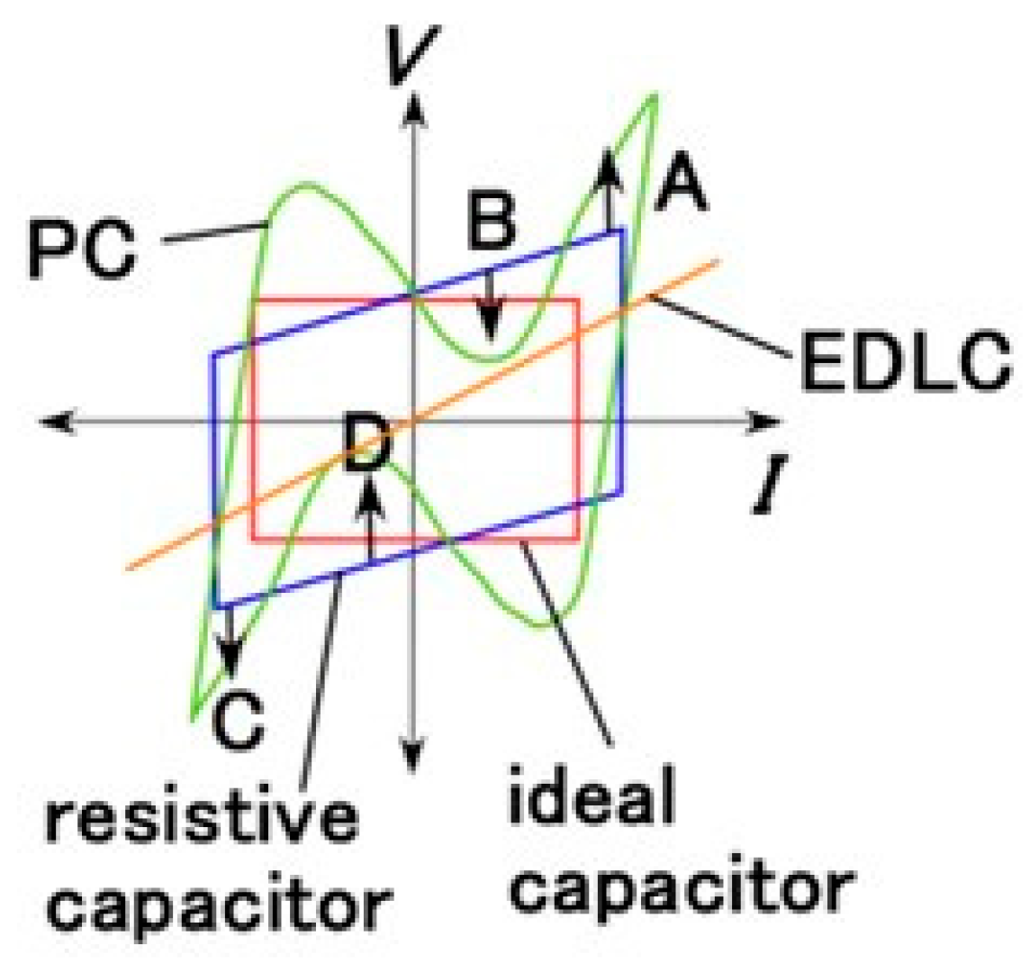
Figure 6.
EIS results of the developed MCF rubber: (a) inductance; (b) capacitance; (c) resistance; (d) impedance; (e) absolute reactance; (f) reactance to resistance; (g) magnification of the A in (f); (h) magnification of the B in (g).
Figure 6.
EIS results of the developed MCF rubber: (a) inductance; (b) capacitance; (c) resistance; (d) impedance; (e) absolute reactance; (f) reactance to resistance; (g) magnification of the A in (f); (h) magnification of the B in (g).


Figure 7.
Illustration of firing rate tendency and electric circuits of the developed MCF rubber: (a) applied force; (b) FA; (c) SA; (d) OT; (e) electric circuits with resistor R2, inductor L2, and capacitor C2,1 [39], where the numerical subscripts L, C, and R as “2, 2,1, 2,2” correspond to the illustration in our previous study [39].

Figure 8.
Illustration of impedance tendency of the developed MCF rubber corresponding to electric circuits: (a) FA; (b) SA; (c) OT.
Figure 8.
Illustration of impedance tendency of the developed MCF rubber corresponding to electric circuits: (a) FA; (b) SA; (c) OT.


Figure 9.
Physical model of intrinsic structure of the developed porous MCF rubber.
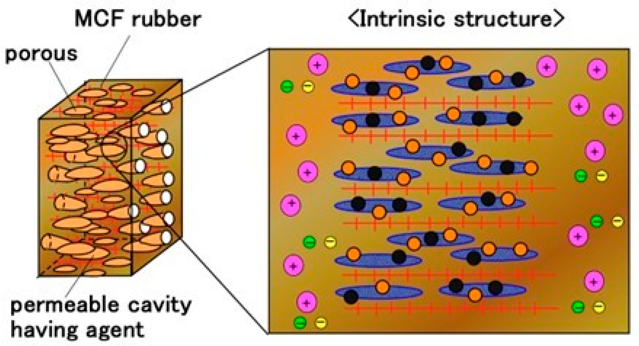
Figure 10.
Illustration of absolute reactance tendency of the developed MCF rubber on FA, SA and OT.
Figure 10.
Illustration of absolute reactance tendency of the developed MCF rubber on FA, SA and OT.
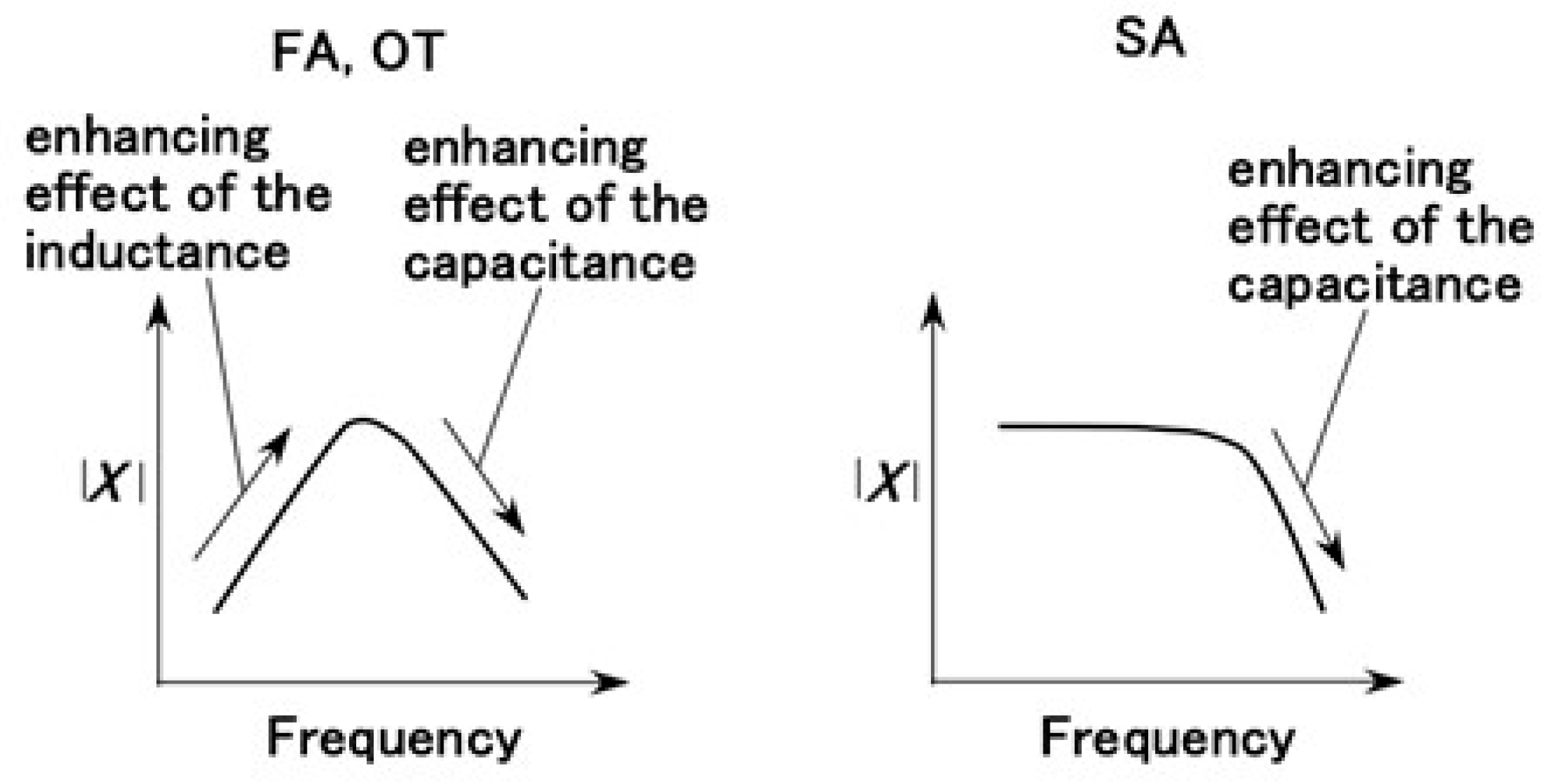
Figure 11.
Illustration of reactance tendency of the developed MCF rubber on FA, SA, and OT.
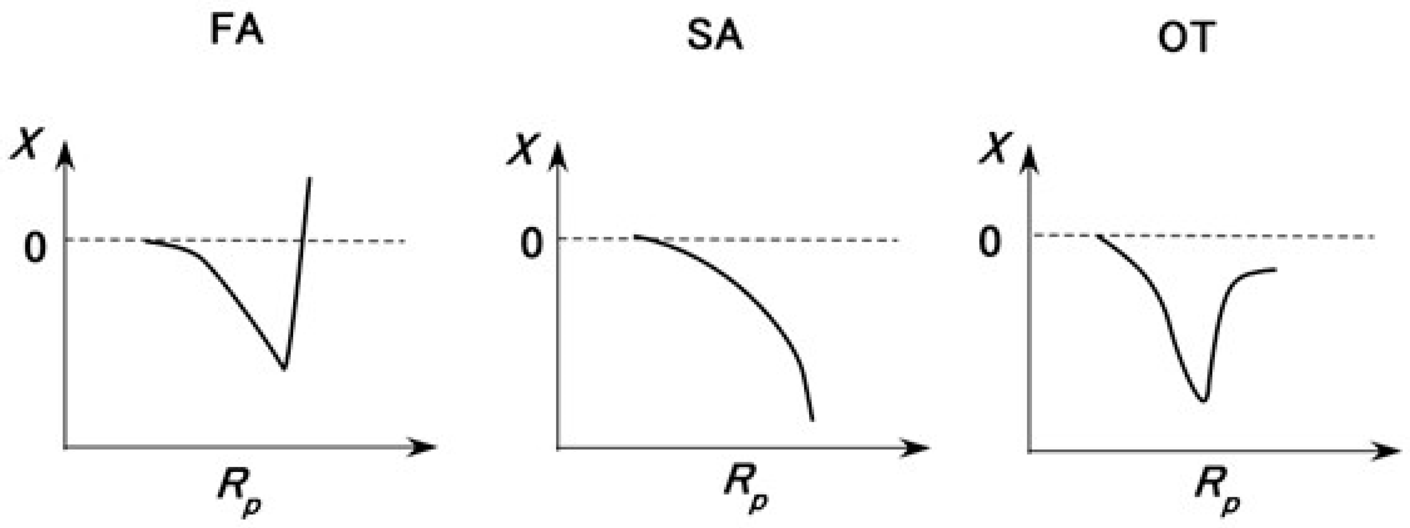
Figure 12.
Changes in voltage and the equivalent firing rate of the developed MCF rubber: (a,b) glycerine; (c,d) glycerine + BaTiO3; (e,f) glycerine + Al2O3; (g,h) C6H5Li3O7·4H2O; (i,j) PVA; (k,l) water; (m,n) KI + I2.; (a,c,e,g,i,k,m) voltage; (b,d,f,h,j,l,n) equivalent firing rate.
Figure 12.
Changes in voltage and the equivalent firing rate of the developed MCF rubber: (a,b) glycerine; (c,d) glycerine + BaTiO3; (e,f) glycerine + Al2O3; (g,h) C6H5Li3O7·4H2O; (i,j) PVA; (k,l) water; (m,n) KI + I2.; (a,c,e,g,i,k,m) voltage; (b,d,f,h,j,l,n) equivalent firing rate.


Table 1.
Ingredients of the MCF rubber liquid used in this study.
| Type A (Normal) | Type B (+ZnO) | Type C (+TiO2) | Type D (+KI) |
|---|---|---|---|
| Ni: 1.5 g | Ni: 1.5 g | Ni: 1.5 g | Ni: 1.5 g |
| MF: 0.75 g | MF: 0.75 g | MF: 0.75 g | MF: 0.75 g |
| NR latex: 4.5 g | NR latex: 4.5 g | NR latex: 4.5 g | NR latex: 4.5 g |
| - | ZnO: 0.25 g | TiO2: 0.25 g | KI solution: 0.5 g |
| Type E (+KOH) | Type F (+KI, KOH) | Type G (+ZnO, TiO2, KI) | Type H (+ZnO, TiO2, KI, KOH) |
| Ni: 1.5 g | Ni: 1.5 g | Ni: 1.5 g | Ni: 1.5 g |
| MF: 0.75 g | MF: 0.75 g | MF: 1.125 g | MF: 0.75 g |
| NR latex: 4.5 g | NR latex: 4.5 g | NR latex: 4.5 g | NR latex: 4.5 g |
| KOH solution: 1.7 g | KI solution: 0.5 g | ZnO: 0.5 g | ZnO: 0.25 g |
| - | KOH solution: 0.75 g | TiO2: 0.5 g | TiO2: 0.25 g |
| - | - | KI solution: 0.5 g | KI solution: 1.1 g |
| - | - | - | KOH solution: 0.75 g |
Table 2.
Ingredients of the developed MCF rubber used in this study.
| Ni: 1.5 g |
| MF: 0.75 g Na2WO4·2H2O: 0.5 g |
| S-500: 3 g |
| CR latex: 3 g KF96: 3 g PVA: 3 g Compounding fillers or permeating agents (glycerine *1, glycerine + BaTiO3 *2, glycerine *1 + Al2O3 *2, C6H5Li3O7·4H2O *1, water *1, KI + I2 *1, PVA *1) |
*1 permeating into the electrolytically polymerized MCF rubber over 2 h; *2 1 g compounded into the MCF rubber latex during the electrolytic polymerization.
Disclaimer/Publisher’s Note: The statements, opinions and data contained in all publications are solely those of the individual author(s) and contributor(s) and not of MDPI and/or the editor(s). MDPI and/or the editor(s) disclaim responsibility for any injury to people or property resulting from any ideas, methods, instructions or products referred to in the content. |
© 2023 by the author. Licensee MDPI, Basel, Switzerland. This article is an open access article distributed under the terms and conditions of the Creative Commons Attribution (CC BY) license (https://creativecommons.org/licenses/by/4.0/).
Share and Cite
MDPI and ACS Style
Shimada, K. Elucidation of Response and Electrochemical Mechanisms of Bio-Inspired Rubber Sensors with Supercapacitor Paradigm. Electronics 2023, 12, 2304. https://doi.org/10.3390/electronics12102304
AMA Style
Shimada K. Elucidation of Response and Electrochemical Mechanisms of Bio-Inspired Rubber Sensors with Supercapacitor Paradigm. Electronics. 2023; 12(10):2304. https://doi.org/10.3390/electronics12102304
Chicago/Turabian StyleShimada, Kunio. 2023. "Elucidation of Response and Electrochemical Mechanisms of Bio-Inspired Rubber Sensors with Supercapacitor Paradigm" Electronics 12, no. 10: 2304. https://doi.org/10.3390/electronics12102304
Note that from the first issue of 2016, this journal uses article numbers instead of page numbers. See further details here.