
Research on Temperature Distribution of Large Permanent Magnet Synchronous Direct Drive Wind Turbine
Department of Mechanical and Electrical Engineering, Beijing Information Science and Technology University, Beijing 100192, China
*
Author to whom correspondence should be addressed.
Electronics 2023, 12(10), 2251; https://doi.org/10.3390/electronics12102251
Submission received: 30 March 2023
/
Revised: 6 May 2023
/
Accepted: 12 May 2023
/
Published: 15 May 2023
(This article belongs to the Special Issue Application of Power Electronics Technology in Energy System)
Abstract
:A wind turbine is a conversion mechanism that converts wind energy into electrical energy, but the conversion efficiency cannot reach 100%, so there is partial loss. These losses are converted into thermal energy, which in turn causes the wind turbine to heat up and affect generator performance. Therefore, the cooling and temperature field analysis of wind turbines is very important. In this paper, an electromagnetic analysis model is established by using the parameters of a 4 MW wind turbine; the losses of each part of the generator under rated load and three-phase short-circuit conditions are calculated, respectively; and the heat source is imported into the workbench fluent software to determine the cooling mode, so as to obtain the magnetic-thermal-flow field coupling model of permanent magnet synchronous direct drive wind turbine. The temperature distribution and temperature rise of the generator are obtained. Under the rated load condition, the overall maximum temperature rise of the wind turbine is 41.4 °C, about 180 mm near the fluid outlet side, which is as high as the winding temperature rises, because the winding is the main heating body. The maximum temperature rise of the rotor model and the permanent magnet model is about 36 °C. Under the three-phase short circuit condition, the temperature distribution of each component is similar to that under the rated load condition, and the temperature near the fluid inlet is low; the lowest is only 29.8 °C. The higher the temperature at the fluid’s outlet, but not close to it, the higher the temperature is when it is about 180 mm away from the fluid’s outlet side. The temperature difference in the same axial length is relatively large, with a maximum temperature difference of about 120 °C. The temperature distribution and temperature rise of the generator are independent of the operating conditions, which mainly affect the value. Additionally, through experimental verification, the minimum error under the rated load condition is 1.05%, the maximum error is 3.3%, and the average error is 2.30%. The minimum error under the three-phase short-circuit condition is 1.5%, the maximum error is 3.62%, and the average error is 2.26%. The difference with the engineering error range requirements is small, indicating the reasonable and effective effectiveness of this method. This study aims to provide a strong reference for analyzing the cooling and magnetic thermal flow field and a coupling analysis of direct drive wind turbines.
1. Introduction
In recent years, under the “dual carbon” goal, the wind power industry has achieved unprecedented development. The basic structure of a permanent magnet synchronous direct drive wind turbine is composed of a rotor, stator core, permanent magnet, stator slot, and stator tooth [1], which is a conversion mechanism that converts wind energy into electrical energy. However, since the conversion efficiency cannot be 100%, there are losses, which are converted into thermal energy, which in turn causes the wind turbine to heat up. If the heat generation is serious, the permanent magnet will be irreversibly demagnetized, which will greatly reduce the power of the generator, shorten its life and even burn it. Therefore, the selection of cooling mode and the study of temperature field distribution of wind turbines are of great significance.
The literature [2] analyzes a 5 MW doubly-fed wind turbine model used to study the thermal conductivity, rheological characteristics, and coupling law of fluids in radial ventilation structure, which provides a good reference for the thermal analysis of doubly-fed wind turbines. However, it has little reference value for the study of direct-drive wind turbines. The literature [3] studies the temperature rise distribution law of a 100 KW excitation wind turbine, analyzes the influence of the zero point of excitation current on the temperature distribution, and verifies the relevance by experimental prototype, but only considers the temperature distribution law, and not the generator cooling. The literature [4] proposes a fully enclosed self-circulating air-cooling system with the rotor spoke plate bracket as the centrifugal fan driving the cooling air to achieve a 1.65 MW direct-drive wind turbine model, which improves the reference for wind turbine cooling research. The literature [5] studies the heat transfer characteristics and temperature distribution of 2 MW wind turbines using natural air cooling, which generally has poor effects and cannot meet the generator cooling requirements. The literature [6] studies the temperature distribution law of a water-cooled motor under various working conditions, but the water-cooled structure is complex, which increases the installation and maintenance costs. The literature [7] analyzes the thermal field distribution law of rotor excitation axial flux switch motor, but does not consider cooling. The literature [8] provides a thermal field analysis of a permanent magnet synchronous motor inside a high-speed train, but the temperature rise of the high-speed motor and low-speed high-power generator is different, the corresponding cooling is different, and only one analysis method is provided. Reference [9] conducted thermal analysis on high-speed permanent magnet motor magnetic bearings and conducted experimental verification, providing some reference for thermal analysis of large wind turbines. Reference [10] conducted thermal analysis on high-speed asynchronous spindle motors and designed a certain cooling structure for them, which differs from the thermal distribution of large low-speed wind turbines, but also provides some reference for them. Literature [11] has studied the temperature distribution of the motor of new energy vehicles with heat pipe air cooling system, which can be used for reference with the large low-speed wind turbine with direct air cooling.
The organizational structure of this paper will be as follows: First, introduce the research status of generator thermal analysis, then analyze the generator magnetic field and calculate the generator loss, and finally, analyze the heat transfer principle and generator cooling. Secondly, establish the magnetic heat flow field coupling model, analyze the temperature distribution and temperature rise, and finally, verify the effectiveness and correctness of this method through experiments. In this paper, the loss of 4 MW direct drive wind turbine is calculated by Maxwell2D, and a coupled model of the magnetic-thermal-flow field of the wind turbine is established through workbench fluent; that is, Maxwell2D is used to calculate the electromagnetic loss of the wind turbine, the electromagnetic loss calculation result is coupled to the fluent temperature field and used as a heat source, and the forced air-cooled fluid field is considered to dissipate heat from the wind turbine. Furthermore, the magnetic-thermal-flow multiphysics mapping relationship was established to analyze the temperature distribution law and temperature rise of the motor, and the experimental results showed the reasonable effectiveness of the proposed method.
2. Permanent Magnet Synchronous Direct Drive Wind Turbine Magnetic Field Analysis and Loss Calculation
2.1. Principles of Electromagnetic Analysis
In the magnetic field analysis of permanent magnet synchronous generators, the effect of displacement current is usually ignored, and the electromagnetic field is analyzed as a steady-state field. In the vector magnetic potential in the parallel plane field, the component of the direction of the parallel plane is zero, not considered, and the component of the vertical plane is non-zero. It is necessary to consider that the magnetic potential vector of the permanent magnet synchronous generator meets a certain edge value condition, and its calculation formula is as follows
In the formula: A is the electrical load; v is the magnetoresistivity; J is the current density vector in the vertical plane direction, and the values in the passive region, the applied current region, and the permanent magnet material region are different; Je is the armature current density; and Jm is the equivalent current density of permanent magnets. Equations (3) and (4) are the first and second boundary conditions, respectively. Finite element analysis is dividing a module into a finite number, finding the energy PAN functional corresponding to the magnetic potential partial differential equation, mathematically solving each partition module, discretizing it, and finally obtaining a set of nonlinear and far-distance algebraic differential equations. For example, equations such as (5), and magnetic density and magnetic bits algebraic relations such as (6):
By solving the equation system with Equation (5), the magnetic bit of each node is obtained, and in the algebraic Equation (6), by combining magnetic potential and magnetic density, the magnetic field strength and magnetic density of each node can be obtained simultaneously, and the loss of permanent magnet generator under different working conditions can be analyzed according to the calculated value.
2.2. Maxwell 2D Modeling Analysis
Maxwell is a powerful, accurate, easy-to-use 2D/3D finite element analysis software for electromagnetic fields. The basic process of magnetic field analysis of a permanent magnet synchronous direct drive wind turbine is first to establish a model, define material properties, define working condition boundaries, add external circuit excitation sources, and post-process to obtain the losses of each part of the generator. The basic parameters of the permanent magnet synchronous direct drive wind turbine model are shown in Table 1.
The meshing model of the permanent magnet synchronous direct drive wind turbine is shown in Figure 1, and the tooth division needs to be more detailed to make the calculation more accurate.
2.3. Analysis of Electromagnetic Field Post-Treatment of Generator-Rated Load Conditions
Before post-processing, it is necessary to build an external circuit under rated load conditions of the wind turbine, and the circuit diagram is shown in Figure 2.
In the figure, LPhaseA, LPhaseB, and LPhaseC represent the inductance of the A, B, and C phase windings, respectively, and the naming requirements for them are that, in addition to the first letter L, the latter part must be consistent with the name of the winding excitation in the model, or the corresponding winding in the model will not be automatically matched when the external circuit is introduced. LeA and LeC are the end leakage inductance of the A, B, and C phase windings, respectively. RF is the equivalent resistance of the load in series with each phase. RA, RB, and RC are the internal resistance sizes of the A, B, and C phase windings, respectively.
The Energy loss of wind turbines mainly has four aspects. The first aspect is that the stator winding has a certain resistance value, and there will be copper loss during operation. Copper loss is also the most important loss of the generator. Second, the change of the generator magnetic field will cause eddy current loss and hysteresis loss of the generator core. Third, mechanical losses caused by mechanical friction, such as rotating friction of generator rotor bearings. The fourth aspect is other spurious losses, such as additional losses at load and no load. Since the friction loss and other additional losses of the shaft are much smaller than the copper loss of the winding, they are ignored. The winding copper loss, eddy current loss, and stator and rotor core loss are shown in Figure 3.
It can be seen from the figure that the average winding loss of a wind turbine is 44.4127 KW, the eddy current loss is 0.7256 KW, and the core loss of the stator and rotor is 5.3707 KW.
2.4. Electromagnetic Field Post-Processing of Generator Three-Phase Short-Circuit Working Conditions
For the three-phase short circuit condition of the generator, it is mainly considered that after the sudden change of its current, the current value will become very large, and when it reaches a certain value, irreversible demagnetization will occur. The external circuit of the three-phase short-circuit condition of the wind turbine is shown in Figure 4.
A piezoelectric switch is added between the branches of the main circuit of the load condition, and the use of a pulse voltage source, single-needle grounded voltmeter, and resistance form a secondary circuit, the main function of which is to control the piezoelectric switch and close, in order to achieve the purpose of three-phase short circuit. The winding copper loss, eddy current loss, and stator and rotor core loss in the three-phase short-circuit condition are shown in Figure 5.
It can be seen from the figure that the average winding loss of a wind turbine under a three-phase short-circuit condition is 0.9 megW, the eddy current loss is 0.0002 megW, and the core loss of the stator and rotor is 0.0018 megW.
3. Analysis of Cooling and Heat Transfer Principle of Permanent Magnet Synchronous Direct Drive Wind Turbine
3.1. Select the Cooling Method of Permanent Magnet Synchronous Direct Drive Wind Turbine
The conversion efficiency of wind turbines cannot reach 100%, and part of the losses will be converted into heat energy, which will cause the wind turbine to heat up. Therefore, to ensure the safe and reliable operation of wind turbines, it is necessary to effectively cool the generators so that the temperature is controlled within the allowable range. For the cooling of generators, the current cooling methods mainly include natural air cooling, forced air cooling, water cooling, hydrogen cooling, and double water internal cooling.
- (1)
- The natural air-cooling effect is not good, but the cooling is easy to achieve, the cost is low, the reliability is high, and the maintenance cost is also low. Wind turbines using natural air cooling are generally micro and small with slightly higher speeds, few poles, and a single capacity of less than 1 MW;
- (2)
- The forced air-cooled cooling effect is much better than the natural air-cooling effect, but an independent cooling fan is required, the cost is increased, the structural complexity is increased, the reliability is reduced, and the maintenance cost is relatively increased. Forced air-cooled wind turbines are generally medium and large with high speeds, many poles, and a single capacity between 1 MW and 5 MW;
- (3)
- Water cooling is to design a cooling water jacket on the outer surface of the generator, and use an independent water pump to drive the cooling water to flow continuously in the cooling water jacket; the cooling water needs to be treated by the water treatment system. The cooling effect is much better than the free and forced air cooling effects. However, the cooling water jacket and cold-water treatment system need to consider the turbidity of water, water blockage and leakage, and water is easy to freeze in winter. In addition, the structure is more complex, the reliability is low, and the manufacturing cost, installation cost, and maintenance costs are greatly increased. Water-cooled wind turbines are generally large wind turbines with high speed, many poles, and a single capacity between 5 MW and 10 MW;
- (4)
- Other cooling methods mainly include hydrogen and double water internal cooling, which are rarely used. Mainly used in extra-large wind turbines, such as excitation generators, the capacity has reached 1300 MW, and the permanent magnet generator currently reaches 12 MW. However, the cost is extremely high, the structure is complex, and it is generally not considered.
In summary, the 4 MW, 96-pole, 20 rpm permanent magnet wind turbine designed in this paper adopts an axial forced air-cooled cooling method. As a result, thermal cooling of the stator and rotor, permanent magnet end face, external stator and the outer surface of the stator is mainly carried out through air gap channels and ventilation channels on the rotor surface.
3.2. Analysis of Heat Transfer Principle Permanent Magnet Synchronous Direct Drive Wind Turbine
According to the second law of thermodynamics, heat can only be transferred from a high-temperature object to a low-temperature object. Therefore, if the loss generated by each part of the generator is different, and the heat generated is different, then there must be a temperature difference, which will inevitably lead to heat transfer. There are three main ways of heat transfer: heat conduction, heat radiation, and heat convection.
- (1)
- Heat conduction. The essence of heat conduction’s heat transfer principle is that different objects at different temperatures contact each other or parts of the same object at different temperatures, and the party with the higher temperature transfers kinetic energy to molecules and electrons with low kinetic energy in the lower temperature via molecules and electrons with high internal kinetic energy. In the actual heat transfer, the heat field is transferred in three-dimensional space, and according to the relationship between the temperature field and the heat source established by Myerty, the heat conservation formula is:
It is the heat generated by the heat source temperature field, the heat conducted outward by the volume unit of the heat source temperature field, and the remaining heat of the heat source temperature field. Let the heat source temperature field generate the heat function per unit volume per unit time as f, in the unit volume and unit time:
where c is the specific heat of the medium, is the density of the medium, and is the Laplace operator. Combined with Equation (7), the three-dimensional spatial heat conduction relationship can be obtained:
- (2)
- Thermal radiation. Thermal radiation’s heat transfer principle is essentially the rated process of heat dissipation from the heating object to the surroundings. The ability to radiate heat is proportional to the object’s own temperature. Radiant heat dissipation does not require any medium, but is affected by the material of the object, the contact area of the object, the temperature of the object itself, and the roughness of the surface of the object. According to Stephen–Boltzmann’s law, the amount of heat radiated and dissipated by a heat-generating object per unit of time is
In the formula, the contact area of the radiating object is the radiation blackness of the object, the Stephen–Boltzmann constant, the temperature around the radiating object, and the temperature of the surface of the radiating object.
- (3)
- Thermal convection. The principle of heat transfer of heat convection means that heat transfer is achieved through the movement of the fluid. Of course, thermal convection is also a necessary condition for heat dissipation based on the temperature difference between the fluid and the heating element. In the process of heat convection, when the fluid flows through the surface of the heating element, the heating element with high heat transfers the heat to the fluid with low heat and radiates the heat to the fluid through heat exchange, and finally the heat is taken away by the fluid. The heat emitted by generators, permanent magnets, stator windings, motor shafts and bearings, and other heating parts are taken away to achieve the purpose of cooling the generator when natural air cooling and forced air cooling permanent magnet wind turbine cooling methods are used. According to Newton’s cooling formula, the calculation of heat convection can be expressed as:
In the formula, is convection contact with the heating element, is the convective heat transfer coefficient, is the surface temperature of the heating element, and is the average temperature of the fluid. The calculation of heat convection is more complicated. Heat convection is accompanied by heat conduction and heat radiation, two heat transfer methods that are typically calculated using only the convective heat transfer coefficient to simplify the process. However, the determination of the convective heat transfer coefficient is also very difficult. The convective heat transfer coefficient needs to consider the surface heat dissipation capacity of the heating element, convection surface area, fluid velocity, runner resistance, the internal and external air-cooling form of the generator, heat sink, and many other factors. For large, multi-stage low-speed wind turbines, the convective heat transfer coefficient can be calculated using empirical formulas:
In the formula, is the heat dissipation coefficient when the heating element is at rest, is the efficiency coefficient of fluid flowing through the heating element to take away heat, and is the fluid velocity.
4. Research on Temperature Distribution of Permanent Magnet Synchronous Direct Drive Wind Turbine
4.1. Build a Model
The coupled analysis of the magnetic-thermal-flow field of wind turbines is an extremely complex process, and the small part of the model is complex and has little influence on the temperature of the wind turbine. Therefore, the model is simplified for a small part, and the influence of the temperature field distribution is ignored. The assumptions for the wind turbine simulation model are as follows:
- (1)
- The stator groove of the wind turbine is evenly filled by flat copper winding, air, winding paint film, insulation and dip paint, and the thermal conductivity of the same material is the same. Then, the winding paint film, insulation, and dip paint are equivalent to a heat conductor, and the axial thermal conductivity and radial thermal conductivity of the solid structure after the equivalent are exactly the same. The equivalent model is shown in Figure 6;
- (2)
- Because the Maxwell model does not calculate the end winding loss, the temperature rise of the end winding is not considered; the winding is straight, the section is rectangular, and there is no bending part. The two layers of windings are equivalent to a whole, and the insulation material evenly wraps the windings;
- (3)
- The heat dissipation coefficient of the outer surface of the stator of the wind turbine, the end faces on both sides, the end faces on both sides of the rotor, and the end faces on both sides of the permanent magnet are the same, ignoring the changes caused by uneven temperature distribution;
- (4)
- The thermal conductivity of wind turbine stator, rotor, insulation, winding, and permanent magnet materials does not change with temperature;
- (5)
- The friction loss of the shaft is far less than the loss of the rain winding, so it is ignored.
Under the conditions that meet the above assumptions, the simulation process of the magnetic-thermal-flow field coupling of the wind turbine is set according to Figure 7.
Due to the symmetry of the wind turbine, in order to improve the calculation efficiency, only a 1/24 3D model of the wind turbine was established, and the meshing of the 3D model is shown in Figure 8.
4.2. Model Pre-Processing
Model pre-processing mainly includes adding material properties of each component, calculating thermal conductivity properties and heat dissipation properties, and setting fluid inlet flow rate, boundary conditions, and fluid solution model.
- (1)
- Add materials, and calculate thermal conductivity and heat dissipation coefficient. Individual component materials are added to the fluent to ensure correct heat transfer and conductivity. Based on the experience of previous researchers and references [2,4,7]. Add the installation Table 2, Table 3 and Table 4 to set the setting;
- (2)
- Import the heat source and set the fluid. For the solid windings, stators, rotors, and permanent magnets that generate heat sources, it is also necessary to check the Source Terms, calculate the Maxwell electromagnetic field to the rated working condition heat source of the wind turbine, and import the corresponding heat source solids, respectively. Set the initial forced wind speed of the inlet to 20 m/s and the initial ambient temperature is 25 °C. The fluid outlet is set to natural convection, and nothing else is set. On the end face of the stator and rotor, the permanent magnet and the outer surface of the stator set the corresponding heat dissipation coefficient and heat flow coefficient according to Table 3 and Table 4.
4.3. Generator-Rated Load Condition Post-Processing Model
Figure 9a is a schematic diagram of the temperature distribution of the wind turbine model; the overall maximum temperature rise is 41.4 °C, which meets the working requirements of the wind turbine. Although the temperature of the outer surface of the stator is high, it is much lower than the maximum temperature allowed by the generator, and the outer surface of the stator introduces the casing, which is exposed to good heat dissipation in the air. Figure 9b is a schematic diagram of the temperature distribution of the winding model; because the lower winding is next to the cooling air, the temperature of the lower winding is lower than that of the upper winding. Therefore, the highest temperature occurs on the side of the upper winding near the fluid outlet. Figure 9c is a schematic diagram of the temperature distribution of the stator model; because the two ends of the stator have cooling air flowing through, the heat dissipation coefficient of the end face is larger than the heat dissipation coefficient of the outer surface, so the temperature of the stator near the air gap is lower. The temperature of the upper winding is transmitted to the stator, so the temperature of the stator near the upper winding is high, and the temperature near the fluid outlet is also high. However, it is also about 41.4 °C, which is much lower than the maximum temperature allowed by the generator, and the temperature rise is within a reasonable range. Figure 9d,e are the schematic diagram of the temperature distribution of the rotor model, and the temperature diagram of the permanent magnet model, respectively, and their maximum temperature rise is about 36 °C, which is much lower than the maximum temperature allowed by the wind turbine and will not cause harm to the permanent magnet and generator.
4.4. Post-Processing Model of Generator Three-Phase Short-Circuit Condition
In order to further obtain the distribution law in the large wind turbine, the temperature of the three-phase short circuit condition of the generator is also studied, and the temperature distribution of each component in the generator is shown in the following figures of Figure 10. The figures show that the temperature distribution of each component is similar to the distribution under rated load conditions; the temperature close to the fluid inlet is low, with the lowest reading being only 29.8 °C; the temperature at the fluid outlet is higher, but not close to it; it reaches a maximum of 163.2 °C, although it is slightly lower than that at the fluid inlet. The temperature will be slightly lower at the two ends of the generator, near the shaft, and on the outside of the stator as the main heat dissipation source. The winding and stator have the highest overall temperature because the winding loss is the major loss of the generator.
4.5. Research on Generator Temperature Rise Distribution
From the previous two sections of post-processing, the generator temperature is not evenly distributed. As shown in Figure 11, it changes with the change in distance of the generator from the heating source and the heat dissipation point, so in order to further study its change law, the stator, rotor, and winding of the generator under the two working conditions are analyzed separately, as shown in the following Figure 12. The axial temperature of the two working conditions increases with the increase of axial distance, and both are linearly distributed. The maximum value is obtained when it is about 180 mm close to the fluid outlet side, but the maximum value of the three-phase short-circuit case is slightly advanced, and the overall temperature is much higher than the rated load case, and the maximum temperature difference of the same axial length reaches about 120 °C. The temperature of the upper winding of both types is higher than that of the lower winding, and the temperature difference in the three-phase short-circuit condition is large. Components close to the stator core and windings are warm, especially near axial distances of about 1270 mm.
5. Experimental Verification
In order to verify the reliability of the above analysis and the feasibility of the coupled analysis method of the magnetic-thermal-flow field of direct drive wind turbines, 11 temperature measuring elements are installed axially on the surface of the stator of the generator, and the installation guarantee interval is the same. The ambient temperature is consistent with the initial temperature set by the simulation software, collecting data using an experimental data collection platform, as shown in Figure 13 for experimental testing and data collection. The temperature rise measurement results are shown in Table 5 and Table 6. According to the data in Table 5 and Table 6, the temperature of different axial sections is different, and their corresponding temperature rise is also different. Therefore, the simulated temperature under the two working conditions differs slightly from the values measured in the 11 experiments, and the experimentally measured values are partly greater than the simulated temperature values and partly smaller than the temperature values. The minimum error under the rated load condition is 1.05%, the maximum error is 3.3%, and the average error is 2.30%. The minimum error under the three-phase short-circuit condition is 1.5 %, the maximum error is 3.62%, and the average error is 2.26%. The small difference from the engineering error range further affirms the reliability of the analysis and the feasibility of the coupled magnetic-thermal-flow field analysis method of the direct drive wind turbine, and the simulation results are valid and accurate.
6. Conclusions
In this paper, a 4 MW permanent magnet synchronous wind turbine model is designed and used as a model for the coupled analysis of the magneto-thermal-flow field. The generator model is established in Maxwell2D to obtain the winding copper loss, stator and rotor core loss, and eddy current loss under rated load conditions and three-phase short-circuit conditions. The resulting loss is imported into Fluent through the ANSY S workbench platform for magnetic-thermal-flow field coupling analysis. The following conclusions were drawn:
- (1)
- Through finite element analysis, calculation, and comparison with the experiment, the difference between the measured values in the experiment is relatively small. The measured values in the experiment are partially greater than the simulated temperature values, while some are less than the temperature values. The minimum error under rated load condition is 1.05%, the maximum error is 3.3%, and the average error is 2.30%. The minimum error under the three-phase short-circuit condition is 1.5%, the maximum error is 3.62%, and the average error is 2.26%. The small difference with the engineering error range requirements further confirms the reliability of the analysis and the feasibility of the magnetic thermal flow field coupling analysis method for direct drive wind turbines;
- (2)
- The wind and stator are the main heat sources, with higher temperatures. The axial temperature increases with the increase of axial distance, and both show a linear distribution. The temperature of the components near the stator core and winding is relatively high, reaching a maximum value of about 180 mm near the fluid outlet side. However, the maximum value for three-phase short circuit conditions is slightly earlier, and the overall temperature is much higher than the rated load condition. The maximum temperature difference for the same axial length is about 120 °C. The temperature of the upper winding under both operating conditions is higher than that of the lower winding, and the temperature difference under three-phase short circuit conditions is relatively large.
- (3)
- The flow velocity at the inlet of the fluid is relatively high, while the flow velocity at the outlet is relatively low. As a result, the temperature at the inlet of the fluid is relatively low, while the temperature at the outlet is relatively high.
Author Contributions
Conceptualization, Z.H. and Q.L.; methodology, Z.H.; software, Z.H.; validation, Q.L., Z.H. and Y.H.; formal analysis, Y.H.; investigation, Z.H.; resources, Y.H.; data curation, Z.H.; writing—original draft preparation, Z.H.; writing—review and editing, Q.L. and Y.H. All authors have read and agreed to the published version of the manuscript.
Funding
This research received no external funding.
Data Availability Statement
Not applicable.
Conflicts of Interest
The authors declare no conflict of interest.
References
- Shan, L. Wind Turbine Design and Simulation Example; Science Press: Beijing, China, 2017. [Google Scholar]
- Ding, S.; Wu, C. Internal flow heat characteristics of 5 MW doubly-fed wind turbine with radial ventilation structure. Electr. Mach. Control 2019, 23, 68–76. [Google Scholar] [CrossRef]
- Wu, S.; Li, W.; An, Z.; Yu, S. Thermal analysis of variable speed and constant pressure hybrid excitation wind turbine. Trans. China Electrotech. Soc. 2019, 34, 1857–1864. [Google Scholar] [CrossRef]
- Zhu, G.; Liu, X.; Li, L.; Gao, S.; Tong, W. Design and analysis of air-cooled structure of permanent magnet wind turbine. Trans. China Electrotech. Soc. 2019, 34, 946–953. [Google Scholar] [CrossRef]
- Wei, J.; Huang, Q.; Tan, Y.; Wu, H. Analysis and improvement of thermal performance of 2MW air-cooled wind turbine. J. Harbin Univ. Sci. Technol. 2016, 21, 79–83. [Google Scholar] [CrossRef]
- Wang, J.; Li, X.; Zhang, Y.; Wang, K. Temperature field analysis under different working conditions based on CFD water-cooled traction motor. Mach. Des. Manuf. 2022, 10, 196–200. [Google Scholar] [CrossRef]
- Lee, J.-S.; Ryu, J.H.; Lee, C.-M. Thermal Analysis of Interior Permanent Magnet Synchronous Motor for High-Speed Train Depending on Cooling Structure. J. Korean Soc. Railw. 2020, 23, 326–338. [Google Scholar] [CrossRef]
- Qi, J.; Hua, W.; Zhang, H. Investigators at Southeast University Report Findings in Magnetics (Thermal Analysis of Modular-spoke-type Permanent-magnet Machines Based On Thermal Network and Fea Method). J. Technol. Sci. 2019, 99, 1–5. [Google Scholar]
- Dong, B.; Wang, K.; Han, B.; Zheng, S. Thermal Analysis and Experimental Validation of a 30 kW 60000 r/min High-Speed Permanent Magnet Motor with Magnetic Bearings. IEEE Access 2019, 7, 92184–92192. [Google Scholar] [CrossRef]
- Yang, S.; Wang, T.; Dai, Y.; Wang, R. Thermal analysis and cooling structure design of high-speed asynchronous spindle motor. Mot. Control Appl. 2022, 49, 80–87. [Google Scholar]
- Wang, S.; Wu, B.; Wen, W.; He, J. Thermal analysis of new energy vehicle motor based on heat pipe-air cooling system. Mot. Control Appl. 2018, 45, 91–97, 109. [Google Scholar]
Figure 1.
Mesh division of permanent magnet wind turbine.

Figure 2.
Permanent magnet wind turbine rated load external circuit.
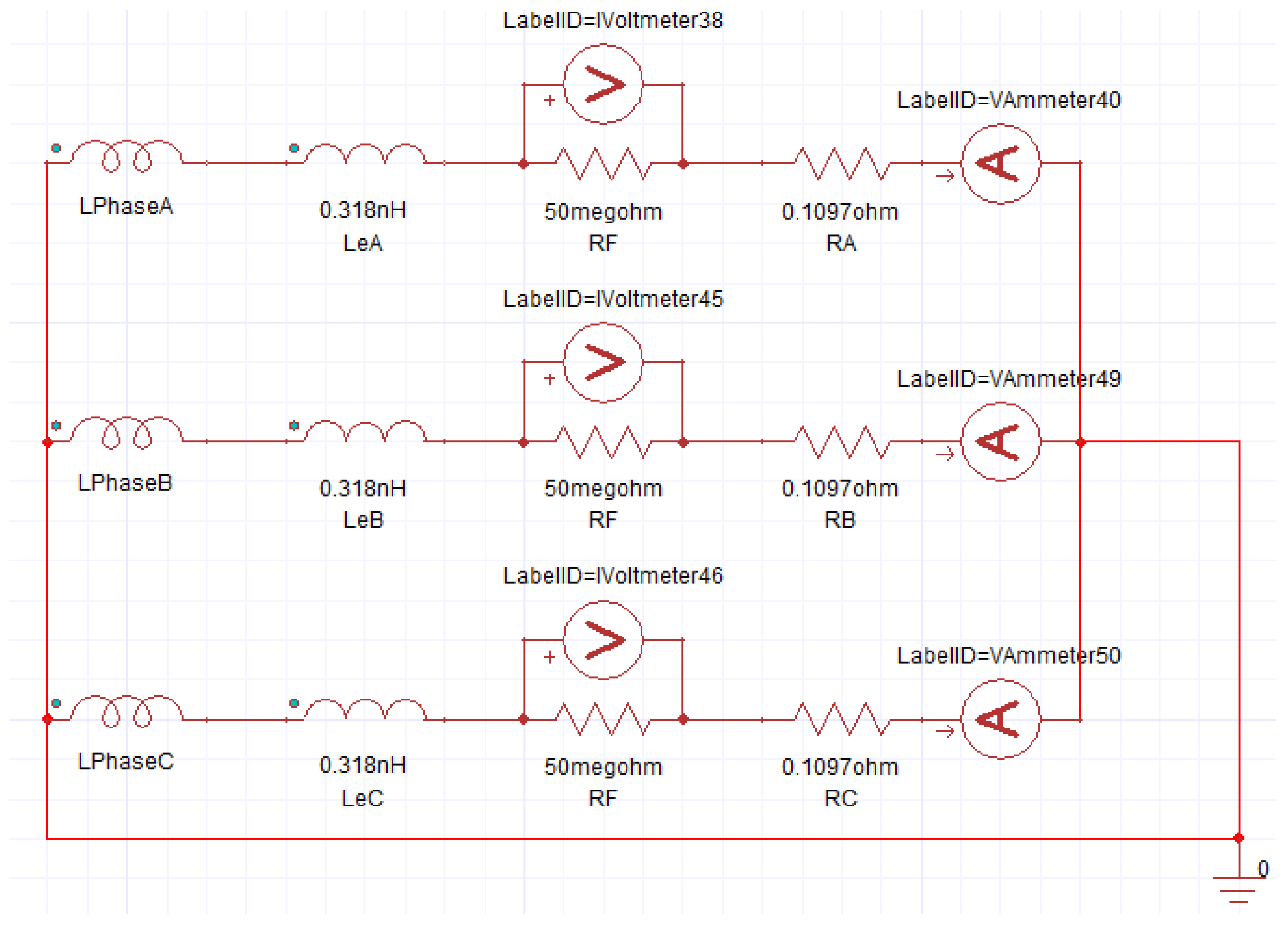
Figure 3.
Winding Copper Loss, Eddy Current Loss and Stator and Rotor Core Loss under rated load conditions.
Figure 3.
Winding Copper Loss, Eddy Current Loss and Stator and Rotor Core Loss under rated load conditions.
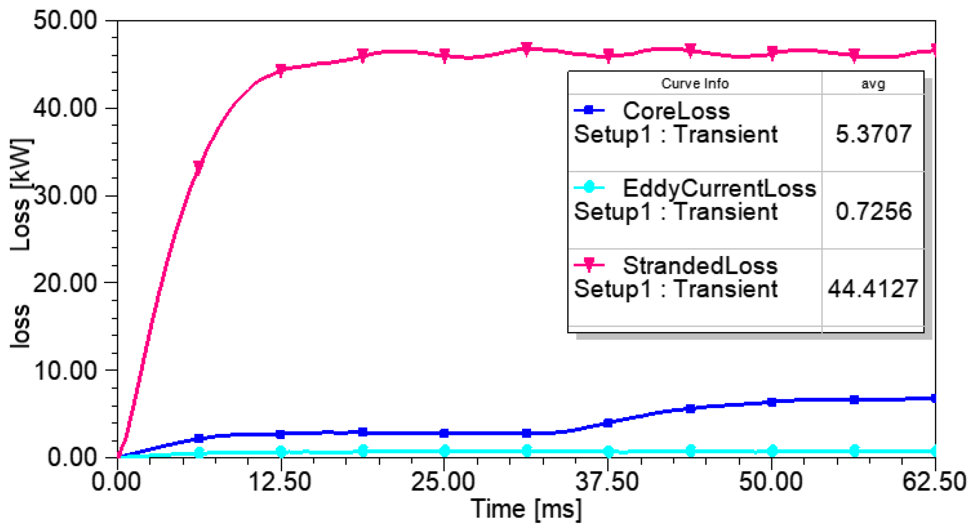
Figure 4.
Permanent magnet wind turbine three-phase short circuit external circuit.
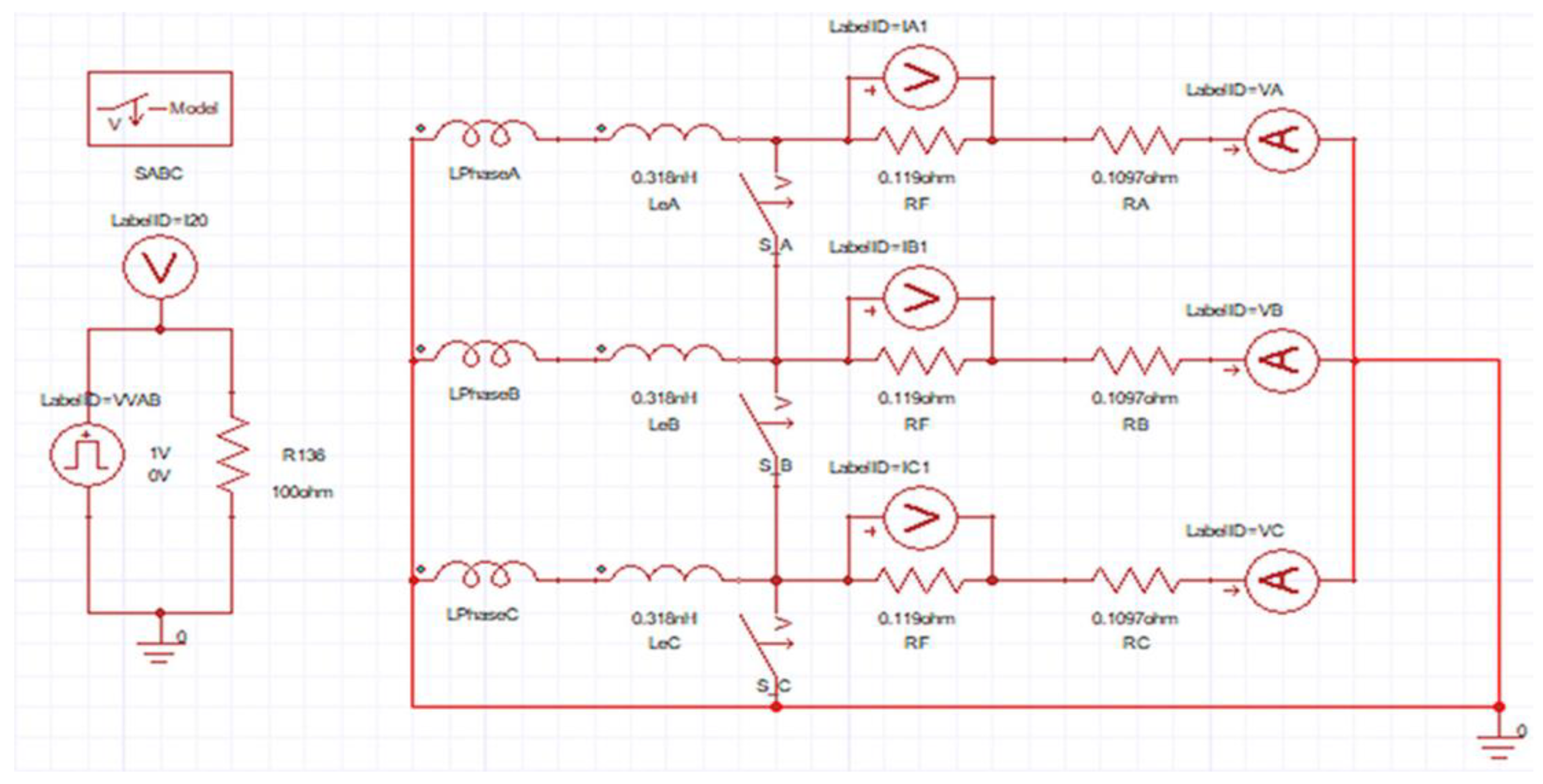
Figure 5.
Winding Copper Loss, Eddy Current Loss and Stator and Rotor Core Loss under three-phase short-circuit conditions.
Figure 5.
Winding Copper Loss, Eddy Current Loss and Stator and Rotor Core Loss under three-phase short-circuit conditions.
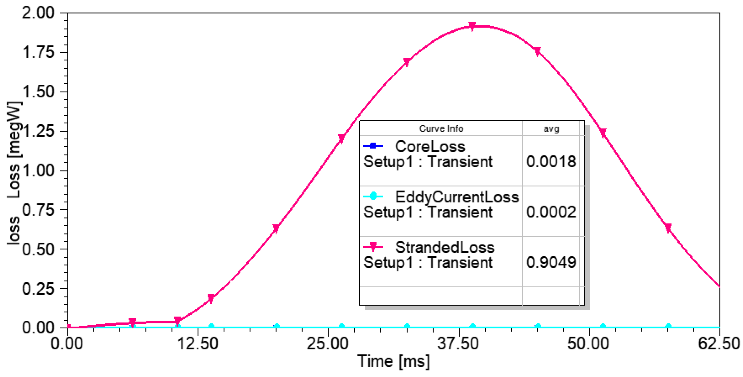
Figure 6.
Equivalent Simplified Model of Stator Slot Part.
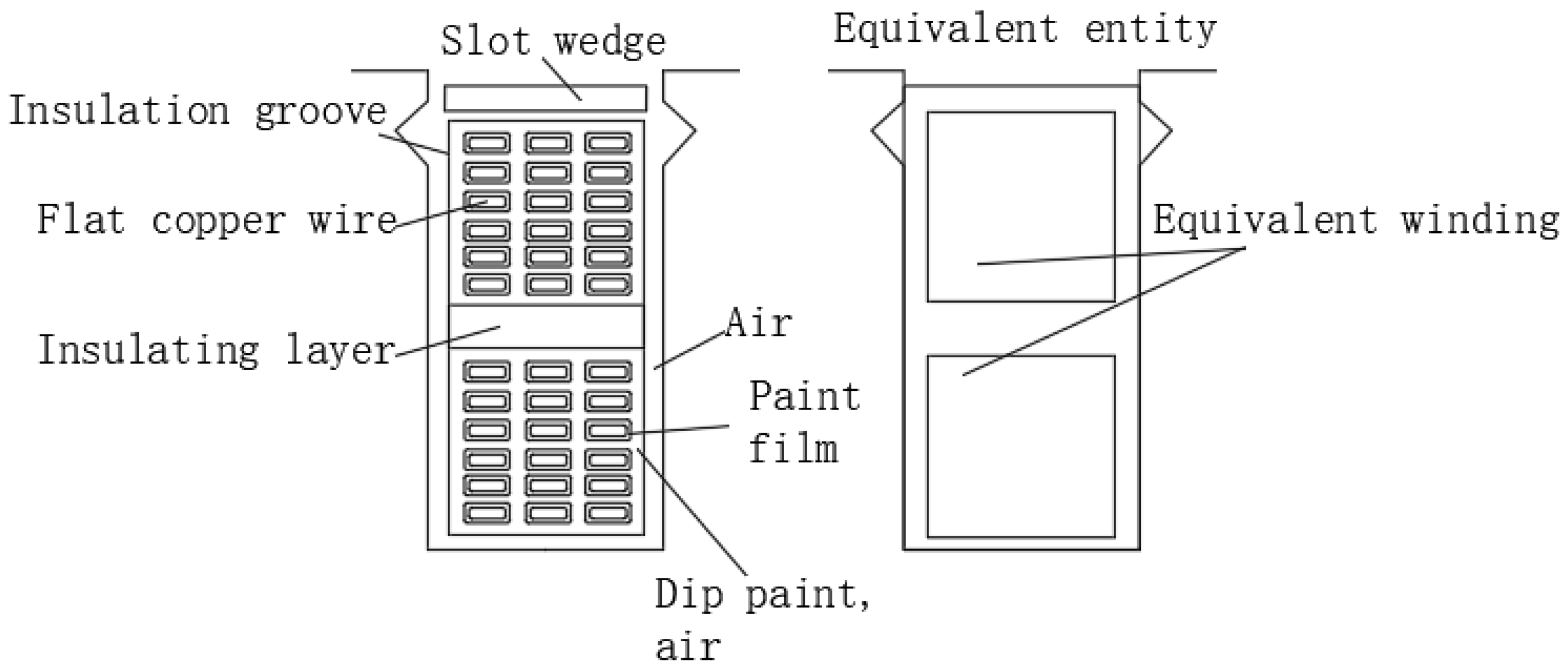
Figure 7.
Magnetic-thermal-flow field coupling simulation process.

Figure 8.
Meshing of the model.
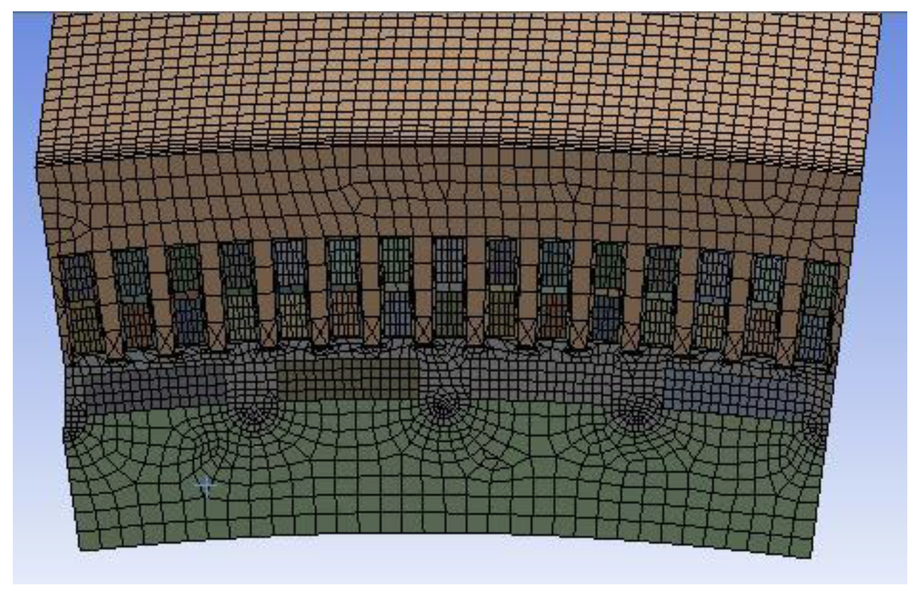
Figure 9.
(a) Schematic diagram of temperature distribution of wind turbine model, (b) schematic diagram of temperature distribution of rotor model, (c) schematic diagram of temperature distribution of stator model, (d) schematic diagram of temperature distribution of rotor model, and (e) schematic diagram of temperature of permanent magnet model.
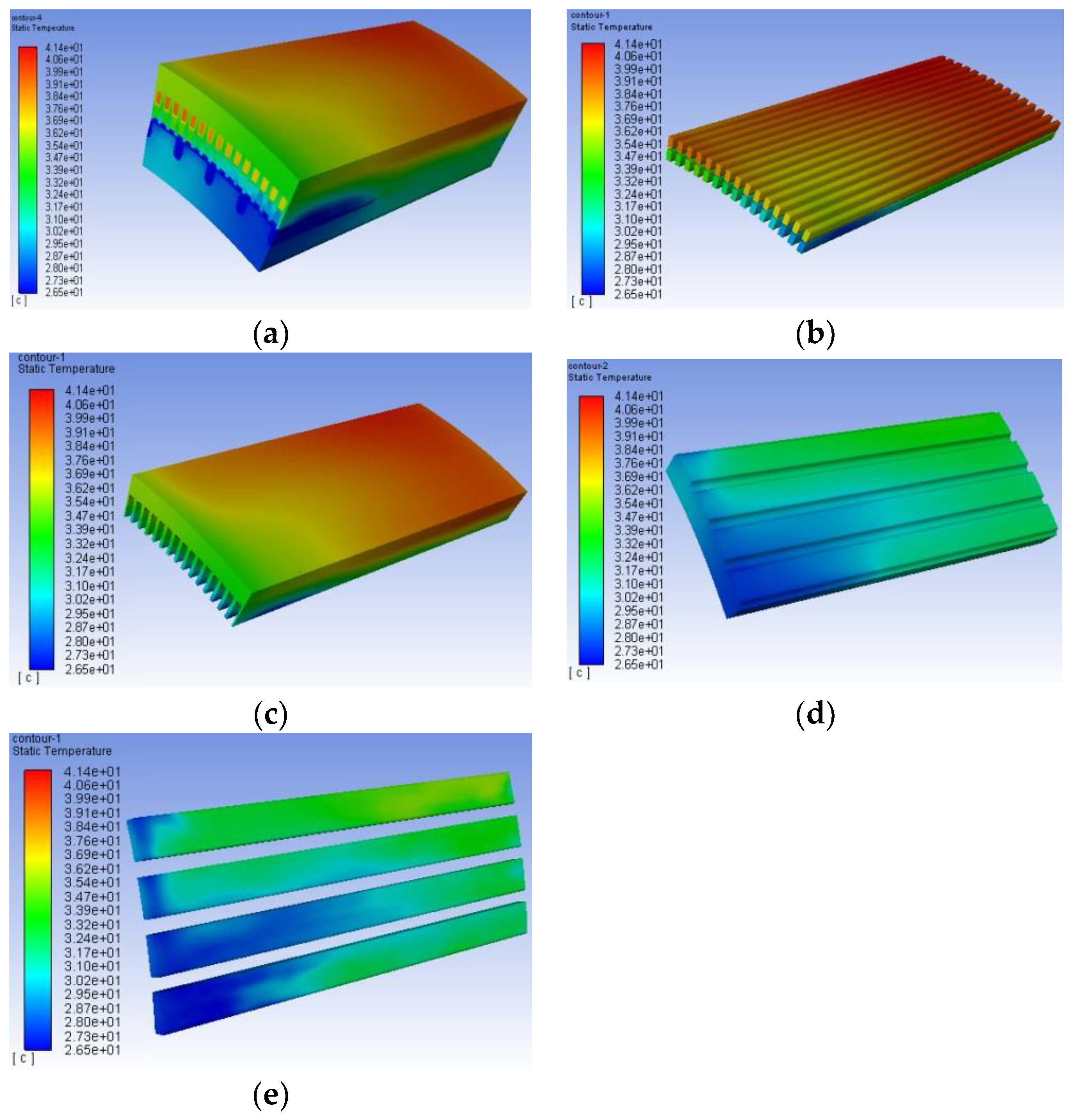
Figure 10.
(a) Schematic diagram of temperature distribution of wind turbine model, (b) schematic diagram of temperature distribution of winding model, (c) schematic diagram of temperature distribution of stator model, (d) schematic diagram of temperature distribution of rotor model, and (e) schematic diagram of temperature of permanent magnet model.
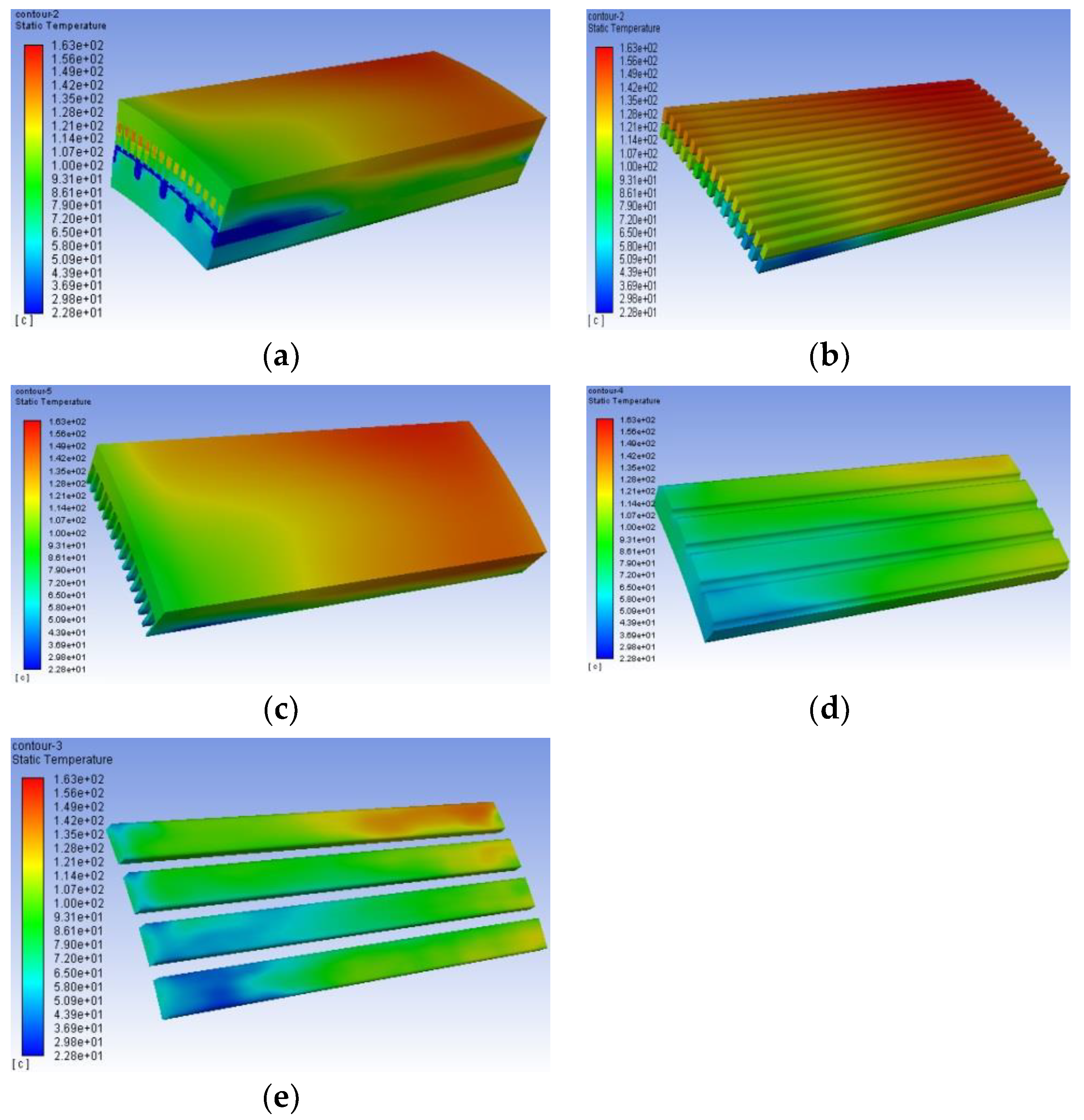
Figure 11.
Temperature of each component of the generator under rated load condition.

Figure 12.
The axial temperature of each component of the generator under three-phase short-circuit conditions.
Figure 12.
The axial temperature of each component of the generator under three-phase short-circuit conditions.

Figure 13.
Experimental testing and data collection platform.


Table 1.
Wind turbine model parameters.
| Parameter Name | Parameter Value | Parameter Name | Parameter Value |
|---|---|---|---|
| Power | 4 MW | Stator inner diameter | 4125 mm |
| Number of phases | 3 phases | Stator outer diameter | 4425 mm |
| Number of poles | 96 | Rotor inner diameter | 3910 mm |
| Rotate speed | 20 rpm | Rotor outer diameter | 4110 mm |
| Frequency | 16 Hz | Core length | 1480 mm |
| Voltage | 690 V | Parallel branch roads | 8 |
| Number of slots | 360 | Per slot conductor | 10 |
Table 2.
Materials and thermal influence parameters of various components of wind turbines.
| Parts | Material | Specific Heat Capacity/[J/(kg·°C) | Density/(kg/m3) | Thermal Conductivity/[W/(m·°C) |
|---|---|---|---|---|
| Stator | DW315-50 | 460 | 7800 | 42.5 |
| Rotor | DW315-50 | 460 | 7800 | 42.5 |
| Magnet | NdFe35 | 410 | 7400 | 8 |
| Rotating shaft | 42CrMoA | 461 | 7850 | 43.2 |
| Winding | Copper (equivalent) | 400 | 8954 | 400 |
| Air gap | air | 1006.43 | 1.225 | 0.0242 |
| Dipped paint | Dip paint | 1700 | 950 | 0.17 |
| IKnsulation | Slot insulation | 1000 | 1400 | 0.2 |
| Varnish film | Paint film | 1750 | 800 | 0.14 |
Table 3.
Thermal conductivity of each assembly gap.
| Part One | Part Two | Thermal Resistance Category | Thickness/mm | Density/(kg/m3) | Specific Heat Capacity/[J/(kg·°C) | Thermal Conductivity/[W/(m·°C) |
|---|---|---|---|---|---|---|
| Stator | Winding | Slot insulation | 0.4 | 1400 | 1000 | 0.16 |
| Stator | Rotor | Air | 1.3 | 1.225 | 1005 | - |
| Rotor | Shaft of rotation | Air | 0.01 | 1.225 | 1005 | 0.025 |
| Rotor | Permanent magnet | Air | 0.01 | 1.225 | 1.005 | 0.025 |
Table 4.
Heat dissipation coefficient of each part of the wind turbine.
| Various Parts of the Wind Turbine | Heat Dissipation Coefficient/[W/(K·m) |
|---|---|
| The outer surface of the stator | 15 |
| Stator ends | 60 |
| End windings | 68 |
| Rotor ends | 40 |
| Permanent magnet surface | 40 |
Table 5.
Comparison of experimental data and simulation data under rated load conditions.
| Temperature Measuring Element | Simulation Value/°C | Experimental Value/°C | Error/% |
|---|---|---|---|
| Component 1 | 28.14 | 27.34 | −2.93 |
| Component 2 | 29.17 | 29.84 | 2.25 |
| Component 3 | 30.34 | 31.21 | 2.79 |
| Component 4 | 31.56 | 32.51 | 2.92 |
| Component 5 | 33.14 | 33.97 | 2.44 |
| Component 6 | 35.72 | 34.58 | −3.30 |
| Component 7 | 37.69 | 37.23 | −1.24 |
| Component 8 | 38.77 | 39.18 | 1.05 |
| Component 9 | 37.46 | 38.53 | 2.78 |
| Component 10 | 37.35 | 36.82 | −1.44 |
| Component 11 | 36.13 | 35.36 | −2.18 |
Table 6.
Comparison of experimental data and simulation data under three-phase short-circuit conditions.
Table 6.
Comparison of experimental data and simulation data under three-phase short-circuit conditions.
| Temperature Measuring Element | Simulation Value/°C | Experimental Value/°C | Error/% |
|---|---|---|---|
| Component 1 | 65.33 | 63.84 | −2.33 |
| Component 2 | 80.26 | 78.35 | −2.44 |
| Component 3 | 93.17 | 96.67 | 3.62 |
| Component 4 | 112.64 | 110.98 | −1.50 |
| Component 5 | 126.89 | 129.13 | 1.73 |
| Component 6 | 136.47 | 138.71 | 1.61 |
| Component 7 | 143.54 | 148.68 | 3.46 |
| Component 8 | 158.76 | 161.23 | 1.53 |
| Component 9 | 148.92 | 152.38 | 2.27 |
| Component 10 | 139.57 | 136.18 | −2.49 |
| Component 11 | 130.24 | 127.88 | −1.85 |
Disclaimer/Publisher’s Note: The statements, opinions and data contained in all publications are solely those of the individual author(s) and contributor(s) and not of MDPI and/or the editor(s). MDPI and/or the editor(s) disclaim responsibility for any injury to people or property resulting from any ideas, methods, instructions or products referred to in the content. |
© 2023 by the authors. Licensee MDPI, Basel, Switzerland. This article is an open access article distributed under the terms and conditions of the Creative Commons Attribution (CC BY) license (https://creativecommons.org/licenses/by/4.0/).
Share and Cite
MDPI and ACS Style
Huang, Z.; Liu, Q.; Hao, Y. Research on Temperature Distribution of Large Permanent Magnet Synchronous Direct Drive Wind Turbine. Electronics 2023, 12, 2251. https://doi.org/10.3390/electronics12102251
AMA Style
Huang Z, Liu Q, Hao Y. Research on Temperature Distribution of Large Permanent Magnet Synchronous Direct Drive Wind Turbine. Electronics. 2023; 12(10):2251. https://doi.org/10.3390/electronics12102251
Chicago/Turabian StyleHuang, Zhengjun, Quan Liu, and Yuxin Hao. 2023. "Research on Temperature Distribution of Large Permanent Magnet Synchronous Direct Drive Wind Turbine" Electronics 12, no. 10: 2251. https://doi.org/10.3390/electronics12102251
Note that from the first issue of 2016, this journal uses article numbers instead of page numbers. See further details here.