
Experimental Evaluation of Predictive Torque Control of IPMSM under Speed Sensor and Sensorless Extended EMF Method

Department of Electrical and Computer Engineering, Ajou University, Suwon 16499, Republic of Korea
*
Author to whom correspondence should be addressed.
Electronics 2023, 12(1), 68; https://doi.org/10.3390/electronics12010068
Submission received: 14 November 2022
/
Revised: 20 December 2022
/
Accepted: 21 December 2022
/
Published: 24 December 2022
(This article belongs to the Special Issue Advanced Technologies in Power Electronics and Motor Drives)
Abstract
:This study investigates the impact of the position information on the torque performance for an interior permanent magnet synchronous motor (IPMSM) driven by finite set–predictive torque control (FS-PTC). Unlike induction machines, IPMSMs are significantly sensitive to the rotor position during the motor operation owing to the permanent magnet of the rotor. Any misalignment or displacement of the rotor frame (d-q) can lead to poor prediction of the motor drive performance because the predictive control requires speed/position information during the prediction and evaluation by the cost function. Hence, the performance of the FS-PTC, which uses a speed encoder and senseless extended electromotive force (EMF) estimation, is evaluated and compared with respect to the speed and load conditions. Based on the investigation, the sensorless FS-PTC using the EMF method has superior torque performance and THD reduction compared to the measured speed-based PTC, particularly under large load torque. The performance evaluation of IPMSM was carried out through experimental results.
1. Introduction
Unlike induction motors, permanent magnet synchronous motors (PMSMs) are made of a permanent magnet, and hence, do not depend on an external power source to generate the rotor flux. The construction design of PMSM results in distinct characteristics, such as high performance, high efficiency, and high power density compared to other AC motors [1,2,3,4,5]. These features have made the PMSMs an attractive choice for electric vehicles and other industrial applications.
In the past decades, several control strategies have been developed for PMSMs. Field-oriented control (FOC) and direct torque control (DTC) are considered to be the two most well-established control strategies for AC motors [6,7]. Compared with FOC, DTC has a simple principle with a fast dynamic torque response, yet it has the drawbacks of large torque ripples and a variable switching frequency [6]. Finite set–predictive torque control (FS-PTC) is one of the variations of DTC, which is a universally acceptable control method for PMSM [8] owing to its easy implementation, fast torque response, and the inclusion of constraints and nonlinearities [8,9,10,11,12]. In the traditional FS-PTC, a single voltage vector, which reduces the designed cost function, is chosen and applied in the next sampling period. The most prevalent challenge for FS-PTC is the tuning of the weighting factor because torque and flux errors are combined into a single cost function, which requires tuning a weighting factor to achieve the desired performance. There have been multiple studies on solving the weighting factor issue [12] because there exist various control objectives in the cost function that vary in magnitude. Hence, developing a cost function with multiple control objectives is tedious work, especially when applying trial-and-error methods [13,14]. To avoid this problem, weighting factor-free algorithms are applied [14]. For example, Ref. [15] employed an intelligent optimization algorithm based on particle swarm optimization. The authors of [16] proposed a sequential model of predictive torque control for two-level inverter-fed induction motor drives.
Conventional FS-PTC, which chooses one voltage vector for each control period, suffers from the problem of large torque ripples and distorted current [1,17]. To reduce the torque ripple of the FS-PTC algorithm, several control methods have been proposed. One of them is to use multilevel power circuits to obtain a large number of voltage vectors (VVs) [18], though special hardware design and more complicated control algorithms are needed. Another solution is to introduce virtual VVs [17], but this increases the motor-control complexity and raises the computation burden of the digital signal processor (DSP).
Accurate rotor positioning for PMSMs poses another challenge for FS-PTC, which can affect the system performance [19]. Mechanical sensors can have poor reliability. Additionally, the speed encoder and quantization error resolutions are likely to negatively impact the PMSM drive system. In order to increase the reliability, downsize the drive system, and reduce the system cost, the sensorless speed is applied to replace the speed sensor in motor drives. Sensorless motor control methods have been commercialized and widely used in industrial applications, such as robots, compressors, and electric vehicles [20]. Over the past decades, various state-estimation methods have been proposed to replace mechanical sensors. These methods can be grouped into saliency-based sensorless control and mathematical-model-based estimation methods [21,22]. The first category is suitable for situations in which the sensitivity of parameters is a crucial issue [23,24,25,26]. However, the estimation methods in the first category require either customized motors or well-designed filters. Moreover, these methods can be used to enable injected waveforms to create power losses and large torque ripples.
The mathematical-model-based estimation method depends on the machine model parameters at the fundamental frequency. Over the previous decades, various speed estimation techniques based on the fundamental model of the machine have emerged continuously, utilizing back electromotive force (back EMF) [27,28,29,30]. The back-EMF-based sensorless method has been widely used in various industries because of its simple algorithm, easy implementation, and robustness to disturbances. This category mainly requires the participation of an observer, which includes the sliding mode observer (SMO) [31,32,33], state observer [34], model adaptive method [35], and Kalman filter [36].
Most of the reported studies [27,28,29,30] use the measured speed signal as a benchmark for designing their speed observers. Therefore, they focus on minimizing the speed estimation error, which is obtained from the comparison between the estimated and the measured speed signals. Theoretically, this does not guarantee that the measured position/speed is reliable owing to mounting requirements, noise immunity, and degradation due to vibration and humidity [27,28]. Misalignment or displacement of the PMSM rotor frame (d-q) can lead to poor prediction of the motor drive performance of FS-PTC because the predictive torque control requires speed information during the prediction and evaluation by the cost function.
This paper is aimed at improving the steady-state performance of the IPMSM drives for different operating conditions. Many conditions and variables can affect the motor drive performance. The basic concept of this work is to determine the effect of the speed position (obtained from measured and estimated speed signals) on the state prediction and the cost function for torque-ripple reduction under various operating conditions. Based on the investigation, the sensorless FS-PTC using the EMF method shows better estimation for the PMSM rotor frame (d-q), resulting in a superior torque and THD reduction compared to the measured speed-based PTC, particularly under high-load torque. The feasibility of the proposed method was validated using the experimental results.
2. Mathematical Model of IPMSM
Figure 1a shows the ideal phasor diagram of the IPMSM, which consists of three main coordinate axes. α-β, d-q, and γ-δ are the stationary frame, rotating reference frame synchronized to the rotor flux, and rotating reference synchronized with the estimated rotor position using the extended EMF method, respectively.
The mathematical model of the IPMSM is given in terms of complex vectors [3,9], which are expressed in a stationary reference frame as follows
where is the stator voltage; is the stator current, Rs is the stator resistance, is the stator flux linkage, is the permanent magnet flux linkage, Pn is the number of pole pairs, and Te is the electrical torque. Ls represents self-inductance.
3. Proposed Sensorless EEMF-PTC
In this section, we describe the EEMF model and the estimation process of the speed along with the integration of the estimated position and speed with the FS-PTC. This study aims to investigate the FS-PTC performance using the measured and estimated speed information.
3.1. Impact of Speed on the Torque Variation
The weighting factor is well known to play a crucial role in the FS-PTC performance [8]. In addition to the weighting factor, torque variation is an important component that affects the PTC performance. Generally, the torque derivative for the PMSM is expressed by [7]:
where denotes the rotor speed. From (4), the wrong speed information can affect the instantaneous torque and performance of other variables in the PTC control system. This is because the position and speed information are part of the flux estimation and the flux and torque prediction process in the FS-PTC.
The rotating frames shown in Figure 1a represent an ideal control system. Nevertheless, in a practical implementation, the estimated variables significantly vary under various operating conditions, resulting in the displacement of the rotating frames. The rotating d-q frame synchronized with the rotor flux of the permanent magnet significantly affects the estimation performance. This rotating frame can be obtained from either the measured position (), denoted by (), or the estimated position (), and it can be differentiated as (), as shown in Figure 1b. Unfortunately, errors in the measurement of the shaft angle cause displacement for () of the PMSM owing to the delay in encoder resolution and signal. Therefore, the estimated position can provide a more accurate rotating frame if the observer is well-designed. Consequently, this can improve the control system‘s performance.
The angular displacement between the dest and dmeas () can result in a poor prediction of the torque by reducing the chance of optimum VV selection.
3.2. Extended EMF Method
A sensorless extended EMF is normally applied for the medium- and high-speed operation of IPMSMs owing to its simple calculation and can be easily applied with less complexity, considering the direct proportionality between the EMF and the rotor speed [37,38,39].
Based on the rotating frame of the d-q axes, the voltage equation of an IPMSM using the extended EMF is defined as [37]:
where is the current in the rotating frame. Ld and Lq are the inductances along the rotating d-q frame. eMF represents the extended back EMF on the d-q frame and is expressed as
Hence, the voltage equation in the γ-δ rotating frame can be described as
where eγ and eδ are the induced voltages (extended EMF voltages) on the γ-δ rotating frame, which can be expressed as
where is the speed estimated by the extended EMF method. If the difference between the estimated speed, , and the actual speed, ωr, is negligible, the estimated EEMF voltages can be described as
From (10), the error in the estimated position can be expressed using the extended EMF voltages as follows:
The resultant error value of is used to obtain the estimated rotor speed by applying a proportional-integral (PI) control method as follows:
The PI speed estimation gains are designed using the damping coefficient, ζ and natural angular frequency, ωn, as follows [2]:
It is necessary to use a low-pass filter to reduce the noise impact and to ensure motor stability before it is applied for motor control as expressed by:
where is the cut-off frequency. Then, the motor position can be computed using (14).
Figure 2 shows a block diagram of the position and speed estimation algorithm based on the extended EMF observer.
3.3. Sensorless EEMF-PTC Method
The next stage is to discretize the continuous Equations (1)–(3). In the PTC of IPMSMs, the discretized stator flux linkage ψs(k), and the electrical torque Te, are estimated as follows:
where is the rotor flux linkage considering the estimated position.
The predicted stator flux linkage can be obtained by evaluating all the possible voltage vectors {v0, v1,…,v7} of the two-level voltage source inverter (2L-VSI) as shown in Figure 3 and utilizing the estimated speed from the extended EMF stage, as follows:
and the predicted stator current is obtained as:
where
Based on the predicted values of the stator flux and torque, the electromagnetic torque can be predicted as follows:
where Wψ is the weighting factor that defines the relative significance of the flux control objective. In this study, Wψ is considered the ratio of the rated torque and flux (Trated/ψrated). Tref and ψref are the torque and flux linkage references at the kth sampling time, respectively. The application of vs is based on the selection of optimized switching states (Sa, Sb, Sc) for 2L-VSI from the cost function optimal VV, vopt. The stator voltage vectors in terms of the switching states can be described as
where VDC is the direct current (DC) link voltage.
It is worth noting that the same procedure can be applied to conventional PTC but with considering the speed information obtained from the speed encoder. Figure 4 shows the block diagram of the proposed PTC that depicts how the transition happens between estimated and measured speed/position.
4. Implementation and Experimental Results
The performance of the sensorless extended EMF-based PTC and traditional PTC methods for a 2L-VSI-fed IPMSM coupled with an induction machine (load) was experimentally implemented using a functional DSP (TMS320C28335). The experimental setup is illustrated in Figure 5. The specifications of the machine parameters are listed in Table 1. The nominal flux and weighting factor were set at 0.58 Wb and 150, respectively. A DC-link voltage of 300 V was supplied.
To investigate the performance of the proposed sensorless extended EMF-based PTC method, it was compared with the traditional PTC fed by the measured speed at different motor operations under the same weighting factor and operating conditions. For ease of identification, traditional FS-PTC and sensorless extended EMF-based PTC are abbreviated to CPTC and EEMF-PTC, respectively. Notably, the difference between both PTC methods is achieved by changing the speed and position online for the measured and estimated speeds during the operation of the motor. The switching operation between the two methods is shown in Figure 4.
Figure 6 shows the steady-state performance of both the PTC methods at 200 rpm under: (1) no-load and (2) 20 Nm load torque. The figure is divided into two parts: the CPTC and EEMF-PTC. From top to bottom, the curves shown in Figure 6 are the electrical torque, estimated position, measured position, and A-phase output current, ia. Notably, the rotor position is used for the rotor frame calculation, which is then applied for the estimation and prediction of the flux and torque values, as previously mentioned. The torque ripples were calculated online using the equation [9]. Figure 6a shows that, under the no-load condition, the proposed PTC has managed to reduce the torque ripple by 13 %, while maintaining the current waveform unchanged for both the PTC algorithms. Nevertheless, when the load torque was applied at 20 Nm for the same speed as shown in Figure 6b, the torque ripple was further reduced by 32% and the current spikes were clearly reduced. This indicates that, under heavy loads, the measured position becomes less accurate, which leads to the selection of undesired VVs, and hence, results in poor torque prediction. For clearer illustration in Figure 6, the highlighted positions (i.e., measured and estimated) under no-load and load conditions are zoomed as shown in Figure 7. By inspecting the position error (), it is apparent that the error is larger when the load is applied as shown in Figure 7b. This is mainly the reason for the increase in the torque ripple at high load when the measured speed is used in PTC control as previously mentioned. As the EEMF-PTC shows better reduction in the torque ripple, this indicates the EEMF estimated position/speed has better alignment with the rotor, and hence, it is more accurate than the measured position/speed for the motor drive.
Figure 8 shows the steady-state performance of both PTC methods at 600 rpm, with and without a load torque. The proposed and conventional PTC methods show comparable torque ripple values at a no-load condition. Nevertheless, the proposed method displays a 23% reduction in terms of torque ripples when a load is applied, as shown in Figure 8b. Once again, there is no change in either algorithm, except for speed/position. This implies that speed and position play a crucial role in the torque slopes and accuracy of the prediction stage for the PTC algorithms.
The FFT waveforms of the stator current for the two PTC methods under the load torque operation are shown in Figure 6b and Figure 8b, which are presented in Figure 9 and Figure 10, respectively. The proposed PTC (EEMF-PTC) exhibits the best performance in terms of total harmonic distortion (THD) reduction. It can be deduced that the accuracy of the speed position significantly influences the THD compared to the torque ripple. It is apparent that the THD is quite high due to the large power rating of controlled IPMSMs and finite number of voltage vectors (two passive and six active voltage vectors).
For the result summary (i.e., from Figure 6, Figure 8, Figure 9 and Figure 10), the quantitative comparison of the steady-state performance of the torque ripple and current THD is shown in Table 2. It can be seen that the torque ripple and current THD in EEMF-PTC methods are much smaller than those in CMPC for both speed and load conditions, especially when a large load torque is applied. This confirms the effectiveness of our analysis that the speed information has a critical impact on motor control.
Finally, Figure 11 depicts the responses of measured speed, estimated speed, and speed-error () waveforms for the CPTC and EEMF-PTC during the slow-speed operation. The speed error is the comparison between measured and estimated speeds, as defined by
The motor speed changes slowly from 300 rpm to 900 rpm. Although both methods have a smooth transition between 300 rpm and 900 rpm and maintain a small error band, each method has different speed error profile. It can be observed that the speed error for the EEMF-PTC is slightly smaller in high-speed regions owing to the higher accuracy of the d-q frame.
5. Conclusions
In this study, a senseless FS-PTC algorithm using an extended EMF was presented to improve the performance of a 2 L-VSI-driven IPMSM. Since speed is an essential part of an IPMSM-driven system, this study evaluated the performance of FS-PTC under measured and estimated speeds. According to the experimental results, the sensorless FS-PTC using the extended EMF method has a superior torque performance and THD reduction compared to the measured speed-based PTC, particularly under high-load torques. Moreover, it can also be found that the dq-rotor frame can be displaced owing to the encoder delay, resulting in poor torque prediction and, hence, increasing the torque ripple and current distortion.
Additionally, the speed error showed fewer oscillations in the high-speed region when the position and speed of the EEMF method are applied in PTC. This can be attributed to the dq-rotor frame accuracy with EEMF estimation at high speed.
Author Contributions
Conceptualization and writing—original draft preparation, methodology, validation, and formal analysis, I.M.A.; resources, and writing—review and editing, S.A.Q.M. and I.M.A. All authors have read and agreed to the published version of the manuscript.
Funding
This research received no external funding.
Data Availability Statement
Not applicable.
Acknowledgments
Special thanks go to Kyo-Beum Lee for permission to use the Power Electronics Equipment.
Conflicts of Interest
The authors declare no conflict of interest.
References
- Alsofyani, I.M.; Lee, K.-B. Predictive Torque Control Based on Discrete Space Vector Modulation of PMSM without Flux Error-Sign and Voltage-Vector Lookup Table. Electronics 2020, 9, 1542. [Google Scholar] [CrossRef]
- Seo, D.-W.; Bak, Y.; Lee, K.-B. An improved rotating restart method for a sensorless permanent magnet synchronous motor drive system using repetitive zero voltage vectors. IEEE Trans. Ind. Electron. 2020, 67, 3496–3504. [Google Scholar] [CrossRef]
- Cho, Y.; Lee, K.-B.; Song, J.-H.; Lee, Y.I. Torque-ripple minimization and fast dynamic scheme for torque predictive control of permanent-magnet synchronous motors. IEEE Trans. Power Electron. 2015, 30, 2182–2190. [Google Scholar] [CrossRef]
- Bak, Y.; Lee, K.-B. Constant speed control of a permanent-magnet synchronous motor using a reverse matrix converter under variable generator input conditions. IEEE J. Emerg. Sel. Top. Power Electron. 2018, 6, 315–326. [Google Scholar] [CrossRef]
- Zhu, Y.; Tao, B.; Xiao, M.; Yang, G.; Zhang, X.; Lu, K. Luenberger Position Observer Based on Deadbeat-Current Predictive Control for Sensorless PMSM. Electronics 2020, 9, 1325. [Google Scholar] [CrossRef]
- Elgbaily, M.; Anayi, F.; Alshbib, M.M. A Combined Control Scheme of Direct Torque Control and Field-Oriented Control Algorithms for Three-Phase Induction Motor: Experimental Validation. Mathematics 2022, 10, 3842. [Google Scholar] [CrossRef]
- Alsofyani, I.M.; Lee, K. Enhanced Performance of Constant Frequency Torque Controller–Based Direct Torque Control of Induction Machines with Increased Torque-Loop Bandwidth. IEEE Trans. Ind. Electron. 2020, 67, 10168–10179. [Google Scholar] [CrossRef]
- Vazquez, S.; Rodriguez, J.; Rivera, M.; Franquelo, L.G.; Norambuena, M. Model predictive control for power converters and drives: Advances and trends. IEEE Trans. Ind. Electron. 2017, 64, 935–947. [Google Scholar] [CrossRef] [Green Version]
- Alsofyani, I.M.; Lee, K.B. A Uni-Directional Voltage Vector Preselection Strategy for Optimizing Model Predictive Torque Control with Discrete Space Vector Modulation of IPMSM. IEEE Trans. Ind. Electron. 2022, 69, 12305–12315. [Google Scholar] [CrossRef]
- Xu, Y.; Sun, Y.; Hou, Y. Multi-step model predictive current control of permanent-magnet synchronous motor. J. Power Electron. 2020, 20, 176–187. [Google Scholar] [CrossRef]
- Fan, S.; Tong, C. Model predictive current control method for PMSM drives based on an improved prediction model. J. Power Electron. 2020, 20, 1456–1466. [Google Scholar] [CrossRef]
- Vazquez, S.; Leon, J.I.; Franquelo, L.G.; Rodriguez, J.; Young, H.A.; Marquez, A.; Zanchetta, P. Model predictive control: A review of its applications in power electronics. IEEE Ind. Electron. Mag. 2014, 8, 16–31. [Google Scholar] [CrossRef]
- Cortes, P.; Kouro, S.; La Rocca, B.; Vargas, R.; Rodriguez, J.; Leon, J.I.; Vazquez, S.; Franquelo, L.G. Guidelines for weighting factors design in model predictive control of power converters and drives. In Proceedings of the 2009 IEEE International Conference on Industrial Technology, Churchill, Australia, 10–13 February 2009; pp. 1–7. [Google Scholar]
- Shadmand, M.B.; Balog, R.S.; Rub, H.A. Auto-tuning the cost function weight factors in a model predictive controller for a matrix converter VAR compensator. In Proceedings of the 2015 IEEE Energy Conversion Congress and Exposition, Montreal, QC, Canada, 20–24 September 2015; pp. 3807–3814. [Google Scholar]
- Fretes, H.; Rodas, J.; Doval-Gandoy, J.; Gomez, V.; Gomez, N.; Novak, M.; Rodriguez, J.; Dragičević, T. Pareto Optimal Weighting Factor Design of Predictive Current Controller of a Six-Phase Induction Machine Based on Particle Swarm Optimization Algorithm. IEEE J. Emerg. Sel. Top. Power Electron. 2022, 10, 207–219. [Google Scholar] [CrossRef]
- Norambuena, M.; Rodriguez, J.; Zhang, Z.; Wang, F.; Garcia, C.; Kennel, R. A very simple strategy for high-quality performance of AC machines using model predictive control. IEEE Trans. Power Electron. 2019, 34, 794–800. [Google Scholar] [CrossRef]
- Alsofyani, I.M.; Bak, Y.; Lee, K.-B. Improved Finite Set-Predictive Torque Control of PMSM Fed by Indirect Matrix Converter with Discrete Space Vector Modulation. Electronics 2020, 9, 2133. [Google Scholar] [CrossRef]
- Zouari, W.; El Badsi, I.N.; El Badsi, B.; Masmoudi, A. Three-Level NPC Inverter-Fed IM Drives under PTC, Minimizing the Involved Voltage Vectors and Balancing the DC Bus Capacitor Voltages. Sustainability 2022, 14, 13522. [Google Scholar] [CrossRef]
- Alaei, A.; Lee, D.-H.; Ahn, J.-W.; Nejad, S.M.S. Sensorless control of IPMSM with a simplified high- frequency square wave injection method. J. Electr. Eng. Technol. 2018, 13, 1515–1527. [Google Scholar]
- Motor Control: Efficient, Flexible and Secure. Available online: https://www.nxp.com/applications/enabling-technologies/motor-control:MOTOR-CONTROL (accessed on 12 December 2022).
- Yongsoon, P.; Seung-Ki, S. Sensorless control method for PMSM based on frequency-adaptive disturbance observer. IEEE J. Emerg. Sel. Top. Power Electron. 2014, 2, 143–151. [Google Scholar] [CrossRef]
- Teja, A.V.R.; Chakraborty, C.; Maiti, S.; Hori, Y. A new model reference adaptive controller for four quadrant vector controlled induction motor drives. IEEE Trans. Ind. Electron. 2012, 59, 3757–3767. [Google Scholar] [CrossRef]
- Yin, Z.G.; Zhao, C.; Zhong, Y.R.; Liu, J. Research on robust performance of speed-sensorless vector control for the induction motor using an interfacing multiple-model extended Kalman filter. IEEE Trans. Power Electron. 2014, 29, 3011–3019. [Google Scholar] [CrossRef]
- Han, D.-Y.; Cho, Y.; Lee, K.-B. Simple sensorless control of interior permanent magnet synchronous motor using PLL based on extended EMF. J. Electr. Eng. Technol. 2017, 12, 711–717. [Google Scholar] [CrossRef]
- Chi, S.; Zhang, Z.; Xu, L. Sliding-mode sensorless control of directdrive PM synchronous motors for washing machine applications. IEEE Trans. Ind. Appl. 2009, 45, 582–590. [Google Scholar] [CrossRef]
- Woldegiorgis, A.T.; Ge, X.; Wang, H.; Hassan, M. A New Frequency Adaptive Second-Order Disturbance Observer for Sensorless Vector Control of Interior Permanent Magnet Synchronous Motor. IEEE Trans. Ind. Electron. 2021, 68, 11847–11857. [Google Scholar] [CrossRef]
- Özkurt, G.; Zerdali, E. Design and Implementation of Hybrid Adaptive Extended Kalman Filter for State Estimation of Induction Motor. IEEE Trans. Instrum. Meas. 2022, 71, 1–12. [Google Scholar] [CrossRef]
- Wang, G.; Valla, M.; Solsona, J. Position sensorless permanent magnet synchronous machine drives—A review. IEEE Trans. Ind. Electron. 2020, 67, 5830–5842. [Google Scholar] [CrossRef]
- Wang, S.; Yang, K.; Chen, K. An improved position-sensorless control method at low speed for PMSM based on high-frequency signal injection into a rotating reference frame. IEEE Access 2019, 7, 86510–86521. [Google Scholar] [CrossRef]
- Yoon, T.-M.; Lee, J.-S.; Lee, K.-B. Rotor position estimation method of IPMSM using HF signal injection and sliding-mode controller. IEEJ Trans. Electr. Electron. Eng. 2014, 9, S56–S63. [Google Scholar] [CrossRef]
- Kim, S.; Ha, J.-I.; Sul, S.-K. PWM switching frequency signal injection sensorless method in IPMSM. IEEE Trans. Ind. Appl. 2012, 48, 1576–1587. [Google Scholar] [CrossRef]
- Wang, G.; Li, Z.; Zhang, G.; Yu, Y.; Xu, D. Quadrature PLL-based highorder sliding–mode observer for IPMSM sensorless control with online MTPA control strategy. IEEE Trans. Energy Convers. 2013, 28, 214–224. [Google Scholar] [CrossRef]
- Fan, Y.; Zhang, L.; Cheng, M.; Chau, K.T. Sensorless SVPWMFADTC of a new flux-modulated permanent-magnet wheel motor based on a wide-speed sliding mode observer. IEEE Trans. Ind. Electron. 2015, 62, 3143–3151. [Google Scholar] [CrossRef] [Green Version]
- Liu, J.M.; Zhu, Z.Q. Improved sensorless control of permanent magnet synchronous machine based on third-harmonic back EMF. IEEE Trans. Ind. Appl. 2014, 50, 1861–1870. [Google Scholar] [CrossRef]
- Smith, A.; Gadoue, S.; Finch, J. Improved rotor flux estimation at low speeds for torque MRAS-based sensorless induction motor drives. IEEE Trans. Energy Convers. 2016, 31, 270–282. [Google Scholar] [CrossRef] [Green Version]
- Zerdali, E. Adaptive Extended Kalman Filter for Speed-Sensorless Control of Induction Motors. IEEE Trans. Energy Convers. 2019, 34, 789–800. [Google Scholar] [CrossRef]
- Zhong, Z.; Zhou, S.; Shao, Z. Multiple reference frame-based current harmonic control for interior PMSMs considering motional EMF. J. Power Electron. 2021, 21, 921–931. [Google Scholar] [CrossRef]
- Lee, H.; Cho, D.; Lee, K. Rotor position estimation over entire speed range of interior permanent magnet synchronous motors. J. Power Electron. 2021, 21, 693–702. [Google Scholar] [CrossRef]
- Morimoto, S.; Kawamoto, K.; Sanada, M.; Takeda, Y. Sensorless control strategy for salient-pole PMSM based on extended EMF in rotating reference frame. IEEE Trans. Ind. Appl. 2002, 38, 1054–1061. [Google Scholar] [CrossRef]
Figure 1.
IPMSM System with (a) ideal coordinates and (b) misaligned coordinates.

Figure 2.
Schematic diagram for the estimation process of position and speed based on extended EMF.
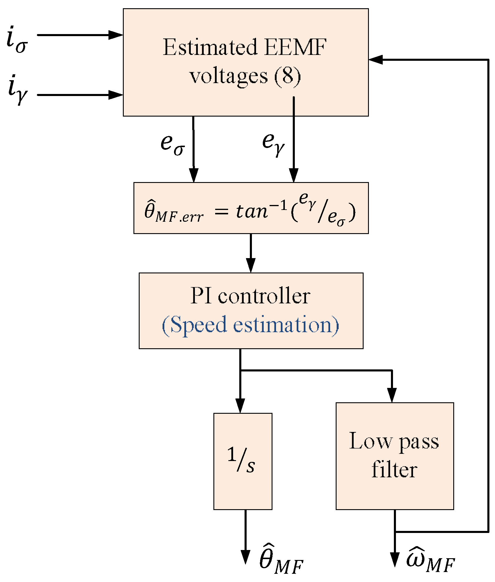
Figure 3.
Space vector diagram for 2L-VSI.
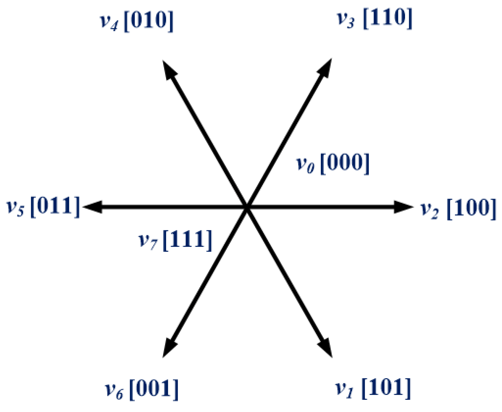
Figure 4.
Proposed block diagram for the PTC with speed sensor and sensorless extended EMF.
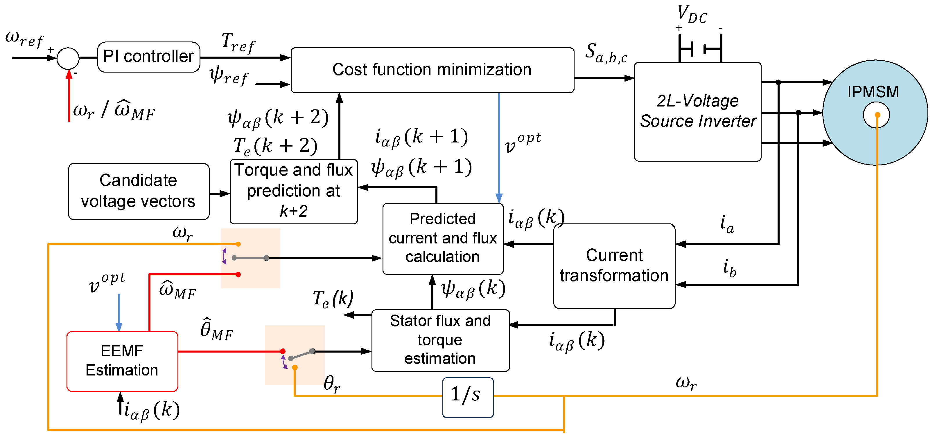
Figure 5.
Experimental setup.
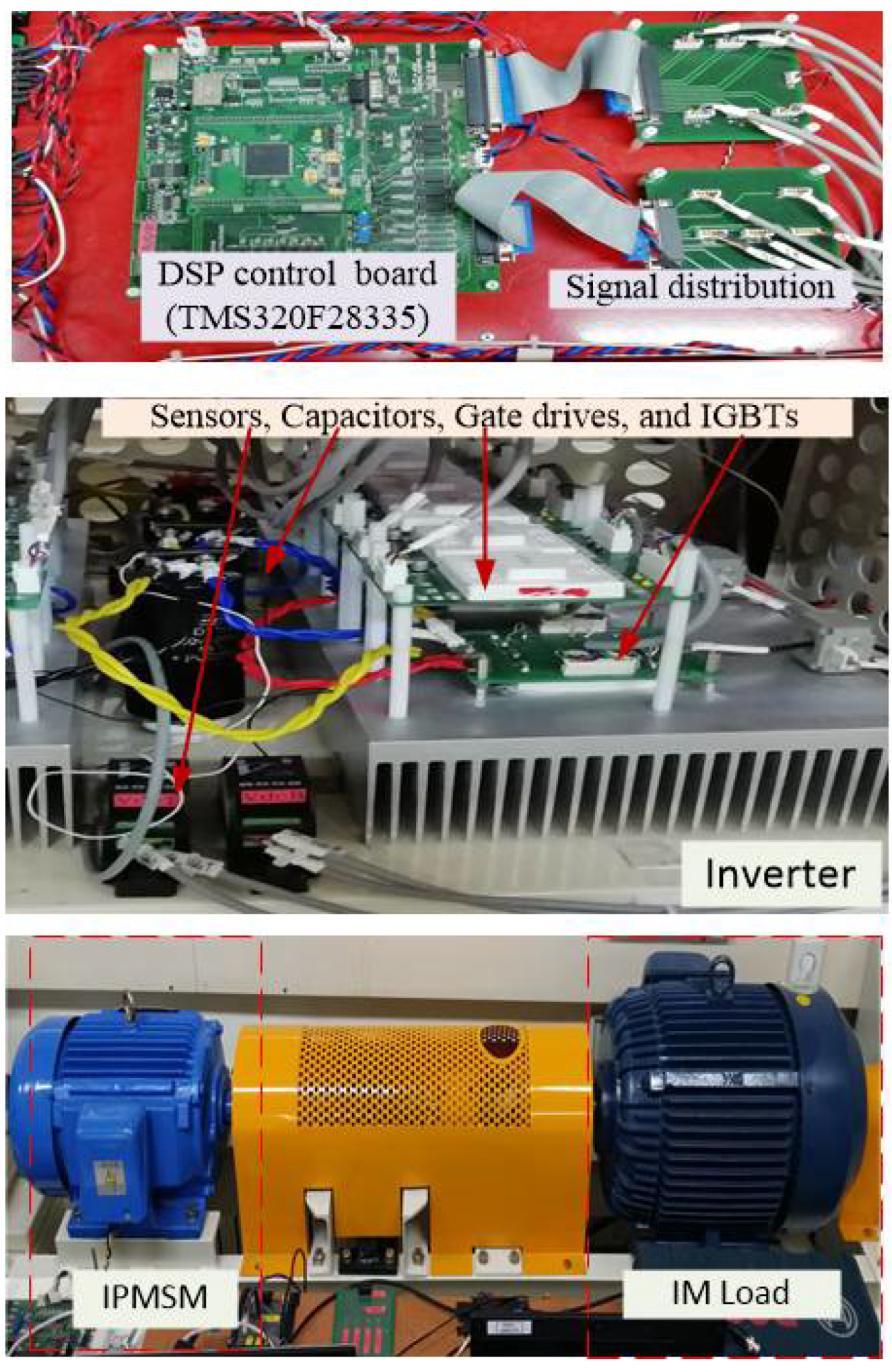
Figure 6.
Experimental steady-state response at 200 rpm for PTC with speed sensor and sensorless EMF methods under (a) no load and (b) load torque.
Figure 6.
Experimental steady-state response at 200 rpm for PTC with speed sensor and sensorless EMF methods under (a) no load and (b) load torque.

Figure 7.
Zoomed images for estimated position and measured position in Figure 6: (a) 0 Nm and (b) 20 Nm.
Figure 7.
Zoomed images for estimated position and measured position in Figure 6: (a) 0 Nm and (b) 20 Nm.
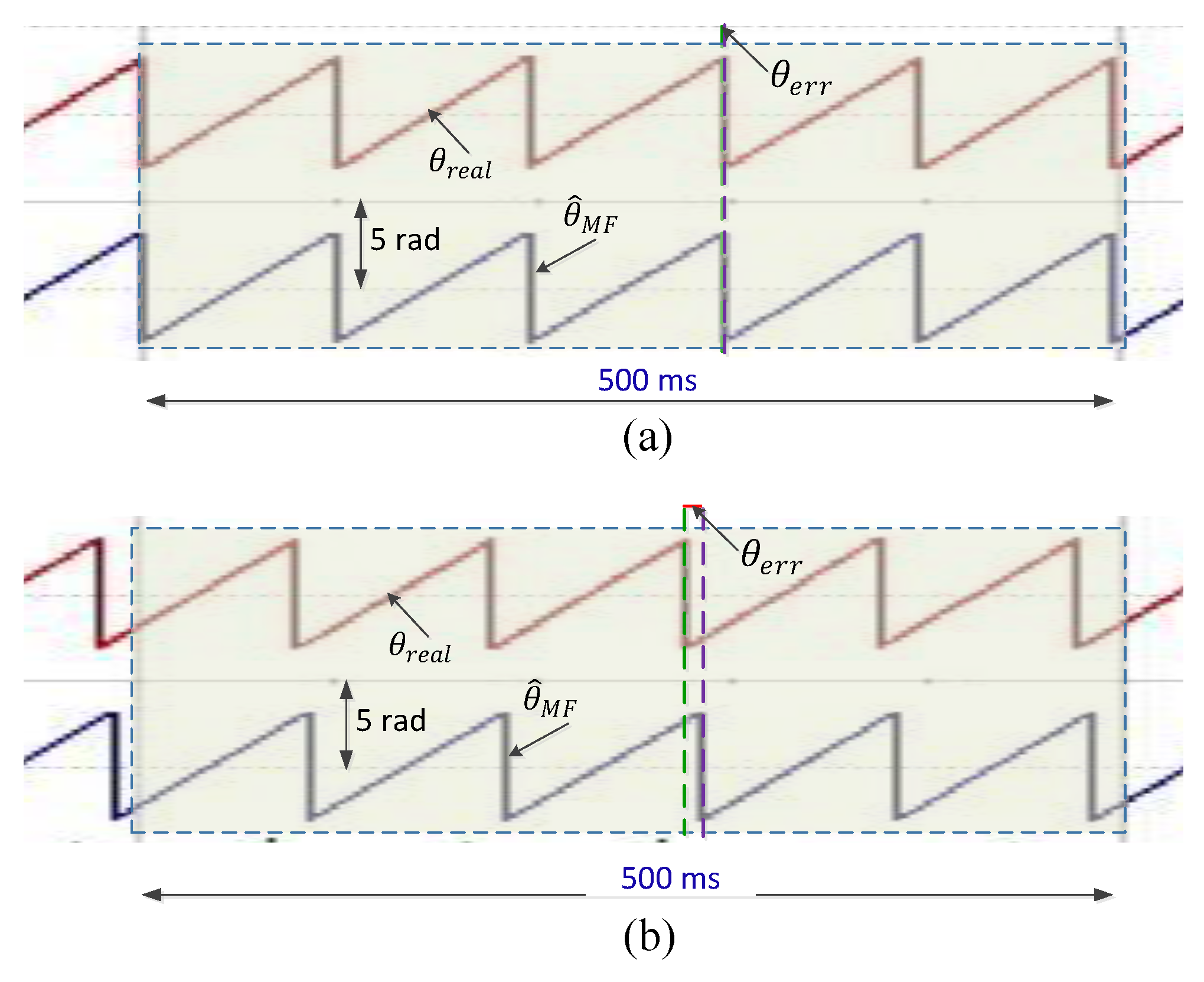
Figure 8.
Experimental steady-state response at 600 rpm for PTC with speed sensor and sensorless EMF methods under (a) no load and (b) load torque.
Figure 8.
Experimental steady-state response at 600 rpm for PTC with speed sensor and sensorless EMF methods under (a) no load and (b) load torque.
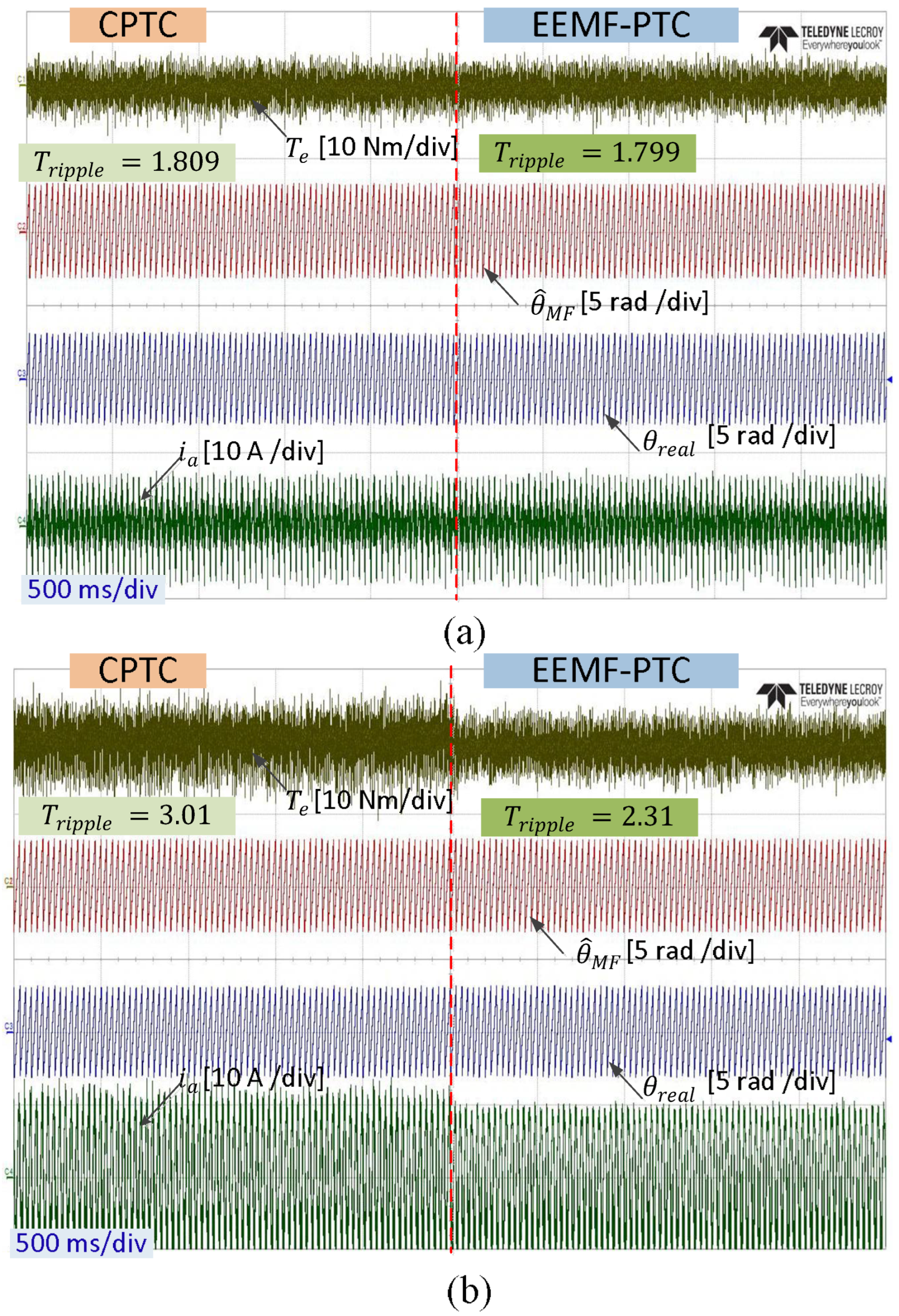
Figure 9.
Experimental frequency spectra of A-phase motor current at 200 rpm under load torque for (a) CPTC and (b) EEMF-PTC.
Figure 9.
Experimental frequency spectra of A-phase motor current at 200 rpm under load torque for (a) CPTC and (b) EEMF-PTC.
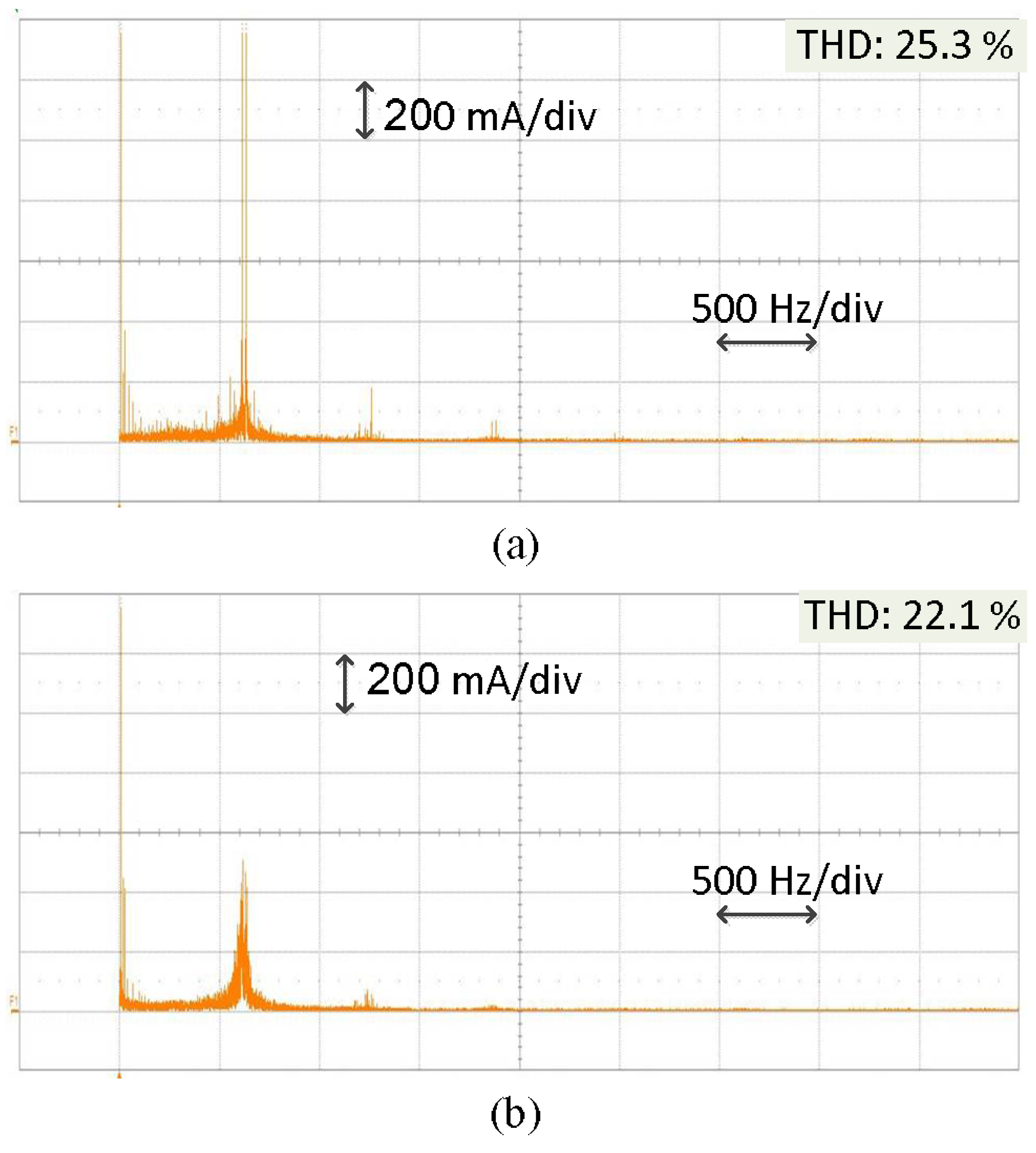
Figure 10.
Experimental frequency spectra of A-phase motor current at 600 rpm under load torque for (a) CPTC and (b) EEMF-PTC.
Figure 10.
Experimental frequency spectra of A-phase motor current at 600 rpm under load torque for (a) CPTC and (b) EEMF-PTC.

Figure 11.
Experimental transient-state response under no-load torque for (a) CPTC and (b) EEMF-PTC.
Figure 11.
Experimental transient-state response under no-load torque for (a) CPTC and (b) EEMF-PTC.


Table 1.
IPMSM Parameters.
| Parameter | Value |
|---|---|
| Torque rating, Te.rat | 60 Nm |
| Power rating, P.rat | 11 kW |
| Current rating, I.rat | 19.9 A |
| Speed rating, | 1750 rpm |
| Permanent magnet flux, | 0.554 Wb |
| Number of pole pairs, Pn | 3 |
| Stator resistance, Rs | 0.349 Ω |
| Stator resistance, Ls | 15.6 mH |
Table 2.
Quantitative comparison for torque ripple and current THD between CPTC and EEMF-PTC.
| Operating Condition | Method | Torque Ripple (Nm) | THD (%) | |
|---|---|---|---|---|
| Speed | Torque | |||
| 200 RPM | 0 Nm | CPTC | 2.107 | 33.5 |
| EEMF-PTC | 1.789 | 32.7 | ||
| 200 RPM | 20 Nm | CPTC | 3.88 | 25.3 |
| EEMF-PTC | 2.46 | 22.1 | ||
| 600 RPM | 0 Nm | CPTC | 1.809 | 29.8 |
| EEMF-PTC | 1.799 | 29.3 | ||
| 600 RPM | 20 Nm | CPTC | 3.01 | 28.4 |
| EEMF-PTC | 2.31 | 23.6 | ||
Disclaimer/Publisher’s Note: The statements, opinions and data contained in all publications are solely those of the individual author(s) and contributor(s) and not of MDPI and/or the editor(s). MDPI and/or the editor(s) disclaim responsibility for any injury to people or property resulting from any ideas, methods, instructions or products referred to in the content. |
© 2022 by the authors. Licensee MDPI, Basel, Switzerland. This article is an open access article distributed under the terms and conditions of the Creative Commons Attribution (CC BY) license (https://creativecommons.org/licenses/by/4.0/).
Share and Cite
MDPI and ACS Style
Alsofyani, I.M.; Mohammed, S.A.Q. Experimental Evaluation of Predictive Torque Control of IPMSM under Speed Sensor and Sensorless Extended EMF Method. Electronics 2023, 12, 68. https://doi.org/10.3390/electronics12010068
AMA Style
Alsofyani IM, Mohammed SAQ. Experimental Evaluation of Predictive Torque Control of IPMSM under Speed Sensor and Sensorless Extended EMF Method. Electronics. 2023; 12(1):68. https://doi.org/10.3390/electronics12010068
Chicago/Turabian StyleAlsofyani, Ibrahim Mohd, and Sadeq Ali Qasem Mohammed. 2023. "Experimental Evaluation of Predictive Torque Control of IPMSM under Speed Sensor and Sensorless Extended EMF Method" Electronics 12, no. 1: 68. https://doi.org/10.3390/electronics12010068
Note that from the first issue of 2016, this journal uses article numbers instead of page numbers. See further details here.