Article

All-SiC Traction Converter for Light Rail Transportation Systems: Design Methodology and Development of 165 kVA Prototype

by
Doğan Yıldırım
1,2,
Mehmet Hakan Akşit
2,3,
Işık Çadırcı
3 and
Muammer Ermiş
1,*
1
Department of Electrical and Electronics Engineering, Middle East Technical University, Ankara 06800, Turkey
2
Transportation, Security, Energy, Automation & Healthcare Systems Business Sector, ASELSAN Inc., Istiklal Marsi Caddesi No. 16, Yenimahalle, Ankara 06200, Turkey
3
Department of Electrical and Electronics Engineering, Hacettepe University, Beytepe, Ankara 06800, Turkey
*
Author to whom correspondence should be addressed.
Electronics 2022, 11(9), 1438; https://doi.org/10.3390/electronics11091438
Submission received: 30 March 2022 / Revised: 24 April 2022 / Accepted: 26 April 2022 / Published: 29 April 2022
(This article belongs to the Special Issue Advanced Technologies in Power Electronics and Motor Drives)

Abstract

:
The design and development of a high-performance 165 kVA, 750 V DC all-silicon carbide (SiC) traction converter for new generation light rail transportation systems (LRTSs) are described. In the design of the traction motor drive, the efficiency of the overall system is maximized and the line current harmonic content of the traction motor is minimized. A complete mathematical model of the physical system is derived to carry out real-time simulations and proper control of the LRTS on a real rail track. The electrical and thermal performances of traction-type SiC power MOSFET modules are compared with those of alternative hybrid and Si-IGBT modules for various switching frequencies. The implementation of the developed system is also described. The performance of the resulting system is verified experimentally on a full-scale physical simulator as well as for various track conditions. Very promising results for the next generation railway traction motor drives have been obtained in terms of performance criteria, such as very high efficiency, low harmonic distortion of the motor line current, low cooling requirement, relatively high switching frequency, and hence, superior controller performance. The effects of the SiC power MOSFET operation on the insulation of the available traction motors are also examined experimentally. This paper is accompanied by a video demonstrating the experimental work.

1. Introduction

Nowadays, high-performance railway traction converters with improved efficiency, reliability, and power quality on the motor side are aimed at in design and implementation works with the developments in power semiconductor technologies.
A comprehensive topological overview of modern electric propulsion architectures and configurations for railway traction, which are used in practice, has been carried out, and the associated power semiconductor technologies from a gate turn-off thyristor (GTO) and insulated gate bipolar transistor (IGBT) to silicon carbide (SiC) power MOSFETs were summarized in [1]. The benefits of using SiC power semiconductors in power electronics applications and how SiC can be a strong and viable candidate for power electronics and system applications have been assessed in [2,3,4,5,6]. The potential applications and advances enabled by wide-bandgap devices in industrial AC motor drives have also been reviewed, and the associated benefits have been highlighted in [7,8,9].
The market for automotive-grade SiC components is showing impressive growth aligned with the rise in electric vehicles (EVs), with SiC power MOSFETs being used in traction inverters [10].
The design and implementation of various all-SiC voltage-source inverters for EV applications have been reported in the literature [11,12,13,14]. A SiC-based high power density (34 kW/L) EV traction inverter was developed for 105 °C ambient temperature operations and 100 kW of peak power output [11]. The design and experimental results for a 30 kW-rated SiC inverter for EV applications, achieving 15 kW/L of volumetric density and a 99.5% peak efficiency were presented in [12]. An optimized SiC power semiconductor-based 2 × 250 kW dual inverter with a power density of 60 kW/L was designed and built for traction applications, as reported in [13]. The optimization of the busbar to achieve the minimal stray inductance has been presented in [15,16]. Similarly, the estimation, minimization, and validation of the commutation loop inductance for a 135-kW SiC EV traction inverter were carried out in [17]. How a traction inverter realized with SiC power MOSFET modules can reduce inverter power losses as compared to a conventional inverter with silicon (Si)-based IGBT and diode power modules has been demonstrated in [3,4,5,18]. Furthermore, in [19], a planarized, high power density 100 kW SiC traction inverter with 1kV DC-link and 1.7 kV all-SiC power MOSFET modules was developed and tested for EVs. A 120 kW-rated SiC inverter for electric buses was also constructed, and its performance was compared to an advanced Si-IGBT inverter [20]. The characterization of a 1200-V, 800-A all-SiC dual module designed for large-scale electric military vehicle applications was reported in [21].
For use in railway traction converters, an outlook of SiC devices and their prospects for developments in traction voltage-source inverters and active front-end converters were considered in [22]. High-voltage hybrid IGBT power modules for the miniaturization of rolling stock traction inverters were reported in [23], while energy savings using all-SiC power modules in traction applications have been reported in [24,25]. In fact, the development of a traction system for Shinkansen high-speed trains by adopting SiC power devices was introduced in 2018 [26] to pursue the weight reduction and compactness of the system. On the other hand, a state-of-the-art 3.3-kV/450-A hybrid power module for traction inverters of rolling stock was reported in [27], combining the Si-IGBT and silicon carbide Schottky barrier diode (SBD) chips. Furthermore, a real-time hardware-in-the-loop emulation of a high-speed rail power system with SiC-based energy conversion was proposed and tested in [28], while a full-scale physical simulator for light rail transportation systems was also built with SiC power MOSFETs in [25]. A PWM control strategy suitable for a SiC traction inverter was proposed and verified by detailed experimental tests in terms of motor current quality, motor loss reduction, motor temperature rise, and running noise suppression in [29], as compared to the conventional PWM control.
An integrated air-cooled, three-phase SiC power block for industry applications was demonstrated in [16]. The characterization and scalable modeling of power semiconductors for the optimum traction inverter design with Si and SiC devices were reported in [30]. A comprehensive comparison of two-level, three-level, and hybrid three-level SiC inverters in high-power, high-speed industrial drive systems was presented in [31].
In this research work, the design methodology and development of a 165 kVA, 750 V DC, 480 V l-to-l, three-phase SiC power MOSFET-based traction motor drive is presented for future use in light rail public transportation systems (LRTSs). As far as the authors know, the application of SiC traction converters to LRTSs has not been published elsewhere and is not commercially available in the market yet, except for in high-speed trains [26]. In the design of the SiC power MOSFET-based traction converter, the quantitative objectives chosen were: (i) higher drive efficiency, (ii) higher reliability, (iii) less harmonic distortion in the applied motor currents, and (iv) wider current, and hence, wider torque bandwidth, while the qualitative objectives were: (v) a simple converter topology, (vi) lower complexity in the control and modulation methods, (vii) high switching frequency to minimize audible noise, and (viii) smaller size as compared to Si-IGBT-based commercially available traction drive alternatives for LRTSs. It must be noted that high-current, and hence, high torque bandwidths arising from a high switching frequency of the SiC power MOSFETs uniquely permit the application of space vector PWM (SVPWM) and field-oriented control over the entire operating ranges of stator frequency, output power, and catenary voltages, whereas, with Si-IGBT-based traction converters, SVPWM should be replaced by optimal PWM, selective harmonic elimination, or selective harmonic mitigation methods at high operating speeds and high powers. Furthermore, field-oriented control should be replaced by scalar control at high operating speeds owing to a reduced switching frequency to fundamental output frequency ratio. The developed system is optimized not only from the inverter viewpoint but also in terms of drive performance. The utilization of 1700 V, 300 A SiC power MOSFET modules was justified by comparing their performances in the LRTS application with those of advanced hybrid and Si-IGBT modules. As compared to commercially available Si-IGBT-based traction motor drives, higher efficiency and much lower total demand distortion have been obtained. Critical aspects of the developed system, such as the power stage layout, the effects of the motor cable length, and the switching characteristics of the chosen SiC power MOSFET modules on the PWM voltage waveforms applied to the motor terminals, etc., have also been investigated. The performance of the resulting all-SiC traction converter in the inversion and rectification modes has been obtained experimentally on a full-scale physical simulator and found to be quite satisfactory. Furthermore, the performance of the custom-designed control system and SVPWM adapted to this application has been tested in real rail track conditions and found to be superior.

2. System Description

2.1. General

A circuit diagram of a three-phase voltage-source traction converter in a light rail public transportation system (LRTS) is shown in Figure 1. A light rail public transportation vehicle usually contains multiple identical traction converters. The first three legs of the converter in Figure 1 operate as a two-level voltage-source PWM inverter in the motoring mode of operation of the three-phase squirrel-cage traction motor, and as a two-level voltage-source PWM rectifier in the regenerative braking mode. The fourth leg of the converter in Figure 1 was designed as a DC chopper circuit to supply controlled power to the braking resistor during regenerative braking or the normal motoring mode of operation whenever the DC catenary line voltage tends to exceed an overvoltage level specified in the EN 50163-2004 standard [32]. Modern DC traction systems for tramways and local railways should conform to the system nominal voltages of 750 V, 1500 V, or 3000 V, as defined in [32]. At the present time, most LRTSs are operated by 750 V DC catenary lines. Therefore, this was chosen as the nominal voltage in this research work (Appendix A).

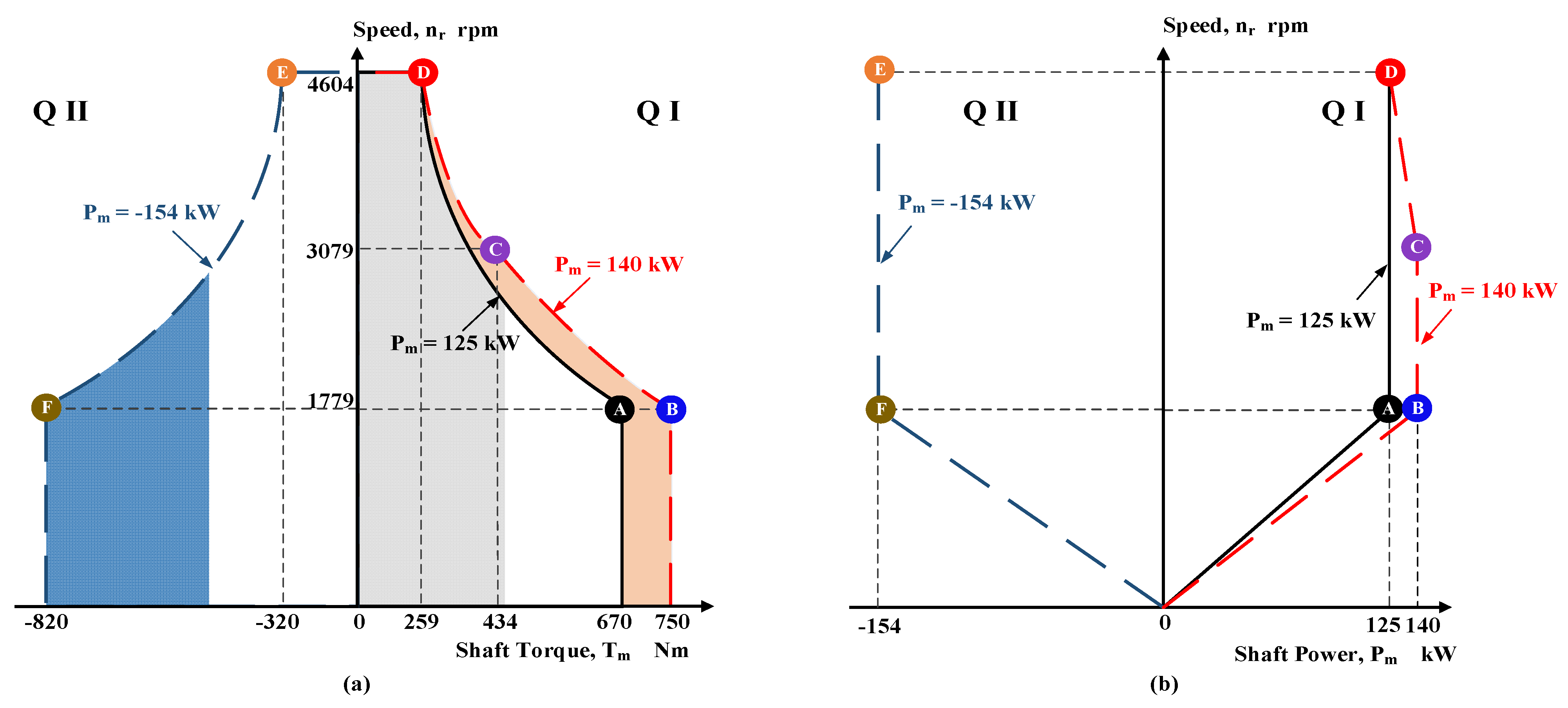
2.2. Operating Characteristics of the Traction Motor Drive

A typical set of speed/torque curves of a traction motor drive is shown in Figure 2a. In the upper half plane (Q I and Q II), the public transportation vehicle is running in the forward direction, and therefore, the speed is positive. The vehicle can only begin to move in the reverse direction usually by reversing the phase sequence of the applied motor voltages after a halt, which corresponds to an operation in the lower half plane. The operating characteristics corresponding to reverse motion are very similar to those of forward operation; therefore, they are not shown in Figure 2a.
In the Q I of the upper half plane, the vehicle operates in the motoring mode, whereas in Q II, in the regenerative braking mode. In Q I, there are two different speed/torque characteristics. The one drawn as a solid line corresponds to the operation of the vehicle in the long term (steady-state operation). However, the one drawn as a dashed line represents the dynamic operation of the drive during the acceleration in the short term. In general, the power rating of the traction converter as marked by the operating point B on the short-term traction motor characteristic is higher than that of the traction motor, marked by the operating point A on the long-term operating characteristic.
It is worth noting that in a railway traction drive, the acceleration and deceleration times are comparable to the thermal time constant of the traction converter. Moreover, the thermal time constant of the traction motor is much higher than that of the traction converter. Therefore, the power rating of the traction converter should not be exceeded in the dynamic operation mode (during acceleration and deceleration). In Q I, the long-term operating characteristic is composed of two parts: the constant torque part and constant power region. On the other hand, the short-term operating characteristic is composed of three parts: the torque limit, power limit, and high-speed field-weakening regions.
Short-term operation in the regenerative braking mode takes place in Q II. Therefore, the unique speed/torque characteristic is composed of a constant torque part and a constant power region. Since deceleration during regenerative braking takes place more rapidly than acceleration during the motoring mode of operation, absolute values of the deceleration coefficient limit and torque limit are usually higher than the acceleration limit and corresponding torque limit. Variations in speed against the shaft power were determined and then plotted as shown in Figure 2b.

2.3. Mathematical Modelling

A complete mathematical model of a public transportation vehicle running on a specific rail track is given in this subsection. The detailed derivations of mathematical models for the physical system that carries out the real-time simulation of not only the light rail public transportation vehicles but also of heavier vehicles, are already given in [25].
The force–balance equation on the translational motion side is shown in (1).
m F s h a f t = M e q v d v d t + F r + F c u r v e + M g s i n α x
where m is the number of traction motors, F s h a f t is the tractive force per motor reflected to the translational motion side by assuming rigid shafts, M e q v is the mass of the static and rotating parts of the transportation vehicle, excluding motor inertias, v is the linear speed of the vehicle, F r is the sum of the static and dynamic resistances and drag force acting on the vehicle, F c u r v e is the curve resistance force, M is the static mass of the vehicle, g is the gravitational acceleration, and α is the slope angle of the rail track as a function of displacement, x , from a reference point. M e q v in (1) has three components, as shown in (2).
M e q v = M + J g b 1 r 2 + J w 1 r 2
where J g b and J w are the moments of inertia of all gear-boxes and wheels on the low rotational speed side, respectively. Equation (1) can refer to the motor shaft by substituting v = ω r / n and dividing both sides by the gear down ratio, n , and m. These yield (3), as follows:
J m + M e q v r 2 m n 2 d ω d t = T m 1 m T r + T c u r v e + M g r n s i n α x
where J m is the motor inertia in kg-m2, ω is the motor speed in mech-rad/s, T m is the torque output of each traction motor in Nm, r is the radius of the wheels in m, and T r and T c u r v e are the load torque components owing to the train resistance and the curve resistance of the rail track, respectively.
T r and T c u r v e are expressed as shown in (4) and (5).
T r = A + B v   M + C v 2     r / n
T c u r v e = D M g / R x   r / n
In (4) and (5), A is the friction force coefficient per unit weight of the vehicle, which is independent of the speed, B is a constant per-unit weight of the vehicle to give a dynamic friction force proportional to the speed, C is the air resistance coefficient that, when multiplied by the square of the speed, gives the aerodynamic drag force acting on the vehicle, D is the curve resistance coefficient, and R is the radius of any curve on the rail track.
The technical specifications of the associated vehicle system that is investigated in this paper are given in Table 1. The corresponding traction motor data, and quantified two-quadrant operating characteristics per traction motor are given in Table 2 and Table 3, respectively.

3. Converter Design

3.1. Design Objectives

Simple converter topology, lower complexity in the control algorithm and modulation methods for the whole operating range, high switching frequency to minimize audible noise, and a smaller size are the qualitative objectives in the converter design. On the other hand, high efficiency, high reliability, less harmonic distortion in the applied motor currents, especially in the low-order harmonic range, and a wide current, and hence, high torque bandwidth, are the quantitative design objectives. In the design phase, the traction converter, which optimizes not only the initial cost/kW-converter but also the operating cost (lower energy consumption, less maintenance), should be preferred.
Two-level classical three-phase bridge topology without parallel or series-connected power semiconductors in all legs in conjunction with the most common space vector PWM as the modulation technique and field-oriented control to adjust the rotor flux during operation meet some of the design objectives given above. To complete the optimum design work, the most suitable types of power semiconductors among Si-IGBT, hybrid IGBT, asymmetrical IGCT, and SiC power MOSFET modules and the optimum switching frequency for the chosen power semiconductor should be determined by carrying out some computer simulations. In traction converters supplied with 750 V DC catenary lines, asymmetrical IGCTs were not chosen as the main switching elements because of their very high current and voltage ratings, which are suitable only for 1500 and 3000 V DC catenary lines.
For 750 V DC catenaries, all traction systems should withstand 500–900 V continuously, 1000 V for 5 min, and 1000–1270 V on a straight line for durations of 1 s to 20 ms, as recommended in Annex A of [32] and as shown in Appendix A. This makes it necessary for the use of power semiconductors to have a standard blocking voltage capability of 1700 V. In addition to this, the current rating of candidate power semiconductors should also be determined initially without specifying some thermal limitations. In this application, the maximum apparent power that will be delivered by the inverter is 185 kVA, as given in Table 3. The associated maximum current per inverter, Imax in Appendix B, which will be supplied from the catenary line through the LDC when the catenary line voltage is 750 V DC, is calculated to be 200 A DC. The current through each switch (the controlled semiconductor and its antiparallel diode) is a chopped alternating current waveform and is a combination of the current component drawn from the catenary and the DC link capacitors. In this application, the maximum value of the peak current through the controlled semiconductor is 320 A while delivering 185 kVA to the traction motor at point B in Figure 2. Therefore, the continuous DC current rating of the chosen power semiconductor should be at least 300 A by considering a small safety limit.
In this research work, Wolfspeed CAS300M17BM2 SiC power MOSFET modules were employed in the design and implementation of the traction converter. In order to illustrate the benefits of SiC power MOSFETs in traction motor drive applications over new-generation IGBT-based systems, the performances of three traction converters employing Infineon FF300R17KE4P Si-IGBT, Mitsubishi CM300DY-34T Si-IGBT, and Fuji 2MSI400VAE-170-53 Hybrid IGBT were determined by considering only the thermal limitations. Although these IGBT modules were developed for standard industrial applications instead of traction applications, they were chosen in this comparison work because of their compatible voltage and current ratings with Wolfspeed CAS300M17BM2. The simulation software of IPOSIM, Melcosim, Fuji IGBT Simulator, and Speedfit were used in the performance calculations of FF300R17KE4P, CM300DY-34T, 2MSI400VAE-170-53, and CAS300M17BM2, respectively, for different switching frequencies.
In AC motor drives, employing sinusoidal PWM (SPWM), discontinuous PWM (DPWM), or SVPWM if the modulation index, Mi, is less than or equal to unity, the ratio of the carrier frequency to the fundamental output frequency is recommended to be greater than 21 in the literature [33,34] for an acceptable THD in motor currents. In this application, the operating stator frequency changes from 0 to 155 Hz, as given in Table 3. Throughout the speed control range, the carrier frequency can either be varied proportionally with the stator frequency or can be kept constant at the value corresponding to the maximum stator frequency. The associated carrier frequency, fC, values are shown in Table 4, specifically for Si-IGBT-based converters.
In these simulations, the thermal resistances given in Appendix C (Table A1) were used, and forced-air cooling by employing two sets of large standard heatsinks (one for comparison purposes, the other one for optimum use) was assumed.
The thermal analysis based on the computer simulations was justified also by hand calculations. Table 5 summarizes the results of the associated simulation works in detail. In these simulations, the maximum kVA in the steady-state was considered to be 165 kVA. The following conclusions can be drawn from these results:
  • The optimum heatsink size for the SiC power MOSFET-based converter is Rth,ha = 0.018 K/W with forced-air cooling for a switching frequency range from 5 to 10 kHz.
  • When the same heatsink size is used for Si-IGBTs, Tvj exceeds the pre-specified maximum operating temperature of 120 °C at a switching frequency of 5 kHz. In order to make fC = 5 kHz, a larger size heatsink of Rth,ha = 0.013 K/W should be used only for some of the advanced Si-IGBTs.
  • The hybrid IGBT can be operated at fC = 5 kHz even for Rth,ha = 0.018 K/W. Furthermore, the larger heatsink of Rth,ha = 0.013 K/W allows for its operation at fC = 10 kHz.
Table 5. Thermal performance of SiC power MOSFET modules in a traction converter as a function of carrier frequency and stator frequency in comparison with those of hybrid and Si-IGBT modules.
Switching Frequency, fC (Hz)Stator Frequency, fs (Hz) S = 165 Kva, pf = 0.81 lag, Iout = 200 Arms, Vl-l = 480 Vrms, Mi = 0.905, TA = 40 °C, Rth,h-a = 0.018 K/W
‡ Loss and Tvj Values Calculated for Rth, ha = 0.013 K/W
Si-IGBT Module
(FF300R17KE4)
Infineon
Si-IGBT Module
(CM300DY-34T)
Mitsubishi
Hybrid IGBT Module (2MSI400VAE-170-53)
Fuji Electric
SiC MOSFET Module (CAS300M17BM2) Wolfspeed/Cree
IGBTDiodeIGBTDiodeIGBTDiodeMOSFETDiode
Sw.Cond.Sw.Cond.Sw.Cond.Sw.Cond.Sw.Cond.Sw.Cond.Sw.Cond.Sw.Cond.
126060Loss (W)51163173350170125048142630----
Tvj (°C)94.375.584.776.577.973.1--
325560Loss (W)143168473313517737491271451431-- -
Tvj (°C)117.192.4108.295.891.283.8-
3255155Loss (W)1421694631.713517736491261451431----
Tvj (°C)115.291.1108.295.890.283.4--
500060Loss (W)240
(205)
174
(143)
82
(74)
34
(28)
218
(218)
150
(150)
48
(48)
41
(41)
199148223120263-14
Tvj (°C)141.9
(127.6)  
110.7
(101.2) 
131.2
(117.5) 
115.8
(102.1) 
103.493.5109.290.2
5000155Loss (W)237
(204)
174
(144)
79
(69)
32
(27)
218
(218)
150
(150)
48
(48)
41
(41)
199148223119262-14
Tvj (°C)138.2
(124.9)  
107.7
(99.1)  
131.2
(117.5) 
115.8
(102.1) 
102.193.110889
10,00060Loss (W)5911902603541617711349450
(363)
157
(128)
42
(41)
32
(27)
44271-14
Tvj (°C)>200191.6186163.4145
(116.3) 
126.2
(101.6) 
115.795
10,000155Loss (W)5911912583441617711349446
(362)
156
(127)
42
(41)
32
(26)
42270-13
Tvj (°C)>200185.2186163.4142.4
(114.6) 
125.2
(101.1) 
114.893.8

3.2. Preliminary Considerations for Optimum Carrier Frequency

Si-IGBT and hybrid IGBT modules have a maximum allowable virtual junction temperature of 150 °C, while for the SiC power MOSFET, it is 175 °C. In LRTS applications, the operating point of the vehicle and its traction converters rapidly change over a wide operating area. Therefore, the peak value of the virtual junction temperature should not exceed 120 °C during intermittent operation for a longer semiconductor life cycle and higher reliability. As can be understood from Table 5, FF300R17KE4P, CM300DY-34T, and 2MSI400VAE-170-53 can be operated safely up to switching frequencies of 3255 Hz, 3255 Hz, and 5000 Hz, respectively. The SiC power MOSFET, however, can be operated at much higher switching frequencies in this application, i.e., over 10 kHz, as is proven later in Section 5.1. The Si-IGBT and hybrid IGBT modules considered in Table 5 do not have packages suitable for LRTS applications because of their Ni-coated Cu baseplates. The use of Cu as a base plate material is common in standard industry applications for its well-known advantages with regard to easy mechanical handling and high thermal conductivity. However, its major disadvantage in traction applications where the power semiconductors are subjected to a high number of thermal and power cycles is the mismatch of the coefficient of thermal expansion to the ceramic substrates [35], which usually destroys some of the power semiconductors in the long term.
On the other hand, an AlSiC baseplate is expected to be integrated into the traction-type SiC power MOSFET modules in the near future. This new technology will provide high-reliability solutions for the thermal management of power semiconductors employed in traction applications, with nearly half the thermal expansion coefficient compared to Cu, in contrast to a thermal resistance that is twice as high [36]. If the IGBT modules in Table 5 were furnished with AlSiC baseplates, the virtual junction temperatures would be higher and the maximum switching frequency could be considerably lower because of their nearly twice-as-big junction-to-heatsink thermal resistance values.
Infineon FF650R17IE4D_B2, F600R17KE3_B2, Mitsubishi CM800DZB-34N, and Fuji Electric 2MBI600VG-170E-50 are the smallest 1700 V modules developed specifically for traction applications. Their current ratings are 650 A, 600 A, 800 A, and 600 A, respectively, and they are furnished with AlSiC baseplates. In this application, they can be switched at higher frequencies at the expense of a bigger traction converter size and higher initial cost. It is also worth noting that the virtual junction temperatures in Table 5 are the peak values. The peak-to-peak ripple of the virtual junction temperature in a traction converter depends on the output frequency of the converter. As the output frequency is increased while keeping the power output nearly the same, the peak value of the virtual junction temperature in Table 5 slightly decreases, as expected.
A further advantage of SiC power MOSFETs over hybrid and Si-IGBTs is their ability to conduct a reverse current, thus reducing the conduction loss at relatively high operating powers. An electrical connection diagram of the first leg of the traction converter and the associated all-SiC half-bridge module are shown in Figure 3a,b, respectively. Low device currents in the reverse direction are carried only by the SiC power MOSFET chip. However, high device currents in the reverse direction are shared between the SiC power MOSFET chip and the SiC Schottky diode chip. The transition point for the device current mentioned above can be expressed as in (6).
i D S x R d s o n V F t h
where i D S is the instantaneous value of the drain-to-source current, R d s o n the equivalent resistance of the SiC power MOSFET chip during conduction, and V F t h is the threshold forward voltage drop of the SiC Schottky diode.
The current sharing between the MOSFET and Schottky diode chips when both of them are conducting can be formulated as shown in (7). The forward conduction voltage drop, V F , of the SiC Schottky diode depends on the forward current, i D , and its virtual junction temperature, T v j , while the V F t h depends only on the T v j .
i D S 1 = V F + i S 1 r d i o d e R d s o n + r d i o d e i D 1 = V F i S 1 R d s o n R d s o n + r d i o d e
In Figure 4, the current waveforms through S1, D1, S4, and D4 on the SiC power MOSFET-based inverter are compared with those of the Si-IGBT-based inverter. In Figure 4a,b, the Si-IGBT-based inverter is delivering 173 kVA at 0.81 pf to the motor stator. Corresponding current waveforms for the same operating point in the SiC power MOSFET-based inverter are as shown in Figure 4c,d. On the negative half-cycle of the line current iA (t), the negative current is shared between the SiC MOSFET chip and its anti-parallel SiC Schottky diode. Since the forward voltage drop of the body diode of the SiC power MOSFET is much higher than that of the SiC anti-parallel Schottky diode, the body diode carries a negligibly small current. The SiC anti-parallel Schottky diode is formed separately and placed into the same package, as can be understood from Figure 3. On the other hand, when the current delivered by the SiC power MOSFET inverter is relatively low, almost all of the reverse currents will flow through the SiC MOSFET chip, as can be understood from Figure 4e,f.
In this application, the transition between these two modes occurs when the output power of the inverter tends to exceed 75 kVA. If there was no reverse conduction ability of the SiC MOSFET chip, all of the reverse currents would flow through the anti-parallel Schottky diode, as in the case of a Si-IGBT. This would increase the total conduction loss of the traction inverter by nearly 80 W when it is supplied with Vdc = 750 V and delivers 480 V l-to-l, 173 kVA at 0.81 pf to the stator.

3.3. Application of Space Vector PWM

In most variable-frequency AC motor drive applications, SVPWM is preferred as the carrier-based continuous modulation technique by designers. This is because of (i) a higher DC bus voltage utilization, (ii) relatively low TDD for the line current waveforms, (iii) the simplicity and easiness in the implementation, and (iv) the utilization of fixed switching frequency as the common approach. The application of SVPWM to the traction converter of LRTS described in this paper is summarized in Figure 5.
As a common approach for general-purpose PWM converters in the literature [34], the minimum carrier frequency should be chosen as 21 f s m a x = 21 × 155 = 3255   Hz in order to obtain a reasonably low TDD for the line currents. Nowadays, the common switching frequency of Si-IGBT-based traction converters of LRTS systems is around 2 kHz. This yields 33 pulses in one complete cycle of a rated stator frequency of 60 Hz, while only 13 pulses when the fs is at its maximum value of 155 Hz. This pulse number in one complete cycle of the applied stator voltage waveform is very low, and hence, causes high line current harmonics and torque ripple, thus adversely affecting the stability of the motor drive. To avoid these drawbacks of a low switching frequency, a more complicated control philosophy and control system are needed in addition to replacing the SVPWM with preprogrammed modulation methods such as the OPWM, SHEPWM, SHMPWM, etc., at high stator frequencies, and hence, shaft speeds. Alternatively, much higher switching frequencies can inherently eliminate this problem, e.g., there will be 64 pulses in one complete cycle of f s = 155   Hz if the fC is set to 10 kHz. This can be achieved by the use of SiC power MOSFETs instead of Si-IGBTs. This is why SVPWM could be successfully applied over the entire operating range of a SiC traction motor drive in this research work. With the advance in SiC power MOSFET technology, these kinds of traction motor converters are expected to be supplied not only from 750 V DC but also from 1500 and 3000 V DC catenary lines. In the application of SVPWM as the modulation technique, operating regions are shown by colored circular areas in Figure 6 in terms of the DC catenary voltage of the minimum value in Figure 6a, the rated value in Figure 6b, and the maximum continuous value in Figure 6c.
Furthermore, the frequency and output voltage of the inverter, and apparent and active power consumed from the inverter by the traction motor all change during the operation of the LRTS.
It is not possible to create a rated applied motor voltage of 480 V l-to-l in the linear modulation region (Mi ≤ 1) when the DC catenary voltage is at its minimum value, Vdc = 600 V. The rated motor voltage can only be obtained by operating the converter over the modulation region, which makes field-oriented control algorithm very complicated. Furthermore, operation at Vdc = 600 V reduces the rated power transfer capability of the converter by 20%. This is because, as found in [37] (Figure A2 in Appendix B), the maximum current that can be delivered by the converter is defined for the rated value of the catenary voltage, Vdc = 750 V. The operation of the railway vehicle is also permissible for the catenary voltage levels from 600 to 500 V DC, but with a significant reduction in the amount of the power that can be delivered from the converter. The operating region in Figure 6b corresponds to the rated catenary voltage of 750 V DC, for which the rated motor voltage of 480 V l-to-l can be obtained with a modulation index of Mi = 0.9. The Mi should be reduced to 0.75 in order to give the rated motor voltage when the catenary voltage is at its continuous maximum value of 900 V DC, as illustrated in Figure 6c. Intermittent operation takes place when the Vdc tends to exceed 900 V DC, as seen in Figure A1, Appendix A.

3.4. Controller

The block diagram of the custom-designed digital control system is shown in Figure 7. It is implemented on the TMS320F28377 DSP platform. The major task of the control system is to maintain the operation of the traction motor drive in safe operating areas in the first and second quadrants of the speed–torque plane in Figure 2a, according to the torque reference signal, T r e f , sent by the driver in the manual operation mode or by the communication-based train control (CBTC) system in the automatic operation mode. This is achieved in the control system by simultaneously running the following facilities:
(i) Field-oriented control is implemented to keep the rotor flux constant from zero speed to rated speed, whereas field weakening is applied above the rated speed by controlling the direct axis component of the motor current, I d r e f .
(ii) The I d and I q components of the stator currents are calculated from the actual currents, i A , i B , and i C , by the successive application of phase and commutator transformations. Commutator transformation requires the variations in θ e in time. If the stator currents are all purely sinusoidal and the motor is operating in steady-state, I d and I q would be pure DC currents that correspond to a constant amplitude MMF wave rotating at a constant speed, the so-called the synchronous speed, ω e . The electromechanical torque, T e , is kept under control by varying the quadrature axis component, as expressed in (8). As can be understood from Figure 7, I q r e f is directly related to I d r e f and T e , as in (8).
I q r e f = 2 3   1 p p L r L M 2 T r e f I d r e f
where L r is the rotor self-inductance per phase referred to the stator, L M is the magnetizing inductance, and p p is the number of the pole pairs.
L r can be related to L M , as in (9), in terms of the rotor leakage inductance referring to the stator, L l r .
L r = L M + L l r
(iii) Although the traction converter is a voltage-source converter (VSC), the direct and quadrature axis components, and hence, the actual stator currents, iA, iB, and iC, are controlled by applying the appropriate line-to-neutral, and hence, line-to-line voltages to the stator terminals. The PI controllers in Figure 7 tend to make the actual I d equal to I d r e f , and the actual I q equal to I q r e f * . The I d r e f is a motor-dependent quantity to set the rotor flux. as explained in (i). The I q r e f is calculated from the T r e f and I d r e f in terms of the motor parameters, L r and L M . The core saturation affects the L M , and hence, the I q r e f in (8). The I q r e f is then updated by the action of the active damping system to give I q r e f * .
(iv) Line current waveforms may contain low- and high-frequency harmonic components. High-frequency harmonics changing with the switching frequency and its multiples are successfully filtered out by the analog filters included in the current sense circuits. Slightly non-identical motor parameters, semiconductor characteristics, and non-idealities cause the production of low-order super-harmonics. These harmonic components will then be reflected to the I d and I q . Since the sampling and switching frequencies of the traction converter are high ( f s w = 10   kHz ), the bandwidth of the control system is wide, and hence, the low-order harmonics in I d and I q are satisfactorily filtered out by the PI controllers after comparing them with the purely DC reference signals, I d r e f and I q r e f * . If it was an HV-IGBT-based converter, the f c could be in a lower range, from about 1.5 to 3 kHz. This causes the existence of low-order harmonics in the I d and I q , with higher magnitudes. Therefore, some further reference frames that rotate synchronously at individual harmonic frequencies and the corresponding PI controllers for each low-order significant harmonic component might be necessary for the implementation. The PI controllers in Figure 7 create the necessary gating signals for the SiC power MOSFETs through the use of dq-to-αβ transformation and the SVPWM signal generation. A brief description of the application of SVPWM to the variable speed operation of the traction motor in a wide range is given in Figure 6.
(v) The speed of the rotating magnetic field in the airgap, ω e , is calculated by adding the slip speed, s ω e , to the rotor speed, ω r e , in elec.rad/s. The rotor speed is calculated from the measurements of the shaft encoder with a 160-tooth encoder wheel. The s ω e is computed from the I d r e f   and   I q r e f * in terms of the R r and L r as shown in (10).
s ω e = R r L r I q r e f * I dref
The rotor resistance per phase, referring to the stator, R r , is compensated by the rotor temperature estimation from the PT100 measurement T s . The I q r e f * is related to the I q r e f , as in (11).
I q r e f * = a n I q r e f
The control system calculates the ratio of the unfiltered, v d c t , to the filtered, V d c * t , values, as expressed in (12).
a = v d c t / V d c * t
The filtered DC link voltage signal, V d c * t , is obtained by using a digital notch filter, the transfer characteristic of which is shown in Figure 8. It provides an effective filtering performance in the frequency range of 16 Hz to 68.6 Hz. The active damping circuitry modifies the set value of I q by defining the new set value as in (11). A is a real number around unity, and its optimum power coefficient, n = 11, was found by the simulations and verified experimentally.
(vi) The design of the input filter consisting of the series L d c and shunt C d c and having a corner frequency of 50 Hz is described in the next subsection. Nonlinearities, non-ideal operating conditions, and non-identical system parameters on both the catenary line and the traction inverter sides may produce inter-harmonics at or near the resonance frequency of 32 Hz and be superimposed on the V d c . The AC current through the L d c and the AC voltage on the C d c will then be amplified significantly, resulting in destructive effects on the system components. Therefore, resonance or amplification risks of the input filter should be avoided by adding a significant damping effect to the input filter. The conventional solution is the addition of a sufficiently large series resistance or a small shunt resistance to the circuit of the input filter. Unfortunately, these passive damping techniques are dissipative and, therefore, rarely used in modern systems. In this research work, active damping, which is equivalent to connecting a virtual dissipative element, was implemented to suppress the generated uncharacteristic current harmonics at or around the resonance frequency via the control system, and thereby, the power circuit of the traction converter.

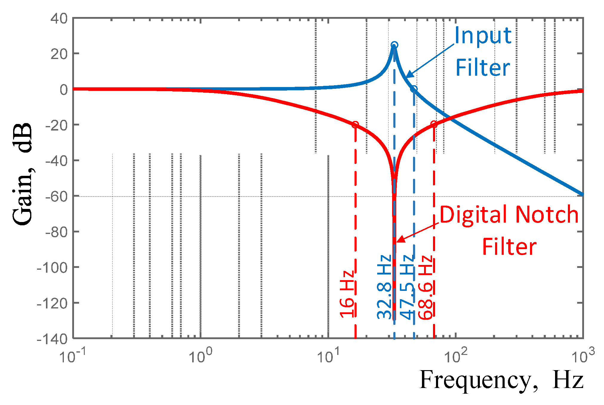
3.5. Input Filter Design
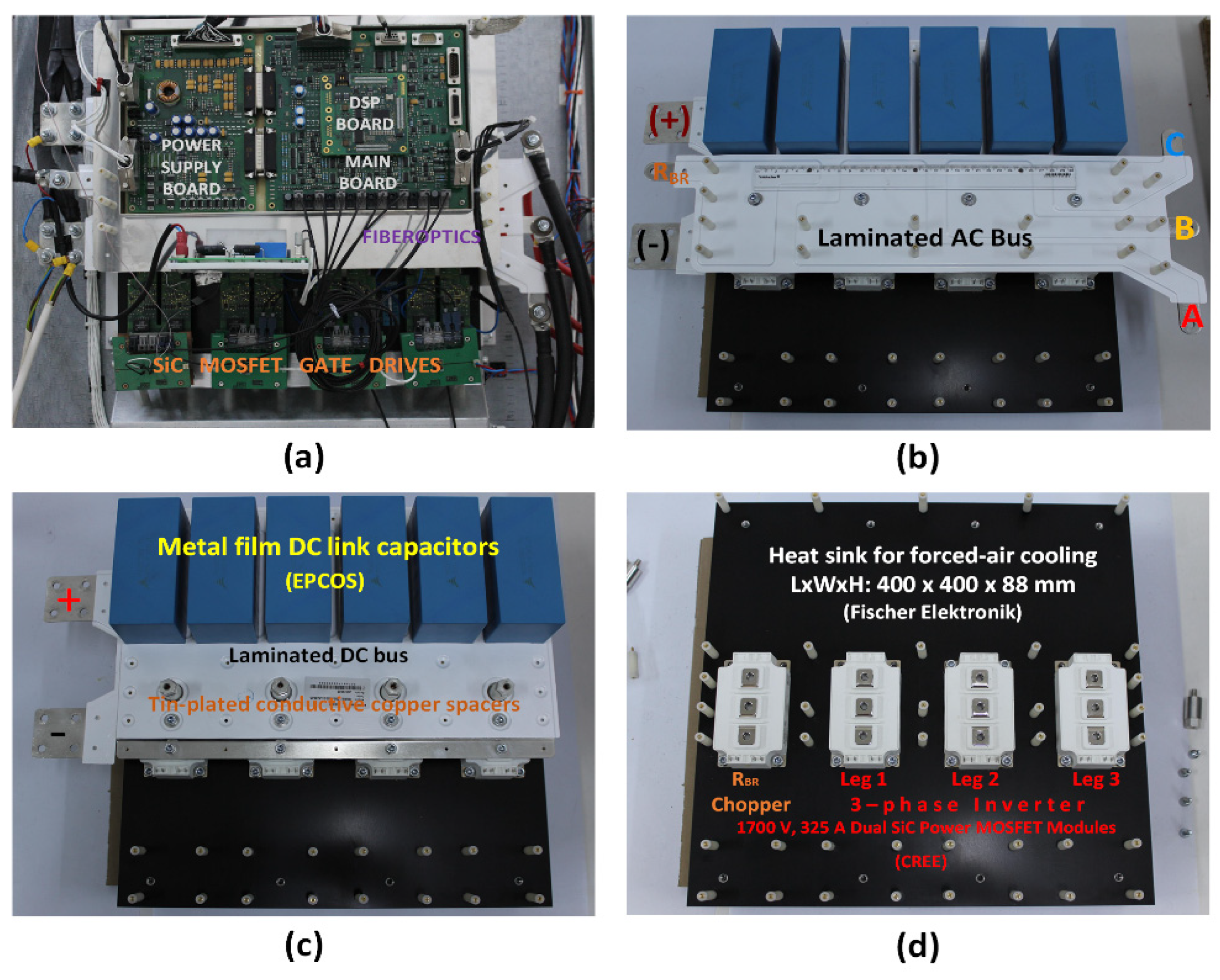
A low-pass second-order L d c C d c filter is to be used on the DC side of the traction converters in LRTSs, as shown in Figure 7. The basic functions of these input filters are (i) to suppress the transient voltage components produced on the DC catenary side; (ii) to enact the C d c as an energy storage element to maintain the input voltage of the traction converter during ~3–4 ms bouncing periods of the pantograph while the LRTS is running on the rails; in such periods, the pantograph is displaced from the catenary line, and hence, the traction converter draws the energy stored in C d c ; (iii) to limit the rate of the rise of currents as a result of short circuits occurring on the traction converter side; this is achieved by using a sufficiently large series inductor, L d c , which provides the safe operation of the DC contactor while clearing the fault; (iv) to filter out 600 Hz voltage ripples and their multiples generated by the rectifiers that supply the DC power to the catenary line or third rail since they are usually 12-pulse uncontrolled rectifiers; and (v) to suppress time-varying low-frequency harmonics (especially 100 Hz and its multiples) that are superimposed on the catenary voltage and, at the same time, injected from the traction converter side [38,39].
In view of the above considerations, the C d c and L d c values are expressed as shown in (13) and (14).
I m a x   Δ t = C d c   Δ V
where Δ t is the bouncing period during which the DC link voltage drops by Δ V owing to the charge I m a x   Δ t extracted from C d c , for the I m a x defined in Appendix B.
The substitution of I m a x = 200   A , Δ t = 4   ms , and Δ V = 750 600 = 150   V gives the minimum C d c = 5.3   mF . C d c = 5.9   mF is then formed by using a 4.7 mF heavy-current capacitor for traction application and paralleling it with six 200 µF metalized polypropylene film capacitors distributed on the laminated DC bus of the traction converter. The resonance frequency f 0 is set to 32 Hz, which is sufficiently lower than the 50 or 60 Hz grid frequency and sufficiently higher than the 10 Hz frequency, as recommended in [38,39,40]. The L d c is, therefore, determined to be 4 mH, from (14).
L d c = 1 / 2 π f 0 2 C d c
The transfer characteristic of the resulting input filter is plotted in Figure 8 against the same frequency range as the digital notch filter used in the active damping circuitry. The unity gain is obtained at f t r = 47.5   Hz for the input filter. Harmonic frequencies lower than f t r (in fact, lower than 68.6 Hz) are successfully suppressed by active filtering action via the digital notch filter. Low-order and high-frequency harmonics, including the switching frequency, its side bands, and multiples, appearing on both the catenary and traction sides are successfully suppressed by the input filter.

4. Implementation

Figure 9 shows the all-SiC power MOSFET-based three-phase, variable-frequency and variable-voltage traction converter developed in this research work. In the implementation of the power stage, top-to-top mounting technology is preferred in order to minimize the wiring and cabling inductances and maximize the volume utilization. The four layers of the power stage are shown in Figure 10.
SiC power MOSFETs have very fast turn-on and turn-off transitions, resulting in the generation of high di/dt and dv/dt at many points of the power circuitry. Since SiC power MOSFETs are switched on and off at much higher frequencies in comparison to those of Si-IGBTs, their utilization would be worsened i.e., an increase in the switching losses during turn-off, as well as in the voltage and current overshoots, and a ringing phenomenon would occur during turn-on and -off in cases where the parasitics were not minimized in the design phase. This is the main reason why special attention was paid to the design of the power stage and laminated busbars, as illustrated in Figure 9 and Figure 10. Furthermore, the gate-drivers are positioned very close to gate–source terminals of the SiC power MOSFETs, as shown in Figure 9a,b and Figure 10a in order to decrease the parasitics. The increased resistance of the gate-driver could be an alternative countermeasure at the expense of slower turn-on and -off.
In order to minimize the stray inductance of the current path between the high-frequency metalized film capacitors (blue colored) and SiC power MOSFETs, the laminated DC bus was designed with a minimum spacing between the (+) and (−) busbars by means of a high dielectric constant insulation material (Kapton). The high-frequency metalized film capacitors are uniformly distributed at the D1-S2 terminals of the SiC power MOSFET modules on the laminated busbar so as to supply the switching frequency currents with minimum inductance in the current paths. The stray capacitance from the SiC power MOSFETs to the heatsink and from the cables to the chassis was minimized to avoid the flow of high common-mode currents.

5. Experimental Results

The performance of the all-SiC power MOSFET-based traction motor drive was tested on the full-scale physical simulator built in the Traction Systems R&D Laboratory for Railway Transportation. This full-scale simulator is on a per motor base and its details are described in [25]. This paper is accompanied by a video demonstrating the experimental work as the Supplementary Material.

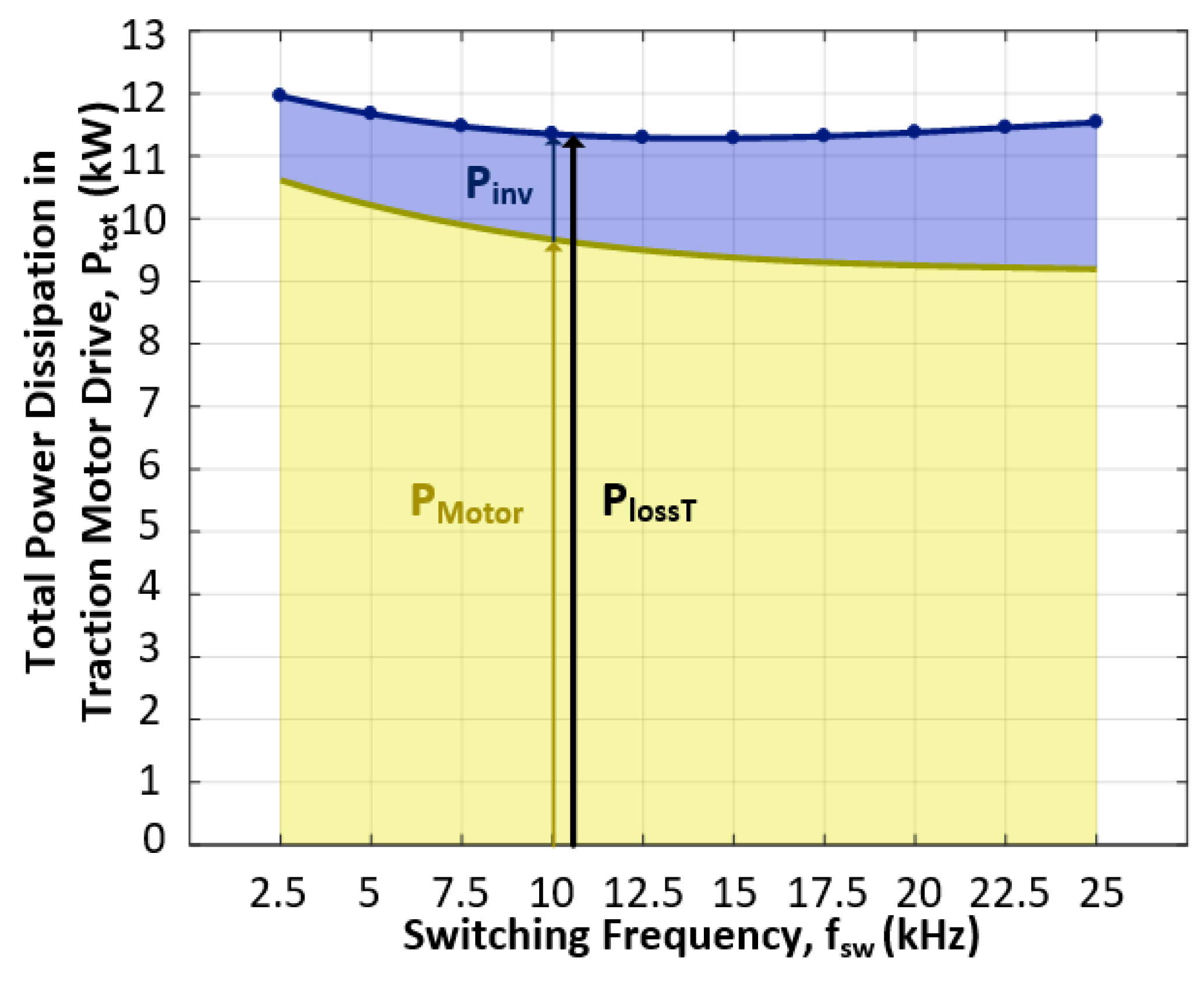
5.1. Determining Optimum Switching Frequency

In this research work, the efficiency of the traction motor drive was maximized by switching the traction inverter at an optimum frequency. The variation range of the virtual junction temperature of the SiC power MOSFETs was affected by the switching frequency during the operation of the traction motor drive. Lower junction temperatures gave rise to significantly longer lifetimes for power semiconductors. The overall efficiency of the traction motor drive was the product of the traction inverter efficiency and the motor efficiency. The major power loss components were conduction and switching losses for the inverter, and copper and core losses for the traction motor. These power loss components were determined by tests as well as by some detailed simulations.
In order to determine the power loss components of the traction motor, it was driven at a synchronous speed (nr = 1800 rpm) by the loading machine (Figure 9c) when the rated voltage (Vs = 480 V l-to-l) and frequency (fs = 60 Hz) were applied to the stator and the stator line current and power input to the stator were measured as a function of the inverter switching frequency. The core loss was separated from the stator copper loss by using the stator resistance provided by the motor manufacturer as a function of the inverter switching frequency and the stator temperature and line currents. Furthermore, the friction and windage loss component was measured in the usual way after decoupling all the rotating parts from the motor shaft. The variations in the core loss and stator copper loss components at the synchronous speed are shown in Figure 11 as a function of the switching frequency.
The switching and conduction loss components of the traction inverter were calculated by Speedfit Design Simulator of Wolfspeed as a function of the switching frequency, as shown in Figure 12.
The total power dissipation of the traction motor drive was then obtained by taking into account the motor losses and inverter losses at the same switching frequency. It is worth noting that the stator and rotor copper loss components were calculated at the rated operating conditions and then added to the core loss, friction, and windage loss components of the motor, and the conduction and switching losses of the inverter at each switching frequency. The variations in the total loss of the motor drive as a function of the switching frequency were then plotted, as shown in Figure 13. A closer examination of this curve shows that the total power dissipation at the rated operating point was minimized in the switching frequency range from 10 to 17.5 kHz. Although fsw = 15 kHz yielded the minimum total power dissipation, and hence, the maximum drive efficiency, it caused a higher average junction temperature during operation as compared to fsw = 10 kHz (Figure 13). Therefore, in this research work, fsw = 10 kHz was chosen in order to obtain a longer lifetime for the SiC power MOSFETs [40].

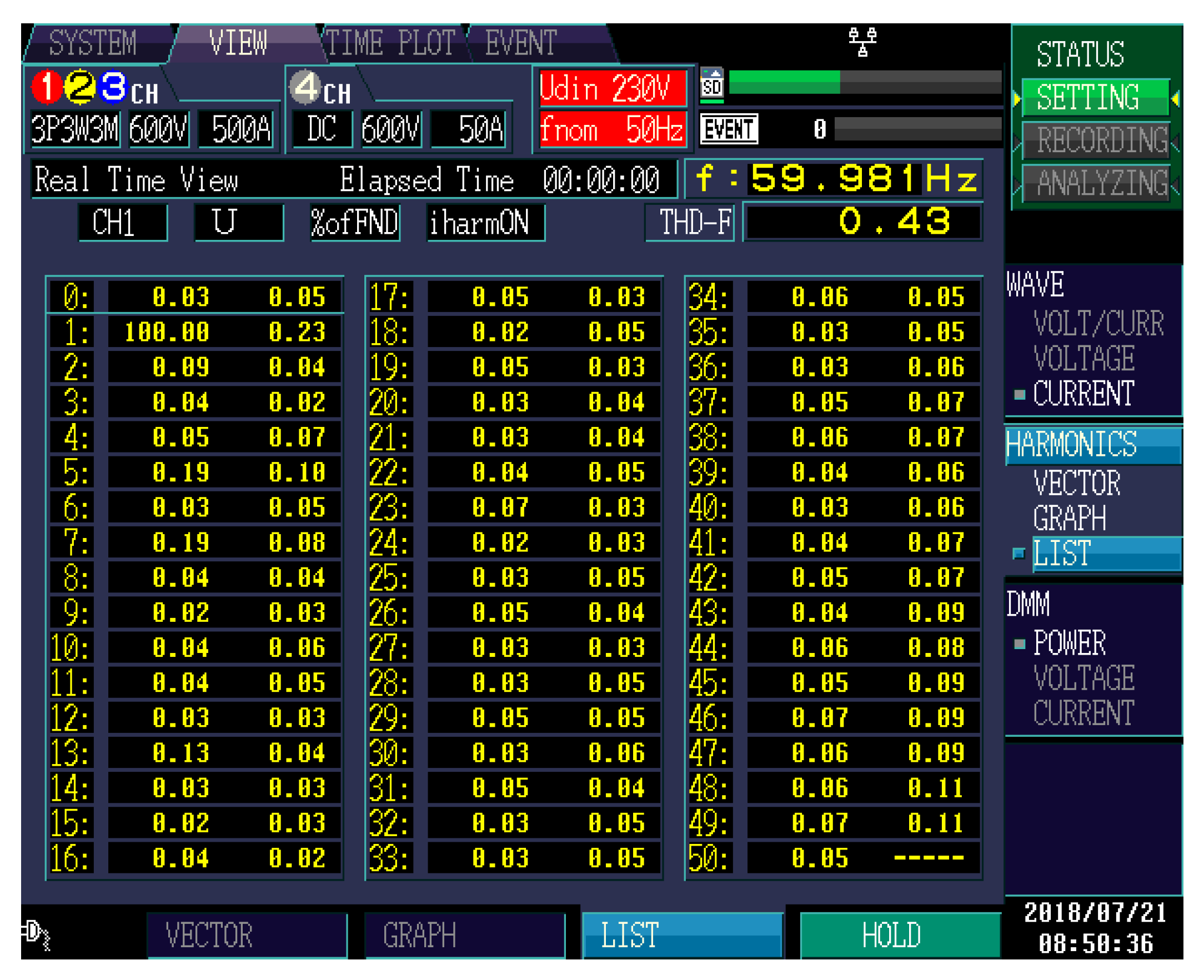
5.2. Steady-State Performance of the Traction Converter

The line-to-line voltage, line current, DC link voltage, and DC link current waveforms of the traction inverter at the rated operating conditions and the optimum switching frequency of 10 kHz are shown in Figure 14. The VA1(t) was obtained from the VAB(t) by MATLAB/Simulink and plotted in the same figure.
Harmonic components up to the 50th in the line current waveforms shown in Figure 15 were obtained for the operating conditions in Figure 14a by using a Hioki PW3198 Power Quality Analyzer with a three-phase, three-wire connection. Since the operating condition was rated at Nr = 1779 rpm, the I-TDD of stator line currents up to the 50th harmonic was 0.43%. In order to assess the effects of the switching frequency, its integer multiples, and their sidebands on the magnitude of I-TDD, the iA(t) in Figure 14a was expanded in the FFT toolbox in MATLAB/Simulink and is shown in Figure 16. The I-TDD value calculated from the harmonic spectrum in Figure 16 was 3.11%. It can thus be concluded that the harmonic distortion in the line current waveforms is largely affected by the switching frequency and its integer multiples.
The variations in the efficiency of the traction inverter against the apparent power delivered to the stator of the traction motor, as shown in Figure 17, were computed by Speedfit Design Simulator of Wolfspeed and also obtained experimentally. It can thus be concluded that the efficiency of the traction inverter is very high and above 98.5% over the entire operating range. As can be understood from Table 5, the efficiency of the all-SiC power MOSFET-based traction converter is nearly 0.5% higher than that of the IGBT-based counterparts, which have nearly the same installed kVA, are supplied from 750 V DC, and are switched at a much lower frequency of around 3 kHz. For ordinary Si-IGBTs, however, the efficiency improvement may reach 1%. On the other hand, the efficiency improvement would be much higher for the SiC power MOSFET-based traction converter when it is switched at in the range of 3 to 5 kHz at the expense of a worsened control performance, including a narrower current control bandwidth, higher I-TDD and torque ripple, poor system stability, lower drive efficiency, the need for multiple modulation methods over the speed control range, resulting in control complexity, and increased audible noise and operating costs. These were the common weaknesses of the traction motor drives employing Si-IGBTs.

5.3. Regenerative Braking Mode of Operation

The regenerative braking technique is frequently applied to the LRTS for the purpose of (i) reducing the running speed, (ii) maintaining a constant speed of operation while moving on an inclined track with a negative slope, and (iii) bringing the vehicle to a controlled stop at the next station in combination with the mechanical brake. It is a temporary operation mode of the traction motor as a generator and takes place for not more than a few tenths of seconds. Two voltage and current snapshots of the traction motor drive during the regenerative braking mode of operation, as defined in (ii), are shown in Figure 18 for two different catenary voltage levels (rated and maximum). Furthermore, the theoretical and experimental instantaneous efficiency values during the regenerative braking mode are shown in Figure 19 when Vdc = 750 V, VAB = 480 Vrms, and fs = 60 Hz.

5.4. Switching Waveforms

The switching waveforms of one of the high-side 1700 V, 325 A SiC power MOSFETs were recorded on the physical simulator while the traction inverter was operating at full load, as shown in Figure 20. Very short current rise and fall times of the SiC power MOSFET were observed when the associated motor line current was at its positive peak value. These nearly correspond to the 42 ns rise time and the 56 ns fall time during the turn-on and -off transitions, respectively, for the given test conditions. On the other hand, the rise and fall times, when determined from the drain-to-source voltage waveforms, were measured respectively to be tr = 73 ns and tf = 58 ns, for the same test conditions. If tr was measured from the vDS during turn-on, it was found to be larger than that of the iD because of the oscillating character of the vDS(t) in this converter.
In order to comply with the EMC requirements for the traction converters [41] and dv/dt withstand capability of the presently available traction motors [42], slower turn-on and -off times could be obtained by adjusting the gate resistance and gate-to-source capacitance in the gate driver circuit at the expense of slightly higher switching losses. An alternative but more complex and costly improvement technique might be the design and use of an active gate driver to adjust only the gate resistance in the Miller Plateau by measuring the gate-to-source voltage [43,44,45,46].

5.5. Dynamic Operation in Real Rail Track Conditions

In order to test the performance of the traction system developed in this research work, and hence, the vehicle body structure formed as in Table 1, in real rail track conditions, the physical simulator per traction motor was operated in several running conditions. Among these, the records corresponding to the acceleration and deceleration on a level track, the acceleration on a maximum positive slope, and regenerative braking on a maximum negative slope are shown in Figure 21, Figure 22 and Figure 23, respectively.
The operating conditions were programmed in MATLAB/Simulink by using the kinematic equation in (3) of the vehicle to form the corresponding real-time models to control the physical simulator system in Figure 9. The kinematic equations for the running conditions shown in Figure 21, Figure 22 and Figure 23 were obtained from (3), as shown in (15)–(17), respectively. A close examination of the motor torque, load torque, torque command, shaft speed, and line-A current record in Figure 21, Figure 22 and Figure 23 shows that the all-SiC traction motor drive and its control system developed in this research work match perfectly with the requirements of the pre-specified rail track conditions.
258.5 d ω d t = T m 1 4 T r
258.5 d ω d t = T m 1 4 T r + 1968
258.5 d ω d t = T m 1 4 T r 1968

6. Effects of SiC Power MOSFET Operation on Traction Motor

The 125 kW, 480 V, 60 Hz traction motor is supplied by the developed all-SiC traction converter via the railway-qualified single-core flexible rubber cables, as illustrated in Figure 24. The effects of the SiC power MOSFET operation on the traction motor were experimentally obtained with this setup.
Nowadays, in most railway traction converters, Si-IGBTs are employed. With the developments in SiC technology, Si-IGBT-based traction converters will largely be replaced by SiC power MOSFET-based ones in the near future. SiC power MOSFETs can be turned on and off 2–5 times more rapidly and at switching frequencies 3–10 times higher in comparison to Si-IGBTs. At the present time, commercially available AC motors are designed by considering the operational aspects of Si-IGBT-based PWM converters. However, the operation of SiC power MOSFET-based traction converters may cause undesirable effects on the presently available traction motors.
The SiC traction converter applies PWM voltage waveforms with very short rise times to the stator of the traction motor via a three-phase or 3 x single-phase cable system. This traction-specific cable system forms an RLC network, and hence, high-frequency oscillations take place and the applied voltage is enhanced at the motor terminals. These voltage overshoots are created by reflected waves at the interface between the cable and electrical machine terminals due to impedance mismatch, and they depend on the output waveform characteristics of the converter, the cable length, and the electrical machine terminal impedance [42,47].
These aspects were verified experimentally on the developed system, as shown in Figure 24, by recording the vABi(t), vABm(t), iA(t), and idc(t) for two different cable lengths of lc = 4 and 12 m. These records are shown in Figure 25 when the peak value of the inverter output voltage was set to VAbi = Vdc = 765 V (which corresponds to nearly 480 V l-to-l rms at 60 Hz) and the inverter operated at full load (165 kVA) in Figure 25a,b, and at no load (83 kVA) in Figure 25c,d.
The following conclusions can be drawn from these records:
(i)
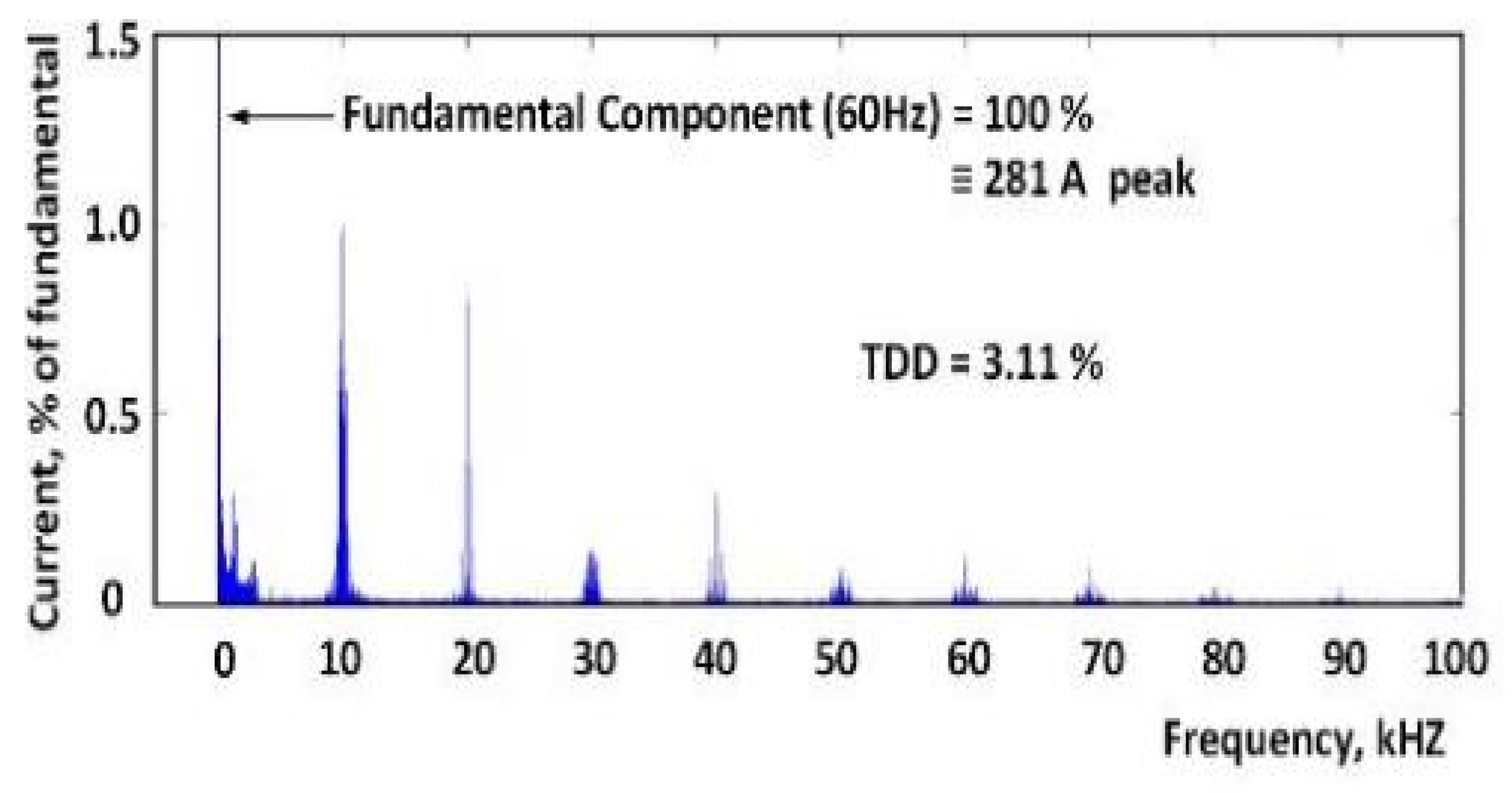
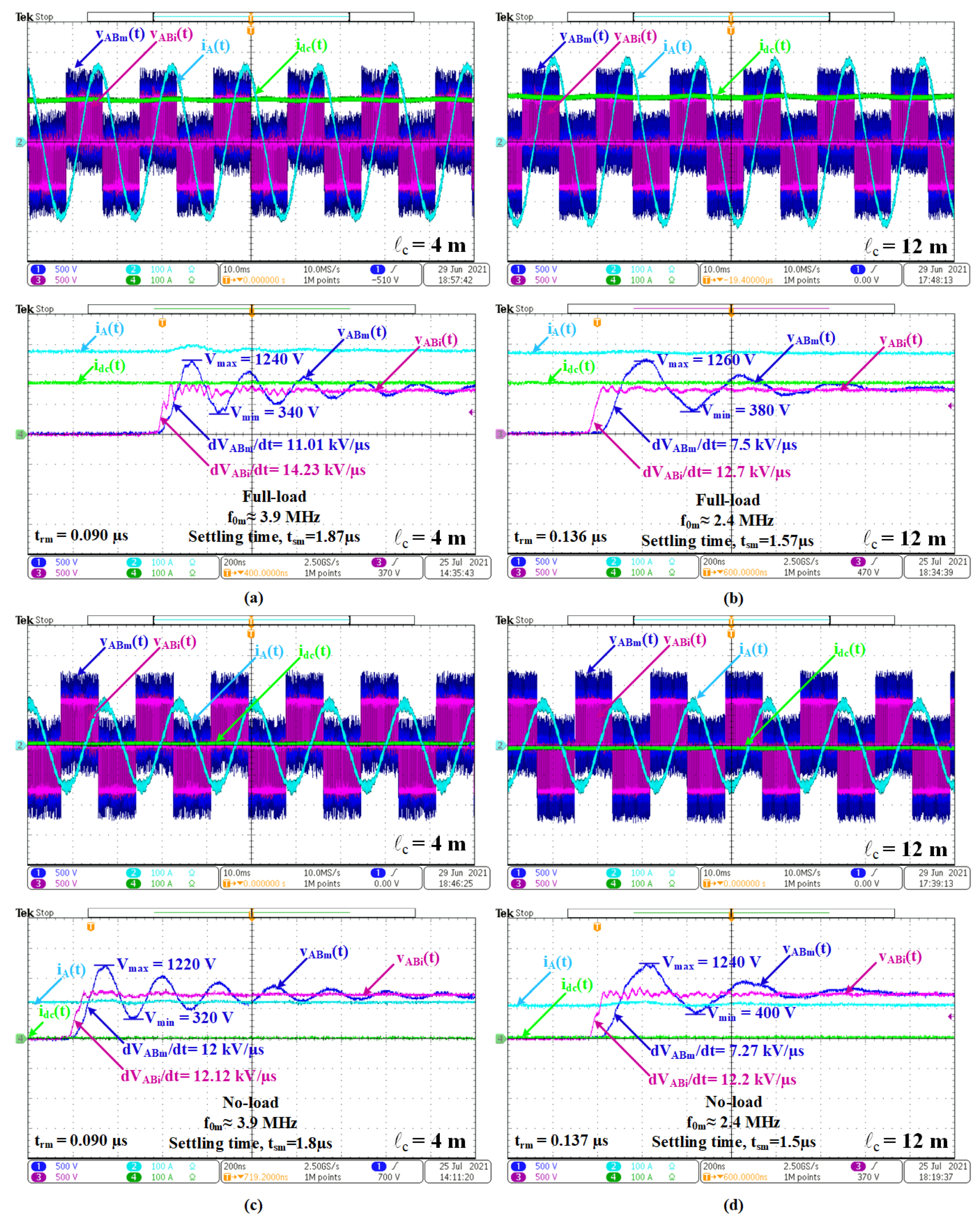
The motor line currents are nearly sinusoidal, e.g., iA(t);
(ii)
Although the fundamental components VAbi = VABm  480 V l-to-l rms, the first peak of VABi(t) 780–810 is enhanced to VABm = 1240 V for lc = 4 and 1260 V for lc = 12 m;
(iii)
The frequency of oscillation in the line-to-line voltage waveform is lower for longer cables with a shorter settling time;
(iv)
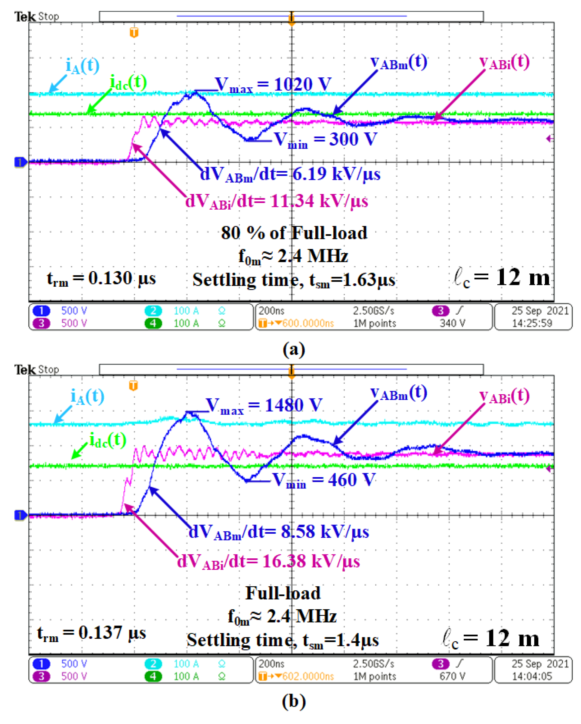
The dv/dt of each pulse in the line-to-line PWM voltage waveform at the output of the inverter is usually higher than 10 kV/µs. The cables connecting the inverter to the motor lower these high dv/dts usually to below 10 kV/µs;
(v)
Similar conclusions can also be drawn for no-load operations;
(vi)
For the application described in this paper, a cable length of around 12 m is more useful than shorter cables, such as 4 m in length.
Since the catenary voltage varies in a wide range, as illustrated in Appendix A, records corresponding to Figure 25b for lc = 12 m were obtained from the developed system and are shown in Figure 26a,b respectively for Vdc = 600 V and 900 V.
As can be understood from Figure 25 and Figure 26, the first voltage peaks in the pulses of the VABi(t) and VABm(t) and the corresponding dvABi(t)/dt and dvABm(t)/dt values became higher and higher as the catenary voltage, Vdc, increased. The limiting curve of the admissible impulse voltage for the industrial induction motors is recommended in [42] (Figure 40 of [42]) and was partly redrawn by extrapolating the data from trm = 0.1 to 0.05 µs, as shown in Appendix D. This standard defines the area under the blue-colored curve as the safe operating area for the induction motor.
In this research work, the rise time, trm, of the line-to-line voltage pulses at the stator terminals was measured to be 90 ns in the worst case (lc = 4 m). Since the V ^ m l-to-l/Vm l-to-l (rated) ≅ 2 for trm = 90 ns and Vm l-to-l (rated) = 480 V rms, the maximum recommended peak value of the impulse voltage was calculated to be 2 × 480 = 960 V. However, the V ^ m l-to-l was measured to be 1240 V (Figure 25a), which is much higher than the maximum recommended value of 960 V. On the other hand, the maximum permissible value of dvABm/dt is recommended to be 10 kV/µs by the traction motor manufacturer. The permissible dvABm/dt curve can be calculated from the V ^ m l-to-l/Vm l-to-l (rated) curve for Vm l-to-l (rated) = 480 V and different trm values. The resulting characteristics are marked in Figure A3 in Appendix D. Although its value was calculated to be nearly 10 kV/µs, its actual value was measured to be 11 kV/µs (Figure 25a) while dvABm/dt = 8.58 kV/µs (Figure 25b) for lc = 12 m, which is safe.
However, in the practical applications of SiC power MOSFET-based traction converters, the trm may be lower, e.g., 50 ns, and the cable may be shorter, lc = 3–4 m, which would result in dvABm/dt values considerably higher than 10 kV/µs.
In view of the above findings, the following conclusions can be made:
(a)
Insulation systems may be enhanced in future traction motors for use with SiC power MOSFET-based traction converters at the expense of a higher cost; and/or
(b)
Specially-designed active gate driver circuits may be used at the expense of marginally higher switching losses [43,44,45,46].
Presently, [47] recommends one of the following techniques to reduce the dvABm/dt in industrial motors fed by PWM converters, the switching frequencies of which are about 2.5 kHz: (i) output reactors, (ii) dv/dt filter, (iii) sinusoidal filter, and (iv) electrical machine termination unit. These techniques reduce the dvABm/dt values in Si-IGBT-based traction converters below 1 kV/µs at the expense of a 0.5–1% drop in the efficiency of the traction motor drive.

7. Conclusions and Future Work

The design and development of a high-performance, all-SiC, 165 kVA traction motor drive for light rail transportation systems, based on two-quadrant operating characteristics of the drive and a complete mathematical model of the public transportation vehicle, have been described. In the design phase, the performances of two-level traction converters supplied by 750 V DC catenary lines and equipped with different new-generation power semiconductors, such as a SiC power MOSFET, Si-IGBT, and hybrid IGBT of compatible ratings, were compared in view of their thermal behaviors, switching and conduction losses, and optimum switching frequencies by carrying out detailed computer simulations. The SiC power MOSFET was shown to outperform the hybrid and Si-IGBT alternatives, with a further advantage of conducting the reverse current, thus reducing the conduction loss at relatively high operating powers. In most advanced traction motor drives, Si power semiconductors are being used where the maximum attainable carrier frequency could be set to 21 f s m a x = 3255 Hz in order to obtain a reasonably low TDD for the motor line currents. However, in this research work, the use of SiC power MOSFETs with a much higher switching frequency of fC = 10 kHz provided a faster drive response and much lower TDD in comparison to those of the alternative Si converters. The optimum switching frequency region was determined to be 10 to 17.5 kHz to maximize the traction motor drive efficiency at the rated operating conditions, i.e., the inverter efficiency times the motor efficiency. In addition to the considerably low TDD of 3.11%, a very high operating efficiency of 91.7% was obtained for the induction traction motor drive under rated operating conditions at fC = 10 kHz. The SiC inverter efficiency was obtained as 98.7% and the motor efficiency as 92.9% at the rated conditions, as compared to the Si-IGBT-based traction motor drive with 98% inverter efficiency and 91.5% motor efficiency, owing to the current harmonic distortion. This amounts to nearly 3% higher system efficiency for the developed SiC traction motor drive as compared to the Si-IGBT-based ones. High currents, and hence, high torque bandwidths, arising from a high switching frequency permit the application of SVPWM and FOC over the entire operating ranges of the stator frequency, output power, and catenary voltage. On the other hand, the qualitative objectives in the converter design, such as the simple converter topology, low complexity in the control algorithm, small size, and less audible noise, have been also successfully met by the use of SiC technology.
Most metro vehicles are supplied by 750 and 1500 V DC catenary lines. Regional trains, high-speed and very high-speed trains, and main-line locomotives are supplied by 15 or 25 kV AC single-phase overhead lines. This AC voltage level is converted to 1800–3000 V DC by on-board equipment. Furthermore, 1500 or 3000 V DC catenary lines are directly used by some other railway vehicles. For future work, it is recommended to illustrate the benefits of two-level traction converters by using 3300 V engineering prototypes of SiC power MOSFETs in such higher voltage and power applications. Alternatively, three-level traction converter topologies can be developed and tested in the near future by using the newly developed traction-type 1700 V higher-current SiC power MOSFETs.

Supplementary Materials

The following supporting information can be downloaded at https://www.mdpi.com/article/10.3390/electronics11091438/s1: Video S1: Video_MDPI_SiC_Traction_Motor_Drive.mp4.

Author Contributions

M.E. and I.Ç. conceptualized the presented idea. D.Y. developed and implemented the SiC traction motor drive. D.Y. and M.H.A. conducted the experimental tests. All authors have read and agreed to the published version of the manuscript.

Funding

The Traction Motor Drive Project 5150038 was fully financed by the Technology and Innovation Funding Programs Directorate of the Scientific and Technological Research Council of Turkey, TUBITAK TEYDEB and ASELSAN, Inc., and the Transportation, Security, Energy, Automation and Healthcare Systems Business Sector (Corresponding author: Muammer Ermis).

Conflicts of Interest

The authors declare no conflict of interest.

Appendix A

The permissible voltage variations in a 750 V DC catenary line are specified in [32] and were redrawn against time, as shown in Figure A1.
Figure A1. Permissible voltage variations in 750 V DC catenary line.
Electronics 11 01438 g0a1

Appendix B

The permissible operating ranges of a vehicle current against the catenary line voltage are specified in [37], and were reconstructed as shown in Figure A2.
Figure A2. Permissible operating ranges of vehicle current against catenary line voltage.
Electronics 11 01438 g0a2

Appendix C

Table A1. Thermal resistances of SiC MOSFET module in comparison with hybrid and Si-IGBT modules and different heatsink sizes.
Thermal Data All in K/WSi IGBT Module (FF300R17KE4P) InfineonSi IGBT Module (CM300DY-34T) MitsubishiSi IGBT & SiC SBD Hybrid Module (2MSI400VAE-170-53) Fuji ElectricSiC MOSFET Module (CAS300M17BM2) Wolfspeed/Cree
IGBTDiodeIGBTDiodeIGBTDiodeMOSFETDiode
Rth(j-c)--0.0440.0680.0330.070.0710.065
Rth(c-h)--0.03130.03130.0313
Rth(j-h)0.1140.117----
Rth(h-a) 00.018 *0.018 *0.018 *0.018 *
Rth(h-a) ‡0.013 †0.013 †0.013 †0.018 *
0 For comparison purpose; ‡ Optimum values; † Fischer Elektronik SK-661, W × H × L: 500 × 84 × 500 mm; v = 5 m/s forced-air cooling; * Fischer Elektronik SK-461, W × H × L: 400 × 84 × 400 mm; v = 5 m/s forced-air cooling.

Appendix D

Limiting curve in [42] (Figure 40 of [42]) was partly redrawn as shown in Figure A3.
Figure A3. Limiting curve in [42] (Figure 40 of [42]) and corresponding dv/dt curve for 480 V l-to-l-rated traction motor voltage as a function of the rise time, trm, of the voltage pulse at the electrical machine terminals.
Electronics 11 01438 g0a3

References

  1. Makishima, S.; Fujimoto, K.; Kondo, K. The Direct Benefit of SiC Power Semiconductor Devices for Railway Vehicle Traction Inverters. In Proceedings of the IEEE 2018 International Power Electronics Conference (IPEC-Niigata 2018-ECCE Asia), Niigata, Japan, 20–24 May 2018. [Google Scholar]
  2. Elasser, A.; Chow, T.P. Silicon Carbide Benefits and Advantages for Power Electronics Circuits and Systems. Proc. IEEE 2002, 90, 969–986. [Google Scholar] [CrossRef]
  3. Dong, D.; Lin, X.; Ravi, L.; Yan, N.; Burgos, R. Advancement of SiC High-frequency Power Conversion Systems for Medium-Voltage High-Power Applications. In Proceedings of the 2020 IEEE 9th International Power Electronics and Motion Control Conference (IPEMC2020-ECCE Asia), Nanjing, China, 29 November–2 December 2020; pp. 717–724. [Google Scholar]
  4. Nawaz, M.; Ilves, K. On the comparative assessment of 1.7 kV, 300 a full SiC-MOSFET and Si-IGBT power modules. In Proceedings of the 2016 IEEE Applied Power Electronics Conference and Exposition (APEC), Long Beach, CA, USA, 20–24 March 2016; pp. 276–282. [Google Scholar]
  5. Acharya, S.; She, X.; Datta, R.; Todorovic, M.H.; Mandrusiak, G. Comparison of 1.7 kV, 450 A SiC-MOSFET and Si-IGBT based modular three phase power block. In Proceedings of the 2017 IEEE Energy Conversion Congress and Exposition (ECCE), Cincinnati, OH, USA, 1–5 October 2017; pp. 5119–5125. [Google Scholar]
  6. Imaizumi, M.; Hasegawa, S.; Sumitani, H.; Iwasaki, M.; Hino, S.; Watanabe, T.; Hamada, K.; Miura, N.; Nakata, S.; Yamakawa, S. Remarkable Advances in SiC Power Device Technology for Ultra High Power Systems. In Proceedings of the 2013 IEEE International Electron Devices Meeting, Washington, DC, USA, 9–11 December 2013; pp. 6.5.1–6.5.4. [Google Scholar]
  7. Morya, A.K.; Gardner, M.C.; Anvari, B.; Liu, L.; Yepes, A.G.; Doval-Gandoy, J.; Toliyat, H.A. Wide Bandgap Devices in AC Electric Drives: Opportunities and Challenges. IEEE Trans. Transp. Electrif. 2019, 5, 3–20. [Google Scholar] [CrossRef]
  8. Gu, C.; Wang, X.; Deng, Z. Evaluation of Three Improved Space-Vector-Modulation Strategies for the High-Speed Permanent Magnet Motor Fed by a SiC/Si Hybrid Inverter. IEEE Trans. Power Electron. 2021, 36, 4399–4409. [Google Scholar] [CrossRef]
  9. Fabre, J.; Ladoux, P.; Piton, M. Characterization and Implementation of Dual-SiC MOSFET Modules for Future Use in Traction Converters. IEEE Trans. Power Electron. 2015, 30, 4079–4090. [Google Scholar] [CrossRef]
  10. Gaertner, M.; Cavallaro, D.; Pulvirenti, M.; Zanetti, E.; Saggio, M.; Ferrara, M. SiC MOSFETs as Enabler for the future ePowertrain and its behaviour under Short Circuit Condition. In Proceedings of the 2019 AEIT International Conference of Electrical and Electronic Technologies for Automotive (AEIT AUTOMOTIVE), Turin, Italy, 2–4 July 2019. [Google Scholar]
  11. Zhang, C.; Srdic, S.; Lukic, S.; Kang, Y.; Choi, E.; Tafti, E. A SiC-Based 100 kW High-Power-Density (34 kW/L) Electric Vehicle Traction Inverter. In Proceedings of the 2018 IEEE Energy Conversion Congress and Exposition (ECCE), Portland, OR, USA, 23–27 September 2018. [Google Scholar]
  12. Zhu, J.; Kim, H.; Chen, H.; Erickson, R.; Maksimovic, D. High Efficiency SiC Traction Inverter for Electric Vehicle Applications. In Proceedings of the 2018 IEEE Applied Power Electronics Conference and Exposition (APEC), San Antonio, TX, USA, 4–8 March 2018. [Google Scholar]
  13. Wu, Y.; Mahmud, M.H.; Allee, E.; Zhao, Y.; Mantooth, A. An Optimized Silicon Carbide based 2 × 250 kW Dual Inverter for Traction Applications. In Proceedings of the 2020 IEEE Applied Power Electronics Conference and Exposition (APEC), New Orleans, LA, USA, 15–19 March 2020. [Google Scholar]
  14. Bucher, A.; Schmidt, R.; Werner, R.; Leipenat, M.; Hasenohr, C.; Werner, T.; Schmitz, S.; Heitmann, A. Design of a Full SiC Voltage Source Inverter for Electric Vehicle Applications. In Proceedings of the 2016 18th European Conference on Power Electronics and Applications (EPE’16 ECCE Europe), Karlsruhe, Germany, 5–9 September 2016. [Google Scholar]
  15. Zhang, L.; Li, Y.; Zhang, Y.; Yuan, X.; Wang, Z.; Li, Z. A 100 kW Forced-Air-Cooled SiC MOSFET Converter Achieving a Power Density of 1.657 kW/L and an Efficiency over 98.5%. In Proceedings of the IEEE 9th International Power Electronics and Motion Control Conference (IPEMC2020-ECCE Asia), Nanjing, China, 29 November–2 December 2020. [Google Scholar]
  16. She, X.; Datta, R.; Todorovic, M.H.; Mandrusiak, G.; Dai, J.; Frangieh, T.; Cioffi, P.; Rowden, B.; Mueller, F. High Performance Silicon Carbide Power Block for Industry Applications. IEEE Trans. Ind. Appl. 2017, 53, 3738–3747. [Google Scholar] [CrossRef]
  17. Moorthy, R.S.K.; Aberg, B.; Olimmah, M.; Yang, L.; Rahman, D.; Lemmon, A.N.; Yu, W.; Husain, I. Estimation, Minimization, and Validation of Commutation Loop Inductance for a 135-kW SiC EV Traction Inverter. IEEE J. Emerg. Sel. Top. Power Electron. 2020, 8, 286–297. [Google Scholar] [CrossRef]
  18. Chou, W.; Kempitiya, A.; Vodyakho, O. Reduction of Power Losses of SiC MOSFET Based Power Modules in Automotive Traction Inverter Applications. In Proceedings of the 2018 IEEE Transportation Electrification Conference and Expo (ITEC), Long Beach, CA, USA, 10–15 June 2018. [Google Scholar]
  19. Yang, L.; Luo, Y.; Moorthy, R.S.K.; Rahman, D.; Yu, W.; Husain, I. Design and Test of a Planarized High Power Density 100 kW SiC Traction Inverter with 1kV DC-Link. In Proceedings of the 2018 IEEE Energy Conversion Congress and Exposition (ECCE), Portland, OR, USA, 23–27 September 2018. [Google Scholar]
  20. Yu, S.; Wang, J.; Zhang, X.; Liu, Y.; Jiang, N.; Wang, W. The Potential Impact of Using Traction Inverters with SiC MOSFETs for Electric Buses. IEEE Access 2021, 9, 51561–51572. [Google Scholar] [CrossRef]
  21. Salem, T.E.; Wood, R.A. 1000-H Evaluation of a 1200-V, 880-A All-SiC Dual Module. IEEE Trans. Power Electron. 2014, 29, 2192–2198. [Google Scholar] [CrossRef]
  22. Ladoux, P.; Mermet, M.; Casarin, J.; Fabre, J. Outlook for SiC devices in Traction Converters. In Proceedings of the 2012 Electrical Systems for Aircraft, Railway and Ship Propulsion, Bologna, Italy, 16–18 October 2012. [Google Scholar]
  23. Li, X.; Li, D.; Chang, G.; Gong, W.; Packwood, M.; Pottage, D.; Wang, Y.; Luo, H.; Liu, G. High-Voltage Hybrid IGBT Power Modules for Miniaturization of Rolling Stock Traction Inverters. IEEE Trans. Ind. Electron. 2021, 69, 1266–1275. [Google Scholar] [CrossRef]
  24. Soltau, N.; Wiesner, E.; Stumpf, E.; Idaka, S.; Hatori, K. Electric-Energy Savings using 3.3 kV Full-SiC Power-Modules in Traction Applications. In Proceedings of the 2020 15th International Conference on Ecological Vehicles and Renewable Energies (EVER), Monte-Carlo, Monaco, 10–12 September 2020. [Google Scholar]
  25. Yıldırım, D.; Akşit, M.H.; Yolaçan, C.; Pul, T.; Ermiş, C.; Aghdam, B.H.; Çadırcı, I.; Ermiş, M. Full-Scale Physical Simulator of All SiC Traction Motor Drive with Onboard Supercapacitor ESS for Light-Rail Public Transportation. IEEE Trans. Ind. Electron. 2020, 67, 6290–6301. [Google Scholar] [CrossRef]
  26. Sato, K.; Kato, H.; Fukushima, T. Development of SiC Applied Traction System for Shinkansen High-speed Train. In Proceedings of the 2018 International Power Electronics Conference (IPEC-Niigata 2018-ECCE Asia), Niigata, Japan, 20–24 May 2018. [Google Scholar]
  27. Li, D.; Li, X.; Chang, G.; Qi, F.; Packwood, M.; Pottage, D.; Wang, Y.; Luo, H.; Dai, X.; Liu, G. Characterization of a 3.3-kV Si-SiC Hybrid Power Module in Half-Bridge Topology for Traction Inverter Application. IEEE Trans. Power Electron. 2020, 35, 13429–13440. [Google Scholar] [CrossRef]
  28. Liang, T.; Liu, Q.; Dinavahi, V.R. Real-Time Hardware-in-the-Loop Emulation of High-Speed Rail Power System with SiC-Based Energy Conversion. IEEE Access 2020, 8, 122348–122359. [Google Scholar] [CrossRef]
  29. Liang, H.; Wenqing, M.; YuLiang, W.; Yongcan, L.; Xiangyu, F.; Yan, J. Experimental Study of the PWM Control Strategy For SiC Traction Inverter of Metro Vehicles. In Proceedings of the 2020 IEEE Vehicle Power and Propulsion Conference (VPPC), Gijon, Spain, 18 November–16 December 2020; pp. 1–5. [Google Scholar]
  30. Merkert, A.; Krone, T.; Mertens, A. Characterization and Scalable Modeling of Power Semiconductors for Optimized Design of Traction Inverters with Si- and SiC-Devices. IEEE Trans. Power Electron. 2014, 29, 2238–2245. [Google Scholar] [CrossRef]
  31. Wang, Q.; Zhang, Y.; Li, C.; Li, W.; He, X. Comprehensive Comparison between Two-Level, Three-Level, and Hybrid Three-Level SiC Inverter for High Power High Speed Drive System. In Proceedings of the IEEE 9th International Power Electronics and Motion Control Conference (IPEMC2020-ECCE Asia), Nanjing, China, 29 November–2 December 2020; pp. 1884–1889. [Google Scholar]
  32. European Standard BS EN 50163; Railway Applications-Supply Voltages of Traction Systems. European Committee for Electrotechnical Standardization: Brussel, Belgium, 2004.
  33. Mohan, N.; Undeland, T.M.; Robbins, W.P. Power Electronics: Converters, Applications, and Design; John Wiley & Sons: Hoboken, NJ, USA, 2003. [Google Scholar]
  34. Thomas, A.P.; Holmes, D.G. Pulse Width Modulation for Power Converters; John Wiley & Sons: Hoboken, NJ, USA, 2003. [Google Scholar]
  35. Infineon AN2019-05. Available online: https://www.infineon.com/dgdl/Infineon-AN2019-05_PC_and_TC_Diagrams-ApplicationNotes-v02_01-EN.pdf?fileId=5546d46269e1c019016a594443e4396b (accessed on 26 March 2022).
  36. Comparison Between Ce Alloys and Competitive Materials. Available online: https://www.materials.sandvik/da-dk/produkter/ce-alloys/comparsion-with-competitive-materials/ (accessed on 16 March 2022).
  37. BS EN 50388; Railway Applications-Power Supply and Rolling Stock—Technical Criteria for the Coordination between Power Supply (Substation) and Rolling Stock to Achieve Interoperability. ISO: London, UK, 2012.
  38. Buhrkall, L. Traction System Case Study, Traction Systems and EMC, Denmark. Available online: https://ieeexplore.ieee.org/document/4760166/authors#authors (accessed on 16 March 2022).
  39. Youssef, M.; Abu-Qahouq, J.; Orabi, M. The electromagnetic compatibility design considerations of the input filter of a 3-phase inverter in a railway traction system. In Proceedings of the 2010 IEEE Energy Conversion Congress and Exposition, Atlanta, GA, USA, 12–16 December 2010; pp. 4210–4216. [Google Scholar]
  40. Abad, G. Power Electronics and Electric Drives for Traction Applications; John Wiley & Sons, Inc.: Chichester, UK, 2017. [Google Scholar]
  41. Apparatus, European Standard EN50121-3-2; Railway Applications—Electromagnetic Compatibility Rolling Stock. European Committee for Electrotechnical Standardization: Brussel, Belgium, 2015.
  42. European Standard IEC TS 60034-25; Rotating Electrical Machines—Part 25: Guidance for the Design and Performance of a.c. Motors Specifically Designed for Converter Supply. International Electrotechnical Commission: Geneva, Switzerland, 2014.
  43. Wei, Y.; Du, X.; Woldegiorgis, D.; Mantooth, A. Application of An Active Gate Driver for Paralleling Operation of Si IGBT and SiC MOSFET. In Proceedings of the IEEE 12th Energy Conversion Congress & Exposition—Asia (ECCE-Asia), Singapore, 24–27 May 2021; pp. 314–319. [Google Scholar]
  44. Wang, M.; Zhang, W.J.; Liang, J.; Cui, W.T.; Ng, W.T.; Nishio, H.; Sumida, H.; Nakajima, H. A Smart Gate Driver for SiC Power MOSFETs with Aging Compensation and Ringing Suppression. In Proceedings of the 2021 33rd International Symposium on Power Semiconductor Devices and ICs (ISPSD), Nagoya, Japan, 30 May–3 June 2021; pp. 67–70. [Google Scholar]
  45. Lu, Y.; Yao, W. An Active Gate Driver Design to Reduce Voltage and Current Overshoots for SiC MOSFET Modules. In Proceedings of the IEEE 9th International Power Electronics and Motion Control Conference (IPEMC2020-ECCE Asia), Nanjing, China, 29 November–2 December 2020; pp. 915–920. [Google Scholar]
  46. Wu, H.; Wang, X.; Ortiz-Gonzalez, J.; Alatise, O.; Pickert, V. Investigation into the Switching Transient of SiC MOSFET Using Voltage/Current Source Gate Driver. In Proceedings of the 10th International Conference on Power Electronics, Machines and Drives (PEMD 2020), Online Conference, 15–17 December 2020; pp. 657–662. [Google Scholar]
  47. European Standard BS EN 60034-18-41; Rotating Electrical Machines Partial Discharge Free Electrical Insulation Systems (Type I) Used in Electrical Rotating Machines Fed from Voltage Converters. Qualification and Quality Control Tests. European Committee for Standards: Brussel, Belgium, 2019.
Figure 1. Circuit diagram of a three-phase voltage-source traction motor converter for light rail public transportation systems.
Electronics 11 01438 g001
Figure 2. Operating characteristics of the traction motor drive for forward motion. (a) Speed/torque characteristics; (b) speed/shaft power.
Electronics 11 01438 g002
Figure 3. Electrical connection diagram of CAS300M17BM2 SiC power MOSFET module. (a) Electrical connection diagram (the two MOSFET chips and their anti-parallel SiC Schottky diodes are labeled as in the first leg of the traction converter in Figure 1); (b) the associated all-SiC half-bridge module. (1) Common source/drain point, (2) Source, (3) Drain, (4,6) Gate, (5,7) Kelvin source.
Electronics 11 01438 g003
Figure 4. Current waveforms of S1, D1, S4, and D4 in Figure 3a, obtained by MATLAB/Simulink when the traction inverter is supplied with 750 V DC and applies 480 V l-to-l at 60 Hz to the stator. (a,b) Si-IGBT-based converter supplies 173 kVA at 0.81 pf; (c,d) SiC power MOSFET-based converter supplies 173 kVA at 0.81 pf, and (e,f) SiC power MOSFET-based converter supplies 75 kVA at 0.29 pf.
Electronics 11 01438 g004
Figure 5. Application of SVPWM to the traction converter of LRTS described in this paper.
Electronics 11 01438 g005
Figure 6. Hexagons containing colored discs represent variable speed operating regions bounded by (a) Vdc (min) = 600 V (Mi = 1 can give only 424 V l-to-l), (b) Vdc (rated) = 750 V (Mi = 0.9 to give 480 V l-to-l), and (c) Vdc (max) = 900 V (Mi = 0.75 to give 480 V l-to-l).
Electronics 11 01438 g006
Figure 7. Block diagram of the digital control system with space vector PWM, active damping, and field-oriented control.
Electronics 11 01438 g007
Figure 8. Transfer characteristics of the input power filter and digital notch filter plotted against the same frequency range.
Electronics 11 01438 g008
Figure 9. The developed all-SiC power MOSFET-based traction converter. (a) Front view, (b) top view, and (c) traction motor-loading generator set.
Electronics 11 01438 g009
Figure 10. Power stage of traction converter. (a) Top layer, (b) third layer, (c) second layer, (d) bottom layer.
Electronics 11 01438 g010
Figure 11. Variations in total power loss components of the traction motor at no-load against switching frequency of the inverter when Vdc = 750 V, Vs = 480 V l-to-l, fs = 60 Hz, and nr = 1800 rpm.
Electronics 11 01438 g011
Figure 12. Variations in total power loss components of the traction inverter against switching frequency when Vdc = 750 V, Vs = 480 V l-to-l, fs = 60 Hz, and nr = 1779 rpm in delivering 165 kVA to the motor at 0.81 pf lag.
Electronics 11 01438 g012
Figure 13. Total power loss of the traction motor drive, Ptot, against switching frequency, fsw, when Vdc = 750 V, Vs = 480 V l-to-l, fs = 60 Hz, and nr = 1779 rpm in delivering 125 kW to its load.
Electronics 11 01438 g013
Figure 14. Input DC current, Idc, and DC link voltage, Vdc, and AC output voltage, vAB, and current, iA, waveforms corresponding to fs = 60 Hz, fsw = 10 kHz as recorded by Tektronix MDO3034 oscilloscope at a sampling rate of 1 MS/s/channel while (a) the traction inverter is delivering 165 kVA to the traction motor at Vdc = 765 V, and (b) the traction inverter is delivering 169 kVA to the traction motor at Vdc = 900 V.
Electronics 11 01438 g014
Figure 15. Harmonic components of the line currents up to the 50th were obtained by three-phase, three-wire connection for the operating conditions in Figure 14a.
Electronics 11 01438 g015
Figure 16. Fourier series expansion of recorded iA(t) waveform in Figure 14a obtained from MATLAB/Simulink FFT toolbox.
Electronics 11 01438 g016
Figure 17. Percent efficiency of traction inverter against traction motor input kVA at rated speed of 1779 rpm when Vdc = 750 V, VAB = 480 V rms, and fs = 60 Hz.
Electronics 11 01438 g017
Figure 18. Snapshots of output DC link current, Idc, and DC link voltage, Vdc, and AC input voltage, vAB, and current, iA, waveforms corresponding to fs = 60 Hz, fsw = 10 kHz as recorded by Tektronix MDO3034 oscilloscope at a sampling rate of 1 MS/s/channel while traction motor drive is operating in regenerative braking mode. (a) The traction converter operating in the rectification mode absorbs 168 kVA at 0.82 pf from the traction motor operating in the generation mode and delivers 138 kW to the DC link at Vdc = 765 V, and (b) the traction converter operating in the rectification mode absorbs 165 kVA at 0.82 pf from the traction motor operating in the generation mode and delivers 135 kW to the DC link at Vdc = 900 V.
Electronics 11 01438 g018
Figure 19. The variations in instantaneous efficiency of the traction converter during regenerative braking mode as a function of input kVA.
Electronics 11 01438 g019
Figure 20. Switching waveforms of 1700 V, 325 A high-side SiC Power MOSFET in phase A of the traction converter. (a) Turn-on, (b) turn-off.
Electronics 11 01438 g020
Figure 21. Acceleration, constant speed operation, and then deceleration on a level track Region 1: Starting period, Region 2: Acceleration at maximum torque, Region 3: Acceleration at constant power, Region 4: Controller action for smooth transition from acceleration to constant speed operation, Region 5: Constant speed operation, Region 6: Start of regenerative braking operation, Region 7: Deceleration at constant power, Region 8: Deceleration under maximum braking torque, Region 9: Bringing the vehicle to a stop by mechanical brake.
Electronics 11 01438 g021
Figure 22. Acceleration and then constant speed operation on a track with a positive maximum slope. Region 1: Starting period, Region 2: Acceleration at maximum torque, Region 3: Acceleration at constant power, Region 4: Controller action for smooth transition from acceleration to constant speed operation, Region 5: Constant speed operation.
Electronics 11 01438 g022
Figure 23. Constant speed operation and then deceleration by regenerative braking while going downhill. Region 1: Constant speed operation, Region 2: Start of regenerative braking operation, Region 3: Deceleration at constant power, Region 4: Deceleration under maximum braking torque, Region 5: Bringing the vehicle to a stop by mechanical brake.
Electronics 11 01438 g023
Figure 24. Experimental setup to test the effects of cable length on the system performance.
Electronics 11 01438 g024
Figure 25. Effects of motor cable length on line-to-line motor voltages. (a) 4 m cable length at full load, (b) 12 m cable length at full load, (c) 4 m cable length at no load, (d) 12 m cable length at no load.
Electronics 11 01438 g025
Figure 26. Effects of catenary voltage, Vdc, on line-to-line motor voltages. (a) Vdc = 600 V and at 80% of full load and (b) Vdc = 900 V and full load.
Electronics 11 01438 g026
Table 1. Technical specifications of the vehicle system and its rail track.
ParameterValues
Vehicle body structure5 Cars, M + T + T + T + M
Number of traction motors, m4
New wheel radius, r300 mm
Gear ratio, n7.5
Maximum slope8.5%
Maximum speed50 km/h
Acceleration up to 35 km/h1.2 m/s2 max.
Deceleration from 50 km/h1.3 m/s2 max.
Jerk limit1.0 m/s3
Vehicle mass, M39 tons unloaded (AW0)
56 tons loaded (AW3)
58 tons fully loaded (AW4)
Jgb+Jw182 kg-m2
A
B
C
D
Curve radius, R
0.0405 m/s2
0.0023 s−1
3.81 kg/m
0.053 m
30 m (Minimum)
Table 2. Technical specifications of traction motor.
Traction Motor
(VEM–DKCBZ 0212-4)
4-Pole, 60 Hz, 475 V, 125 kW, 0.81 pf (S1), η = 93.5%
Rated Torque671 Nm
Rated Speed1779 rpm
Max. Torque940 Nm
Max. Speed
Jm
5100 rpm
0.67 kg-m2
Vehicle Demand per Motor for the Chosen Track
Average Torque500 Nm
Average Speed1500 rpm
Average Power80 kW
Max. Torque943 Nm
Max. Speed2250 rpm
Max. Power128 kW
Table 3. Quantification of all operating points in Figure 2.
Operating Points in
Figure 2
Stator Freq. (Hz)Shaft Speed (rpm)Converter Output Power (kVA)Stator
Voltage
V l-to-l
Motor Output Power
(kW)
A601779165 at 0.81 pf lag480125
B601774185 at 0.81 pf lag140
C1043079170 at 0.89 pf lag140
D1554604154 at 0.88 pf lag125
E1554604176 at 0.81 pf lag154
F581779172 at 0.83 pf lag154
Table 4. Minimum values of carrier frequency against stator frequency for the operating characteristics in Figure 2 for the traditional design of Si-IGBT-based converters.
Stator Frequency, fS (Hz)Carrier Frequency, fC (Hz)
AdjustableConstant
1012603255
3012603255
6012603255
10021003255
15532553255
Publisher’s Note: MDPI stays neutral with regard to jurisdictional claims in published maps and institutional affiliations.

