
Development of an Enhanced Selective Harmonic Elimination for a Single-Phase Multilevel Inverter with Staircase Modulation


Abstract
:1. Introduction
2. Methodology
2.1. Conventional SHE
2.2. Development of the THD Reduction Constraint
2.3. Problem Formulation
3. Analysis of Theoretical Development
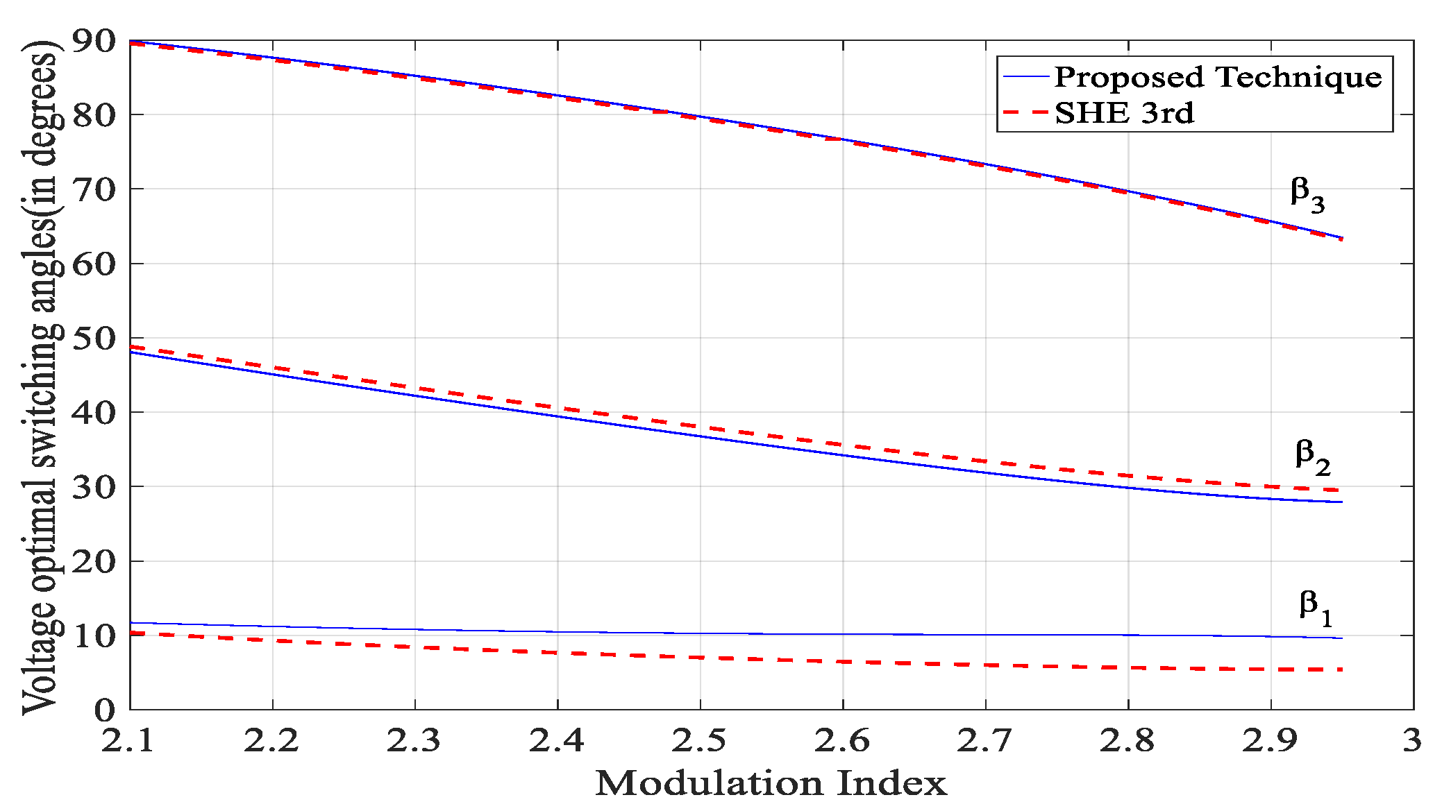
3.1. Third Order Harmonic Elimination
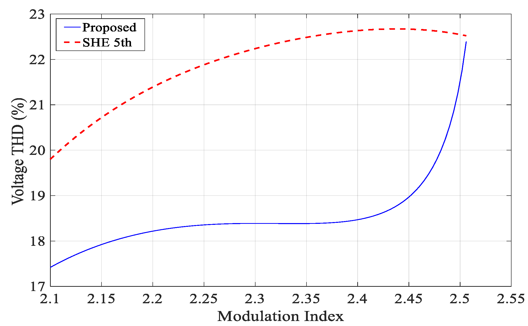
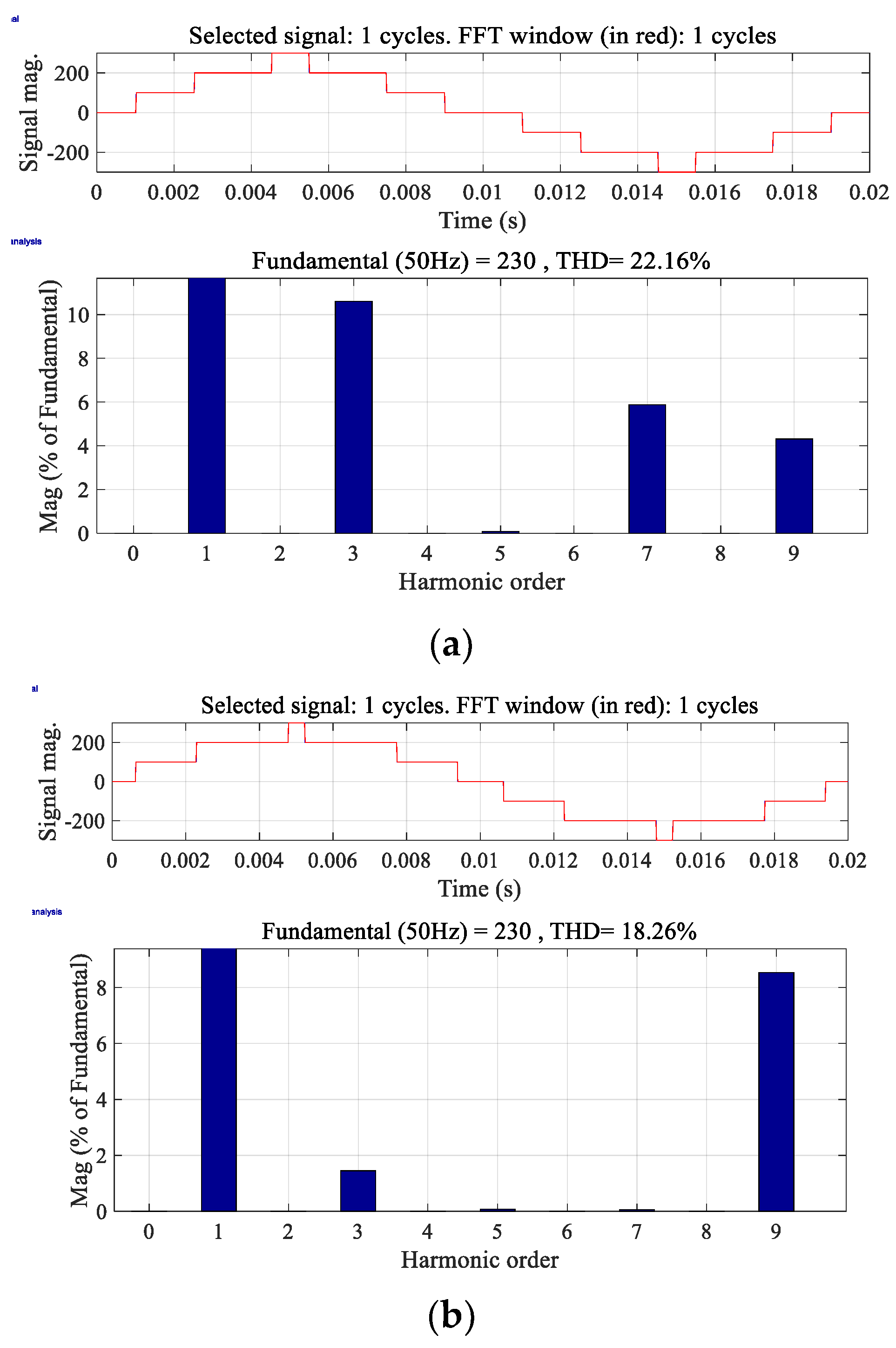
3.2. Fifth Order Harmonic Elimination
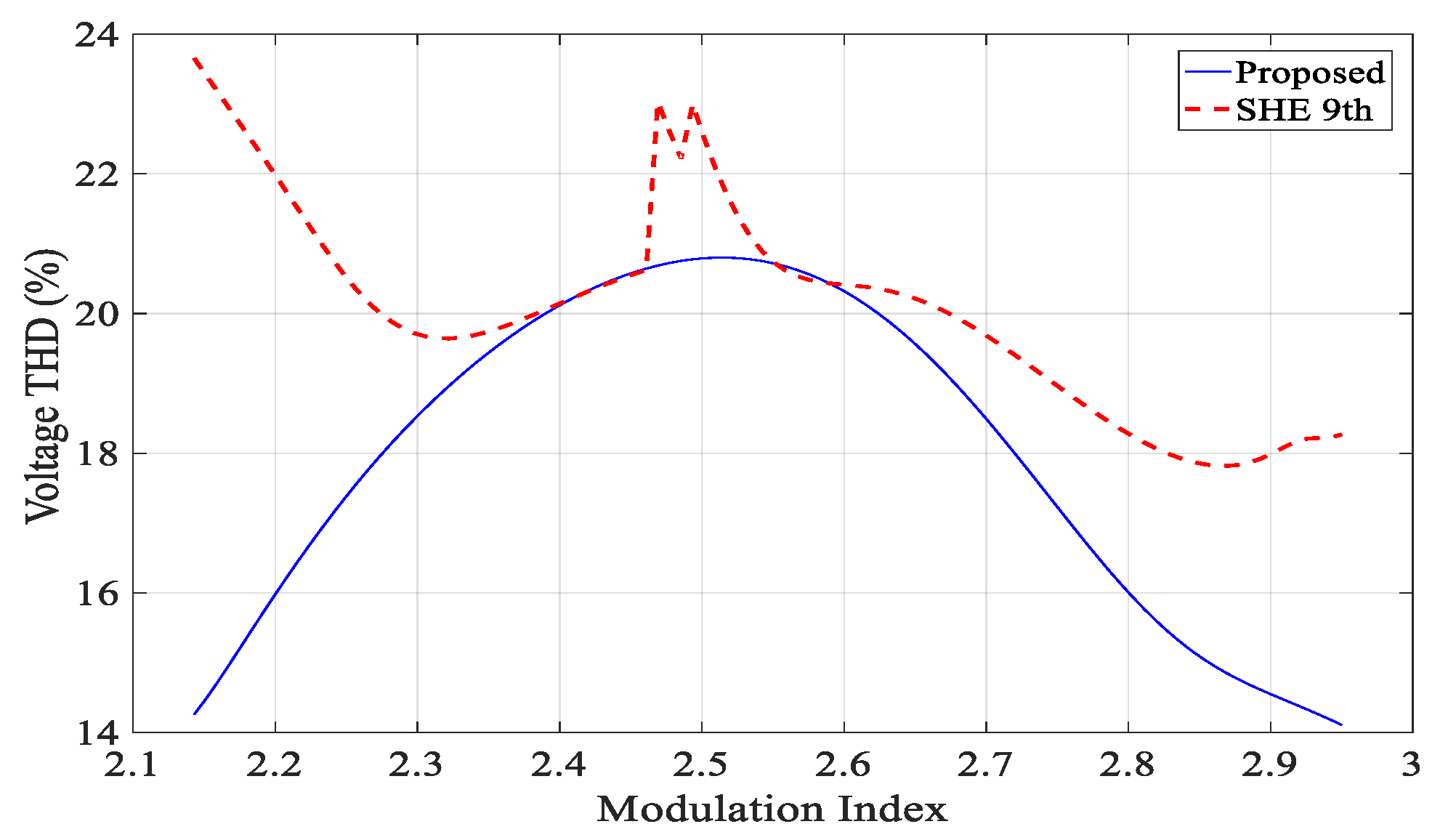
3.3. Ninth Order Harmonic Elimination
4. Simulation Results
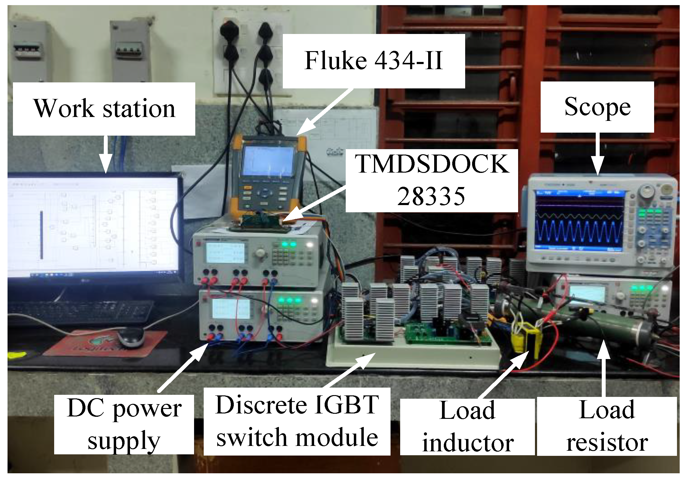
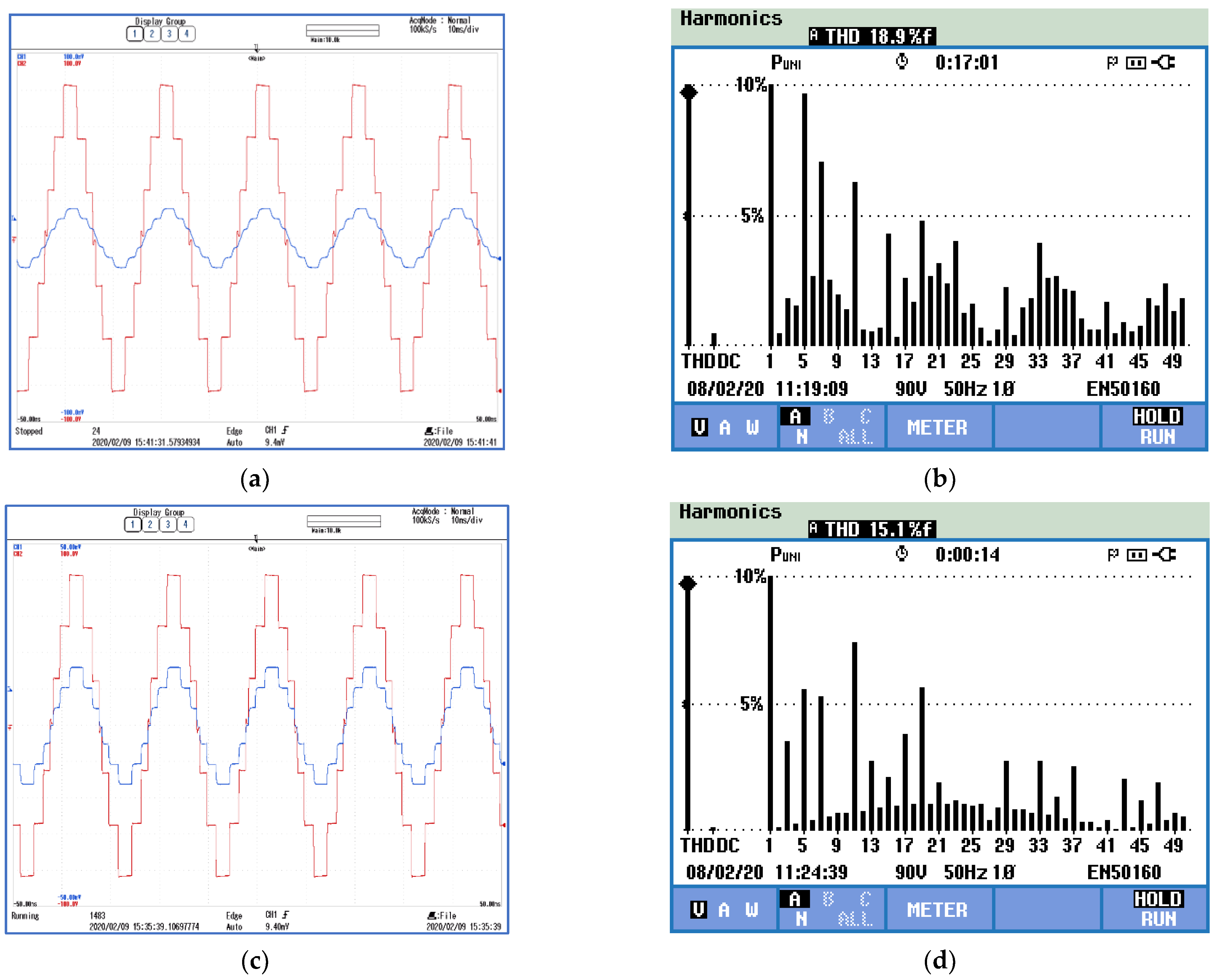
5. Experimental Verification
6. Conclusions
Author Contributions
Funding
Conflicts of Interest
References
- Ustun, T.S.; Hashimoto, J.; Otani, K. Impact of Smart Inverters on Feeder Hosting Capacity of Distribution Networks. IEEE Access 2019, 7, 163526–163536. [Google Scholar] [CrossRef]
- Baker, R.H.; Bannister, L.H. Electric Power Converter. US3867643A, 18 February 1975. pp. 1–17. [Google Scholar]
- Rodríguez, J.; Member, S.; Lai, J.; Member, S. Multilevel Inverters: A Survey of Topologies, Controls, and Applications. IEEE Trans. Ind. Electron. 2002, 49, 724–738. [Google Scholar] [CrossRef] [Green Version]
- Lai, J.; Peng, F.Z. Multilevel converters-a new breed of power converters. IEEE Trans. Ind. Appl. 1996, 32, 509–517. [Google Scholar]
- Tolbert, L.M.; Peng, F.Z.; Habetler, T.G. Multilevel converters for large electric drives. IEEE Trans. Ind. Appl. 1999, 35, 36–44. [Google Scholar] [CrossRef] [Green Version]
- Buccella, C.; Cecati, C.; Cimoroni, M.G.; Razi, K. Analytical method for pattern generation in five-level cascaded H-bridge inverter using selective harmonic elimination. IEEE Trans. Ind. Electron. 2014, 61, 5811–5819. [Google Scholar] [CrossRef]
- Mora, A.; Lezana, P.; Juliet, J. Control scheme for an induction motor fed by a cascade multicell converter under internal fault. IEEE Trans. Ind. Electron. 2014, 61, 5948–5955. [Google Scholar] [CrossRef]
- Edpuganti, A.; Rathore, A.K. Fundamental Switching Frequency Optimal Pulsewidth Modulation of Medium-Voltage Cascaded Seven-Level Inverter. IEEE Trans. Ind. Appl. 2015, 51, 3485–3492. [Google Scholar] [CrossRef]
- Tarisciotti, L.; Zanchetta, P.; Watson, A.; Bifaretti, S.; Clare, J.C. Modulated model predictive control for a seven-level cascaded h-bridge back-to-back converter. IEEE Trans. Ind. Electron. 2014, 61, 5375–5383. [Google Scholar] [CrossRef]
- Tang, T.; Han, J.; Tan, X. Selective harmonic elimination for a cascade multilevel inverter. In Proceedings of the 2006 IEEE International Symposium on Industrial Electronics, Montreal, QC, Canada, 9–13 July 2006; Volume 2, pp. 977–981. [Google Scholar]
- Haghdar, K. Optimal DC Source Influence on Selective Harmonic Elimination in Multilevel Inverters Using Teaching-Learning Based Optimization. IEEE Trans. Ind. Electron. 2019, 46, 1. [Google Scholar] [CrossRef]
- Inverters, S.F. Self-Elimination of Triplen Harmonics for. IEEE Trans. Power Electron. 2019, 34, 86–96. [Google Scholar]
- Chiasson, J.N.; Tolbert, L.M.; McKenzie, K.J.; Du, Z. Elimination of Harmonics in a Multilevel Converter Using the Theory of Symmetric Polynomials and Resultants. IEEE Trans. Control Syst. Technol. 2005, 13, 216–223. [Google Scholar] [CrossRef]
- Du, Z.; Member, S.; Tolbert, L.M.; Member, S.; Chiasson, J.N.; Member, S. Active Harmonic Elimination for Multilevel Converters. IET Power Electron. 2006, 21, 459–469. [Google Scholar]
- Dahidah, M.S.A.; Konstantinou, G.; Agelidis, V.G. A Review of Multilevel Selective Harmonic Elimination PWM: Formulations, Solving Algorithms, Implementation and Applications. IEEE Trans. Power Electron. 2015, 30, 4091–4106. [Google Scholar] [CrossRef]
- Wells, J.; Nee, B.; Chapman, P.; Krein, P. Selective Harmonic Control: A General Problem Formulation and Selected Solutions. IEEE Trans. Power Electron. 2005, 20, 1337–1345. [Google Scholar] [CrossRef]
- Sharifzadeh, M.; Member, S.; Vahedi, H.; Member, S. New Constraint in SHE-PWM for Single-Phase Inverter Applications. IEEE Trans. Ind. Appl. 2018, 54, 4554–4562. [Google Scholar] [CrossRef]
- Li, Y.; Zhang, X.-P.; Li, N. An Improved Hybrid PSO-TS Algorithm for Solving Nonlinear Equations of SHEPWM in Multilevel Inverters. IEEE Access 2022, 10, 48112–48125. [Google Scholar] [CrossRef]
- Farooqui, S.A.; Shees, M.M.; Alsharekh, M.F.; Alyahya, S.; Khan, R.A.; Sarwar, A.; Khan, S. Crystal Structure Algorithm (CryStAl) Based Selective Harmonic Elimination Modulation in a Cascaded H-Bridge Multilevel Inverter. Electronics 2020, 10, 3070. [Google Scholar] [CrossRef]
- Steczek, M.; Jefimowski, W.; Szeląg, A. Application of grasshopper optimization algorithm for selective harmonics elimination in low-frequency voltage source inverter. Energies 2020, 13, 6426. [Google Scholar] [CrossRef]
- Memon, M.A.; Mekhilef, S.; Mubin, M. Selective harmonic elimination in multilevel inverter using hybrid APSO algorithm. IET Power Electron. 2018, 11, 1673–1680. [Google Scholar] [CrossRef]
- Rai, N.; Chakravorty, S. Generalized formulations and solving techniques for selective harmonic elimination PWM strategy: A review. J. Inst. Eng. 2019, 100, 649–664. [Google Scholar] [CrossRef]
- Short, T.A. Electric Power Distribution Handbook; CRC Press: Boca Raton, FL, USA, 2014. [Google Scholar]
- Hoft, R.G. Generalized Techniques of Harmonic Elimination and Voltage Control in Thyristor Inverters: Part I—Harmonic Elimination. IEEE Trans. Ind. Appl. 1973, 3, 210–317. [Google Scholar]
- Patel, H.S.; Hoft, R.G. Generalized techniques of harmonic elimination and voltage control in thyristor inverters part II—Voltage control techniques. IEEE Trans. Ind. Appl. 1974, IA-10, 666–673. [Google Scholar] [CrossRef]
- Srndovic, M.; Familiant, Y.L.; Grandi, G.; Ruderman, A. Time-Domain Minimization of Voltage and Current Total Harmonic Distortion for a Single-Phase Multilevel Inverter with a Staircase Modulation. Energies 2016, 9, 815. [Google Scholar] [CrossRef]


| Conv. SHE | Prop. SHE | |||
|---|---|---|---|---|
| 3rd-Order Harmonic Content Relative to Fundamental (%) | THD (%) | 3rd-Order Harmonic Content Relative to Fundamental (%) | THD (%) | |
| 2.2631 | 0.02 | 19.55 | 0.01 | 18.68 |
| 2.435 | 0.05 | 19.46 | 0.06 | 18.61 |
| 2.607 | 0.11 | 18.53 | 0.09 | 17.72 |
| 2.9071 | 0.06 | 15.29 | 0.03 | 14.76 |
| 2.950 | 0.05 | 14.74 | 0.05 | 14.11 |
| Conv-Conventional, Prop-Proposed | ||||
| Conv. SHE | Prop. SHE | |||
|---|---|---|---|---|
| 5th-Order Harmonic Content Relative to Fundamental (%) | THD (%) | 5th-Order Harmonic Content Relative to Fundamental (%) | THD (%) | |
| 2.178 | 0.05 | 21.06 | 0.03 | 17.95 |
| 2.218 | 0.06 | 21.46 | 0.01 | 18.15 |
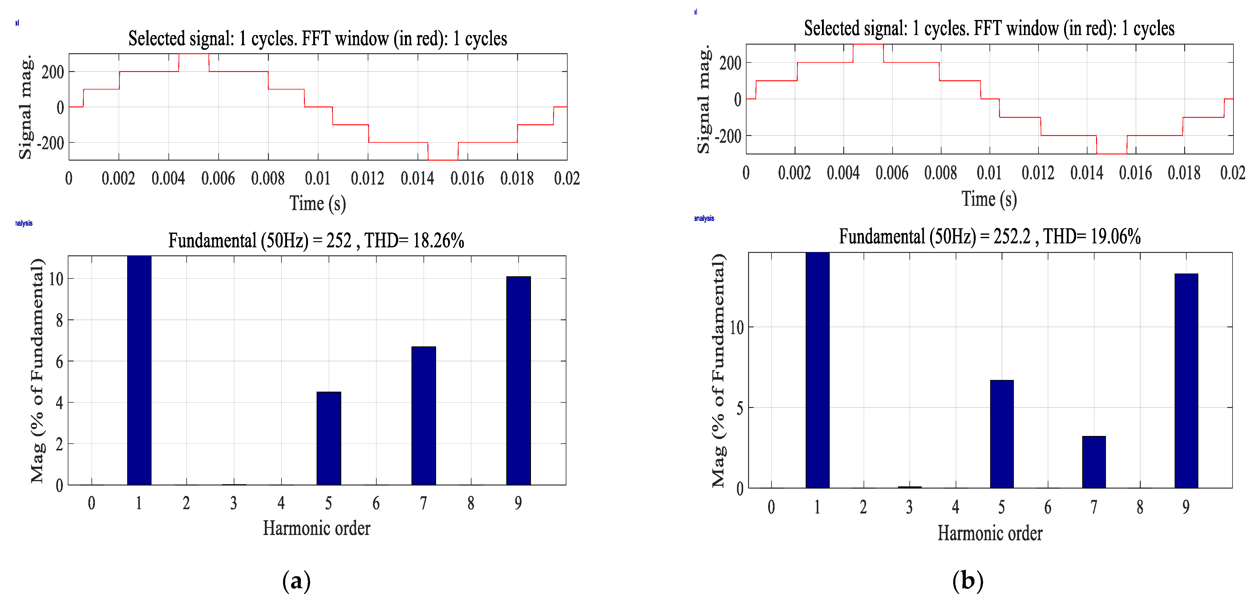
| 2.2599 | 0.05 | 21.81 | 0.03 | 18.26 |
| 2.35 | 0.03 | 22.43 | 0.03 | 18.31 |
| 2.425 | 0.01 | 22.54 | 0.05 | 18.54 |
| Conv. SHE | Prop. SHE | |||
|---|---|---|---|---|
| 9th-Order Harmonic Content Relative to Fundamental (%) | THD (%) | 9th-Order Harmonic Content Relative to Fundamental (%) | THD (%) | |
| 2.297 | 0.08 | 19.67 | 0.06 | 18.42 |
| 2.623 | 0.06 | 21.46 | 0.01 | 18.15 |
| 2.754 | 0.01 | 18.87 | 0.05 | 17.02 |
| 2.8359 | 0.01 | 17.82 | 0.08 | 15.27 |
| 2.90 | 0.01 | 18.07 | 0.03 | 14.64 |
Publisher’s Note: MDPI stays neutral with regard to jurisdictional claims in published maps and institutional affiliations. |
© 2022 by the authors. Licensee MDPI, Basel, Switzerland. This article is an open access article distributed under the terms and conditions of the Creative Commons Attribution (CC BY) license (https://creativecommons.org/licenses/by/4.0/).
Share and Cite
S., G.; Chappa, A.; Rao, K.D.; Dawn, S.; Ustun, T.S. Development of an Enhanced Selective Harmonic Elimination for a Single-Phase Multilevel Inverter with Staircase Modulation. Electronics 2022, 11, 3902. https://doi.org/10.3390/electronics11233902
S. G, Chappa A, Rao KD, Dawn S, Ustun TS. Development of an Enhanced Selective Harmonic Elimination for a Single-Phase Multilevel Inverter with Staircase Modulation. Electronics. 2022; 11(23):3902. https://doi.org/10.3390/electronics11233902
Chicago/Turabian StyleS., Govind, Anilkumar Chappa, K. Dhananjay Rao, Subhojit Dawn, and Taha Selim Ustun. 2022. "Development of an Enhanced Selective Harmonic Elimination for a Single-Phase Multilevel Inverter with Staircase Modulation" Electronics 11, no. 23: 3902. https://doi.org/10.3390/electronics11233902