
Modeling of a Compact Dual Band and Flexible Elliptical-Shape Implantable Antenna in Multi-Layer Tissue Model


1
Telecommunication Engineering Department, Arab American University, Jenin P.O. Box 240, Palestine
2
Electrical Engineering Department, Applied Science Private University, Amman 11931, Jordan
*
Author to whom correspondence should be addressed.
Electronics 2022, 11(20), 3406; https://doi.org/10.3390/electronics11203406
Submission received: 18 September 2022
/
Revised: 16 October 2022
/
Accepted: 19 October 2022
/
Published: 20 October 2022
(This article belongs to the Special Issue Advances and Applications of Microwave Imaging)
Abstract
:A flexible antenna of compact size with a dual band elliptical-shape implantable is designed for biomedical purposes. The suggested antenna has an elliptical shape to be more comfortable for being implanted in human tissue. The implantable antenna is printed on RO3010 substrate with 2 mm as a thickness and 10.2 as a dielectric constant. It consists of an active planar C-shaped element and a parasitic planar inverted C-shaped element. The proposed antenna is designed with a major axis radius of 12 mm and a minor axis radius of 8 mm. It operates in dual bands: The Industrial Scientific and Medical band (ISM) [2.4 GHz–3.5 GHz] and Medical Implant Communications Service band (MICS) [394 MHz–407.61 MHz]. A short-circuited pin is used to minimize the antenna’s overall size and for further size reduction a capacitive load is used between the radiator and the ground plane. For biocompatibility, a thin-thickness layer of Alumina is used as a superstrate. The suggested antenna is tested in a multi-layer tissue model and the Specific Absorption Rate (SAR) value is computed. The proposed antenna was fabricated, and the reflection coefficient is measured and compared with simulated results.
1. Introduction
Implantable antennas are very important in the biomedical and engineering fields. Implantable antennas are employed in many biomedical applications such as temperature monitoring, cancer detection, tumor detection, orthopedic monitoring, glucose monitoring, digestive monitoring, capsule endoscopy, etc. [1,2,3,4,5,6]. In [7,8,9], compact dual and triple frequency bands rectangular-shape implantable antennas were proposed. The compact size was achieved using short-circuited pins, while dual and triple frequency bands were obtained by inserting slots in the radiating patch and in the ground plane. In [9], Defected Ground Structure (DGS) was used for multiple bands antenna. Generally, implantable antennas suffer from low gain and narrow bandwidth. In [10,11,12,13,14,15,16], several techniques were used to improve the gain and bandwidth. In [10], a metamaterial consisting of two split ring resonators was used to reduce the proposed antenna size (29 × 28 mm2) and enhance the gain. The suggested antenna was printed on FR4 substrate and operates at ISM band. A wide frequency bandwidth antenna [1.35–3.5 GHz] was achieved in [11] with metamaterial split ring resonators and ring slots. For biocompatibility with human body tissue, a silicon substrate with relative permittivity 11.7 was used, while the radiator was made of gold. The gain of the proposed antenna in [12] was enhanced by 3 dB using a metamaterial array with high epsilon values. The implantable antenna in [12] was printed on (10 × 10 mm2) Kapton polyimide substrate, Rogers 6010 superstrate and operates at ISM band. In [14], a patch antenna was loaded by a superstrate made of Taconic Cer-10 material for a wide bandwidth and high gain. A frequency selective surface in [15] was placed as a reflector below a 13 × 13 mm2 dual-ring slot antenna to enhance the antenna gain from −10.1 dB to −6.3 dB. For biocompatibility issues, the proposed antenna is printed on a polyimide substrate with dielectric constant 2.91 and loss tangent 0.005.
To achieve biocompatibility with human body tissues, several materials such as Teflon, Alumina, and polyimide are used as a superstrate to cover the antenna [17,18,19,20]. In this work, the main objective is to design a flexible antenna of compact size and with a dual band. To avoid sharp edges in the design and to make the suggested antenna easier to insert into the human body, an elliptical-shape antenna is designed and printed on elliptical RO3010 substrate. The compact size of the antenna is obtained using a short-circuited pin and for additional size reduction, a capacitive load is inserted between the ground plane and the radiator element. For the dual band antenna, a planar C-shaped is used as an active element to operate at the MICS band and a planar inverted C-shaped is used as a parasitic element to work at the ISM band. To ensure biocompatibility, Alumina as a thin layer is employed as a superstrate. The antenna is modeled and simulated in multi-layer tissue model to analyze the effect of mismatch in various tissue environments. The SAR value is also computed to ensure safety. The paper is structured as follows: the characteristics and design of the suggested antenna in a multi-layer human tissue model are given in Section 2. Analysis and discussion of the simulation and measured results are given in Section 3. Finally, summaries of the work are presented in Section 4.
2. Antenna Design Characteristics
The elliptical-shape antenna was realized on a RO3010 substrate with a dielectric constant of 10.2 and a thickness of 2 mm, while the radiator was made of copper. A thin layer of Alumina with a dielectric constant of 9.4 and a thickness of 0.35 mm was used to separate the conducting elements from the human body tissues. The antenna consists of two sections: planar C-shaped as an active element, and planar inverted C-shaped as a parasitic element. The major and minor axes of the ellipse are 12 mm and 8 mm, respectively. The idea behind the elliptical shape of the design is to make the implantable antenna flexible and smoother for the patient by avoiding sharp edges of the conventional rectangular-shape implantable antennas. A short-circuited pin between the active radiator and the ground plane is used for a compact antenna size. A further size reduction was obtained by inserting a capacitive load of 6 pF between the parasitic radiator and the ground plane. The geometry of the suggested antenna is presented in Figure 1. A CST simulator was used for the antenna design and simulation. A three-layer tissue model of size 70 × 60 × 14 mm3 was used. The tissue model consisted of skin, fat, and muscle layers with electrical properties (dielectric constant, , conductivity, σ, loss tangent) for human body tissue layers at MICS and ISM bands according to [21]. The antenna was implanted within the muscle layer at 7 mm from the skin-free space interface, see Figure 2.
3. Results and Discussion
The suggested antenna operates at dual bands: the MICS band [394 MHz–407.61 MHz], and the ISM band [2.4 GHz–3.5 GHz]. The reflection coefficient for the MICS and ISM bands of the suggested antenna when implanted within the muscle layer is given in Figure 3.
The antenna operates at 402.5 MHz with a reflection coefficient of −18.79 dB and a frequency band of 13.61 MHz for the MICS band (at −10 dB) and operates at 2.467 GHz with −50.71 dB as a reflection coefficient and a wide frequency band of 1.1 GHz for the 2212ISM band (at −10 dB). The 2D far fields of the suggested antenna are presented in Figure 4. H-plane at shows an omnidirectional pattern, see Figure 4a. E-plane at phi = 0° also shows an omnidirectional pattern, see Figure 4b. The simulated gain at 402.5 MHz and at 2.467 GHz is found as −30.04 dB and −1.3 dB, respectively.
The simulated SAR values (for 1 watt input power) at 402.5 MHz were found to be 225.17 W/Kg for 1 g of tissue and 46.72 W/Kg for 10 g of tissue. At 2.467 GHz, the SAR values were found to be 130.54 W/Kg for 1 g of tissue and 41.84 W/Kg for 10 g of tissue. For the obtained SAR values to be within the limitations defined by IEEE standards (the optimal SAR value is less than 1.6 W/Kg for the C95.1-1999 system and less than 2 W/kg for C95.1-2005), the input power at 402.5 MHz should not exceed 7.09 mW and 42.7 mW for 1 g and 10 g of tissue, respectively.
At 2.467 GHz, the input power should not exceed 12.25 mW and 47.7 mW for 1 g and 10 g of tissue respectively, see Table 1.
Simulated SAR values for 10 g of tissue at 402.5 MHz and 2.467 GHz are illustrated in Figure 5a,b, respectively.
The proposed antenna in Figure 1 was fabricated on RO3010 substrate as shown in Figure 6. A capacitive load of 10.709 pF was used instead of 6 pF (this capacitance value is available in our lab). The measured and simulated reflection coefficients are in good agreement, as presented in Figure 7.
To study the effect of mismatch in various tissue conditions, the proposed antenna was placed inside the skin layer. To solve the mismatch due to different layer environments, the feed point position was optimized, and the width of the planar C-shaped active element and planar inverted C-shaped parasitic element was now 2 mm instead of 2.5 mm compared to the case of the suggested antenna placed within the muscle layer. In addition, the superstrate thickness was 0.15 mm and the skin thickness was optimized to be 6.47 mm. The capacitive load was now 10 pF. A reflection coefficient of −21.84 dB and −32.56 dB were the results at the MICS and ISM bands, respectively (see Figure 8a,b, respectively).
The simulated SAR values (for 1 watt input power) at 402.5 MHz were found to be 523.67 W/Kg for 1 g of tissue and 112.71 W/Kg for 10 g of tissue. At 2.467 GHz, the SAR values were 183.242 W/Kg for 1 g of tissue and 75.12 W/Kg for 10 g of tissue. For the obtained SAR values to be within the limitations defined by IEEE standards, the input power at 402.5 MHz should not exceed 3.05 mW and 17.7 mW for 1 g and 10 g of tissue, respectively. At 2.467 GHz, the input power should not exceed 8.72 mW and 26.5 mW for 1 g and 10 g of tissue, respectively. Simulated SAR values for 10 g of tissue at 402.5 MHz and 2.467 GHz are illustrated in Figure 9a,b, respectively.
The suggested antenna was implanted within the fat layer. To solve the mismatch due to different layer environments, the locations of the feed point and short-circuited pin were optimized. The major and minor axes of the ellipse were increased to 15 mm and 11 mm, respectively. The width of the planar C-shaped active element and planar inverted C-shaped parasitic element was now 2.5 mm, the same as the case of the suggested antenna implanted within the muscle layer. In addition, the superstrate thickness was 0.2 mm, and the skin thickness was optimized to be 4 mm. The capacitive load was 8 pF. A reflection coefficient of −23.15 dB and −22.38 dB were the results at the MICS and ISM bands, respectively (see Figure 10a,b, respectively).
The computed SAR values (for 1 watt input power) at 402.5 MHz were 316.87 W/kg for 1 g of tissue and 81.94 W/Kg for 10 g of tissue. At 2.45 GHz, the SAR values were 81.23 W/kg for 1 g of tissue and 35.7 W/kg for 10 g of tissue. For the obtained SAR values to be within the limitations defined by IEEE standards, the input power at 402.5 MHz should not exceed 5.04 mW and 23.4 mW for 1 g and 10 g of tissue, respectively.
At 2.45 GHz, the input power should not exceed 19.67 mW and 56 mW for 1 g and 10 g of tissue, respectively. Simulated SAR values for 10 g of tissue at 402.5 MHz and 2.45 GHz are illustrated in Figure 11a,b, respectively.
The reflection coefficient of the proposed antenna for both cases, implanted in the skin layer and implanted in the fat layer, is presented in Figure 12. The implanted antenna in the skin layer was matched over a wider frequency bandwidth at MICS, while a wider frequency bandwidth was obtained in the fat layer at ISM. Gain enhancement was obtained in the fat layer for both MICS and ISM bands compared to the skin layer. A comparison between the obtained results of the suggested antenna being inserted in the skin, fat, and muscle layers is presented in Table 2. Enhanced gain values were obtained as the proposed antenna was inserted in the fat layer compared to the skin layer, but on the other hand, a larger antenna size was then obtained. At the MICS band, the widest bandwidth was obtained when the suggested antenna was inserted in the skin layer, while the widest bandwidth at ISM band was obtained as the antenna was inserted in the muscle layer. The highest SAR values were obtained when the suggested antenna was inserted in the skin layer. A comparison of the main parameters between this work and previous works is presented in Table 3.
4. Conclusions
In this study, a compact size flexible and dual band elliptical-shaped implantable antenna with a smooth geometry was modeled and analyzed. The suggested antenna works at the MICS band with a reflection coefficient of −18.78 dB at 402.5 MHz, and at the ISM band with a reflection coefficient of −50.71 dB at 2.467 GHz. A wide bandwidth of 1100 MHz was obtained at the ISM band. The suggested antenna simulated gain values of −30.04 dB and −1.3 dB at 402.5 MHz and 2.467 GHz, respectively. The SAR value was conducted, and the input power was optimized to meet the IEEE standard limitations. The efficiency of the proposed antenna was analyzed and compared in the skin, fat, and muscle layers. A compact size dual band and flexible geometry make the suggested antenna a good candidate for biomedical purposes.
Author Contributions
Formal analysis, S.S.; Methodology, S.S.; Software, D.Z.; Writing—review & editing, S.S. and A.A. All authors have read and agreed to the published version of the manuscript.
Funding
This research received no external funding.
Conflicts of Interest
The authors declare no conflict of interest.
References
- Malika, T.; Abdennaceur, K.; Rahma, A.; Frédéric, A. Miniaturized on-body patch antenna for 430MHz wireless digestive monitoring system. In Proceedings of the 2014 IEEE Workshop on Biometric Measurements and Systems for Security and Medical Applications (BIOMS), Rome, Italy, 17 October 2014; pp. 57–60. [Google Scholar] [CrossRef]
- Scanlon, W.G.; Evans, N.E.; McCreesh, Z.M. RF performance of a 418- MHz radio telemeter packaged for human vaginal placement. IEEE Trans. Biomed. Eng. 1997, 44, 427–430. [Google Scholar] [CrossRef] [PubMed]
- Khokle, R.P.; Esselle, K.P.; Heimlich, M.; Bokor, D. Design of a miniaturized bone implantable antenna for a wireless implant monitoring device. In Proceedings of the Loughborough Antennas & Propagation Conference (LAPC), Loughborough, UK, 13–14 November 2017; pp. 1–2. [Google Scholar] [CrossRef]
- Karacolak, T.; Hood, A.Z.; Topsakal, E. Design of a dual-band implantable antenna and development of skin mimicking gels for continuous glucose monitoring. IEEE Trans. Microw. Theory Tech. 2008, 56, 1001–1008. [Google Scholar] [CrossRef]
- Lee, S.H.; Lee, J.; Yoon, Y.; Park, S.; Cheon, C.; Kim, K.; Nam, S. A wideband spiral antenna for ingestible capsule endoscope systems: Experimental results in a human phantom and a pig. IEEE Trans. Biomed. Eng. 2011, 58, 1734–1741. [Google Scholar] [PubMed]
- Salama, S.; Zyoud, D.; Daghlas, R.; Abuelhaija, A. Design of a Planar Inverted F-Antenna for Medical Implant Communications Services Band. In Journal of Physics: Conference Series; IOP Publishing: Bristol, UK, 2020; Volume 1711. [Google Scholar]
- Salama, S.; Zyoud, D.; Abuelhaija, A. Design of a Dual-Band Planar Inverted F-L Implantable Antenna for Biomedical Applications. In Journal of Physics: Conference Series; IOP Publishing: Bristol, UK, 2020; Volume 1711. [Google Scholar]
- Hossain, S.; Nahar Jui, N.; Hossain, F.; Morshed, K.M. A Simple Triple-band Antenna for Implantable Biomedical Application. In Proceedings of the IEEE Region 10 Humanitarian Technology Conference (R10-HTC), Dhaka, Bangladesh, 21–23 December 2017. [Google Scholar]
- Mainul, E.A.; Hossain, F. A Miniaturized Triple Band DGS Implantable Antenna for Biotelemetry. In Proceedings of the 2021 International Conference on Electrical, Communication, and Computer Engineering (ICECCE), Kuala Lumpur, Malaysia, 12–13 June 2021. [Google Scholar]
- Goswami, S.; Karia, D.C. A metamaterial-inspired circularly polarized antenna for implantable applications. Eng. Rep. 2020, 2, e12251. [Google Scholar] [CrossRef]
- Bhattacharjee, S.; Maity, S.; Chaudhuri, S.R.; Mitra, M. Metamaterial-inspired wideband biocompatible antenna for implantable applications. IET Microw. Antennas Propag. 2018, 12, 1799–1805. [Google Scholar] [CrossRef]
- Das, S.; Mitra, D. A Compact Wideband Flexible Implantable Slot Antenna Design with Enhanced Gain. IEEE Trans. Antennas Propag. 2018, 66, 4309–4314. [Google Scholar] [CrossRef]
- Lovat, G.; Burghignoli, P.; Capolino, F.; Jackson, D.R. Combinations of Low/High Permittivity and/or Permeability Substrates for Highly Directive Planar Metamaterial Antennas. IET Microw. Antennas Propag. 2007, 1, 177–183. [Google Scholar] [CrossRef] [Green Version]
- Ta, S.X.; Nguyen, T.K. AR Bandwidth and Gain Enhancements of Patch Antenna Using Single Dielectric Superstrate. Electron. Lett. 2017, 53, 1015–1017. [Google Scholar] [CrossRef]
- Das, S.; Mitra, D.; Mandal, B.; Augustine, R. Implantable antenna gain enhancement using liquid metal-based reflector. Appl. Phys. A Mater. Sci. Processing 2020, 126, 1–7. [Google Scholar] [CrossRef]
- Xu, L.; Jin, X.; Hua, D.; Lu, W.J.; Duan, Z. Realization of Circular Polarization and Gain Enhancement for Implantable Antenna. IEEE Access 2020, 8, 16857–16864. [Google Scholar] [CrossRef]
- Soontornpipit, P.; Furse, C.M.; Chung, Y.C. Design of implantable microstrip antennas for communication with medical implants. IEEE Trans. Microw. Theory Tech. 2004, 52, 1944–1951. [Google Scholar] [CrossRef]
- Wong, K.L. Compact and Broadband Microstrip Antennas, 1st ed.; Wiley: New York, NY, USA, 2002. [Google Scholar]
- Gozasht, F.; Mohan, A.S. Miniaturized slot PIFA antenna for triple band implantable biomedical applications. In Proceedings of the IEEE MTT-S International Microwave Workshop Series on RF and Wireless Technologies for Biomedical and Healthcare Applications (IMWS-BIO), Singapore, 9–11 December 2013. [Google Scholar]
- Constantin, C.P.; Afori, M.; Damian, R.F.; Rusu, R.D. Biocompatibility of Polyimides: A Mini-Review. Materials 2019, 12, 3166. [Google Scholar] [CrossRef] [PubMed] [Green Version]
- Basir, A.; Bouazizi, A.; Zada, M.; Iqbal, A.; Ullah, S.; Naeem, U. A Dual-Band Implantable Antenna with Wide-Band Characteristics at MICS and ISM Bands. Microw. Opt. Technol. Lett. 2018, 60, 2944–2949. [Google Scholar] [CrossRef]
Figure 1.
Structure of the suggested antenna, top and side view.
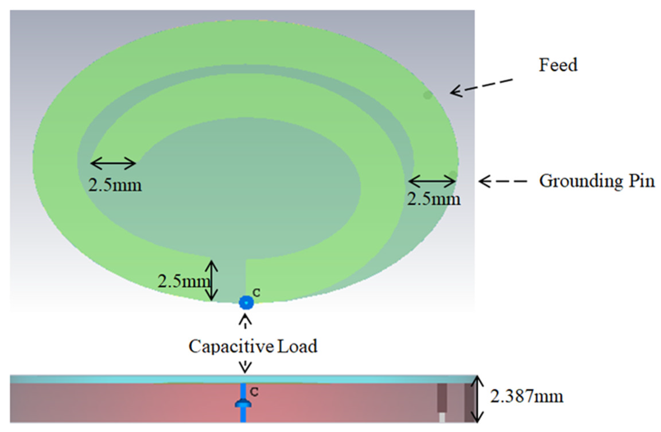
Figure 2.
Average thicknesses of the three-layered tissue model.
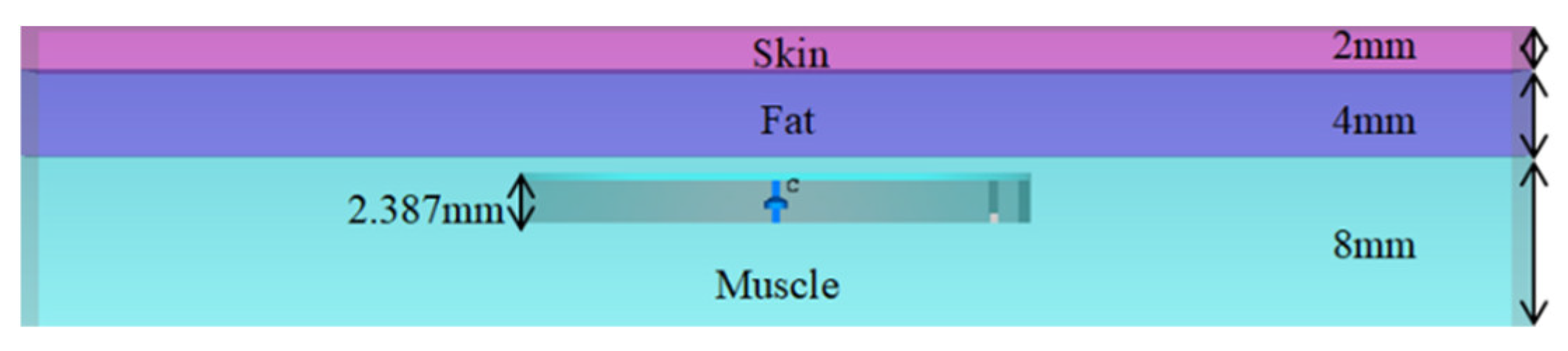
Figure 3.
Simulation reflection coefficient of the suggested antenna.
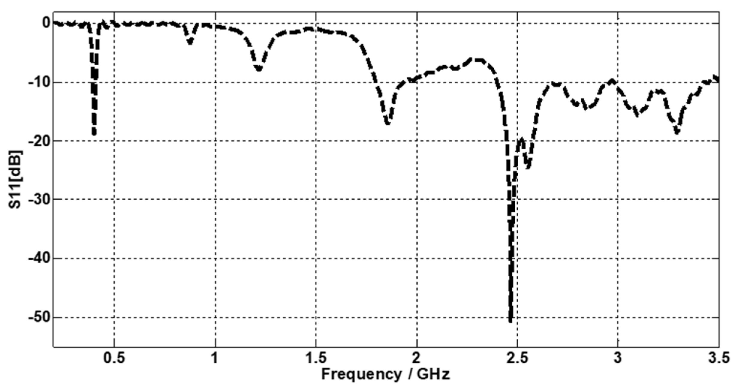
Figure 4.
Simulation 2D far fields of the suggested antenna: (a) H-plane, and (b) E-plane. At 402 MHz (dash line), and at 2.467 GHz (solid line).
Figure 4.
Simulation 2D far fields of the suggested antenna: (a) H-plane, and (b) E-plane. At 402 MHz (dash line), and at 2.467 GHz (solid line).

Figure 5.
Simulated SAR values for 10 g of tissue at (a) 402.5 MHz and (b) 2.467 GHz.
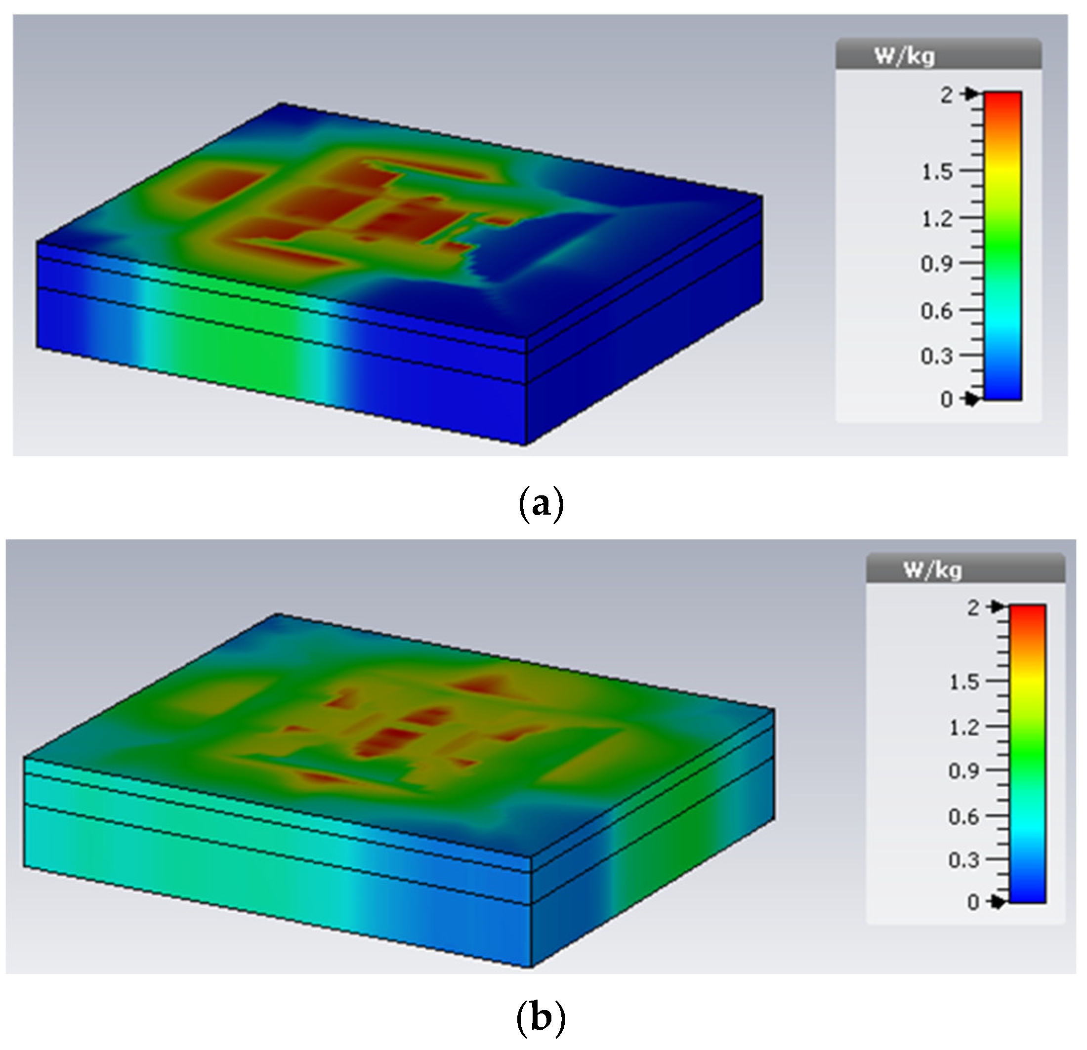
Figure 6.
The fabricated prototype of the proposed antenna.
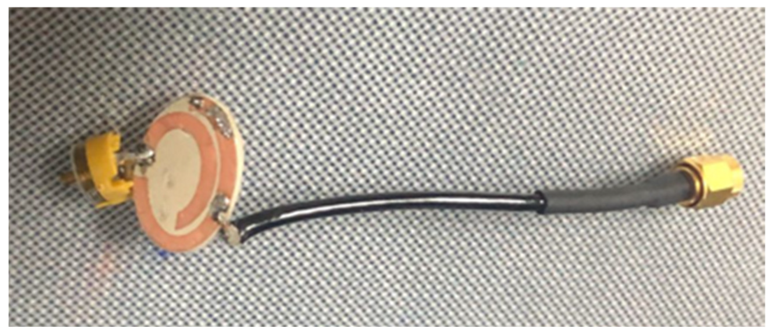
Figure 7.
Simulation (solid line) and measured (dash line) reflection coefficient of the proposed antenna.
Figure 7.
Simulation (solid line) and measured (dash line) reflection coefficient of the proposed antenna.

Figure 8.
Simulation reflection coefficient of the proposed antenna (placed inside the skin layer) at (a) 402.5 MHz, and (b) 2.467 GHz.
Figure 8.
Simulation reflection coefficient of the proposed antenna (placed inside the skin layer) at (a) 402.5 MHz, and (b) 2.467 GHz.

Figure 9.
SAR values for 10 g of tissue at (a) 402.5 MHz and (b) 2.467 GHz. (The proposed antenna placed inside the skin layer).
Figure 9.
SAR values for 10 g of tissue at (a) 402.5 MHz and (b) 2.467 GHz. (The proposed antenna placed inside the skin layer).
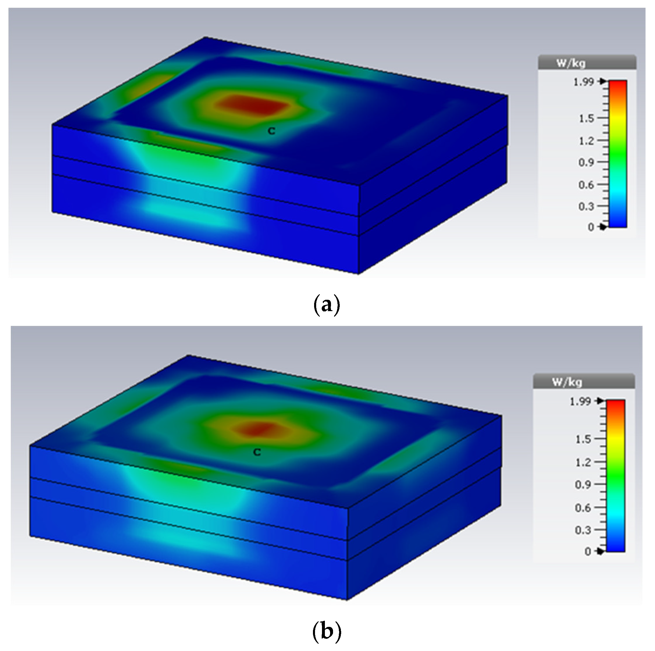
Figure 10.
Simulation reflection coefficient of the suggested antenna (placed inside the fat layer) at (a) 402.5 MHz, and (b) 2.45 GHz.
Figure 10.
Simulation reflection coefficient of the suggested antenna (placed inside the fat layer) at (a) 402.5 MHz, and (b) 2.45 GHz.

Figure 11.
Simulated SAR values for 10 g of tissue at (a) 402.5 MHz and (b) 2.45 GHz. (The proposed antenna placed inside the fat layer).
Figure 11.
Simulated SAR values for 10 g of tissue at (a) 402.5 MHz and (b) 2.45 GHz. (The proposed antenna placed inside the fat layer).
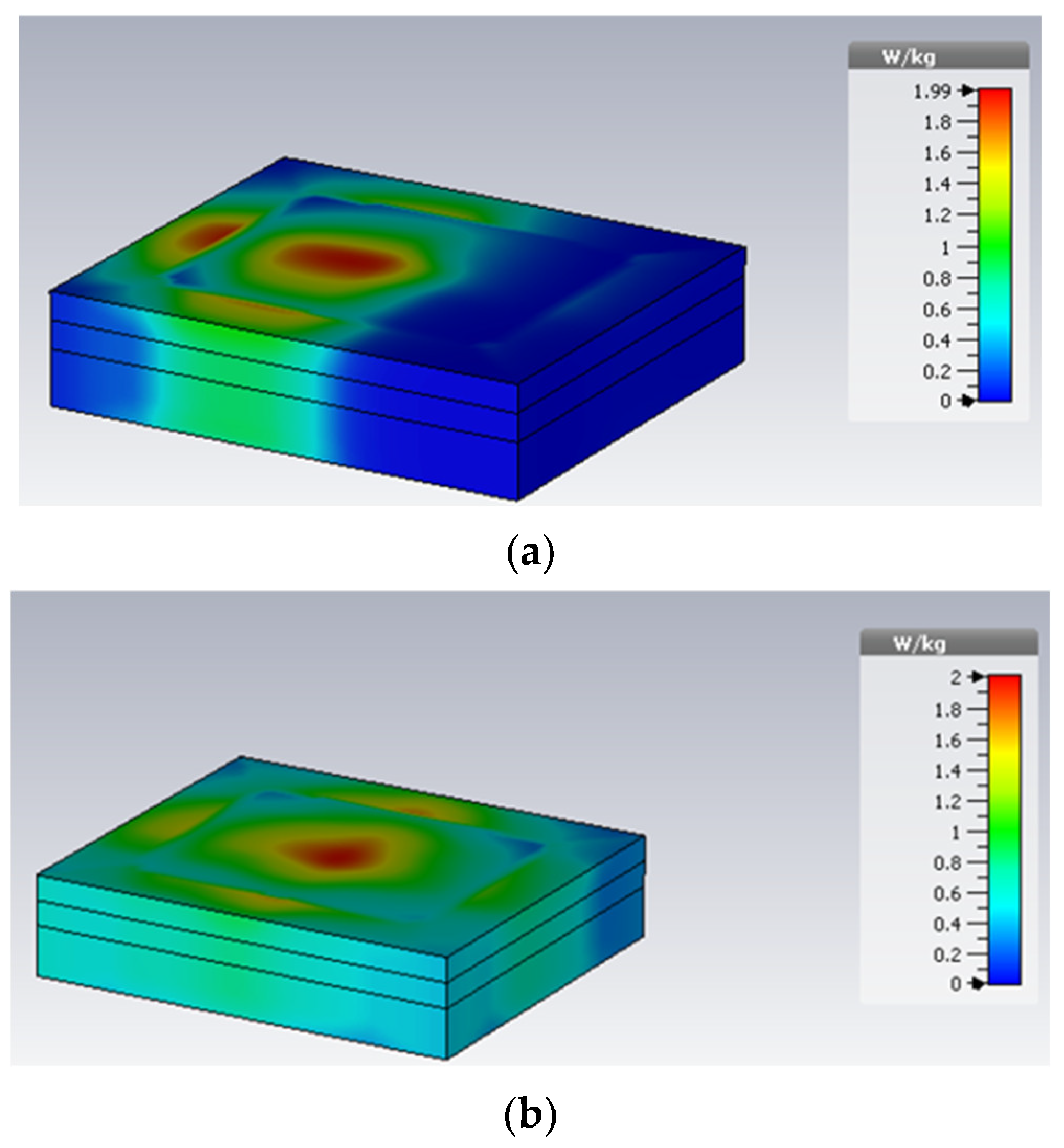
Figure 12.
Simulation reflection coefficient of the suggested antenna placed inside the skin layer (solid line) and the fat layer (dash line) at (a) MICS band, and (b) ISM band.
Figure 12.
Simulation reflection coefficient of the suggested antenna placed inside the skin layer (solid line) and the fat layer (dash line) at (a) MICS band, and (b) ISM band.


Table 1.
Simulated SAR values for 1 watt input power and the calculated maximum input power for the 1 g and 10 g models.
Table 1.
Simulated SAR values for 1 watt input power and the calculated maximum input power for the 1 g and 10 g models.
| Simulated SAR Values | SAR (1 g Model) | SAR (10 g Model) | ||
|---|---|---|---|---|
| MICS | ISM | MICS | ISM | |
| 189.42 W/kg | 124.246 W/kg | 42.0014 W/kg | 41.7769 W/kg | |
| SAR limits | 1.6 W/Kg C95.1-1999 | 2 W/Kg C95.1-2005 | ||
| Calculated maximum input power | 8.43 mW | 12.85 mW | 47.5 mW | 47.8 mW |
Table 2.
Reflection coefficient, frequency band, and gain of the proposed antenna placed in different tissue environments.
Table 2.
Reflection coefficient, frequency band, and gain of the proposed antenna placed in different tissue environments.
| Three Layer Tissue Model | Reflection Coefficient (dB) | Bandwidth (MHz) | Gain (dB) | |||
|---|---|---|---|---|---|---|
| MICS | ISM | MICS | ISM | MICS | ISM | |
| Skin Layer | −21.84 dB | −32.56 dB | 67.77 | 109.2 | −36.24 dB | −7.74 dB |
| Fat Layer | −23.15 dB | −22.38 dB | 22.51 | 591.7 | −29.57 dB | −3.83 dB |
| Muscle Layer | −18.79 dB | −50.71 dB | 13.61 | 1100 | −30.04 dB | −1.3 dB |
Table 3.
A comparison of the main parameters between this work and previous works.
| Ref. | Substrate | Frequency Bands | Antenna Size (mm2) | Gain (dB) |
|---|---|---|---|---|
| [6] | RO3010 | MICS | (32 × 24) | −18 |
| [7] | RO3010 | MICS, ISM | (27 × 19) | −30.14, 2.45 |
| [10] | FR4 | ISM | (29 × 28) | 4.86 |
| [12] | Kapton polyimide | ISM | (10 × 10) | −9 |
| [15] | polyimide | ISM | (13 × 13) | −6.3 |
| This work | RO3010 | MICS, ISM | (12 × 8) | −30.04, −1.3 |
Publisher’s Note: MDPI stays neutral with regard to jurisdictional claims in published maps and institutional affiliations. |
© 2022 by the authors. Licensee MDPI, Basel, Switzerland. This article is an open access article distributed under the terms and conditions of the Creative Commons Attribution (CC BY) license (https://creativecommons.org/licenses/by/4.0/).
Share and Cite
MDPI and ACS Style
Salama, S.; Zyoud, D.; Abuelhaija, A. Modeling of a Compact Dual Band and Flexible Elliptical-Shape Implantable Antenna in Multi-Layer Tissue Model. Electronics 2022, 11, 3406. https://doi.org/10.3390/electronics11203406
AMA Style
Salama S, Zyoud D, Abuelhaija A. Modeling of a Compact Dual Band and Flexible Elliptical-Shape Implantable Antenna in Multi-Layer Tissue Model. Electronics. 2022; 11(20):3406. https://doi.org/10.3390/electronics11203406
Chicago/Turabian StyleSalama, Sanaa, Duaa Zyoud, and Ashraf Abuelhaija. 2022. "Modeling of a Compact Dual Band and Flexible Elliptical-Shape Implantable Antenna in Multi-Layer Tissue Model" Electronics 11, no. 20: 3406. https://doi.org/10.3390/electronics11203406
Note that from the first issue of 2016, this journal uses article numbers instead of page numbers. See further details here.