
Design and Analysis of Omnidirectional Receiver with Multi-Coil for Wireless Power Transmission

1
Institute of Microelectronics of the Chinese Academy of Sciences, Beijing 100029, China
2
Department of Microelectronic, University of Science and Technology of China, Hefei 230026, China
*
Authors to whom correspondence should be addressed.
Electronics 2022, 11(19), 3103; https://doi.org/10.3390/electronics11193103
Submission received: 5 September 2022
/
Revised: 20 September 2022
/
Accepted: 22 September 2022
/
Published: 28 September 2022
(This article belongs to the Special Issue Advanced Technologies and Applications in Wireless Power Transfer Systems)
Abstract
:In order to solve the misalignment problem of wireless power transmission, this paper designed and analyzed the omnidirectional receiver with multi-coil. The circuit models and transmission characteristics of the wireless power transfer system (WPTS) containing multi-coil were established. Besides, an accurate mutual inductance modelling method of the circular coil under different horizontal offset and angular deflection was presented. Based on the circuit models and the mutual inductance model, the relationship between transmission characteristics and the coil parameters were studied. Simultaneously, the design method which can synthetically and quantificationally consider the radius of the coil and the number of turns was proposed. Finally, an omnidirectional receiver with multi-coil using the quantificational model and transmission characteristics in different horizontal offset and angular deflection was designed.The transmission efficiency of three-coils-receiver system was up 12.3% higher than that of one-coil-receiver system and 4% higher than that of two-coils-receiver system when horizontal offset was between 0 cm and 30 cm. Similarly, when angular deflection was between 0 and , the efficiency of three-coils-receiver system was up 73.25% higher than that of one-coil-receiver system and 1.6% higher than that of two-coils-receiver system.
1. Introduction
Since Massachusetts Institute of Technology proposed magnetic coupling resonance wireless power transmission technology, the related technologies has attracted more and more attention from research institutions and scholars [1,2,3]. Compared with the magnetic induction mode, the magnetic coupling resonance can obtain greater transmission distance [4,5,6]. With the development of mobile phones, electric vehicles and the space stations, the magnetic coupling resonance wireless power transmission technology will have a wider and wider application space [7,8,9]. It will develop rapidly because of its potential in application such as consume electronic products, robotics, electric vehicles, aviation and medical devices [10,11].
However, there are still a lot of problems need to be solved. The quantificational design of coil resonator is a hard problem for wireless power transfer systems [12,13]. A good resonator design is of great significance to improve the effectiveness and stability of the system. In ref. [14] proposed a differential evolution algorithm to determine the capacitance values of resonator and improve the performance of WPTS. The maximum power transfer efficiency was 88% [14]. Afterwards, Tuba Yilmaz described the adoption of multi-objective hybrid particle swarm optimization and multi-objective real numbered particle swarm optimization algorithms for a circular coupler design to identify a minimum set of key optimization parameter [15]. But there is little discussion about the quantification design of coil.
In addition, in many application scenarios, such as wireless transmission in outer space and power online monitoring equipment wireless power supply, the misalignment problem is another inevitable challenge for WPTS. The efficient omnidirectional receiver is a economic and attractive strategy for misalignment WPTS. For the traditional WPTS with one transmitting and one receiving coil, it is difficult to achieve high efficiency power transmission when the receiving load appears large angle deflection. At present, the main solution is to use multiple transmitting coils or multiple receiving coils. In refs. [16,17] designed omnidirectional WPTS using three-orthogonal-transmitting-coil topology. However, the modulation method of multiple transmitting coils topology is complex, which limited its application [16,17]. In ref. [18] proposed crossed dipole coils for the wide-range 3-D omnidirectional inductive power transfer, and 3-D omnidirectional WPTS was realized. The maximum overall efficiency was 33.6% when the input power was 100 W [18]. In ref. [19] presented series-parallel topology of magnetic coupling system whose efficiency was 17%, when the deflection angle was [19]. In ref. [20] introduced free positioning WPTS with optimum switching phase detection technique, and the efficiency of system was 56% when the deflection angle was , the efficiency was 36% when the deflection angle was [20]. In the same year, M.Talaat analysed a model with different coil geometries and coil arranging positions. When inclining the secondary coil with an angle , the magnetic flux of the inclined side decreases to 22.2% of the aligned side [21]. Huilin An designed omnidirectional receiver with two coils, the anti-deflection and anti-offset properties of which were better than that of receiver with one coil. When the deflection angle is , the efficiency of system was 90%. But load the power and effectively curve are not smooth and steady enough, and the efficiency is not ideal for the receiver with two coils [22].
Furthermore, the accurate mutual inductance model, which is very important for quantificational design and misalignment problem, has attracted enormous interest from the scientist. In refs. [23,24,25] presented mutual inductance models, including the circular coil and square coil in different horizontal offset and angular deflection, but the cross section of coil was not considered in these papers, which will led to an inaccurate results [23,24,25]. Slobodan dealt with novel formulas for calculating the mutual inductance and the magnetic force between two coaxial coils, which are made up of a circular coil of the rectangular cross section and a thin disk coil [26]. Unfortunately, this paper ignored the sectional radius of the coil conductor, which is an important factor affecting the inductance, when calculating the inductance formula.
In order to solve the above problems, this paper presents an accurate mutual inductance modeling method of circular coil under different horizontal offset and angular deflection. In this model, the number of turns, the sectional radius of the coil conductor and the spaces between turns of coil are considered. Moreover, a new coil design method, which can quantificationally design the radius and turn number of the coil for the magnetic coupling resonance WPTS, is proposed. Further, based on ref. [22], the omnidirectional receiver, which is consisted of there coils, is designed and manufactured to prove the the correctness and validity modeling approach. This study solve the problems of the misalignment between the transmitter and receiver coil for the WPTS and improve the ability of system against distance offset and angle deflection.
2. Theoretical Analysis of Circuit and Mutual Inductance Models
Accurate circuit model and mutual inductance model are beneficial to analyse the transmission characteristics of the WPTS. Reasonable derivation of transmission characteristics can help us to design coil parameters quickly and accurately. This section will establish the circuit model of WPTS with multi-coil-receiver and analyse the transmission characteristics of that. In addition, the mutual inductance of perfectly aligned and misaligned coils will be derived.
2.1. Circuit Models of Wireless Power Transfer System
In order to overcome the weak anti-offset and anti-angle deflection capabilities of traditional receivers, this paper presents a robust design to realise the stability of performance index over wide deflection angles and long offset distance. The diagrammatic sketch of the proposed structure is shown in Figure 1. The system consists of two parts: transmitting coil and receiving coil. Coil S is transmitting coil and Coil 1, Coil 2, and Coil 3 form the receiving coil. The included angle between any two of coil 1, coil 2, and coil 3 is . The center of transmitting coil and receiving coil are O and O′ respectively, and the corresponding coordinate systems are x-y-z and x′-y′-z′. The included angle between z-axis and z′-axis is . The included angle between x-axis and x′-axis is 0. O″ is the projection of O′ on the x-y coordinate planes. is the vertical distance from the top layer of coil S to the bottom layer of coil 1.
Figure 2 shows the circuit model of proposed WPTS. The , , , , , and are the mutual inductance between coils. , , , are the resistance, resonant capacitor, self-inductance and load resistance of the coil. For example, represents the self-inductance of coil 3.
When the system works at the resonant frequency f, the self-impedance of coil can be calculated by the following formula
where .
, , , , and are mutual impedance between coils, which can be represented as
According to the theory of mutual inductance and Kirchhoff’s law, the loop voltage equation are as follows [13]
, , , and are the current of coil S, coil 1, coil 2 and coil 3, respectively. Using the Formulas (10), (11), and (13), the loop current of transmitting and receiving coil , , , and can be derived as
When and f are constant, combining the Formulas (1), (2), and (4), the relationship between the transmission characteristics of three-coils-receiver system and the parameters of the coil can be obtained. Obviously, this conclusion is also applicable to one-coil-receiver system and two-coils-receiver system.
2.2. Mutaual Inductance of Coupled Coils
An accurate mutual inductance model play an essential role in the research of transmission characteristics. Unfortunately, in the proposed mutual inductance model, the effects of radius and number of turns are rarely involved. In this section, interface radius and spaces between turns are innovatively taken into account in the mutual inductance model [27].
2.2.1. Mutual Inductance of Perfectly Aligned Coils
One loop model of perfectly aligned coils is shown in Figure 3. The point P is on the turn, and the point Q is on the turn. Q′ is the projection of Q on the x-y plane. is the center-to-center distance between coil S and coil 1, which is equal to the distance from Q to Q′. l is the distance from P to Q′, which is expressed as [27]
The magnitude is represented as [27]
The mutual inductance between the ith turn of coil S and the jth turn of coil 1 can be obtained
The perfectly aligned coils is shows in Figure 4a. Coil S and coil 1 are in a coaxial horizontal state. The radius of the coil S and coil 1 are and respectively. P is arbitrary point of coil S, and Q is arbitrary point of coil 1. The magnitude of the of the vector joining point P and point Q is named . The number of turns of coil S are i, i = 1, 2, 3…. The number of turns of coil 1 are j, j = 1, 2, 3…. is the ith turn of coil S, is the jth turn of coil 1.
The cross section diagram of Figure 4a, which is obtained along the y-z plane, is shown in Figure 4b. The interface diameter of the coil S and coil 1 are and respectively. The spaces between turns of the coil S and coil 1 are and respectively. means the center-to-center distance for the top and bottom layer of coil S and coil 1. represents
Applying Formulas (6)–(8) and the dot product of the and , (7) can be written as [27]
where the parameters is [27]
For coil S containing Ns turns and coil 1 containing N1 turns, the total mutual inductance is then [27]
2.2.2. Mutual Inductance of Horizontal Offset and Angular Deflection Coils
Figure 5 shows the configuration between coil S and coil 1 in the case of horizontal offset and angular deflection. The axis of coil S and coil 1 are x-y-z and x′-y′-z′ respectively. O‴ is the projection of O′ on the x-y coordinate planes. O‴ is the projection of O″ on the y axis. is the horizontal offset distance of coil 1 from the axis of coil S, which is equal to the distance from O to O″. O′z″ is the projection of z-axis on the x-z coordinate planes. The included angle between O′z″ and z′-axis and the included angle between O′z″ and z-axis are represented by and . By roll and pitch rotations, which are represented by and in Figure 5, angular deflection can be achieved. The magnitude is calculated by [27]
Combining the Formulas (8), (9), (12) and the dot product of the and , (8) can be written as [27]
where the parameters ,,,, and are [27]
For coil S containing Ns turns and coil 1 containing N1 turns, the total mutual inductance is then [27]
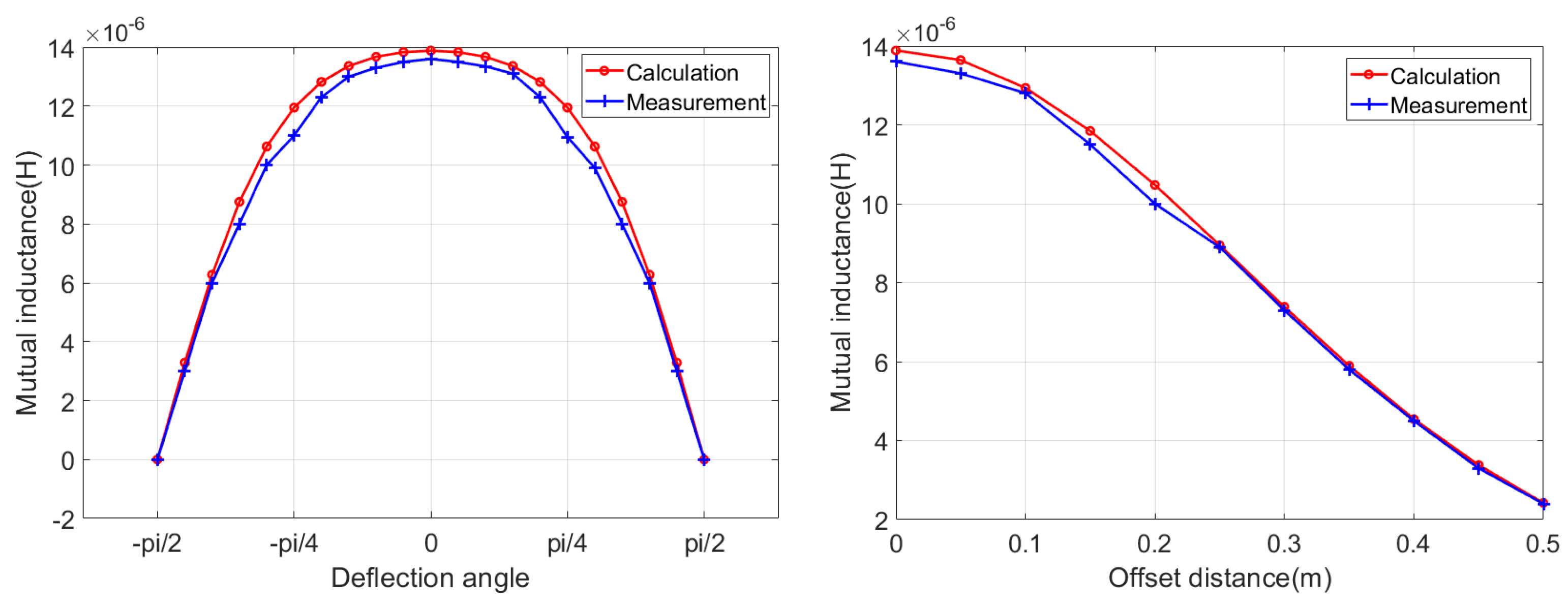
The model accuracy should be presented to confirm validity of the proposed model. For this, this paper compares the calculation results of the model with the measurement, which is shown Figure 6. It can be seen that the calculations of mutual inductance are close to the measurement results, when the deflection angle changes from to , or the offset distance changes from 0 to 0.5 m. The correctness of the calculation method of mutual inductance is verified in this paper.
Figure 5.
Horizontal offset and angular deflection coils.
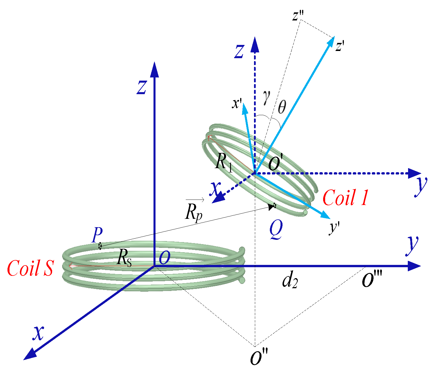
Figure 6.
The verification of mutual inductance formula.The coil parameters are the same in calculation and measurement.
Figure 6.
The verification of mutual inductance formula.The coil parameters are the same in calculation and measurement.
Thus, by applying the Formulas (5)–(19), a clear representation of the relationship between mutual inductance and coil parameters was received. Further, combined with the discussion in Section 2.1 summary, this paper accurately establishes the mapping relationship between coil parameters and transmission performance. This mapping relationship is valid for one-coil receiver systems, two-coil receiver system, and three-coil-receiver systems.
3. Duantificationally Design of Coil Parameters
Coil parameters determine the transmission characteristics of the WPTS. Reasonable coil parameters can improve the efficiency and stability of the system. This section will propose a new coil design method and quantificationally design the coil parameters of multi-coils-receiver system.
For the three-coils-receiver system designed by this paper, the radius of the coil S, coil 1, coil 2 and coil 3 are , , , and respectively. The number of turns of coil S, coil 1, coil 2, and coil 3 are , , , and respectively. The interface diameter of the coil S, coil 1, coil 2, and coil 3 are , , , and respectively. The spaces between turns of the coil S, coil 1, coil 2, and coil 3 are , , , and respectively. The included angle between any two of coil 1, coil 2 and coil 3 are , so the mutual inductance , , and are greater than zero. When considering the mutual inductance of four coils, it is a complicated process to quantificationally design the coil parameters. Among the above coil parameters, the coil diameter and coil turns have the greatest influence on the transmission performance of the WPTS. Therefore, for the convenience of design, this paper first sets other parameters as fixed values, and then analyzes the influence of variable coil diameter and coil turns on the transmission characteristics of WPTS. The performance index used in this paper should satisfy both of the following two conditions: the transmission power of the system is higher than 50 W; the transmission efficiency is above 90% under the condition of 25 V supply voltage and 15 cm transmission distance. Set the parameters of coil 1, coil 2, and coil 3 to consistent, = = = = R, = = = = N, = = = = W = 2 mm, = = = = S = 0.2 mm, = 25 V, = = = = 403 , f = 1 MHz. Based on the above data, this paper carries out numerical analysis on the transmission characteristics of WPTS by MATLAB. Firstly, mutual inductance the , , , , , and are solved by Formulas (13) and (19). Secondly, the impedance , , , , and can be obtained by substituting mutual inductance into Formula (2). Finally, Formulas (1) and (2) are brought into Equation (4), and the numerical analysis of Equation (4) is performed. Therefore, the current in each coil can be determined. Further, we can construct the relationship between the transmission characteristics of WPTS and the coil parameters.
It can be seen from the Figure 7a,b that load power increases firstly and then decreases with the increase of coil diameter and number of turns, however transmission efficiency always increases. The Figure 7c is the sectional view of Figure 7a where the power is equal to 50 W. The curve power equal to 50 W divides the Figure 7a into two regions. In the A region, the load power is greater than 50 W, and in other regions, the power is less than 50 W. The Figure 7d is the sectional view of Figure 7b where the transmission efficiency is equal to 90%. On the curve, the efficiency is equal to 90%. In the B region, the efficiency is greater than 90%, the other regions, the efficiency less than 90%. Therefore, when the intersection parameters of region A and region B are chosen, the expected objectives of this paper can be achieved. Finally, taking into account that the coil diameter should not be too large, and the height should not be too high, the values of coil diameter and number of turns are set to 0.2 m and 11 respectively, in this paper. The detailed coil parameters are tabulated in Table 1. It should be noted that the proposed approach in this paper is general and can be applied to other constraints and other coil numbers.
4. Simulation Analysis and Experimental Verification
In order to verify the correctness of the theoretical analysis and simulation in this paper, the analysis experiment is carried out. Figure 8 shows the experimental system of WPTS with three receive coils. The supply voltage of power source is 25 V. The adjustable output power range of the power source is 0–500 W. The adjustable frequencies of the power source are 1 MHz. Coil S is the transmission coil, and coils 1, 2, and 3 together form the receiving coil.
The transmission characteristics of receiver with three coils vary with deflection angle are shown Figure 9. This paper uses the power meter to measure the input power, and the oscilloscope to measure the load voltage. The simulated result and the experimental result show a good agreement. The load power and the efficiency are symmetric with respect to the . When the deflection angle changes from 0 to , The load power and efficiency show a consistent trend over the entire deflection range.
When , the receiver with three coils works in the worst state, in which the load power and the efficiency are minimum, the power is equal to 94.8 W and the efficiency is 91.5%, the receiver with three coils is in the worst state. On the contrary, When or , the receiver has the best performance, in which the load power and the efficiency are maximum, the power is 100.8 W and the efficiency is 93.18%. The repetition period of power and efficiency is .
In order to prove that anti-deflection and anti-offset properties of three-coils-receiver system are better than that of the traditional one-coils-receiver system and two-coil-receiver system, this paper carried out the comparative analysis experiment. Applying the quantificationally design method proposed by this paper, the parameters of the receiver with two coils or one coil can be precisely designed. Since the selectable coil parameters are multiple sets of data in the intersection region, for the sake of reducing the production difficulties. The selected parameters involved in the design of the receiver with three coils, two coils and one coil are set to the same. The detailed coil parameters are listed in Table 2.
The selected parameters involved in the design of the receiver with three coils, two coils and one coil are set to the same.
Figure 10 shows a comparison between the simulated results and experimental results of the traditional one-coil-receiver system and two-coils-receiver system. It can be seen from Figure 10c,d that the transmission efficiency is symmetric with respect to the . For the one-coil-receiver system, when , the efficiency is maximum, which is equal to 90.3%, the receiver with one coil is in the best state. When , the efficiency are minimum, which is equal to 0, the receiver with one coil is in the worst state. For the two-coil-receiver system, when the deflection angle changes from 0 to , the efficiency is no longer monotonically decreasing, showing a trend of first rising and then falling. When , or , the receiver system works in the worst state, in which the efficiency are minimum, and the efficiency is 90.3%. On the contrary, When , the receiver system has the best performance, in which the efficiency are maximum, and the efficiency is 92.3%. The repetition period of efficiency is . Comparing Figure 9 and Figure 10, we can conclude that the transmission efficiency of three-coils-receiver system has the least volatility and the best robustness to the deflection angle.
The performance of our proposed receiver system is compared with the previous works in Table 3. It can be observed that the proposed receiver with three coils in this paper has best performance in transmission efficiency compared to other structures, no matter how the deflection angle changes, the transmission efficiency is always greater than 92%. The anti-deflection properties of receiver with three coils designed by this paper is better than that of one-coil-receiver-system, two-coils-receiver-system and other works. The reason for this phenomenon is that the effective receiving area of the receiving coil decreases in the process of the angle deflection of the transmitting coil, resulting in a decrease in mutual inductance for the one-coil-receiver-system, hence the receiving power and receiving efficiency decrease. When the coil rotates to = , the effective receiving area is almost 0 and the efficiency is the lowest. For the two-coils-receiver-system, while the effective receiving area of coil 1 decreases, it is always accompanied by an increase in the effective receiving area of coil 2, and the total effective area increases, therefore the transmission efficiency improves. Although the transmission efficiency of the two-coils-receiver system is enhanced compared to that of the one-coil-receiver system, the range of transmission efficiency still needs to be reduced. Furthermore, this paper proposed a three-coils-receiver system not only to achieve the improvement of transmission efficiency but also to realise better stability. It is worth noting that a simple increase in the number of coils does not imply an increase in efficiency, and if the coil parameters are not designed properly, the efficiency will decrease.
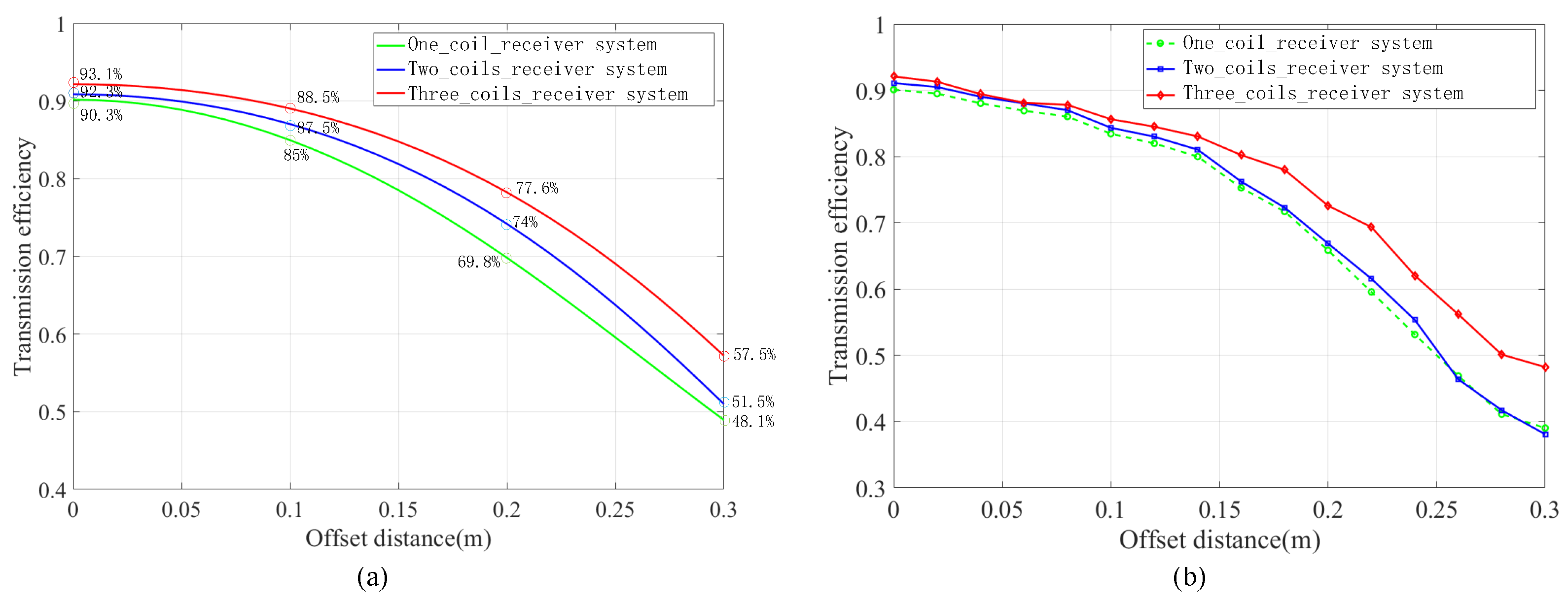
Figure 11 shows the comparative results of the efficiency variation with offset distance . As can be seen from Figure 11, when changes from 0 to 0.3 m, the efficiency of one-coil-receiver system decreases from 90.3% to 48.1%, the efficiency of two-coils-receiver system changes from 92.3% to 51.5%, the efficiency of three-coils-receiver system changes from 93.1% to 57.5%. The three-coils-receiver system is always the most efficient at the same offset distance. This result is caused by the difference in the effective receiving area of the receiver system, therefore the three-coils-receiver system has better stability for offset distance.
5. Conclusions
This paper presents an accurate mutual inductance modeling method of circular coil in different horizontal offset and angular deflection. In this model, the number of turns, the interface diameter and the spaces between turns of coil are considered. Besides, the circuit models which contain one, two and three receiving coils are established. Based on the accurate model of mutual inductance and circuit models, this paper proposes a coil design method which can design the radius and turn number of the coil quantificationally for the WPTS. It is further verified through simulations and experiments that the design of the coil parameters in this paper are successful. In order to realize the system with better anti-offset and anti-deflection ability, this paper designs the receiver with one coils, receiver with two coils, and receiver with three coils using the quantificational model. In the best state, the power and the efficiency of receiver with one coil are 50.3 W and 90.3% respectively, receiver with two coils are 77.5 W and 92.3% respectively, receiver with three coils are 100.8 W and 93.1% respectively. It found that the receiver with three coils in the best state can achieve higher power and efficiency than that of receiver with two coils and receiver with one coil when the deflection angle changes from 0 to and horizontal offset distance changes from 0 to 0.3 m. The anti-deflection and anti-offset properties of the receiver with three coils is better than that of the receiver with two coils and the receiver with one coil. Therefore, it is expected that the proposed multi attitude reception magnetic coupling resonance WPTS can be used to aviation and medical devices.
One problem of Omnidirectional Receiver designed by this paper is that the space occupied is too large. The design of small volume omnidirectional receiver resonator will be further studied in the future.
Author Contributions
Methodology and writing, H.A.; investigation, J.Y.; data curation, J.L.; supervision, L.C. All authors have read and agreed to the published version of the manuscript.
Funding
This research was supported by the National Natural Science Foundation of China under Grant Nos 51677177.
Institutional Review Board Statement
Not applicable.
Informed Consent Statement
Not applicable.
Data Availability Statement
Not applicable.
Acknowledgments
The authors wish to thank and acknowledge support from Key Research and Development Program of Jiangsu (No.BE2022051-3).
Conflicts of Interest
The authors declare no conflict of interest.
References
- Nguyen, M.Q.; Hughes, Z.; Woods, P.; Seo, Y.S.; Rao, S.; Chiao, J.C. Field Distribution Models of Spiral Coil for Misalignment Analysis in Wireless Power Transfer Systems. IEEE Trans. Microw. Theory Tech. 2014, 62, 920–930. [Google Scholar] [CrossRef]
- Zhang, B.; Xu, W. Review of low-loss wireless power transfer methods for autonomous underwater vehicles. IET Power Electron. 2022, 15, 775–788. [Google Scholar] [CrossRef]
- Zhang, X.Y.; Xue, C.D.; Lin, J.K. Distance-Insensitive Wireless Power Transfer Using Mixed Electric and Magnetic Coupling for Frequency Splitting Suppression. IEEE Trans. Microw. Theory Tech. 2017, 65, 4307–4316. [Google Scholar] [CrossRef]
- Hu, H.; Georgakopoulos, S. Multiband and Broadband Wireless Power Transfer Systems Using the Conformal Strongly Coupled Magnetic Resonance Method. IEEE Trans. Ind. Electron. 2017, 64, 4307–4316. [Google Scholar] [CrossRef]
- Lei, Z.; Thrimawithana, D.J.; Madawala, U.K.; Hu, P.; Mi, C.C. A Misalignment Tolerant Series-hybrid Wireless EV Charging System with Integrated Magnetics. IEEE Trans. Power Electron. 2018, 34, 1276–1285. [Google Scholar]
- Ming, L.; Fu, M.; Yong, W.; Chengbin, M.A. Battery Cell Equalization via Megahertz Multiple-Receiver Wireless Power Transfer. IEEE Trans. Power Electron. 2017, 33, 4135–4144. [Google Scholar]
- Wang, S.; Hu, Z.; Rong, C.; Lu, C.; Chen, J.; Liu, M. Planar Multiple-Antiparallel Square Transmitter for Position-Insensitive Wireless Power Transfer. IEEE Antennas Wirel. Propag. Lett. 2018, 17, 188–192. [Google Scholar] [CrossRef]
- Cheng, H.; Kawajiri, T.; Ishikuro, H. A 13.56-MHz Wireless Power Transfer System With Enhanced Load-Transient Response and Efficiency by Fully Integrated Wireless Constant-Idle-Time Control for Biomedical Implants. IEEE J. Solid-State Circuits 2017, 53, 538–551. [Google Scholar]
- Kim, J.; Kim, D.H.; Park, Y.J. Free-Positioning Wireless Power Transfer to Multiple Devices Using a Planar Transmitting Coil and Switchable Impedance Matching Networks. IEEE Trans. Microw. Theory Tech. 2016, 64, 3714–3722. [Google Scholar] [CrossRef]
- Jayathurathnage, P.K.S.; Alphones, A.; Vilathgamuwa, D.M.; Ong, A. Optimum Transmitter Current Distribution for Dynamic Wireless Power Transfer With Segmented Array. IEEE Trans. Microw. Theory Tech. 2018, 66, 346–356. [Google Scholar] [CrossRef]
- Dan, J.; Yong, Y.; Liu, F.; Ruan, X.; Wang, C. Modeling and investigation of magnetically coupled resonant wireless power transfer system with varying spatial scales. IEEE Trans. Power Electron. 2017, 32, 3240–3250. [Google Scholar]
- Guo, Y.; Wang, L.; Zhang, Y.; Li, S.; Liao, C. Rectifier Load Analysis for Electric Vehicle Wireless Charging System. IEEE Trans. Ind. Electron. 2018, 65, 6970–6982. [Google Scholar] [CrossRef]
- Zhao, Z.Q.; Chen, Y.H.; Fu, M.J.; He, C.L.; He, J.J.; Pang, Y.; Li, G.Q.; Lin, J.Z. Analysis of Wireless Energy Transmission Characteristics via Magnetic Resonances Based on Mutual Inductance Model. Appl. Mech. Mater. 2014, 513–517, 3489–3495. [Google Scholar] [CrossRef]
- Xiu, Z.; Ho, S.L.; Fu, W.N. Analysis and Optimization of Magnetically Coupled Resonators for Wireless Power Transfer. IEEE Trans. Magn. 2012, 48, 4511–4514. [Google Scholar]
- Yilmaz, T.; Hasan, N.; Zane, R.; Pantic, Z. Multi-Objective Optimization of Circular Magnetic Couplers for Wireless Power Transfer Applications. IEEE Trans. Magn. 2017, 53, 1–12. [Google Scholar] [CrossRef]
- Zhang, Z.; Zhang, B.; Wang, J. Optimal Design of Quadrature-Shaped Pickup for Omnidirectional Wireless Power Transfer. IEEE Trans. Magn. 2018, 54, 1–5. [Google Scholar]
- Qi, Z.; Mei, S.; Yao, S.; Tang, W.; Hu, A.P. Field Orientation Based on Current Amplitude and Phase Angle Control for Wireless Power Transfer. IEEE Trans. Ind. Electron. 2018, 65, 4758–4770. [Google Scholar]
- SaadMutashar, A.; Hannan, M.A.; Samad, S.A.; Aini, H. Inductive coupling links for lowest misalignment effects in transcutaneous implanted devices. Biomed. Tech. Biomed. Eng. 2014, 59, 257–268. [Google Scholar]
- Cheapanich, S.; Chan, A.; Intani, P. Study of wireless power transfer using series-parallel topology. In Proceedings of the 2017 International Electrical Engineering Congress (iEECON), Pattaya, Thailand, 8–10 March 2017. [Google Scholar]
- Takeda, U. Dual Transmitter Free-Positioning Wireless Power Transfer System with Optimum Switching Phase Detection Technique. In Proceedings of the 2018 IEEE/MTT-S International Microwave Symposium-IMS, Philadelphia, PA, USA, 10–15 June 2018. [Google Scholar]
- Talaat, M.; Metwally, H.M.B.; Arafa, I. Experimental and Simulation Study of Wireless Power Transfer Using Resonators With Coupled Electric Fields. IEEE Trans. Plasma Sci. 2018, 46, 2480–2487. [Google Scholar] [CrossRef]
- An, H.; Liu, G.; Li, Y.; Zhang, C. The transmission characteristics study of multi attitude reception magnetic coupling resonance wireless energy transmission system. In Proceedings of the 2018 IEEE MTT-S International Wireless Symposium (IWS), Chengdu, China, 6–10 May 2018; pp. 4108–4117. [Google Scholar]
- Su, Y.P.; Liu, X.; Hui, S.Y.R.; Su, Y.P.; Liu, X. Mutual Inductance Calculation of Movable Planar Coils on Parallel Surfaces. IEEE Trans. Power Electron. 2009, 24, 1115–1123. [Google Scholar] [CrossRef]
- Kerber, A.F.; Saitta, F.; Bristow, P.; Vernet, J. Mutual Inductance Calculation Between Circular Filaments Arbitrarily Positioned in Space: Alternative to Grover’s Formula. IEEE Trans. Magn. 2010, 46, 3591–3600. [Google Scholar]
- Babic, S.; Akyel, C. New Formulas for Mutual Inductance and Axial Magnetic Force Between Magnetically Coupled Coils: Thick Circular Coil of the Rectangular Cross-Section-Thin Disk Coil (Pancake). IEEE Trans. Magn. 2013, 49, 860–868. [Google Scholar] [CrossRef]
- Wu, J.; Dai, X.; Sun, Y.; Li, Y. A Node Role Dynamic Change Method Among Repeater, Receiver, and Decoupling Using Topology Switching in Multinode WPT System. IEEE Trans. Power Electron. 2021, 36, 11174–11182. [Google Scholar] [CrossRef]
- Reza, K.S.; Kumar, P.S.; Desmulliez, M.P.Y. Accurate Modeling of Coil Inductance for Near-Field Wireless Power Transfer. IEEE Trans. Microw. Theory Tech. 2018, 66, 4158–4169. [Google Scholar]
Figure 1.
The diagrammatic sketch of the proposed structure.
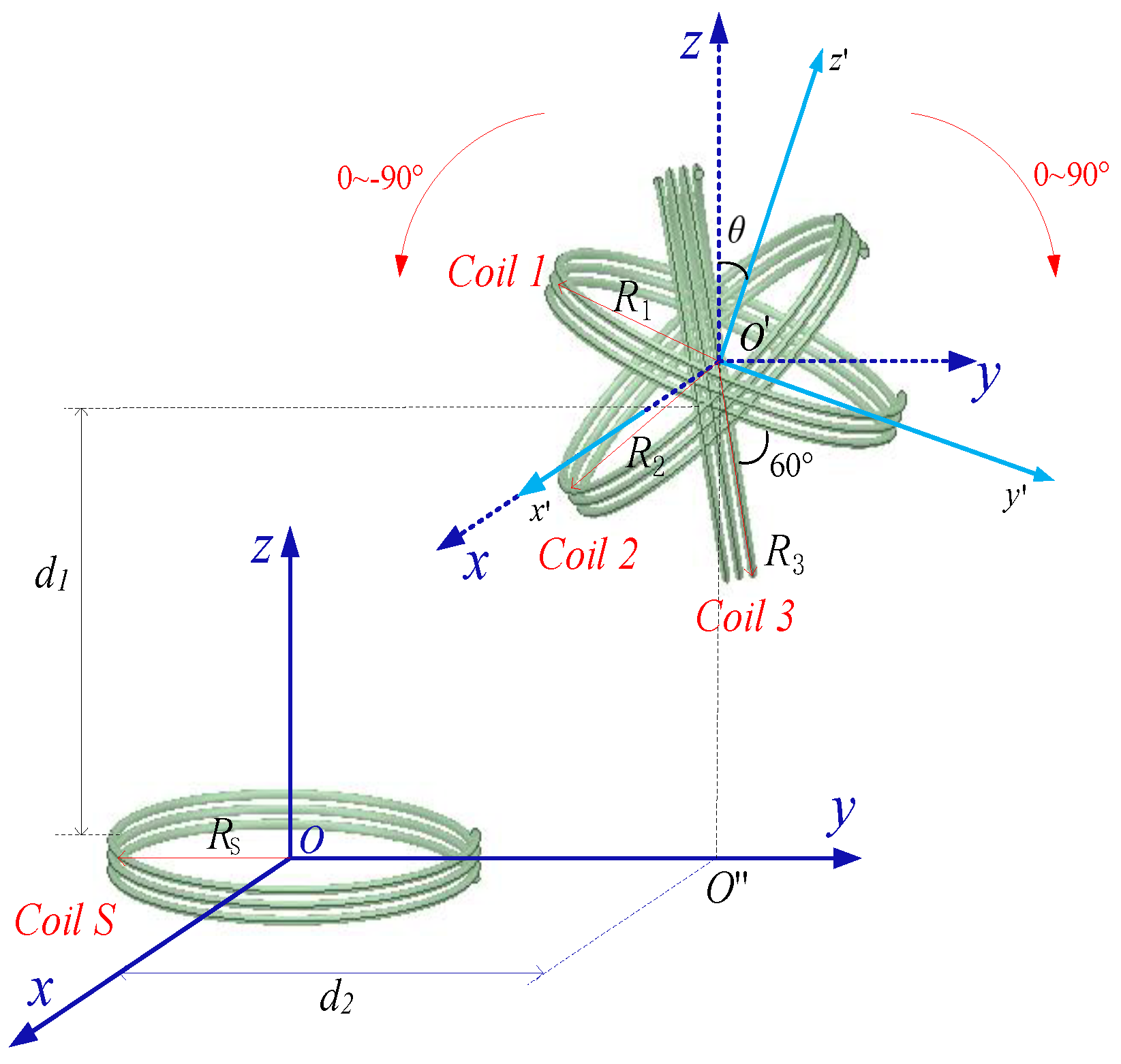
Figure 2.
The circuit model of three-coils-receiver system.
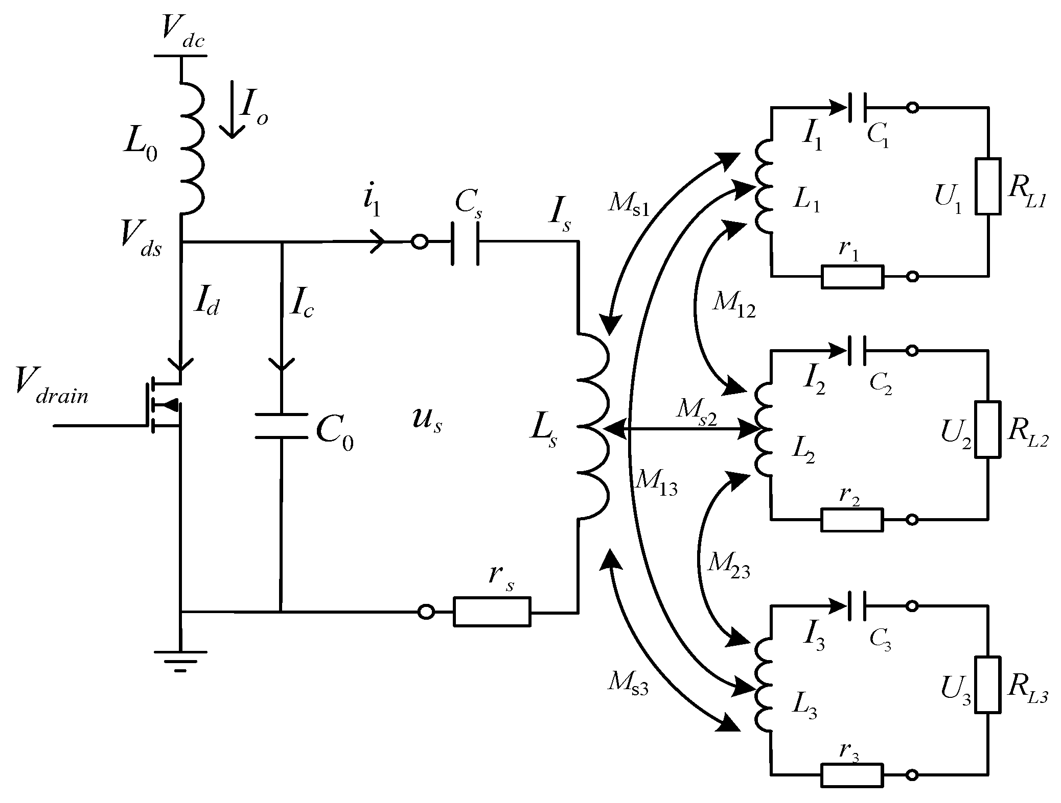
Figure 3.
One loop model of perfectly aligned coils.

Figure 4.
The diagrammatic sketch of perfectly aligned coils. (a) is the diagrammatic sketch. (b) is the cross section diagram of (a).
Figure 4.
The diagrammatic sketch of perfectly aligned coils. (a) is the diagrammatic sketch. (b) is the cross section diagram of (a).
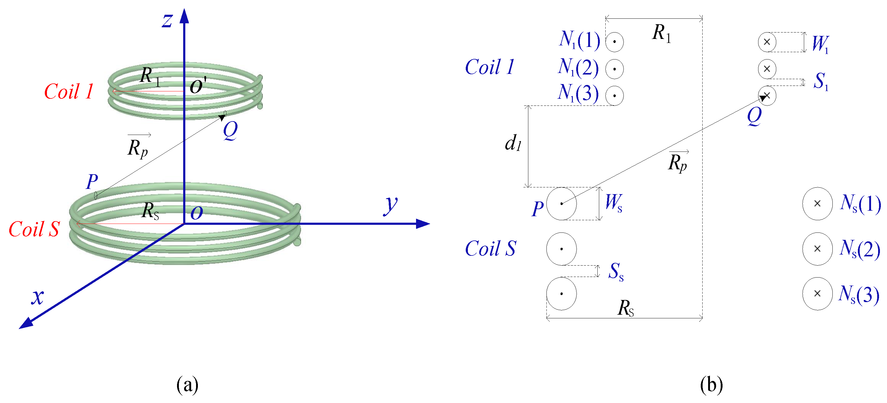
Figure 7.
Transmission characteristics of three-coils-receiver system vary with coil diameter and number of turns. x-axis is the number of turns N, y-axis is diameter 2R. , , = 0. The performance indexes in (a,b) are load power and transmission efficiency; (c) is the sectional view of (a) where the power is equal to 50 W; (c) is the sectional view of (a) where the power is equal to 50 W; (d) is the sectional view of (b) where the transmission efficiency is equal to 90%.
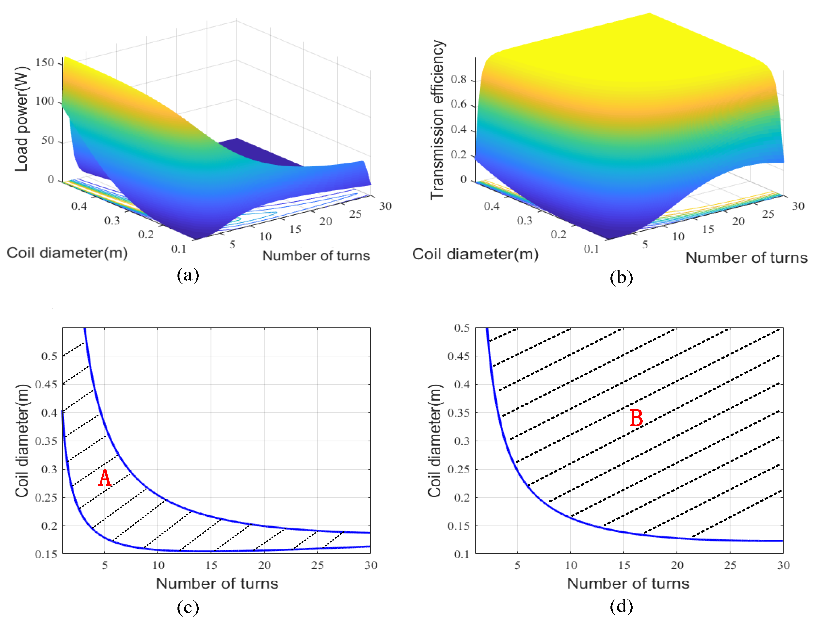
Figure 8.
Measurement setup of three-coils-receiver system.
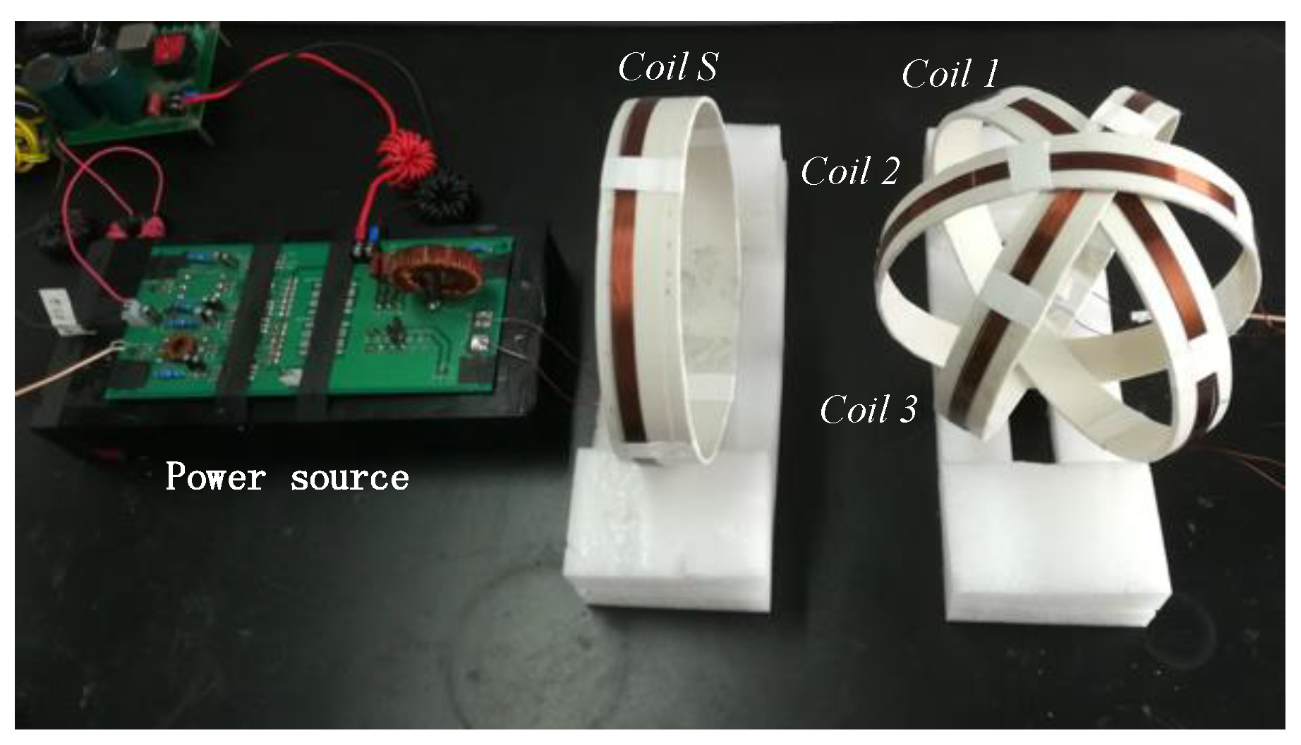
Figure 9.
The transmission characteristics of receiver with three coils vary with deflection angle. The pitch rotation angle , R = 10 cm, N = 11, = 15 cm, = 0. (a) shows the load power varies with deflection angle. (b) shows the efficiency varies with deflection angle. The simulation is completed by Matlab.

Figure 10.
The transmission characteristics of receiver with one coil and two coils vary with offset distance. (a,b) are the diagrammatic sketch of the one-coil-receiver system and two-coils-receiver system, respectively. (c,d) show the transmission efficiency of one-coil-receiver system and two-coils-receiver system vary with deflection angle , respectively. In both systems, the pitch rotation angle , R = 10 cm, N = 11, = 15 cm, = 0. The simulation is completed by Matlab.

Figure 11.
Comparison of efficiency vary with offset distance. (a) is the simulation result, and (b) is the experimental result. The of one-coil-receiver system, two-coils-receiver system and three-coils-receiver system are , , and respectively.
Figure 11.
Comparison of efficiency vary with offset distance. (a) is the simulation result, and (b) is the experimental result. The of one-coil-receiver system, two-coils-receiver system and three-coils-receiver system are , , and respectively.

Table 1.
Coil Parameters Of three-coils-receiver system.
| System | R | N | W | S | f | ||||
|---|---|---|---|---|---|---|---|---|---|
| three-coils-system | 10 | 11 | 2 mm | 0.2 mm | 15 cm | 0 | 403 | 0 to | 1 MHz |
Table 2.
Coil Parameters Of one-coil-receiver system and two-coils-receiver system.
| System | R | N | W | S | f | ||||
|---|---|---|---|---|---|---|---|---|---|
| two-coils-system | 10 | 11 | 2 mm | 0.2 mm | 15 cm | 0 | 403 | 0 to | 1 MHz |
| one-coil-system | 10 | 11 | 2 mm | 0.2 mm | 15 cm | 0 | 403 | 0 to 2 | 1 MHz |
Table 3.
Comparison of efficiency achieved in other papers.
| Ref. | Receiver | |||||
|---|---|---|---|---|---|---|
| This paper | three coils | 93.13% | 92.12% | 92.58% | 93% | 92.3% |
| This paper | two coils | 90.2% | 91.4% | 92.3% | 91.2% | 90.1% |
| This paper | one coils | 90.2% | 87.4% | 78.2% | 50.3% | 19.9% |
| [18] | three coils | 26.85% | 28.67% | 33.6% | 32.26% | 25.09% |
| [22] | two coils | 90.2% | 91.4% | 91.8% | 90.5% | 89.8% |
| [19] | one coil | 55% | 32% | 17% | 8% | 5% |
| [20] | one coil | 65% | 62% | 56% | 50% |
Publisher’s Note: MDPI stays neutral with regard to jurisdictional claims in published maps and institutional affiliations. |
© 2022 by the authors. Licensee MDPI, Basel, Switzerland. This article is an open access article distributed under the terms and conditions of the Creative Commons Attribution (CC BY) license (https://creativecommons.org/licenses/by/4.0/).
Share and Cite
MDPI and ACS Style
An, H.; Yuan, J.; Li, J.; Cao, L. Design and Analysis of Omnidirectional Receiver with Multi-Coil for Wireless Power Transmission. Electronics 2022, 11, 3103. https://doi.org/10.3390/electronics11193103
AMA Style
An H, Yuan J, Li J, Cao L. Design and Analysis of Omnidirectional Receiver with Multi-Coil for Wireless Power Transmission. Electronics. 2022; 11(19):3103. https://doi.org/10.3390/electronics11193103
Chicago/Turabian StyleAn, Huilin, Jian Yuan, Jun Li, and Liqiang Cao. 2022. "Design and Analysis of Omnidirectional Receiver with Multi-Coil for Wireless Power Transmission" Electronics 11, no. 19: 3103. https://doi.org/10.3390/electronics11193103
Note that from the first issue of 2016, this journal uses article numbers instead of page numbers. See further details here.