Review

Key Factors in the Implementation of Wearable Antennas for WBNs and ISM Applications: A Review WBNs and ISM Applications: A Review

by
Fatimah Fawzi Hashim
1,2,
Wan Nor Liza Binti Mahadi
1,2,*,
Tariq Bin Abdul Latef
1,2 and
Mohamadariff Bin Othman
1,2
1
Department of Electrical Engineering, University Malaya, Kuala Lumpur 50603, Malaysia
2
Electromagnetic Radiation & Devices Research (EMRD), Faculty of Engineering, University Malaya, Kuala Lumpur 50603, Malaysia
*
Author to whom correspondence should be addressed.
Electronics 2022, 11(15), 2470; https://doi.org/10.3390/electronics11152470
Submission received: 27 June 2022 / Revised: 21 July 2022 / Accepted: 27 July 2022 / Published: 8 August 2022
(This article belongs to the Section Microwave and Wireless Communications)

Abstract

:
The increasing usage of wireless technology has prompted the development of a new generation antenna compatible with the latest devices, with on-body antennas (wearable antennas) being one of the revolutionary applications. This modern design is relevant in technologies that require close human body contact, such as telemedicine and identification systems, due to its superior performance compared to normal antennas. Some of its finer characteristics include flexibility, reflection coefficient, bandwidth, directivity, gain, radiation, specific absorption rate (SAR), and efficiency that are anticipated to be influenced by the coupling and absorption by the human body tissues. Furthermore, improvements like band-gap structure and artificial magnetic conductors (AMC) and (DGS) are included in the wearable antenna that offers a high degree of isolation from the human body and significantly reduces SAR. In this paper, the development of on-body antennas and how they are affected by the human body were reviewed. Additionally, parameters that affect the performance of this new antenna model, such as materials and common technologies, are included as an auxiliary study for researchers to determine the factors affecting the performance of the wearable antenna and the access to a highly efficient antenna.

1. Introduction

The wearable/on-body antenna has undergone rapid development over the years because of its essential application, especially in the medical field, where these devices are directly connected to the human body with remote control features. Figure 1 shows the wireless body area [1]. Antennas are the most important part of these devices, where signals are exchanged without damaging the human body and its environment. Its main function is to track an individual’s health status while being worn on various parts of the body. The new generation of antennas has several advantages, including lightweight, twistable, flexibility and steady performance even when fixed on the irregularly shaped human body.
The human body experiences constant changes in terms of shape and conductivity. When the magnetic field enters and is distributed throughout the body, it is influenced by the body’s physiology, frequency, and polarization, thus enabling the antenna to continuously detect the body compared to its environment [2]. The antenna gain and efficiency are affected by the absorption of the human body because the gain affects the energy sent with radiation direction. Therefore, researchers are attempting to develop various techniques to achieve a high antenna gain leading to maximum efficiency.
The substrate dielectric constant and its thickness decide the bandwidth and efficiency of a patch antenna. The dielectric constant of the substrate should range between 2.2 ≤ εr ≤ 12, which lowers the dielectric constant and increases spatial waves; the decreasing of the surface wave losses is contributed by the low dielectric constant connected to guided wave propagation within the antenna substrates and that resulting in a high impedance bandwidth of the antenna [2]. Meanwhile, substrate thickness normally ranges from 0.003 λ to 0.005 λ, where λ is the wavelength used to increase antenna bandwidth [3]. Regarding the dissipation factor (Loss tangent tan δ), the higher the loss tangent values, the more lossy the dielectric substrate will be, thus determining radiation efficiency [2].
In this paper, the wearable antenna history and specific absorption rate (SAR), antenna radiation on the human body, materials and methods used in their manufacture are discussed. Then, the effect of these factors on the antenna gain and the common techniques and styles used to obtain a high gain suitable for applications related to the human body were analysed.

2. Historical Review of Wearable/Cloth Antenna

Wearable antennas are not new to the market, but their lack of efficiency has limited their application in performing the increasingly complex tasks required over the years. Researchers and manufacturers continue to search for new methods to enhance its features for better utilisation. Nevertheless, several challenges needed to be overcome, including curves of the human body and environmental factors such as humid weather that may directly affect the device’s performance. Measures that have been taken to improve wearable antennas’ performance include utilising cloth material, installing reflectors adjacent to the antenna and position slots in the antenna ground. The focus is now on designing antennas that can be implanted in clothing such as hats, shirts or shoes to encourage human-related applications.

Dielectric Permittivity Parameter Measurement

Textile dielectric permittivity can be measured in numerous ways, and each can be determined using different algorithms. The correct choice affects accuracy, convenience, frequency range, measuring speed, etc. [4].
Methods for measuring permittivity:
  • Parallel plate method;
  • Transmission/reflection line method;
  • Open-ended probe method;
  • Free space method;
  • Resonant (Cavity) Technique;
  • Microstrip patch antenna covered with the material under test.
High-frequency permeability is measured using the resonant (cavity) approach; the parallel plate method is another high-accuracy method. These methods have a small frequency range, and this shortcoming limits the utility of these methods to analyse broadband textile transmission line substrate dielectric constant variations. Cotton cloth has the largest dielectric constant and loss, according to preliminary data [4].
The wearable antenna can be designed and coated with different materials like alloys, inkjet, and polymer-embedded fabrics, depending on its application and requirement. For instance, textiles are suitable for body wearable antennas built into the clothes. Table 1 illustrates the dielectric properties of normal fabrics.
Fabric antennas require a conducting material to function as a radiator, which is essential for their electrical characteristics [3]; thus, the electric and electromagnetic features of the materials are crucial in antenna design. Alternately, microstrip patch antennas are lightweight and robust, with a low fabrication cost, and are easy to integrate with radio frequency; hence, they are a good candidate for body-worn applications [5].
Flexibility and easy installation in clothes are the main factors of wearable antennas used in the wireless personal area network (WPAN). Furthermore, substrate dielectric constant and its thickness have major impacts on antenna bandwidth and efficiency. To enhance microstrip bandwidth, the substrate thickness for a fixed, relative permittivity is chosen [5]. However, antennas are sensitive to moisture. When an antenna fabric absorbs water, the high dielectric constant of water alters the antenna parameters. Since the textile antennas are in contact with the skin, the probability of the antenna absorbing moisture like sweat is very high. Moreover, there is a risk for antennas to get wet when the clothing is washed. Beyond these effects, tightening the fabric is easier than the other systems [5]. The fabrication technique for each textile material differs. In the textile adhesive technique, the liquid textile adhesive is used to cover the wearable antenna surface. In contrast, the more common sewing technique causes wrinkle formations on the fabric surface. This fabrication technique is also known as computer-aided design (CAD), where a picture is uploaded into software as an embroidery guide for the sewing process.
Table 2 shows the materials used to design wearable antennas. Common materials used in the design of wearable antennas were compared with the most important factors affecting the antenna’s performance in terms of the wettability, flexibility, weight and cost to select the best material.
The designed antenna in [6] achieved a high gain of 6.45 dBi and a Front to Back Ratio (FBR) of 15.8 dB. An e-slot antenna with an electromagnetic band-gap (EBG) and Defected Ground Structure (DGS) printed it into a highly flexible fabric (DGS). On the other hand, fragile conductive inks and/or copper tape were used in [7] state-of-the-art origami antenna techniques. A copper-equivalent textile-based body-worn antenna [8] was shown to have excellent agreement between simulations and measurements for all e-textile prototypes. E-fibres (metal-coated polymer fibres) and copper were used to make the antenna’s specified antenna. In the end, both antennas were analyzed, and it was determined that the cloth antenna performed just as well as its copper counterpart, with achieved gains of around two decibels.
Table 3 compares the antennas from two decades ago with their current predecessors, where the former fared poorly due to some unsuitable materials incorporated in its manufacture. Antenna performance is classified as high, medium or low, based on parameters such as profit and bandwidth (high when the gain > 4; medium when the gain > 2; low when the gain < 2).

3. Embroidered Textile Antennas

The demand for lighter and more compact personal electronic devices drives the development of wearable electronics and antennas. The incorporation of antennas into everyday clothing would allow for the practicality of smaller, more portable electronic devices without compromising their performance. There are many uses for wearable antennas, including military, aerospace, rescue, medicine, fashion, etc. [29]. Consumers will appreciate the convenience of the system’s hands-free operation. Antennas that may be worn as part of clothes that are soft and flexible are often constructed from thin, stretchy conductors [30,31,32]. For wearable antennas, the trade-off between fabric properties and antenna performance is a major issue.
Connecting personal communications, wireless sensors, and other wireless devices to wireless networks or the “Internet of Things” requires a huge number of antennas. Currently, antennas are integrated into a variety of gadgets, as well as the human body and clothing [30] and this trend will continue in the future. These antennas must be lightweight and bendable. To enable the seamless integration of conventional antennas with clothes, conventional materials like metals and dielectrics must be substituted for conductive and nonconductive fabrics and yarn. Full-textile antennas are antennas constructed entirely from conductive and non-conductive textiles and yarn. Water and water vapour rapidly enter porous conductive and non-conductive fabrics, causing higher losses and dielectric property changes. Changes in input impedance, gain, and radiation patterns result [30].

3.1. Types of Conductive Threads

Conductive thread conducts electricity and the textiles are wired. Thomas Edison employed this technology. Carbonized thread satisfies the resistance and lifespan requirements. Conductive threads serve antistatic, electromagnetic shielding, wearables, e-textiles, etc. functions. When sewn onto flexible textiles, they provide a conductive connection like wires [31].
In recent years, there has been a great deal of interest in conductive threads. Typically, textiles are manufactured from insulating materials such as polymers and cottons. Textile threads are made conductive for a variety of purposes; the objective is to achieve EM shielding. Due to their weak conductivity, the surface of insulated textiles accumulates electrical load. Turning the threads conductive makes load transfer and EM shielding possible. Another advantage of conductive threads is their use as wires or connectors in a variety of applications [33,34,35,36].
Conductive threads fall into two distinct kinds. There are first intrinsic conductive threads that are composed of conductive fibres. Textiles are composed of conductive materials such as metals (gold, silver, nickel, and steel), or graphite, which can take the shape of wires or threads. They are injected into the structure of textiles or used intrinsically. Each strand is composed of the physically conducting fibre. Metal, graphite, conductive polymers, carbon nanotubes, and other materials are utilised to create these fibres. They have great conductivity but face several obstacles and are heavier and more expensive. Additionally, their structure can damage embroidery equipment because they are less flexible and user-friendly than conventional fabrics. Low-resistance stainless steel is the most popular. These threads are hard to use in a sewing machine as they break while running through needles. Intrinsically conductive polymers include Polyanyline, Polypyrrole, PVA, and PA11. They are thermochemically and environmentally stable. Their remarkable conductivity has drawn notice recently. They are flexible, light, and conduct well, but due to their great cost, they are generally used in research [35,36,37].
Coated conductive threads are second. Conductive metals like copper, gold, silver, or carbon are implanted or coated onto nonconductive textile cores. Cotton, polymers, or nylon are typical core materials. Various procedures are used to apply these coatings. Coating textiles with metals or conductive materials creates a hybrid. Galvanic coatings are conductive. They face obstacles such substrate suitability, limited adhesion, and corrosion resistance. Metallic salt is another coating technique. This approach reduces conductivity. Coating textiles with metals or other conductive components provides numerous properties; it boosts conductivity and improves structure. Medical, fashion, military, architecture, etc. can use them as they are functional and beautiful. Combining textile core and coating allows stitching. This group’s resistance varies by coating material and thickness [31]. Conductive threads are uninsulated and covered with different materials and ply numbers. Not as efficient as a wire, yet it allows current to travel through, removing the need for circuit boards [31].

3.2. Challenges in Embroidered Antennas

The challenges of fabricating embroidered antennas are: choose out the best conductive thread for the patch antenna based on factors like conductivity, strength, flexibility, and how the threads behave when stitched together to make an approximately continuous item. Understanding the flow of current on a patch antenna is essential to determine the stitching direction. Increasing antenna efficiency can be achieved by aligning the primary current flow with the stitch direction [32]. This can create further difficulties if the design needs to operate at higher modes when the current is flowing perpendicularly, as well as for more intricate systems where the current is flowing in multiple directions. The effect of different stitching geometry on antenna performance is explored and published in [33]. In general, the tighter the stitching spacing, the greater the efficiency of the antenna. This comes at the cost of decreased flexibility and greater thread length, which immediately results in higher manufacturing costs. The influence of stitching type on the performance of dipole antennas is described and proven in [38,39,40] where dipole tag-antennas embroidered with varied thread densities and two different stitch patterns are examined. The authors of [34] describe the embroidery aspects of Ultra High Frequency (UHF) Radio-Frequency Identification (RFID) antenna [32]. Table 4 illustrates some recent research projects in embraided antenna and manufacturing techniques.

4. SAR and Antenna Performance with the Human Body

Previous studies have reported the satisfactory performance of wearable antennas in free space, but the same cannot be said when the device is used in proximity with the human body due to frequency shifts and radiation absorption. These drawbacks are contributed by the high theta and decedent dielectric properties of the human body compared to free space [45]. There is a gap in the literature concerning these issues, especially on the effectiveness of dielectric characteristics on the technical performance of wearable antennas.
The on-body performance of the wearable antenna is ranked by quantifying the changes in its input impedance and near-field distribution that are mainly caused by the presence of lossy dielectric material. When the wearable antenna was tested on phantom body fat, there was a 17% increase in impedance, 19% increase in phantom muscle and 20% for the phantom blood. The methods in [45] are recommended in analysing and validating the reason for behaviour degradation when an antenna is operated close to the human body. All these findings are crucial for antenna designers to select the best location for the on-body antenna.

Impact of EM on Human Body

Modern electrical appliances are increasing the influence of electromagnetic field (EMF) radiation on humans, and studies reveal the electromagnetic field’s impact on human health [46]. In laboratories specializing in the study of antennas, students and researchers are exposed to EMF radiation from the antennas they are studying or manufacturing. On the other side, this absorption that occurs through the human body weakens the performance of the antenna. Fluorescent light emits EM radiation between 380–800 nm, while UV radiation is 100–400 nm, altering DNA sequence and gene expression. Some people have become electromagnetic radiation sensitive after prolonged exposure to electronic equipment. Some researchers experienced stress, CFS, focus difficulty, allergies, depression, and sleep disturbances. Chronic fatigue syndrome (CFS) is a depressed immune system linked to ELFE. Low- and high-frequency EMF also doubles infection resistance, according to studies.

5. Techniques

Researchers have developed techniques to increase antenna performance. Most techniques that have been proven effective are discussed in this paper.

5.1. AMC Array Reflector

Artificial magnetic conductors (AMCs) technique can also be referred to as electromagnetic band-gap structures (EBGs) and high impedance surfaces (HISs) that act as a support shield to the wearable antenna. They reduces the waves on the antenna surface resulting in a significant decrease in absorption of radiation by the human body, thus improving antenna gain and front to- back ratio (FBR) [47]. An AMC surface can be a ground plane in some discrete antenna applications [48]. The reflector size is the main component in determining the antenna performance, while an antenna design with multiple layers makes a high-profile antenna system [8].
These structures produce antennas with high gain, low profile, and great efficiency. EBG has sparked interest in the antenna field. EBG structures lower surface wave current, hence enhancing the antenna’s performance. Surface waves diminish the antenna’s performance [49].
EBG-technique surface wave suppression enhances antenna performance by enhancing antenna gain and antenna efficiency.
It has two interesting characteristics over the frequency range known as a band gap, according to [50] To begin, the reflected wave has the same amplitude as the incident wave. The EBG surface has a similar function to PMC, which does not exist in nature but has a 00-phase reflection. Second, it prevents the propagation of surface waves. EBG has a wide range of applications in antenna design because of its ability to solve typical antenna problems and optimise performance.

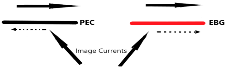
5.1.1. In-Phase Reflection

The antenna depicted in Figure 2 is a simple wire antenna placed above a PEC ground plane. Under a perfectly conducting electric ground plane, the image current is out of phase with the wire current. In the presence of an EBG or PMC, the subsurface image current would be in phase with the wire current, thereby enhancing the antenna’s radiation. EBG operates as an AMC with a reflection phase of +1 (in-phase reflection), as opposed to the conventional metal ground plane, which has a reflection phase of −1 (out-of-phase reflection) (out of phase). The EBG can therefore function as a reflector, capable of redirecting the vast majority of energy in the desired direction.

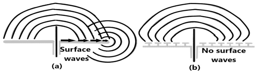
5.1.2. Suppressing of Surface Wave

Figure 3 illustrates another characteristic of the EBG surface. It can be used to eliminate the radiation emitted by the ground planes. An “artificial impedance surface” with certain band-gap characteristics inhibits the propagation of surface waves generated by the antenna.
The radiation pattern of a monopole antenna on a metallic ground plane is depicted in Figure 4a. Significant characteristics of the antenna pattern include ripples in the forward direction and power loss in the reverse direction.
The surface wave that travels away from the antenna and radiates from the level edges of the ground is responsible for both of these properties. An EBG ground plane is presented in Figure 5b, as a way to reduce the surface wave; as a result, the opposite hemisphere receives less energy and the radiation pattern is more uniform.
In one form, an EBG material is a periodic structure with a high impedance for the propagation of electromagnetic waves within a specific frequency range. In antenna applications, the antenna can utilise the high impedance or surface wave band gap of an EBG within a specific frequency band. It has been discovered that EBG-structured antennas give significant advantages over conventional antennas [50].

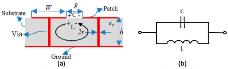
5.1.3. EBG Principle

Typically, EBG structures are periodic cells composed of dielectric components or metal. Sievepiper introduced an EBG structure resembling a mushroom for the first time [52]. According to Figure 5, the structure comprises a dielectric substrate, metal patches, a ground plane, and connecting vias.
The operating mechanism of the EBG structure, as depicted in Figure 6, can be explained by an array of LC filters or a parallel resonant circuit. Capacitance is produced by the space between two adjacent patches, whereas inductance is generated by a current loop within the structure through the pin vias. The inductance in an EBG without vias is caused by the ground plane’s close proximity to the capacitive array of patches [50].
The values of the capacitance (C), inductance (L), bandwidth (BW) and resonant frequency (fr) are given by [50]:
L = μ 0 h
C = w ε 0 1 + ε r π cosh 1 w + g g
f r = 1 2 π LC
BW = 1 ŋ 0 L C
Patch width (W) determines permeability (μ0), permittivity (ε0), and impedance (η0), all in terms of free space, while g determines the distance between neighbouring patches (g).
Z is the surface impedance at resonance, and it is calculated as follows:
Z s = j ω L 1 ω 2 LC
Equations (1)–(5), based on which the parameters of the EBG design were evaluated, [31]. They were the thickness, permittivity, unit cell spacing, and patch width of the substrate. Formula reveals that at low frequencies, the unit cell is typically inductive and so supports the Transverse Magnetic (TM (solid red line)) surface wave. Transverse Electric (TE) waves became dominant as the excitation frequency increased, causing the unit cells to go from resonant to capacitive in a short time. It was found that the surface’s impedance was high in a limited frequency region near the resonance frequency. Figure 7 illustrates how the structure inhibited the propagation of surface waves (TE and TM) and directed them toward the frequency band gap (EBG behaviour) [51]. Surface waves were suppressed and more of the system’s energy was reflected because of the high level of mismatch [50].
In [53], a dual-band antenna, 3.5 GHz and 5.8 GHz, backed with a 4 × 4 AMC array, Rogers ULTRALAM 3850 were used for antenna substrate and RO3003 printed as a substrate on AMC array. When measurements were taken at 15 mm from the human body, acceptable gain and SAR were obtained, but after applying a 4 × 4 AMC array over a gap of 1 mm from the human body, the gain was improved by 23.3 dBi and 13.9 dBi, respectively, for both frequencies, while the SAR was reduced by almost 99%. In [48], the designed textile antenna is operated at two frequencies, 2.44 GHz and 5.00 GHz, using an EBG to improve the antenna gain by 3 dB and decreasing backward radiation by 10 dB.
In another study [54], a 92 × 69 mm dual-band antenna showed a stable gain in the passband. The proposed antenna was designed with a small AMC plane in the shape of a square containing a small double square unit integrated with a bow tie for ISM applications. Meanwhile, [55] developed an Artificial Magnetic Conductor (AMC) plane by using different materials (textiles), and both antennas were able to radiate with SAR lower than 2 W/kg (European regulatory standards).
In [56] a wideband monopole antenna array is presenting with uniplanar compact electromagnetic band gap (UC-EBG) structure for high frequency (4.5–6.5 GHz) and high gain of 11.8–13.6 dBi. Moreover, a maximum 1 g SAR value of 0.49 W/kg at 4 GHz and 1 g SAR value of 0.59 W/kg at 6 GHz are achieved when place the antenna at 8 mm away from the human body, which is much lower than FCC standard, guaranteeing the safety for wearable application. The proposed wideband and high-gain wearable antenna array offers some advantages in the wearable application.

5.2. Photonic Band-Gap (PBG) Technique
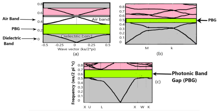
The PBG method has advanced rapidly in the last few years. Resonant cavities, such as the PBG’s periodic flaws, can alter the propagation of electromagnetic waves. PBG provides a stopband at a given frequency within the forbidden band gap [50,57].
PBG has been claimed to improve the directivity of antennas, the suppression of surface waves, and the reduction in harmonics.
Because of the periodicity, dielectric contrast, pattern and the repeating spacing between “atoms,” PBG is able to stop and reduce the transmission of any electromagnetic wave in a frequency range for space direction [58]. There is no longer a need for additional circuitry in antennas to improve performance, as PBG and PC structures and photonic crystals (PCs) eliminate the requirement for additional weight and size-inducing stop bands by reducing surface wave propagation [59]. Antenna substrates, ground, and covers can all benefit from PBG’s ability to reflect radiations in all directions, resulting in increased gain and reduced return loss [60].

PBG Principle

PBG has periodic permittivity. PBG materials are also called photonic crystals due to their closeness to semiconductor physics, where a crystal lattice corresponds to a periodic arrangement of atomic potential [57] (PC). Permittivity periodicity accomplishes for photons what atomic potential does for electrons. Photonic crystal form and index contrast influence many of its optical properties, much as semiconductor conduction qualities. By controlling these two parameters, light may be made to pass through some materials and not others. Scale affects frequency ranges.
Reducing a periodic lattice’s elementary cell size raises its frequency spectrum. This allows photonic crystals to be designed for the infrared or visible spectrum. A PBG material for 1–5 GHz has a few millimeters elementary cell size and is easy to build experimentally. The same infrared photonic crystal has 1 m and 0.1 m cell sizes. This frequency range is approximated by swapping the Y-axis, which shows energy data, for frequency, or by computing the spectrum, which is a photonic crystal’s reflection coefficient. 1D, 2D, and 3D PBG topologies are shown in Figure 8 [57]. This image depicts banned bands. 3D PBG materials are lossless isotropic mirrors for one or more frequency bands. A 2D PBG material behaves as a two-way mirror, as seen in Figure 9. The same substance is transparent at complementary frequencies [57].
The authors of [61] designed a millimeter-wave antenna to improve the antenna patch; PBG substrate and superstrate were created above the radiating element as a cover. Rectangular-shaped Alumina was utilized as a PBG cover to boost gain (from 7.7 dB to 15.52 dB). The same authors [62] designed PBG planar Inverted-F antenna (PIFA). The PBG structure was placed on the substrate (Teflon ε r = 2.65) to decrease surface waves. The design’s impedance bandwidth was 27.5% (1.984–2.621 GHz), a 2.1% improvement from ordinary PIFA. The innovative PBG PIFA may be used in wireless 2.4 and Bluetooth systems.

5.3. Defected Ground Structure (DGS)

The DGS technique stops the wave propagation through the substrate over a frequency range. It makes slots in different sizes or defects on the ground layer of the microstrip patch antenna (MSP). These mistakes or slots may involve one or more DGS arranged horizontally or vertically on an antenna patch.

DGS Principle

Defects in the ground plane alter the flow of current across the ground plane, leading to various consequences. There are a few parameters that are added to a transmission line (or any other construction) in order to change its properties (slot resistance, slots capacitance, slots and inductance) [50]. Three features differentiate the DGS from the PBG: (1) PBG circuit boards have many periodic structures. A few DGS elements may yield similar properties. DGS shrinks circuits; (2) Both DGS and its circuit are easy to develop and implement; (3) Defect-free structures are more precise. DGS unit and periodic DGS improve its effectiveness. Several unique geometries implanted on the ground plane beneath the microstrip line have been documented [63].
By crafting different-shaped slots inside the patch, this approach reduces antenna size and achieves multi-band [44].
In [45], Duroid (tm) substrate was used to design the proposed antenna and improvement in gain was observed after adding DGS to the antenna and bandwidth and return loss enhancement. On the other hand, a 4 GHz microstrip patch antenna was designed using Glass epoxy FR-4 by, which promoted bandwidth enhancement from 105 MHz to 415 MHz and the gain improvement from 4.12 dB to 6 dB. Meanwhile, the proposed antenna by [59] exhibited a simple improvement in the gain, and it was operated at 2.45 GHz for ISM applications with DGS using different flexible materials like felt (dielectric constant 1.36) and Teflon (dielectric constant 2.1) as a substrate for microstrip antenna. Table 5 compares commonly used techniques highlighted in this paper regarding antenna gain, size of the antenna and influence on fabrication. Table 6 shows how these techniques have been used in recent studies.

6. Implemented Wearable Antenna Styles

6.1. Helmet and Vest Antenna

Certain professions require specific conditions, tools and equipment to carry out their tasks; for instance, the police force and fire brigade need hands-free wireless devices. The best solution is to design a wearable antenna that can be incorporated into garments such as helmets or vests, but it has become increasingly challenging with the escalation of bandwidth frequency. In addition, it is important to adhere to the radiation safety mandate while maintaining the low-cost and lightweight feature of antennas and fulfil a wide-bandwidth requirement at the same time. The vest and helmet antennas are examples of wide-bandwidth antennas application that matched the needs of their users.
The safety of the wearer is a top priority in antenna design and applications: i.e., in military applications, the fabric antenna is built-in within the helmets. The research in [82] describes how it is better to use air gap to protect users’ heads in new military applications instead of energy-absorbing foam. An omnidirectional helmet was introduced by [83] by utilizing the whip antenna with much higher and wider bandwidth, connectivity stability, and flexibility, to be worn on humans than other models. On top of that, the helmet antenna has other benefits like the loss due to the helmet is estimated to be less than 1 dB. Further impedance matching would enhance its gain by 0.2 to 1.2 dB, depending on the operating frequency.

6.2. Wearable Monopole and Zip Antenna

A zip antenna is designed to realize a monopole antenna which is widely used in clothes. It is recommended to implement a hidden antenna in a pocket; hence, a pocket zip is preferred for practical considerations. This type of wearable antenna (zip antenna) results in the good performance of Wi-Fi communication systems. The felt material is one of the most commonly used materials to fabricate this type of antennas; for instance, in [3], the textile monopole antenna was designed as a zip antenna operated at 2.5 GHz. A prototype was fabricated and characterised based on the return loss and radiation pattern. It was found that the antenna operated well within 2.4 to 2.7 GHz and suitable for Wi-Fi applications.

6.3. Cloth Antenna (Implemented on Clothes)

The usage of the UHF band is preferred in long-range communication devices due to its good propagation characteristics, as such can be found in Industrial Scientific and Medical (ISM) devices. In some special cases, the radio must be hidden under clothes or implemented on clothes and still maintain the ability to meet the application performance requirements. The antenna design in these applications should be a fabric antenna that can be worn, lightweight and suitable for human body curves to overcome human body effects like radiation and low-profile (below 10 mm) with sufficient bandwidth. For example, [84] implemented a dual-resonance and ultra-wide-band antenna with an operating frequency of 430 MHz with a simple structure and low profile. Figure 10 shows implanted antenna on clothes [85].

7. Conclusions

Wearable antennas design and applications have been discussed, especially in the medical field. In this paper, the focus was on the factors affecting the performance and efficiency of a wearable antenna to avoid the problems faced by antenna designers. It was concluded that the human body has a strong and fundamental effect on the characteristics and performance of the antenna since a certain percentage of the antenna radiation is absorbed. Therefore, the effect of the human body that was discussed must be taken into account. Based on the effect of external operators on the antenna’s behaviour, its manufacture was studied in terms of materials, techniques and shapes that contribute to high efficiency in applications related to human health. Comparisons were made between the common materials and techniques used in manufacturing wearable antennas to maintain their good performance. Based on these comparisons, it is possible to develop antennas with the best specifications and assist the antenna designers in their decision making by considering relevant factors in antenna development. In human activity-related WBNs applications, the future direction for wearable antennas is the production of high-performance fabric substrate antennas that have the capacity to overcome the detrimental effects of the human body.

Author Contributions

Conceptualization, methodology and writing—original draft preparation: F.F.H.; Review and supervision: W.N.L.B.M., T.B.A.L. and M.B.O. All authors have read and agreed to the published version of the manuscript.

Funding

This research was funded by the Faculty Grant (No: GPF038A-2019) of the University of Malaya.

Conflicts of Interest

The authors declare no conflict of interest.

References

  1. Alhayajneh, A.; Baccarini, A.N.; Weiss, G.M.; Hayajneh, T.; Farajidavar, A. Biometric Authentication and Verification for Medical Cyber Physical Systems. Electronics 2018, 7, 436. [Google Scholar] [CrossRef] [Green Version]
  2. Wang, H.; Zhang, Z.; Li, Y.; Feng, Z. A Dual-Resonant Shorted Patch Antenna for Wearable Application in 430 MHz Band. IEEE Trans. Antennas Propag. 2013, 61, 6195–6200. [Google Scholar] [CrossRef]
  3. Mantash, M.; Tarot, A.C.; Collardey, S.; Mahdjoubi, K. Wearable monopole zip antenna. Electron. Lett. 2011, 47, 1266. [Google Scholar] [CrossRef]
  4. Łódzka, P.; Odzieżownictwa Tekstroniki, K. Jacek LEŚNIKOWSKI Dielectric permittivity measurement methods of textile substrate of textile transmission lines. Prz. Elektrotechniczny 2012, 88, 148–151. [Google Scholar]
  5. Singh, V.K.; Singh, A.K.; Yadav, R. Design&Analysis of Bandwidth of Microstrip Patch Antenna for DCS/UMTS Application. Appl. Phy. Lett. 2014, 1, 1108–2349. [Google Scholar]
  6. Ashyap, A.Y.I.; Dahlan, S.H.B.; Abidin, Z.Z.; Dahri, M.H.; Majid, H.A.; Kamarudin, M.R.; Yee, S.K.; Jamaluddin, M.H.; Alomainy, A.; Abbasi, Q.H.; et al. Robust and Efficient Integrated Antenna With EBG-DGS Enabled Wide Bandwidth for Wearable Medical Device Applications. IEEE Access 2020, 8, 56346–56358. [Google Scholar] [CrossRef]
  7. Alharbi, S.; Chaudhari, S.; Inshaar, A.; Shah, H.; Zou, C.; Harne, R.L.; Kiourti, A. E-Textile Origami Dipole Antennas With Graded Embroidery for Adaptive RF Performance. IEEE Antennas Wirel. Propag. Lett. 2018, 17, 2218–2222. [Google Scholar] [CrossRef]
  8. Kennedy, T.F.; Fink, P.W.; Chu, A.W.; Champagne, N.J.; Lin, G.Y.; Khayat, M.A. Body-Worn E-Textile Antennas: The Good, the Low-Mass, and the Conformal. IEEE Trans. Antennas Propag. 2009, 57, 910–918. [Google Scholar] [CrossRef]
  9. Qian, Y.F.R.; Yang, T. Itoh. Novel Planer band gab structures for antenna applications. In Proceedings of the AP2000 Millennium Conferance on Antenna and Propagation, Davos, Switzerland, 9–14 April 2000. [Google Scholar]
  10. Salonen, P. A low-cost 2.45 GHz photonic band-gap patch antenna for wearable systems. In Proceedings of the 11th International Conference on Antennas and Propagation (ICAP 2001), Manchester, UK, 17–20 April 2001; pp. 719–723. [Google Scholar]
  11. Mathian, M.; Korolkewicz, E.; Gale, P.; Lim, E.G. Design of a circularly polarized 2 × 2 patch array operating in the 2.45 GHz ISM band. Microw. J. 2002, 45, 280–285. [Google Scholar]
  12. Salonen, P.; Hurme, L. A novel fabric WLAN antenna for wearable applications. In Proceedings of the IEEE Antennas and Propagation Society International Symposium. Digest. Held in conjunction with: USNC/CNC/URSI North American Radio Sci. Meeting (Cat. No.03CH37450), Columbus, OH, USA, 22–27 June 2003; pp. 700–703. [Google Scholar]
  13. Salonen, P.; Yang, F.; Rahmat-Samii, Y.; Kivikoski, M. WEBGA—wearable electromagnetic band-gap antenna. IEEE Antennas Propag. Soc. Symp. 2004, 1, 451–454. [Google Scholar]
  14. Salonen, P.; Kim, J.; Rahmat-Samii, Y. Dual-band E-shaped patch wearable textile antenna. In Proceedings of the 2005 IEEE Antennas and Propagation Society International Symposium, Washington, DC, USA, 3–8 July 2005; pp. 466–469. [Google Scholar]
  15. Locher, I.; Klemm, M.; Kirstein, T.; Troster, G. Design and Characterization of Purely Textile Patch Antennas. IEEE Trans. Adv. Packag. 2006, 29, 777–788. [Google Scholar] [CrossRef] [Green Version]
  16. Hertleer, C.; Tronquo, A.; Rogier, H.; Vallozzi, L.; van Langenhove, L. Aperture-Coupled Patch Antenna for Integration Into Wearable Textile Systems. IEEE Antennas Wirel. Propag. Lett. 2007, 6, 392–395. [Google Scholar] [CrossRef] [Green Version]
  17. Vallozzi, L.; Rogier, H.; Hertleer, C. Dual Polarized Textile Patch Antenna for Integration Into Protective Garments. IEEE Antennas Wirel. Propag. Lett. 2008, 7, 440–443. [Google Scholar] [CrossRef]
  18. Ouyang, Y.; Love, D.J.; Chappell, W.J. Body-Worn Distributed MIMO System. IEEE Trans. Veh. Technol. 2009, 58, 1752–1765. [Google Scholar] [CrossRef]
  19. Declercq, F.; Rogier, H. Active Integrated Wearable Textile Antenna With Optimized Noise Characteristics. IEEE Trans. Antennas Propag. 2010, 58, 3050–3054. [Google Scholar] [CrossRef]
  20. Ha, S.; Jung, C.W. Reconfigurable Beam Steering Using a Microstrip Patch Antenna With a U-Slot for Wearable Fabric Applications. IEEE Antennas Wirel. Propag. Lett. 2011, 10, 1228–1231. [Google Scholar]
  21. Kumari, S.; Gupta, V.R.; Agarwal, A.; Kumar, A.; Raj, A. Microstrip loop antenna for wearable applications. In Proceedings of the 2012 1st International Conference on Recent Advances in Information Technology (RAIT), Dhanbad, India, 15–17 March 2012; pp. 813–815. [Google Scholar]
  22. Liu, Q.; Lu, Y. CPW-fed wearable textile L-shape patch antenna. In Proceedings of the 2014 3rd Asia-Pacific Conference on Antennas and Propagation, Harbin, China, 26–29 July 2014; pp. 461–462. [Google Scholar]
  23. Wang, Z.; Lee, L.Z.; Psychoudakis, D.; Volakis, J.L. Embroidered Multiband Body-Worn Antenna for GSM/PCS/WLAN Communications. IEEE Trans. Antennas Propag. 2014, 62, 3321–3329. [Google Scholar] [CrossRef]
  24. Priya, A.; Kumar, A.; Chauhan, B. A Review of Textile and Cloth Fabric Wearable Antennas. Int. J. Comput. Appl. 2015, 116, 1–5. [Google Scholar] [CrossRef]
  25. Zahran, S.R.; Gaafar, A.; Abdalla, M.A. A flexible UWB low profile antenna for wearable applications. In Proceedings of the 2016 IEEE International Symposium on Antennas and Propagation (APSURSI), Fajardo, PR, USA, 26 June–1 July 2016; pp. 1931–1932. [Google Scholar]
  26. Alemaryeen, A.; Noghanian, S. Applications of magneto-dielectric materials in wearable antenna design. In Proceedings of the 2017 IEEE International Symposium on Antennas and Propagation & USNC/URSI National Radio Science Meeting, San Diego, CA, USA, 9–14 July 2017; pp. 515–516. [Google Scholar]
  27. Hu, X.; Yan, S.; Vandenbosch, G.A.E. Compact Circularly Polarized Wearable Button Antenna With Broadside Pattern for U-NII Worldwide Band Applications. IEEE Trans. Antennas Propag. 2019, 67, 1341–1345. [Google Scholar] [CrossRef]
  28. Yalduz, H.; Tabaru, T.E.; Kilic, V.T.; Turkmen, M. Design and analysis of low profile and low SAR full-textile UWB wearable antenna with metamaterial for WBAN applications. AEU—Int. J. Electron. Commun. 2020, 126, 153465. [Google Scholar] [CrossRef]
  29. Reddy, K.T.V.; Kumar, G. Stacked microstrip antennas for broadband circular polarization. In Proceedings of the IEEE Antennas and Propagation Society International Symposium. 2001 Digest. Held in conjunction with: USNC/URSI National Radio Science Meeting (Cat. No.01CH37229), Boston, MA, USA, 8–13 July 2001; pp. 420–423. [Google Scholar]
  30. Bonefačić, D.; Bartolić, J. Embroidered textile antennas: Influence of moisture in communication and sensor applications. Sensors 2021, 21, 3988. [Google Scholar] [CrossRef] [PubMed]
  31. Sakif, M.M. Evaluation of Conductive Threads for Optimizing Performance of Embroidered Rfid Antennas. Master’s Thesis, Tampere University, Faculty of Information Technology and Communication Sciences, Tampere, Finland, 2019. [Google Scholar]
  32. Tsolis, A.; Whittow, W.G.; Alexandridis, A.A.; Vardaxoglou, J.Y.C. Embroidery and related manufacturing techniques for wearable antennas: Challenges and opportunities. Electronics 2014, 3, 314–338. [Google Scholar] [CrossRef] [Green Version]
  33. Zhang, S.; Chauraya, A.; Whittow, W.; Seager, R.; Acti, T.; Dias, T.; Vardaxoglou, Y. Embroidered wearable antennas using conductive threads with different stitch spacings. In Proceedings of the LAPC 2012—2012 Loughborough Antennas and Propagation Conference, Loughborough, UK, 12–13 November 2012. [Google Scholar]
  34. Koski, E.; Koski, K.; Bjorninen, T.; Babar, A.A.; Sydänheimo, L.; Ukkonen, L.; Rahmat-Samii, Y. Fabrication of embroidered UHF RFID tags. In Proceedings of the 2012 IEEE International Symposium on Antennas and Propagation, Chicago, IL, USA, 8–14 July 2012; pp. 1–2. [Google Scholar]
  35. Morris, R.; McHale, G.; Dias, T.; Newton, M. Embroidered Coils for Magnetic Resonance Sensors. Electronics 2013, 2, 168–177. [Google Scholar] [CrossRef]
  36. Kiourti, A.; Volakis, J. Colorful Textile Antennas Integrated into Embroidered Logos. J. Sens. Actuator Netw. 2015, 4, 371–377. [Google Scholar] [CrossRef]
  37. Loss, C.; Gonçalves, R.; Lopes, C.; Pinho, P.; Salvado, R. Smart Coat with a Fully-Embedded Textile Antenna for IoT Applications. Sensors 2016, 16, 938. [Google Scholar] [CrossRef]
  38. Zhong, J.; Kiourti, A.; Sebastian, T.; Bayram, Y.; Volakis, J.L. Conformal Load-Bearing Spiral Antenna on Conductive Textile Threads. IEEE Antennas Wirel. Propag. Lett. 2017, 16, 230–233. [Google Scholar] [CrossRef]
  39. Alonso-Gonzalez, L.; Ver-Hoeye, S.; Fernandez-Garcia, M.; Vazquez-Antuna, C.; Las-Heras Andres, F. On the Development of a Novel Mixed Embroidered-Woven Slot Antenna for Wireless Applications. IEEE Access 2019, 7, 9476–9489. [Google Scholar] [CrossRef]
  40. Abbas, B.; Khamas, S.K.; Ismail, A.; Sali, A. Full Embroidery Designed Electro-Textile Wearable Tag Antenna for WBAN Application. Sensors 2019, 19, 2470. [Google Scholar] [CrossRef] [Green Version]
  41. Martinez, I.; Mao, C.X.; Vital, D.; Shahariar, H.; Werner, D.H.; Jur, J.S.; Bhardwaj, S. Compact, Low-Profile and Robust Textile Antennas With Improved Bandwidth for Easy Garment Integration. IEEE Access 2020, 8, 77490–77500. [Google Scholar] [CrossRef]
  42. Wagih, M.; Komolafe, A.; Zaghari, B. Dual-Receiver Wearable 6.78 MHz Resonant Inductive Wireless Power Transfer Glove Using Embroidered Textile Coils. IEEE Access 2020, 8, 24630–24642. [Google Scholar] [CrossRef]
  43. Wagih, M.; Weddell, A.S.; Beeby, S. Powering E-Textiles Using a Single Thread Radio Frequency Energy Harvesting Rectenna. Multidiscip. Digit. Publ. Inst. Proc. 2021, 68, 16. [Google Scholar]
  44. Kapetanakis, T.N.; Pavec, M.; Ioannidou, M.P.; Nikolopoulos, C.D.; Baklezos, A.T.; Soukup, R.; Vardiambasis, I.O. Embroidered Βow-Tie Wearable Antenna for the 868 and 915 MHz ISM Bands. Electronics 2021, 10, 1983. [Google Scholar] [CrossRef]
  45. Mustafa, A.B.; Rajendran, T. An Effective Design of Wearable Antenna with Double Flexible Substrates and Defected Ground Structure for Healthcare Monitoring System. J. Med. Syst. 2019, 43, 186. [Google Scholar] [CrossRef] [PubMed]
  46. Mahadi, W.N.L.; Rashid, N.A.; Md Ali, N.; Soin, N.; Md Dawal, S.Z. Biological Effects of EMF in Engineering Teaching Laboratories: A Review. In 3rd Kuala Lumpur International Conference on Biomedical Engineering; Springer: Berlin/Heidelberg, Germany, 2007; pp. 86–88. [Google Scholar]
  47. Ashyap, A.Y.; Abidin, Z.Z.; Dahlan, S.H.; Majid, H.A.; Shah, S.M.; Kamarudin, M.R.; Alomainy, A. Compact and Low-Profile Textile EBG-Based Antenna for Wearable Medical Applications. IEEE Antennas Wirel. Propag. Lett. 2017, 16, 2550–2553. [Google Scholar] [CrossRef] [Green Version]
  48. Sabban, A. Small wearable antennas for wireless communication and medical systems. In Proceedings of the 2018 IEEE Radio and Wireless Symposium (RWS), Anaheim, CA, USA, 15–18 January 2018; pp. 161–164. [Google Scholar]
  49. Yang, F.; Rahmat-Samii, Y. Applications of electromagnetic band-gap (EBG) structures in microwave antenna designs. In Proceedings of the 2002 3rd International Conference on Microwave and Millimeter Wave Technology, Beijing, China, 17–19 August 2002; pp. 528–531. [Google Scholar]
  50. Khandelwal, M.K.; Kanaujia, B.K.; Kumar, S. Defected Ground Structure: Fundamentals, Analysis, and Applications in Modern Wireless Trends. Int. J. Antennas Propag. 2017, 2017, 2018527. [Google Scholar] [CrossRef]
  51. Ashyap, A.Y.I.; Dahlan, S.H.B.; Zainal Abidin, Z.; Abbasi, M.I.; Kamarudin, M.R.; Majid, H.A.; Dahri, M.H.; Jamaluddin, M.H.; Alomainy, A. An overview of electromagnetic band-gap integrated wearable antennas. IEEE Access 2020, 8, 7641–7658. [Google Scholar] [CrossRef]
  52. Sievenpiper, D.; Zhang, L.; Broas, R.F.J.; Alexopolous, N.G.; Yablonovitch, E. High-impedance electromagnetic surfaces with a forbidden frequency band. IEEE Trans. Microw. Theory Tech. 1999, 47, 2059–2074. [Google Scholar] [CrossRef] [Green Version]
  53. el Atrash, M.; Abdalla, M.A.; Elhennawy, H.M. A Wearable Dual-Band Low Profile High Gain Low SAR Antenna AMC-Backed for WBAN Applications. IEEE Trans. Antennas Propag. 2019, 67, 6378–6388. [Google Scholar] [CrossRef]
  54. Rahman, M.; Nagshvarian Jahromi, M.; Mirjavadi, S.; Hamouda, A. Compact UWB Band-Notched Antenna with Integrated Bluetooth for Personal Wireless Communication and UWB Applications. Electronics 2019, 8, 158. [Google Scholar] [CrossRef] [Green Version]
  55. Ramli, M.N.; Soh, P.J.; Rahim, H.A.; Jamlos, M.F.; Giman, F.N.; Hussin, E.F.N.M.; Lago, H.; Van Lil, E. SAR for wearable antennas with AMC made using PDMS and textiles. In Proceedings of the 2017 XXXIInd General Assembly and Scientific Symposium of the International Union of Radio Science (URSI GASS), Montreal, QC, Canada, 19–26 August 2017; pp. 1–3. [Google Scholar]
  56. Zu, H.; Wu, B.; Yang, P.; Li, W.; Liu, J. Wideband and High-Gain Wearable Antenna Array with Specific Absorption Rate Suppression. Electronics 2021, 10, 2056. [Google Scholar] [CrossRef]
  57. Guida, G.; de Lustrac, A.; Priou, A.C. An Introduction to Photonic Band Gap (PBG) Materials. Prog. Electromagn. Res. 2003, 41, 1–20. [Google Scholar] [CrossRef] [Green Version]
  58. Liu, W.-N.; Xiao, J.-K.; Zhang, S.; Li, Y. A Novel PBG Planar Inverted-F Antenna for Wearable System. J. Electromagn. Waves Appl. 2006, 20, 615–622. [Google Scholar] [CrossRef]
  59. Goswami, K.; Dubey, A.; Tripathi, G.C.; Singh, B. Design and Analysis of rectangular microstrip antenna with PBG structure for enhancement of band-width. Glob. J. Res. Eng. 2011, 11, 22–28. [Google Scholar]
  60. AbuTarboush, H.F.; Al-Raweshidy, H.S.; Nilavalan, R. Bandwidth enhancement for small patch antenna using PBG structure for different wireless applications. In Proceedings of the 2009 IEEE International Workshop on Antenna Technology, Santa Monica, CA, USA, 2–4 March 2009; pp. 1–4. [Google Scholar]
  61. Zaidi, A.; Baghdad, A.; Ballouk, A.; Badri, A. High gain microstrip patch antenna, with PBG substrate and PBG cover, for millimeter wave applications. In Proceedings of the 2018 4th International Conference on Optimization and Applications (ICOA), Mohammedia, Morocco, 26–27 April 2018; pp. 1–6. [Google Scholar]
  62. Zaidi, A.; Baghdad, A.; Ballouk, A.; Badri, A. Design and optimization of an inset fed circular microstrip patch antenna using DGS structure for applications in the millimeter wave band. In Proceedings of the 2016 International Conference on Wireless Networks and Mobile Communications (WINCOM), Fez, Morocco, 26–29 October 2016; pp. 99–103. [Google Scholar]
  63. Li, J.; Chen, J.; Xue, Q.; Wang, J.; Shao, W.; Xue, L. Compact microstrip lowpass filter based on defected ground structure and compensated microstrip line. In Proceedings of the IEEE MTT-S International Microwave Symposium Digest, Long Beach, CA, USA, 17 June 2005; pp. 1383–1386. [Google Scholar]
  64. Megahed, A.A.; Abdelazim, M.; Abdelhay, E.H.; Soliman, H.Y.M. Sub-6 GHz Highly Isolated Wideband MIMO Antenna Arrays. IEEE Access 2022, 10, 19875–19889. [Google Scholar] [CrossRef]
  65. Ashyap, A.Y.; Dahlan, S.H.B.; Abidin, Z.Z.; Rahim, S.K.A.; Majid, H.A.; Alqadami, A.S.; El Atrash, M. Fully Fabric High Impedance Surface-Enabled Antenna for Wearable Medical Applications. IEEE Access 2021, 9, 6948–6960. [Google Scholar] [CrossRef]
  66. Gao, G.; Zhang, R.; Yang, C.; Meng, H.; Geng, W.; Hu, B. Microstrip monopole antenna with a novel UC-EBG for 2.4 GHz WBAN applications. IET Microw. Antennas Propag. 2019, 13, 2319–2323. [Google Scholar] [CrossRef]
  67. Jiang, Z.H.; Cui, Z.; Yue, T.; Zhu, Y.; Werner, D.H. Compact, Highly Efficient, and Fully Flexible Circularly Polarized Antenna Enabled by Silver Nanowires for Wireless Body-Area Networks. IEEE Trans. Biomed. Circuits Syst. 2017, 11, 920–932. [Google Scholar] [CrossRef]
  68. Gao, G.-P.; Hu, B.; Wang, S.-F.; Yang, C. Wearable Circular Ring Slot Antenna With EBG Structure for Wireless Body Area Network. IEEE Antennas Wirel. Propag. Lett. 2018, 17, 434–437. [Google Scholar] [CrossRef]
  69. Agarwal, K.; Guo, Y.-X.; Salam, B. Wearable AMC Backed Near-Endfire Antenna for On-Body Communications on Latex Substrate. IEEE Trans. Compon. Packag. Manuf. Technol. 2016, 6, 346–358. [Google Scholar] [CrossRef]
  70. Ashyap, A.Y.; Abidin, Z.Z.; Dahlan, S.H.; Majid, H.A.; Kamarudin, M.R.; Alomainy, A.; Abd-Alhameed, R.A.; Kosha, J.S.; Noras, J.M. Highly Efficient Wearable CPW Antenna Enabled by EBG-FSS Structure for Medical Body Area Network Applications. IEEE Access 2018, 6, 77529–77541. [Google Scholar] [CrossRef]
  71. Dwivedi, S. Design of Wideband PBG Antenna for New Generation Communication Systems through Simulation. Open J. Antennas Propag. 2017, 5, 169–179. [Google Scholar] [CrossRef] [Green Version]
  72. Abdullah-Al-Mamun, M.; Datto, S.; Billah, M.R. Inset Fed PBG Substrate with DGS Slotted Rectangular Microstrip Patch Antenna Design for C-Band Satellite Applications. In Proceedings of the 2021 International Conference on Automation, Control and Mechatronics for Industry 4.0 (ACMI), Rajshahi, Bangladesh, 8–9 July 2021; pp. 1–6. [Google Scholar]
  73. Saini, J.; Garg, M.K. Pbg structured compact antenna with switching capability in lower and upper bands of 5g. Prog. Electromagn. Res. M 2020, 94, 19–29. [Google Scholar] [CrossRef]
  74. Paul, L.C.; Pramanik, R.K.; ur Rashid, M.M.; Hossain, M.N.; Mahmud, M.Z.; Islam, M.T. Wideband Inset Fed Slotted Patch Microstrip Antenna for ISM Band Applications. In Proceedings of the 2019 Joint 8th International Conference on Informatics, Electronics & Vision (ICIEV) and 2019 3rd International Conference on Imaging, Vision & Pattern Recognition (icIVPR), Spokane, WA, USA, 30 May–2 June 2019; pp. 79–84. [Google Scholar]
  75. Chen, M.; Tang, Y.; Zhou, J. Miniaturized Microstrip Slot Antenna Array For Navigation System. In Proceedings of the 2022 14th International Conference on Measuring Technology and Mechatronics Automation (ICMTMA), Changsha, China, 15–16 January 2022; pp. 207–210. [Google Scholar]
  76. Zaidi, N.I.; Abd Rahman, N.H.; Yahya, M.F.; Nordin, M.S.A.; Subahir, S.; Yamada, Y.; Majumdar, A. Analysis on Bending Performance of the Electro-Textile Antennas with Bandwidth Enhancement for Wearable Tracking Application. IEEE Access 2022, 10, 31800–31820. [Google Scholar] [CrossRef]
  77. Liu, P.; Jiang, W.; Hu, W.; Sun, S.-Y.; Gong, S.-X. Wideband Multimode Filtering Circular Patch Antenna. IEEE Trans. Antennas Propag. 2021, 69, 7249–7259. [Google Scholar] [CrossRef]
  78. Dey, S.; Koul, S.K. Isolation Improvement of MIMO Antenna Using Novel EBG and Hair-Pin Shaped DGS at 5G Millimeter Wave Band. IEEE Access 2021, 9, 162820–162834. [Google Scholar] [CrossRef]
  79. Yu, C.; Yang, S.; Chen, Y.; Wang, W.; Zhang, L.; Li, B.; Wang, L. A Super-Wideband and High Isolation MIMO Antenna System Using a Windmill-Shaped Decoupling Structure. IEEE Access 2020, 8, 115767–115777. [Google Scholar] [CrossRef]
  80. Niu, Z.; Zhang, H.; Chen, Q.; Zhong, T. Isolation Enhancement for 1 × 3 Closely Spaced E-Plane Patch Antenna Array Using Defect Ground Structure and Metal-Vias. IEEE Access 2019, 7, 119375–119383. [Google Scholar] [CrossRef]
  81. Zhao, X.; Riaz, S. A Dual-Band Frequency Reconfigurable MIMO Patch-Slot Antenna Based on Reconfigurable Microstrip Feedline. IEEE Access 2018, 6, 41450–41457. [Google Scholar] [CrossRef]
  82. Wang, J.J.H.; Triplett, D.J. Multioctave Broadband Body-Wearable Helmet and Vest Antennas. In Proceedings of the2007 IEEE Antennas and Propagation Society International Symposium, Honolulu, HI, USA, 9–15 June 2007; pp. 4172–4175. [Google Scholar]
  83. Wang, J.J.H. Broadband omnidirectional helmet antennas. In Proceedings of the 2006 IEEE Antennas and Propagation Society International Symposium, Albuquerque, NM, USA, 9–14 July 2006; pp. 2129–2132. [Google Scholar]
  84. Occhiuzzi, C.; Cippitelli, S.; Marrocco, G. Modeling, Design and Experimentation of Wearable RFID Sensor Tag. IEEE Trans. Antennas Propag. 2010, 58, 2490–2498. [Google Scholar] [CrossRef] [Green Version]
  85. Virkki, J.; Wei, Z.; Liu, A.; Ukkonen, L.; Björninen, T. Wearable Passive E-Textile UHF RFID Tag Based on a Slotted Patch Antenna with Sewn Ground and Microchip Interconnections. Int. J. Antennas Propag. 2017, 2017, 3476017. [Google Scholar] [CrossRef] [Green Version]
Figure 1. Wireless Body Area, adapted from [1].
Electronics 11 02470 g001
Figure 2. Wire antenna with PEC, adapted from [51].
Electronics 11 02470 g002
Figure 3. The effect of suppressing the surface waves: (a) with surface wave, and (b) without surface wave, adapted from [51].
Electronics 11 02470 g003
Figure 4. Measured radiation pattern of a vertical monopole antenna: (a) above PEC ground plane (PEC), and (b) above EBG ground plane, adapted from [51].
Electronics 11 02470 g004
Figure 5. EBG surface: (a) front view, and (b) cross-sectional view, adapted from [51].
Electronics 11 02470 g005
Figure 6. EBG unit-cell: (a) vias EBG parameters, and (b) Lumped Element Equivalent Circuit of the EBG, adapted from [51].
Electronics 11 02470 g006
Figure 7. Dispersion diagram, adapted from [51].
Electronics 11 02470 g007
Figure 8. (a) Crystal dispersion diagram: shaded prohibited bands, lattice period a, light velocity c. This graphic shows forbidden bands. (b) Triangular crystal dispersion diagram: shaded restricted bands; air holes in a high permittivity dielectric form the lattice (ε = 13) [57]; (c) Crystal dispersion diagram. Shaded restricted bands.
Electronics 11 02470 g008
Figure 9. Calculated and measured transmission diagram of 18 rows of 11 1.5 mm alumina rods with a 3 mm period (transverse magnetic polarization: electric field E is parallel to rod axis) [57].
Electronics 11 02470 g009
Figure 10. Implemented Antenna on Clothes [85].
Electronics 11 02470 g010
Table 1. The Dielectric Properties of Normal Textile Fabrics.
Non-Conductive Fabricεr1tan δ
Felt1.220.016
Cordura1.900.0098
Cotton1.600.0400
100% Polyester1.900.0045
Quartzel® Fabric1.950.0004
Cordura/Lycra1.500.0093
Silk1.750.012
Tween1.690.0084
Panama2.120.05
Jeans1.70.025
Table 2. Antenna Materials Comparison.
MaterialBending AbilityRobustness to WetnessCostWeight
Textile fabricMediumMediumMediumLow
PolymerHighHighMediumHigh
InkjetMediumMediumLowLow
AlloysHighHighHighMedium
Table 3. Cloth Antenna History and Its Performance.
Ref.YearMaterialTechniqueAntenna Performance
[9]2000ErbiumTwo shorting stripsHigh
[10]2001FR-4Photonic band-gap structureLow
[11]2002-2 × 2 patch arrayMedium
[12]2003Fleece fabricFabric substrateHigh
[13]2004FeltElectromagnetic band-gapHigh
[14]2005FeltE-shape patchHigh
[15]2006TextileBended planer antennaMedium
[16]2007TextileAperture-coupled patch antennaHigh
[17]2008TextileIntegrable into protective garmentsMedium
[18]2009Electro-textileMIMOHigh
[19]2010TextileCircuit/full-wave co-optimization techniquesHigh
[20]2011FabricU-slotHigh
[21]2012FR-4Rectangular loop antennaMedium
[22]2013FR-4Monopole-antennaLow
[23]2014Textile-fabricL-shape antennaLow
[24]2015Duroid 5870Coaxial feed lineLow
[25]2016Flexible fabricMonopole antennaMedium
[26]2017Flexible Magneto-Dielectric (MD) materialsAMCMedium
[1]2018Nano-compositeNano-composite conductiveLow
[27]2019Disk-shaped FR-4 substrateCircularly polarized button antennaLow
[28]2020FeltMeta-materialHigh
Table 4. Recent research in embraided antennas.
RefYearFrequencyConductive MaterialManufacturing Technique
[35]201310.64 MHzSilver coated nylon yarnArudan BEVT-Z1501CB Digital Embroidery Machine
[8]20141.9 GHzElectrically conductive metal-polymer fibres (E-fibres)Automatic Embroidery
[36]20152.4 GHze-threadEmbroidery Machine
[37]2016880–960 MHz/
1710–1880 MHz
Silverpam yarnSWF MA-6 Automatic Embroidering Machine.
[38]20170.3–3 GHz7-filament silver-plated copper Elektrisola E-threadsAutomated Embroidery
[7]20181015 MHz7-filament Elektrisola E-threadsBrother 4500D Embroidery Machine
[39]20195 GHzConductive weft threads and dielectric warp threads.commercial embroidery machine
[40]2019915 MHzSilver threadsEmbroidery Machine
[41]20202.4 GHzSilverScreen-Printing
[42]20206.78 MHzSilk-coated copper Litz wiresAutomated Sewing Machine (PFAFF Creative 3.0)
[43]2021915 MHzSilk-coated Litz copper wires/
[44]2021868 and 915 MHzClevertex silver (brass) hybrid conductive sewing threadSewing Machine Bernina QE750
Table 5. Techniques Comparison.
TechniqueInfluence on GainInfluence on SizeInfluence on Fabrication
AMC arrayMediumHighHigh
Photonic band gapHighHighHigh
Ground structure (DGS)HighMediumMedium
Table 6. Recent studies (AMC, PBG, DGS).
Ref.YearTechniqueB. WGain (dBi)SubstrateSize (mm)
[64]2022AMC51/FR-446 × 46 × 1.6
[65]2021AMC5.71/Jeans45 × 45 × 2.4
[66]2019AMC14.586.56PDMS60 × 60 × 8.5
[67]2017AMC/5.6PDMS40 × 60 × 5
[68]2018AMC/7.5Fabric60 × 60 × 2.4
[69]2016AMC13.77.3Fabric81 × 81 × 4
[70]2018AMC176.55fabric60 × 60 × 2.4
[71]2017PBG21.5/Vacuum25 × 25 × 0.8
[72]2021PBG-DGS9.49.0828/9.2161Rogers RT/duroid 5880 (tm)/
[73]2020PBG8.1810Rogers 588044 × 48
[74]2019PBG3.71416.6/35 × 45 × 3
[75]2022PBG/1//
[76]2022DGS1.4512.20textile90 × 100
[77]2021DGS15.730.3//
[78]2021EBG-DGS920Taconic TLY-531.1 × 34.7
[79]2020DGS13.5/FR-458 mm × 58 mm × 1
[80]2019DGS3.823.5FR-444 × 76
[81]2018DGS2.4865FR-4120 × 60 × 1.6
Publisher’s Note: MDPI stays neutral with regard to jurisdictional claims in published maps and institutional affiliations.

