1. Introduction
Lithium-ion batteries have higher energy density, low self-discharge, decent cycle life, and are eco-friendly. Due to these characteristics, they have been widely used as rechargeable batteries in portable electronic devices, electric vehicles (EVs), grid energy storage, and renewable energy. Previous studies have intensively discussed several methods for charging Lithium-ion batteries. The most practiced method is constant current– constant voltage (CC–CV) [
1,
2,
3]. In this technique, the battery is first charged to some specified constant current set by the manufacturer whose value ranges from 0.5 to 1 C (Coulomb). Several cell equalization methods have been used for battery packs in which many cells are connected in series [
4,
5]. The charging under constant current-mode continues until the whole battery voltage passes to a maximum allowed voltage, which is 4.2 Ns, where “Ns” is the unit that corresponds to the number of balanced cells in series. However, for the Li-ion batteries, 4.20 V is the highest voltage that can be used [
6]. To alleviate the overvoltage impacts on the battery cells, charging continues to progress in the CV mode. It is observed that charging time ranges from 80 to 120 min by confiding on the current value, which is utilized in the CC phase. CC–CV charging causes a cell temperature rise of 3–7 °C, depending on the CC mode’s current magnitude and the battery’s internal resistance. Charging at C-rates of up to 10 °C has been documented for some particular Li-ion chemistries [
7].
At the same time, the magnitude of the current can be increased for individual steps by using multiple optimization methods [
8,
9,
10,
11,
12,
13,
14]. Although the temperature rise in MCC is very close to CC–CV charging [
15], this method can result in a significant temperature rise unless sufficient cooling is provided. There are many other battery-charging techniques such as pulse charging, sinusoidal ripple approach (SRA), multistage constant current (MCC), and constant current–constant voltage (CC–CV) [
16,
17]. All these methods follow an open-loop approach in which cell parameters are predetermined. The disadvantages of the existing charging methods are listed as follows:
- (1)
Sensitive to temperature variation during the charging process;
- (2)
Time consuming;
- (3)
The charge profile is not optimized for every single cell and does not consider cell-to-cell differences;
- (4)
The charging mechanism is not modified in real time to compensate for cell and ambient temperature variance and parameter distinction caused by aging.
They do not consider any temperature variation during the charging process. In addition, open-loop methods are time consuming, which results in the battery taking considerable time to recharge. The charge profile is not optimized for every single cell, and, regardless of cell-to-cell differences, the same profile could probably wind up being used for a group of cells. Furthermore, the charging mechanism is not modified in real time to compensate for cell and ambient temperature variance and parameter distinction caused by aging. To a certain degree, optimized MCC-charging algorithms transcend this restriction, but the optimization techniques can take numerous charge–discharge cycles to convert the appropriate profile, the total time of which can be up to a week. Charging strategies that can close the loop in less time are required, such as modulating the charging of current magnitude using instantaneous cell voltage and/or temperature. Therefore, a short-term closed-loop scheme was introduced to fill the gaps that are encountered in other charging methods. Constant temperature–constant voltage (CT–CV) is a closed-loop method that uses the instantaneous cell voltage and temperature variations to escalate the magnitude of the charging current, while the charging current is maintained by using a feed-forward PID controller [
18]. It is an economical method as compared with other optimization methods that use expensive sensors.
Table 1 depicts a brief analysis of existing techniques. Research gaps are also identified.
The underlying motivation for this research is to contribute to this body of research by reducing the charging time consequent to increasing the temperature of the battery at a faster pace while limiting it below the threshold value; to this end, we propose a detailed methodology and CT–CV circuits by employing a feedback PID controller with a rectifier-fed buck converter. The main contributions of this paper are listed below:
- (1)
This paper implements a feedback PID control mechanism for voltage-mode control (VMC) and average current-mode control (ACM) increase charge rate;
- (2)
It is observed that 23% faster charging is achieved by implementing a VMC technique and 50% faster charging is attained by employing the ACM method in the PID controller by keeping the temperature at a safe limit of 36–38 °C;
- (3)
According to experimental hardware results, the proposed CT–CV method achieves up to 25% faster charging, as compared with the reference battery and the most commonly used CC–CV method.
2. System Model
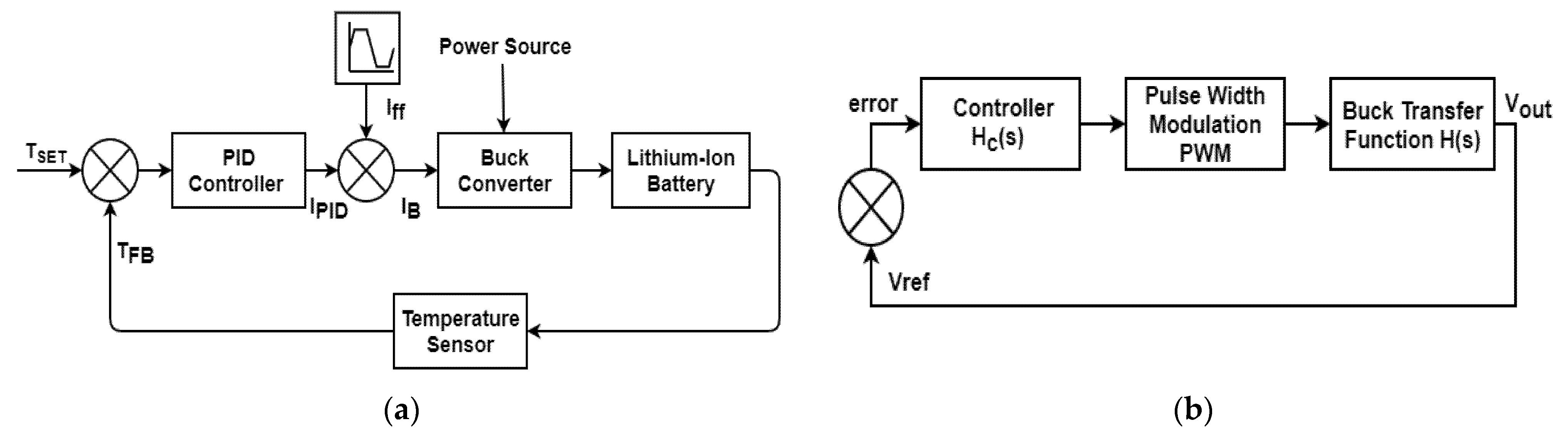
Feedback control of switching regulator consists of three types of controls, i.e., (1) voltage-mode control, (2) current-mode control, and (3) hysteresis control. Each type has its own advantages and disadvantages, and they are selected according to the situation and also by weighing the factors. In this study, we employed voltage-mode control and average current-mode control (VMC, ACM), as these methods are simple with exclusive voltages, control well in a shorter period of time, and it can also resist high noise. Its main disadvantage includes the model complexity and phase compensation circuit. In the voltage mode control method, the block of buck transfer function H(s) depicts the power stage including the inductor, diode, and the capacitor, while the block of controller transfers function Hc(s) shows the controller that is made to compensate the complete control loop, as shown in
Figure 1b. The block of PWM is a part of the buck transfer function block, but it is kept isolated to analyze the results of this block solely. The power stage of the buck converter has the fixed DC input voltage, and it gives the predetermined DC output voltage and duty cycle values in the steady-state condition. This output voltage is sent back, where it is compared with the reference or predefined voltage. This is called the desired voltage. If any divergence from the reference voltage value is observed, then the error term has some nonzero numerical value. Thus, this error value is fed to the controller as an input value. The CT–CV charging method is preferred due to the major reason, i.e., when the charging rate increases or decreases, the battery temperature varies accordingly. This results in the shortening of the lifetime of the battery and increases the charging cycle. Therefore, battery voltage and temperature are kept constant during charging.
Figure 1 depicts the block diagram for the suggested control scheme of the CT–CV charging method, which permits faster charging by increasing the given temperature depending on the battery life cycle.
The resulting duty cycle of PWM in
Figure 1b is the output of the controller that regulates the buck converter in order to provide constant input voltage to the Li-ion cell. The transfer function of buck converter consists of two output filters, i.e., inductor and capacitor, which resonate with each other to produce two poles in the transfer function [
24]. It results in damping, which can be reduced by placing more zeros. The double-pole function has an undamped natural frequency and a resonant peak that depends on the
.
By using the Laplace method and series-parallel combinations, we can calculate the filter transfer function
H(
s) of
Figure 1b.
Second-order polynomial
H(
s) in the standard form is given by
Thus, the double-pole function has some unidentified natural frequency and a vibrating peak reliant on
Q where
and
. Usually, in most industrial applications, capacitors are used in parallel to the output of rectifiers to minimize the ripples and voltage variations [
25]. A built-in MATLAB Simulink model of Lithium-ion temperature-dependent battery was used in this paper. The performance and results of this battery were very close to the real one. During the charging and discharging phase, cell temperature, voltage, and capacity varied accordingly. The specifications of this battery model are given in
Table 2.
Temperature plays a vital role in the mechanical and electrochemical degradation process inside Li-ion batteries. Degradation of the batteries is indicated as a decline in the safety and performance of the Li-ion cells. For example, a higher temperature range can increase the long-run capacity fading and also escalates impedances of cells. For this reason, a closed-loop technique was designed in which the charging profile permits faster charging by ensuring the temperature increase within safe limits. This will result in decreased charging time without affecting the life cycle of Li-ion cells. In the CT–CV method, lithium-ion cell is charged at a greater current than the usual current of 1C, and it also keeps the increase in temperature within safe limits. This closed-loop technique is very efficient, as it verifies the change in the magnitude of the charging current of the Li-ion battery and also increases the charging rate when the defined temperature upsurges. However, the proposed closed-loop charging scheme continuously observed the battery cell temperature and minimized the charging current so as to keep the temperature rising in the nominal range.
A MATLAB function block was used as a temperature sensor. In this block, the limits for the temperature rise were defined in accordance with the battery voltage. This will save the battery from deterioration. The block of the MATLAB function served the purpose of temperature feedback (temperature sensor). The PID controller hunts for the possible solutions in the domain of feed-forward term so that the battery cell temperature can be maintained at the set values. The controller gains are set to very high values if the feed-forward term has not been used in a model. This high gain will immediately converge at the solution. However, if the sensor data are noisy, then higher gain values are not efficient and applicable. To avoid this problem, feed-forward terms were used. The charger operates in the CT mode until it reaches the set voltage limit. After that, it moves to the CV mode where the controller measured values and feed-forward terms are negligible.
3. Proposed Feedback PID Control Scheme
Voltage-mode control is considered to be the most effective control technique [
26]. The output voltage (
Voutput) is calculated and then compared with the set reference (
Vreference). As an input to a controller, the difference (
Verror) between the output voltage and the set reference voltage is used, and the new value of the duty cycle to close the control loop is determined by the output of the controller. In the voltage-mode control method, the controller output and error voltage that is fed back can be calculated by Equation (3).
Thus, the only need for the voltage-mode controller is the output voltage information so that it can terminate the control loop of the PID controller and produces a stable output voltage. Usually, to supply an overall power limitation, some current information is needed [
27]. When the gain of the PID controller is unity, then the output of the controller can be determined by
. It can be seen from
Figure 2 that the output
is sent to the PWM block as an input so that it can generate an efficient duty cycle, which is shown in Equation (4). In case of a small error, the duty cycle is small. Usually, in the case of a PWM comparator and an RC ramp, the output of the prior controller, i.e., control voltage
in the PWM bar, is generally compared with a set RC ramp by means of a comparator. When the
is greater than the set RC ramp value, the comparator has a high output. Thus, in order to achieve a duty cycle of 100%, it is required that the control voltage
should be equal to the highest RC ramp altitude.
For the control loop to be closed, this duty cycle is fed as an input to the buck transfer function block that also consists of the power stage. Thus, it calculates the output voltage. The buck transfer function is shown in Equation (5), while Equations (6)–(8) show the parameters of the transfer function of the buck converter.
The pole-zero frequencies can be calculated by using Equations (9) and (10), respectively.
where
is the parameter of the buck converter that can be calculated by using Equation (11).
The z-domain transfer function of the PID controller is defined by
where
and
,
where
defines the integral gain,
represents the damping ratio,
Ts is the sampling time period, and
is the controller’s natural frequency.
is the parameter that depends on the high-frequency controller gain. The transfer function is calculated by using these equations and the designed PID controller.
It is very important and beneficial to maintain the best voltage regulation and transient responses over a vast range of load current in designing the control loop of the buck converter. Current-mode control is one of the major control methods that is widely used in the topology of most Buck converters [
27,
28]. This technique has proven its vibrant performance and undeniable properties such as protection of short circuits [
29]. Current-mode control has two major types: peak current-mode control and average current-mode control.
The peak current-mode control technique has several disadvantages—namely, it becomes unstable at the duty cycle higher than 0.5. This generates subharmonic vibrations and oscillations in the system. This instability is removed by using a compensating ramp that has a slope equivalent to the downslope of the inductor current. Furthermore, it also makes the system complicated in which buck converters are used along with rectifiers. Therefore, the average current-mode (ACM) control method was used in this paper to govern the current of the battery charger within safe limits.
Figure 2 depicts the detailed circuitry of ACM with buck converter. In the buck converter, the current flowing through the inductor is also the output current, which has vast ripples. These ripples are caused due to ramp-up and ramp-down of the inductor current.
Average current-mode control has two loops similar to the PCM technique. The outer loop of ACM applies the voltage control technique in which error is calculated by comparing reference voltage with output voltage. The inner loop calculates the average inductor current and then compares it with the reference current in order to calculate the error current, which is then processed by the compensator. This produces a signal that is compared with the applied saw-tooth signal at the current comparator inputs. In the current loop, ACM uses a very high-gain op-amp. For optimal performance, the gain bandwidth of the inner loop (current loop) can be adjusted by the compensator. The crossover frequency of ACM is the same as that of PCM, but the gain is very high even at lower frequencies. ACM does not need any slope compensation. The limit is required for the loop gain at the switching frequency for making the system stable. The oscillations produced in the control circuitry are minimized by the oscillator ramp, as it gives the high value of slope compensation. In the case of a single-pole system, the downslope of amplified inductor current should not exceed the slope of the oscillator ramp at the PWM comparator inputs [
30]. This develops the highest crossover frequency (current loop gain). As the control signal is the duty cycle, and the output signal is the output voltage, the transfer function
of the buck converter in the frequency domain can be calculated by using the equations shown below.
where
Transfer function demonstrates that the power stage of the buck converter is a second-order system that has one zero and two poles in the s-domain. The output capacitor C is responsible for generating a zero Sz_ESR, while the LC filter generates the resonant double-pole wo. The power stage of the buck converter is highly dependent on the value of output capacitors.
4. Experimental Setup
The experimental setup used to validate the proposed CT–CV charging technique is shown in
Figure 3. This experiment used a lithium-ion 26,650 cylindrical cell, which is one of the most common formats for several applications. A temperature sensor was used to measure the cell temperature during a charging cycle. A polyester film tape was used to affix the temperature sensor to the middle of the battery cell. A two-terminal power supply was used at the input. Then, a rectifier was connected to convert the AC voltage to DC voltage.
To meet the strict output voltage regulation requirement, a large inductor and output capacitor were connected. A buck converter was connected to the rectifier to step down the DC voltage. The positive terminal of the cell was connected to the power supply through a power MOSFET, while the negative terminal was connected to the ground of the power supply via a low-value shunt resistor. The Arduino Pro Mini compatible board U2 contains an ATmega 328 P microcontroller that runs at 16 MHz and served as the device’s main processing unit. It controlled and monitored the cell temperature, state of charge, current, and voltage continuously. The charging current was controlled using pulse width modulation (PWM), in which the Arduino switched the MOSFET on and off at a frequency of 31.2 kHz. The charging current was regulated by changing the PWM duty cycle, which is the ratio of MOSFET on and off time. The current was programmed once every 3 s in CT mode; setting a maximum voltage limit guaranteed that CV mode would be initiated when 4.2 V was achieved. The cell terminal voltages were measured using two different ADC channels on the Arduino. V and I were constantly monitored by the Arduino, which changed the PWM duty cycle to achieve the optimal constant voltage control. Furthermore, reading the battery voltage V and comparing it with a set of values contained in a lookup table created the state of charge SoC. The Arduino’s RS232 serial port can be used to access the charger’s command-line interface (CLI). The simplest way to connect to the CLI is to use an FTDI USB-to-serial converter and open the serial display of the Arduino IDE when connected to the charger. The MATLAB Simulink was used for the simulations. The initial temperature of the reference battery was set to 20 °C. The voltage and current of battery A were controlled by applying voltage-mode control and average current-mode control methods.
5. Results and Discussion
This section presents the outcomes of the proposed CT–CV technique in comparison with reference battery B and the regular CC–CV method. The reference battery is the built-in model of MATLAB Simulink, which was used for simulation purposes only. For the experimental setup, the lithium-ion cell 26,650 having the specification of maximum voltage 4.2 V and capacity 5 Ah was used. No technique was applied to the reference battery in order to compare the results with our proposed charging scheme.
Figure 4 shows the results of the voltage-mode control technique applied to battery A, along with the CT–CV method and reference battery B. In the CT–CV method, the current does not exceed the limits and is controlled well under the limit of 10 A during the charging phase, as shown in
Figure 4a. This will increase the life span of the battery and protect it from aging. Thus, the application of CT–CV, along with voltage-mode control technique, ensures higher stability of the feedback loop. It can be seen from
Figure 4b that the state-of-charge of the proposed method is 26%, while the SOC of the reference battery hardly charges to 6% when its temperature rises to 26 degrees. This means that the proposed method is achieving 23% faster charging than reference battery B. The battery temperature in the proposed model is also maintained in the safe limits, i.e., it rises to a maximum of 36 degrees during the charging of the battery, as evident in
Figure 4c. Most cell depletion processes can also be held under control by not allowing the cell temperature to rise above a certain set point, thereby increasing its life cycle.
Moreover, the average current-mode control method was applied, along with CT–CV in the proposed model, to check the battery cell behavior separately. The designed controller regulates the current to the average of 12 A, as depicted in
Figure 5a. The proposed method regulates the charging current in accordance with the thermal environment. Thus, it will increase the life cycle of the battery. It is shown in
Figure 5b that the SOC of the proposed model is 30%, while the SOC of the reference battery reaches up to 15% during the charging cycle. This means the lithium-ion battery of the proposed model is charging 50% faster, as compared with the reference battery. Meanwhile, the temperature is maintained within safe limits. The battery temperature of the proposed model rises to a maximum of 38 °C, whereas the reference battery temperature reaches 30 °C, as shown in
Figure 5c. In order to save the life span of a Li-ion battery, its charge and discharge must not exceed 45 °C and 60 °C. Therefore, the temperature should not be too high or too low for charging Li-ion batteries, as both are not permissible. High temperature reduces battery life, while charging at very low temperatures will increase the internal resistance of the battery and also decrease its capacity. Due to the complex structure and slow computational power of MATLAB, a 100% profile of SOC of Li-ion cell was not observed in both controlling methods. The state of charge was monitored up to 30% in voltage-mode control and average current-mode control methods.
The results of the experimental setup are shown in
Figure 6. The applied CT–CV charging method adjusts the cell’s current in accordance with the thermal environment. It can be seen that the battery’s current and voltage increase from 0.2 A to 2.25 A and 2 V to 4.1 V as it charges. The initial temperature of the battery cell is 18 °C, which increases to 35.6 °C during a charging cycle. This temperature range is safe for Li-ion batteries. The state of charge reaches 100% during a charging cycle, which means that the proposed CT–CV method fully charges the cell in 40 min. To validate the efficiency of the proposed method, the SOC of the CT–CV method was compared with the SOC of the reference battery. The reference battery was the same Li-ion cell 26650, but no technique was applied to it.
Figure 6b shows that CT–CV charges the cell completely in 40 min, whereas the reference battery is charged up to 89% with the same amount of time. In the case of 80% charging the cell, the CT–CV charging is 20% faster than reference battery B.
Table 3 compares the findings of this study to those of other charging methods available in the literature. The experiment was repeated on the same cell with the CC–CV method. It can be seen from
Figure 6c,d that the CT–CV method fully charges the cell in 40 min with the permissible temperature rise of 36 °C, while the CC–CV method charges in 50 min with a temperature increase of 41 °C. In many applications, the battery cell is only charged up to 80% to increase the life span of the battery; in addition, there is not enough time to fully charge the cell. In these cases, CT–CV would take 30 min to charge, while CC–CV charges in 40 min. Hence, 25% faster charging is achieved. The results obtained from this paper can be compared with other charging methods in the literature. The charging setup for SRC charging and pulse-current charging is much more complex, as it requires high bandwidth current controllers.
The demonstrated results show that by keeping the battery cell temperature within the limits of a specific value, the cell degradation process can be successfully controlled, thus extending the period of the battery’s exploitation. However, as seen above, there are a few drawbacks that necessitate further studies of the benefits of the proposed charging method. In order to achieve smoother charging profiles, different temperature sensors can be used with the proposed method. The number of temperature sensors needed for proposed charging increases with the increase in the number of cells in a battery. Most BMSs effectively offer various temperature sensing that can be used with the proposed charging strategy. Efficient thermal models and temperature estimators can be used to substitute the sensors in situations where temperature sensors are not accessible [
31,
32,
33]. This possibly allows the proposed charging strategy to be the best option for multicell battery packs as well.


 ,
, 


