
LIHL: Design of a Novel Loop Interlocked Hardened Latch

1
College of Computer and Engineering, Anhui University of Science and Technology, Huainan 232001, China
2
Anhui Huainan Pingwei Power Generation Company Ltd., Huainan 232001, China
3
School of Microelectronics, Hefei University of Technology, Hefei 230009, China
*
Author to whom correspondence should be addressed.
Electronics 2021, 10(17), 2090; https://doi.org/10.3390/electronics10172090
Submission received: 15 July 2021
/
Revised: 24 August 2021
/
Accepted: 26 August 2021
/
Published: 28 August 2021
(This article belongs to the Section Semiconductor Devices)
Abstract
:A single event causing a double-node upset is likely to occur in nanometric complementary metal-oxide-semiconductor (CMOS). Contemporary hardened latch designs are insufficient in meeting high reliability, low power consumption, and low delay. This paper presents a novel soft error hardened latch, known as a loop interlocked hardened latch (LIHL). This latch consists of four modified cross-coupled elements, based on dual interlocked storage cell (DICE) latch. The use of these elements hardens the proposed LIHL to soft errors. The simulation results showed that the LIHL has single-event double upset (SEDU) self-recoverability and single-event transient (SET) pulse filterability. This latch also reduces power dissipation and propagation delay, compared to other SEDU or SET-tolerant latches.
1. Introduction
A soft error is generated when a particle strikes a sensitive node within a memory element—such as a latch or flip-flop—and changes its logic values [1,2,3]. With the trend of decreasing technology node, the charge required to define the logic states of memory elements has become smaller, making them more susceptible to soft-errors induced by striking particles [4,5,6].
The main types of soft errors are single-event upset (SEU), single-event double-upset (SEDU), and single-event transient (SET). Radiation effect on circuits is more likely to occur with technology scaling [7]. Scaling increases packing densities, as well as decreases nodal charge, device spacing, and the critical charge required to upset logic values [8]. Therefore, a small amount of injected charge due to striking particles may lead to a single-event upset (SEU) and charge sharing. It may also cause internal node pairs to change state, resulting in SEDU [9,10,11]. Researchers have demonstrated that significant radiation could lead to an increase in soft error rates resulting from SEDU [12,13].
A particle striking a logic gate on a combinational circuit may produce a current pulse referred to as a SET. As the pulse propagates through the logic gates to a storage cell, a transient fault is produced. Researchers recently proposed a range of hardened schemes to effectively improve SEU tolerance. These schemes made use of dual-mode interlocks [14,15,16], guard doors [17,18,19], redundancy [20,21,22], and feedback delays [23,24,25,26]. Pulse filters can be used to filter out SET pulses [25,26,27,28]. A range of hardened schemes, based on classical Dual Interlocked Storage Cell (DICE) and tolerant SEDU, were also proposed [29,30,31,32]. SEU tolerance can also be improved through a range of layout solutions such as well isolation, increased node spacing, and redundancy. Hardened schemes increase circuit complexity, though they are better able to tolerate SEDU [13,14,33,34,35,36,37]. A few latch designs are cost-effective while increasing SEU, SEDU, and SET tolerance.
This paper proposed a novel soft error hardened latch design. The proposed design used four improved cross-coupled elements based on DICE. This design is capable of self-recovering from SEU, tolerating SEDU, and filtering SET pulses. Simulation results showed SEDU and SET do not impact this latch. Section 2 of this paper reviews previous SEU and/or SEDU radiation hardened latch designs; Section 3 contains the proposed latch design and simulation results; and Section 4 presents conclusions.
2. Previous Works
This section reviews the typical examples of SEU and/or SEDU-tolerant latch designs such as DICE [16], FERST [27], LCHR [28], DNCS [31], HRCE [36], and LCDNUT [37].
DICE is a robust soft-error–resilient design that utilizes two interlocked latches. The interlocked structure holds state through interactions to recover single-node upsets caused by SEUs [16]. The schematic diagram is shown in Figure 1.
The latch pairs store logically complementary values. In the event of a single or adjacent node upset due to striking particles, the storage cell can recover from the upset node because of the feedback loop. However, when a strike affects non-adjacent nodes, the cell is upset due to structural limitations. A simplified double interlocking structure is shown in Figure 2.
In the simplified structure diagram, D (see Figure 1) inputs logic signals to X0 and X2 through the transmission gate, and node X1 connects an inverter to the output Q. Four nodes are connected through cross-coupled elements to form a dual interlocked storage structure. If input D (see Figure 1) is inverted due to an SET, X1 and X3 are also inverted, causing an output error. This means DICE is not immune to the non-adjacent node upsets, i.e., this structure cannot tolerate SEDU completely.
Figure 3 shows the schematic of the FERST [27]. The schematic uses the inverter and the two-input C-element to form the interlocked feedback loop, in which the C-element close to the output Q is used as a voter. This structure can tolerate SEU. When the N1 (N2) node is inverted, it can be recovered by N3 (N4) through the feedback loop; when the N3 (N4) node is inverted, the value of N1 (N2) changes through the feedback loop at the same time. This structure can tolerate SEU but cannot self-recover if the node N3 or N4 flipped.
Figure 4 shows the schematic of the LCHR [28]. This schematic uses double modular redundancy technology to replicate the non-radiation hardened circuit and connect it to a multi-input C-element as a voter. This structure can also tolerate SEU. However, when any node in the circuit is inverted, it cannot self-recover to the original value. At the same time, this structure cannot tolerate SEDU and is sensitive to the high-impedance state.
Figure 5 shows the schematic of the DNCS [31]. This schematic uses six two-input C-elements to form a feedback loop, which is connected to a three-input C-element for voting output. When the two-input nodes of a C-element are both flipped, these two nodes cannot be restored to the correct value in this case. This structure can fully tolerate SEDU; however, the structure cannot self-recover.
Figure 6 shows the schematic of the HRCE [36]. This latch uses multi-input C-elements to form a feedback loop to store data, and uses a transmission gate to connect input and output to build a fast path to reduce delay. Due to the feedback loop, the structure can fully tolerate SEDU and self-recover, but the area of this structure is too large.
Figure 7 shows the schematic of the LCDNUT [37]. This latch is mainly constructed from a storage module in the left part and a clock-gating based error-interceptive four-input C-element in the right part. This structure also can tolerate SEDU but cannot self-recover and is sensitive to the high-impedance state.
The above schematics can tolerate SEU and/or SEDU. Some schematics can restore the flipped nodes to ensure that the output value is not affected. Most schematics use C-element as a voter since C-element outputs high impedance state when its inputs are different because the characteristics of C-element can prevent the propagation of errors. However, the C-element holds the high-impedance state for a long time, which will cause leakage current and will flip the output, thus generating the wrong logic value.
3. Proposed Design and Simulation Results
3.1. Proposed Design
The schematic of the proposed soft error hardened latch is presented in Figure 8. A charging structure is included. This structure consists of MP3 connected to GND, and MN3 connected to VDD. The charging structure can be used to filter SET pulse and delay SEDU, enabling fault tolerance. TG1 and TG2 are transmission gates controlled by clock (CLK) and its inverted signal (CLKB). X1 was connected to output Q through an inverter, and the loop interlocked structure comprises four cross-coupled elements (C1, C2, C3, and C4).
When CLK is high and CLKB is low, the transmission gates TG1 and TG2 are turned on, and the latch works in the transparent mode. For instance, assuming the input signal D is 0, X0 and X2 are controlled by the transmission gate, and both store the 0states. When node X0 is logic 0, MP1 and MP2 are both turned on, while MP3 is turned off. Hence, X1 is logic 1, and MN1 and MN2 are turned on, while MN3 is turned off. Through the cross-coupled structure, a self-latching structure C1 comprises X0 and X1, which can store logic values. Similarly, a self-latching structure C3 comprises X2 and X3. Since X1 is 1 and X2 is 0, the cross-coupled structure C2, composed of X1 and X2, cannot be turned on. When the input signal D is 1, C4 is turned on due to X0 being 1 and X3 being 0. Similarly, C2 is also in a self-latching state, while C1 and C3 are blocking. When the latch outputs data, the logic values are output correctly, as shown in Figure 9.
The simulated LIHL was carried out with HSPICE tool using a 32 nm PTM [38]. The supply voltage was 0.9 V, the temperature was 25 °C, and the clock frequency was 0.5 GHz.
3.2. Single Node Upsets Analysis
When CLK is low and CLKB is high, the transmission gates are off, and the latch switches to hold mode. Assuming nodes X0, X1, X2, and X3 are 0, 1, 0, and 1, respectively, SEU injections are performed, and the result is shown in Figure 10.
When X0 was inverted, its logical value changed from 0 to 1. MP1, MP2, and the cross-coupled structure C1 were then turned off, and MP3 was turned on. An n-type metal-oxide-semiconductor (NMOS) is imperfect at passing 1, while a p-type metal-oxide-semiconductor (PMOS) degrades 0. Since the PMOS was connected to GND and the NMOS to VDD, the PMOS weakened the logic signal from the MP3 path, and the logic was recovered. When TG1 and TG2 were turned on, MP3 and MN3 were also turned on, and the cross-coupled element C4 was in a charging state. When the value of X0 was changed, MN1 and MN2 were turned on, while MP3 was turned off. Due to the charge deposited during charging, if node X3 was to be inverted, node B must first be discharged, and X0 recovers the logic value through C1. This causes MN1 and MN2 to be turned off again. Similarly, when X1, X2, and X3 were inverted, the latch state was recovered through the circuit feedback.
When the nodes X0, X1, X2, and X3 were 1, 0, 1, and 0, respectively, the cross-coupled elements C1 and C3 were turned off. Node A was discharged to GND through MP3 in C1 and Node B was charged to VDD through MN3 in C1; When X0 was inverted, MN3 was turned off, MP1 and MP2 were turned on, and node A was charged. X0 was recovered from X3. X1, X2, X3, and X0 were similar to the state of upset to recovery.
3.3. Double Node Upsets and SET Analysis
In the hold state, it is assumed that the logical values of X0, X1, X2, and X3 are 0, 1, 0, and 1, respectively. SEDU injection was performed for X0 and X1, so that the values of X0 and X1 changed to 1 and 0, respectively. When C1 is turned off, C2 and C4 were in a discharge state, and the charge caused by striking particles gradually decreased. Finally, the feedback of X0 through C1 was recovered, while C4 and C2 were not affected by the charging effect. X2 and X3 upsets were the same. Its fault tolerance principle is similar to the DICE structure. SEDU injection was performed on X0 and X2. Due to the delay of X1 and X3 charging, the upsets of X0 and X2 were equivalent to independent single-event upsets. The logical values of X0 and X2 were both changed from 0 to 1. For structures that cannot be SET hardened, a logical storage error occurs. Elements C2 and C4 had to be discharged for a period of time due to the pre-charge of node B. The logic values of X0 and X2 were recovered through the feedback loops of C1 and C3. The result is shown in Figure 11.
For the logic error caused by an SET, the input signal was inverted. This error first upset X0 and X2, and then the output value had a transient upset. As shown in Figure 12 and Figure 13, when D was 0 and inverted by the transient pulse, it propagated to X0 and X2. If it was propagated to the output, node A and node B must have been discharged first. Similarly, when D was 1, it was affected by transient pulse. If this affects the output, the structure must discharge node A of the cross-coupled element C1. C1 was recovered because X0 recovered through X3 in a short time. The simulation result was similar to X0 and X2 upsets. Similarly, the upset of the node pairs <X1, X3> was similar to <X0, X2>, the upset of the node pairs <X0, X3>, <X1, X2> and <X2, X3> were similar to <X0, X1> The peak value of the fault injection was 0.9 V, the rise time was 0.02 ns, and the fall time was 0.1 ns.
3.4. Comparisons
For fair comparisons, the proposed latch design and typical SEU/SEDU hardened latch designs, namely the DICE [16], FERST [27], DNCS [31], LCHR [28], HRCE [36], and LCDNUT [37] were simulated in the same technology node using the 32 nm PTM in [38]. The supply voltage VDD was set to 0.9 V, the temperature was set to 25 °C, and the clock frequency was set to 0.5 GHz. The transistor sizes in these latch designs were set as follows: as for all PMOS, the transistors had W/L = 64/32 nm, while the NMOS transistors had W/L = 32/32 nm.
Table 1 compares the tolerance ability of LIHL against other classical designs. Unlike the other designs, the proposed LIHL latch can tolerate soft errors caused by SEU, SEDU, and SET.
In order to prove that the proposed LIHL design can operate under different working voltages, an HSPICE simulation was performed on the design under operating voltages of 0.7–1.1 V. The simulation result is presented in Figure 14.
The delay, power consumption, and power delay product (PDP) of various latch designs were compared. Delay means D to Q transmission delay, i.e., the average of rise and fall delays of D to Q, and power consumption means the average power consumption of the latch in book [39]. Referring to Figure 15, with exception of the DICE latch, the proposed LIHL design has the advantage of a significantly lower delay.
Figure 16 shows that, with the exception of LCHR and DICE, the proposed LIHL design has lower power consumption, compared to others, especially those with SEDU- or SET-tolerant capacity.
Figure 17 compares the PDP of the proposed LIHL design against those of other latch designs. The LIHL PDP is reasonably low, indicating that the design can tolerate soft errors while maintaining low power consumption and propagation delay.
Figure 18 and Figure 19 show the experimental results of the effect of temperature changes on the delay and power of the latch. The normal temperature is set to 25 °C, and the temperature varies from −25 °C to 55 °C. It can be seen from the experimental results that the HRCE latch and the DNCS latch are more sensitive to temperature changes, and the power consumption and delay fluctuate greatly; meanwhile, DICE, LCDNUT, and the proposed latch are not sensitive to temperature, and the power consumption and delay fluctuation are more stable.
Figure 20 and Figure 21 show the effect of the threshold voltage (Vth) on the delay and power of the latches. The Vth of the NMOS transistor is set from −0.5088 to −0.5888. Through the experimental result, it can be seen that the delay of all latch is less sensitive to the Vth changes, and basically maintains a stable state; the HRCE and FERST latches are highly sensitive to the Vth on power consumption. The power consumption and delay of the latch structure proposed in this paper are relatively stable, and the fluctuation is slight.
The power consumption, delay, and PDP of the proposed LIHL design can be compared against others using this formula:
Δ = (proposed latch-compared latch)/(compared latch),
Table 2 shows the value of power, delay, and PDP of the LIHL design and other latch designs; Table 3 shows the value of area and ∆area; and Figure 22 shows that ∆power, ∆delay and ∆PDP of various latch designs compared to the proposed latch. ∆ means the percentage change of the compared latch and the latch proposed in this paper. In Figure 22 and Table 3, negative values denote that the proposed latch has advantages. From Figure 22, DICE latch and LCDUNT latch have lower power, delay and PDP, but DICE latch is not completely SEDU-tolerant and from Table 3, LCDUNT latch has a larger area than the proposed latch. It also can be seen that LIHL has a lower area compared with other SEDU-tolerant and/or SEDU-recovered latches. In the area-critical field, the LIHL latch is competitive.
4. Conclusions
Aiming for soft errors tolerance, this paper proposed a novel LIHL. Simulation results showed that the design could effectively tolerate soft errors. Compared with DICE, which is only capable of SEU tolerance, LIHL has the capacity for SEU, SEDU, and SET tolerance. Compared with the DNCS and HRCE designs, LIHL power consumption is reduced by 86.31% and 91.07%, respectively. Compared with the LCDNUT designs, LIHL power consumption is increased by 82% and the delay is similar, but the LIHL area is reduced by 28.53%. Compared to existing radiation hardened latches, LIHL has better performance with lower area, power consumption, and delay. With CMOS technology aggressively scaling down, integrated circuits are becoming vulnerable to radiation-induced errors. The probability of the multiple node upset is gradually increasing. Due to the better performance and lower overhead of this structure, multiple-node upset-tolerant latches can be designed with this structure in future work [40].
Author Contributions
Conceptualization, H.X. and X.L.; software, X.L.; validation, G.Y. and Z.H.; formal analysis, Z.H.; writing—original draft preparation, H.X.; writing—review and editing, H.L.; supervision, H.L.; project administration, Z.H.; funding acquisition, H.L. All authors have read and agreed to the published version of the manuscript.
Funding
This work was supported in part by the Special Fund for Research on National Major Research Instruments of China under Grant 62027815, the National Natural Science Foundation of China under Grant 61834006, 61674048, 61874156 and 61404001.
Conflicts of Interest
The authors declare no conflict of interest.
References
- Gadlage, M.J.; Roach, A.H.; Duncan, A.R.; Williams, A.M.; Bossev, D.P.; Kay, M.J. Soft errors induced by high energy electrons. IEEE Trans. Device Mater. Reliab. 2017, 17, 157–162. [Google Scholar] [CrossRef]
- Zhang, H.; Jiang, H.; Assis, T.R.; Ball, D.R.; Narasimham, B.; Anvar, A.; Massengill, L.W.; Bhuva, B.L. Angular Effects of Heavy-Ion Strikes on Single-Event Upset Response of Flip-Flop Designs in 16-nm Bulk FinFET Technology. IEEE Trans. Nucl. Sci. 2017, 64, 491–496. [Google Scholar] [CrossRef]
- Zhang, H.; Jiang, H.; Assis, T.R.; Mahatme, N.N.; Narasimham, B.; Massengill, L.W.; Bhuva, B.L.; Wen, S.; Wong, R. Effects of Threshold Voltage Variations on Single-Event Upset Response of Sequential Circuits at Advanced Technology Nodes. IEEE Trans. Nucl. Sci. 2017, 64, 457–463. [Google Scholar] [CrossRef]
- Gill, B.; Seifert, N.; Zia, V. Comparison of alpha particle and neutron-induced combinational and sequential logic error rates at the 32 nm technology node. In Proceedings of the IEEE International Reliability Physics Symposium, Montreal, QC, Canada, 26–30 April 2009; pp. 199–205. [Google Scholar] [CrossRef]
- Anjan, S.; Maryam, B. Robust soft error tolerant CMOS latch configurations. IEEE Trans. Comput. 2016, 65, 2820–2834. [Google Scholar] [CrossRef]
- Gill, B.S.; Papachristou, C.; Wolff, F.G.; Seifert, N. Node sensitivity analysis for soft errors in CMOS logic. In Proceedings of the IEEE International Conference on Test, Austin, TX, USA, 8–8 November 2005; pp. 1–9. [Google Scholar] [CrossRef]
- Yan, A.; Yang, K.; Huang, Z.; Zhang, J.; Cui, J.; Fang, X.; Yi, M.; Wen, X. A double-node-upset self-recoverable latch design for high performance and low power application. IEEE Trans. Circuits Syst. II Express Briefs 2019, 66, 287–291. [Google Scholar] [CrossRef]
- Jagannathan, S.; Loveless, T.D.; Bhuva, B.L.; Wen, S.; Wong, R.; Sachdev, M.; Rennie, D.; Massengill, L.W. Single-event tolerant flip-flop design in 40nm bulk CMOS technology. IEEE Trans. Nucl. Sci. 2011, 58, 3033–3037. [Google Scholar] [CrossRef]
- Baumann, R.C. Radiation-induced soft errors in advanced semiconductor technologies. IEEE Trans. Device Mater. Reliab. 2005, 5, 305–316. [Google Scholar] [CrossRef]
- Chandra, V.; Aitken, R. Impact of voltage scaling on nanoscale SRAM reliability. In Proceedings of the Design, Automation & Test in Europe Conference & Exhibition, Nice, France, 20–24 April 2009; pp. 387–392. [Google Scholar] [CrossRef]
- Rajaei, R.; Asgari, B.; Tabandeh, M.; Fazeli, M. Design of robust SRAM cells against single-event multiple effects for nanometer technologies. IEEE Trans. Device Mater. Reliab. 2015, 15, 429–436. [Google Scholar] [CrossRef]
- Black, J.; Dodd, P.; Warren, K. Physics of multiple node charge collection and impacts on single-event characterization and soft error rate prediction. IEEE Trans. Nucl. Sci. 2013, 60, 1836–1851. [Google Scholar] [CrossRef]
- Yamamoto, Y.; Namba, K. Construction of Latch Design with Complete Double Node Upset Tolerant Capability Using C-Element. In Proceedings of the International Symposium on Defect and Fault Tolerance in VLSI and Nanotechnology Systems, Chicago, IL, USA, 8–10 October 2018; pp. 8–10. [Google Scholar] [CrossRef]
- Guo, J.; Zhu, L.; Liu, W.; Huang, H.; Liu, S.; Wang, T.; Xiao, L.; Mao, Z. Novel radiation-hardened-by-design (RHBD) 12T memory cell for aerospace applications in nanoscale CMOS technology. IEEE Trans. Very Large Scale Integr. Syst. 2017, 25, 1593–1600. [Google Scholar] [CrossRef]
- Huang, Z.; Liang, H.; Hellebrand, S. A high performance SEU tolerant latch. J. Electron. Test. 2015, 31, 349–359. [Google Scholar] [CrossRef]
- Calin, T.; Nicolaidis, M.; Velazco, R. Upset hardened memory design for submicron CMOS technology. IEEE Trans. Nucl. Sci. 1996, 43, 2874–2878. [Google Scholar] [CrossRef]
- Alioto, M.; Consoli, E.; Palumbo, G. Variations in nanometer CMOS flip-flops: Part I-impact of process variations on timing. IEEE Trans. Circuits Syst. I Regul. Pap. 2015, 62, 2035–2043. [Google Scholar] [CrossRef]
- Omana, M.; Rossi, D.; Metra, C. High-performance robust latches. IEEE Trans. Comput. 2010, 59, 1455–1465. [Google Scholar] [CrossRef]
- She, X.; Li, N.; Tong, J. SEU tolerant latch based on error detection. IEEE Trans. Nucl. Sci. 2012, 59, 211–214. [Google Scholar] [CrossRef]
- Mitra, S.; Zhang, M.; Seifert, N.; Mak, T.; Kim, K.S. Built-in soft error resilience for robust system design. In Proceedings of the IEEE International Conference on Integrated Circuit Design and Technology, Austin, TX, USA, 30 May–1 June 2007; pp. 1–6. [Google Scholar] [CrossRef]
- She, X.; Mcelvain, K. Time multiplexed triple modular redundancy for single event upset mitigation. IEEE Trans. Nucl. Sci. 2009, 56, 2443–2448. [Google Scholar] [CrossRef]
- Yan, A.; Liang, H.; Huang, Z.; Jiang, C.; Yi, M. A self-recoverable, frequency-aware and cost-effective robust latch design for nanoscale CMOS technology. IEICE Trans. Electronic 2015, 98, 1171–1178. [Google Scholar] [CrossRef]
- Shah, J.; Nairn, D.; Sachdev, M. A 32 kb macro with 8T soft error robust, SRAM cell in 65nm CMOS. IEEE Trans. Nucl. Sci. 2015, 62, 1367–1374. [Google Scholar] [CrossRef]
- Wang, H.; Chen, L.; Liu, R.; Li, Y.; Kauppila, J.S.; Bhuva, B.L.; Lilja, K.; Wen, S.; Wong, R.; Fung, R.; et al. An Area Efficient Stacked Latch Design Tolerant to SEU in 28 nm FDSOI Technology. IEEE Trans. Nucl. Sci. 2016, 63, 3003–3009. [Google Scholar] [CrossRef]
- Alidash, H.K.; Oklobdzija, V. Low-power soft error hardened latch. J. Low Power Electron. 2010, 6, 218–226. [Google Scholar] [CrossRef]
- Rajaei, R.; Tabandeh, M.; Fazeli, M. Low cost soft error hardened latch designs for nano-scale CMOS technology in presence of process variation. Microelectron. Reliab. 2013, 53, 912–924. [Google Scholar] [CrossRef]
- Fazeli, M.; Miremadi, S.G.; Ejlali, A.; Patooghy, A. Low energy single event upset/single event transient-tolerant latch for deep submicron technologies. IET Comput. Digit. Tech. 2009, 3, 289–303. [Google Scholar] [CrossRef]
- Qi, C.; Xiao, L.; Guo, J.; Wang, T. Low cost and highly reliable radiation hardened latch design in 65 nm CMOS technology. Microelectron. Reliab. 2015, 55, 863–872. [Google Scholar] [CrossRef]
- Eftaxiopoulos, N.; Axelos, N.; Zervakis, G.; Tsoumanis, K.; Pekmestzi, K. Delta DICE: A Double Node Upset resilient latch. In Proceedings of the IEEE International Midwest Symposium on Circuits and Systems, Fort Collins, CO, USA, 2–5 August 2015; pp. 2–5. [Google Scholar] [CrossRef]
- Eftaxiopoulos, N.; Axelos, N.; Pekmestzi, K. DONUT: A double node upset tolerant latch. In Proceedings of the IEEE Computer Society Annual Symposium on VLSI, Montpellier, France, 8–10 July 2015; pp. 509–514. [Google Scholar] [CrossRef]
- Katsarou, K.; Tsiatouhas, Y. Soft error interception latch: Double node charge sharing SEU tolerant design. Electron. Lett. 2015, 51, 330–332. [Google Scholar] [CrossRef]
- Xu, H.; Zeng, Y. Circuit and layout combination technique to enhance multiple nodes upset tolerance in latches. IEICE Electron. Express 2015, 12, 1–7. [Google Scholar] [CrossRef] [Green Version]
- Li, Y.; Wang, H.; Yao, S.; Yan, X.; Gao, Z.; Xu, J. Double node upsets hardened latch circuits. J. Electron. Test. 2015, 31, 537–548. [Google Scholar] [CrossRef]
- Eftaxiopoulos, N.; Axelos, N.; Pekmestzi, K. DIRT latch: A novel low cost double node upset tolerant latch. Microelectron. Reliab. 2017, 68, 57–68. [Google Scholar] [CrossRef]
- Wei, W.; Namba, K.; Kim, Y.; Lombardi, F. A novel scheme for tolerating single event/multiple bit upsets (SEU/MBU) in non-volatile memories. IEEE Trans. Comput. 2016, 65, 781–790. [Google Scholar] [CrossRef]
- Li, H.; Xiao, L.; Li, J. High robust and cost effective double node upset tolerant latch design for nanoscale CMOS technology. Microelectron. Reliab. 2019, 93, 89–97. [Google Scholar] [CrossRef]
- Yan, A.; Lai, C.; Zhang, Y.; Cui, J.; Huang, Y.; Song, J.; Guo, J.; Weng, X. Novel Low Cost, Double-and-Triple-Node-Upset-Tolerant Latch Designs for Nano-scale CMOS. IEEE Trans. Emerg. Top. Comput. 2021, 9, 520–533. [Google Scholar] [CrossRef] [Green Version]
- Predictive Technology Model. Available online: http://ptm.asu.edu (accessed on 22 February 2006).
- Weste, N.H.E.; Harris, D.M. CMOS VLSI Design: A Circuits and Systems Perspective, 4th ed.; Addison-Wesley: Boston, MA, USA, 2011; p. 318. [Google Scholar]
- Yan, A.; Ling, Y.; Cui, J.; Chen, Z.; Huang, Z.; Song, J.; Girard, P.; Wen, X. Graduate School of Computer Science and Systems Engineering, Kyushu Institute of Technology, Fukuoka, Japan Quadruple Cross-Coupled Dual-Interlocked-Storage-Cells-Based Multiple-Node-Upset- Tolerant Latch Designs. IEEE Trans. Circuits Syst. I Regul. Pap. 2020, 67, 879–890. [Google Scholar] [CrossRef]
Figure 1.
DICE (Dual Interlocked Storage Cell) schematic.

Figure 2.
Simplified structure diagram of DICE.

Figure 3.
FERST schematic.
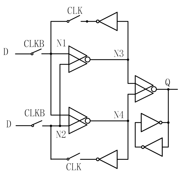
Figure 4.
LCHR schematic.
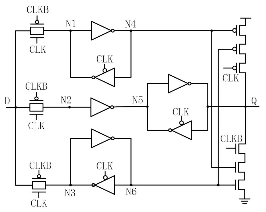
Figure 5.
DNCS schematic.
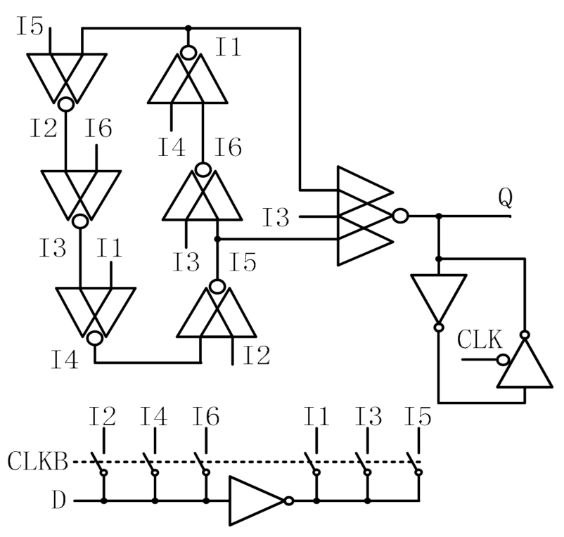
Figure 6.
HRCE schematic.

Figure 7.
LCDNUT schematic.
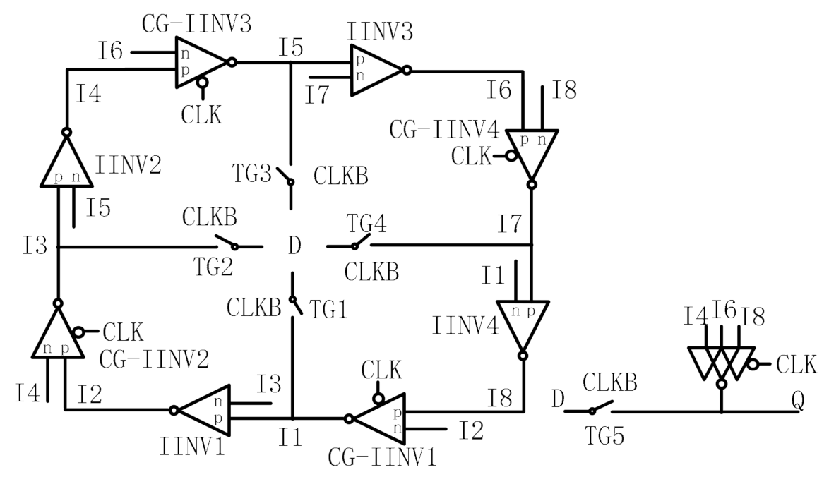
Figure 8.
Proposed novel loop interlocked hardened latch (LIHL).
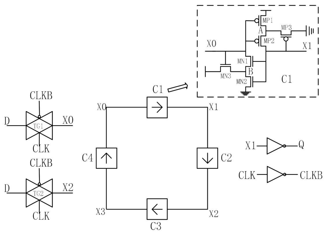
Figure 9.
Simulation result under normal working condition.

Figure 10.
Simulation result during SEU injections.
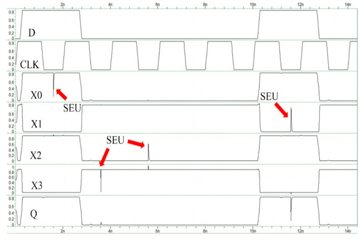
Figure 11.
Simulation result during (X0, X1) SEDU injection.
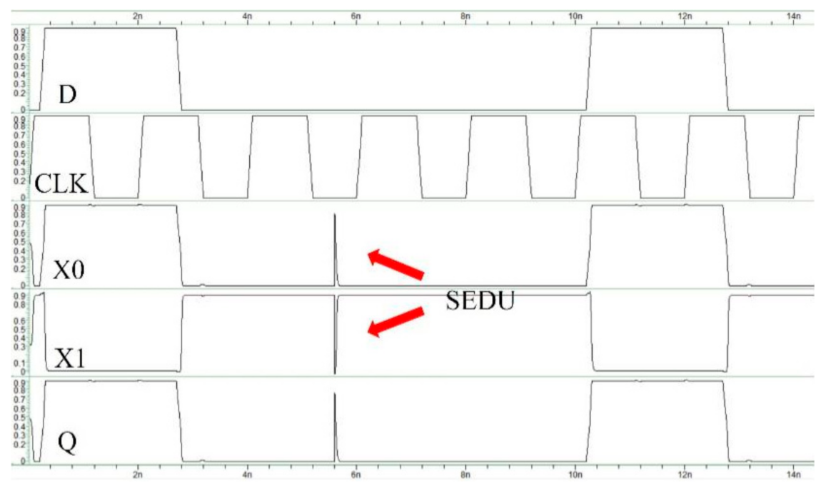
Figure 12.
Simulation result during SET injection.

Figure 13.
Simulation result during SEDU injection.

Figure 14.
Design simulation under working voltages of 0.7–1.1 V.

Figure 15.
Delay comparison of various latch designs under different voltages.
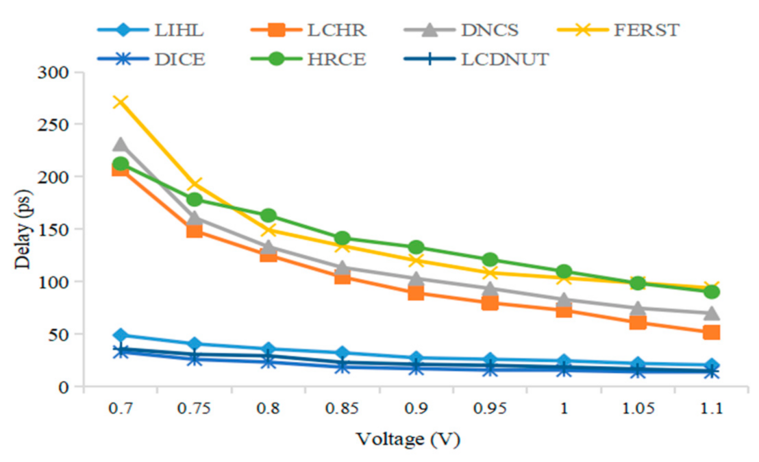
Figure 16.
Power consumption of various latch designs under different voltages.
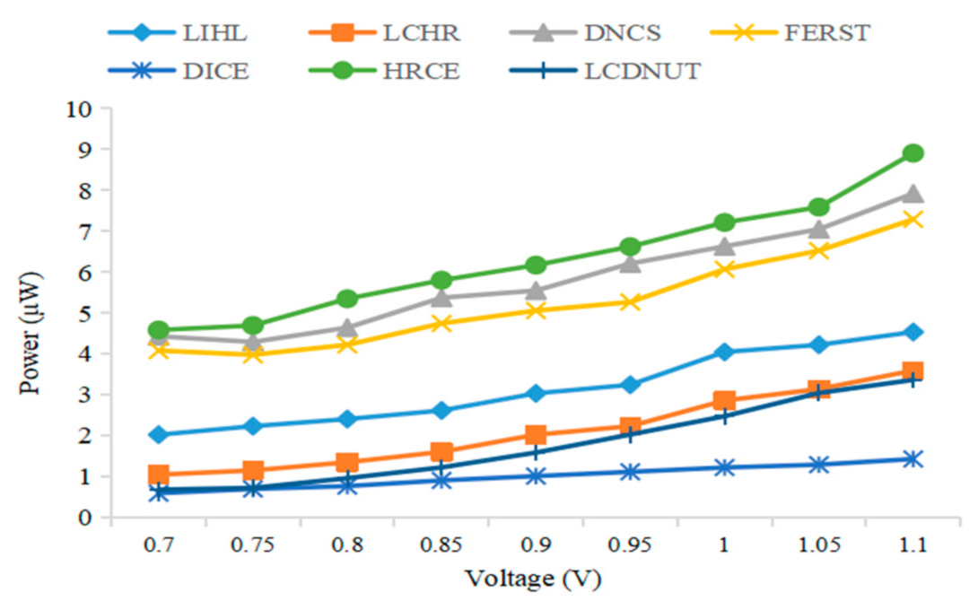
Figure 17.
PDP of various latch designs under different voltages.

Figure 18.
Delay comparison of various latch designs under different temperatures.
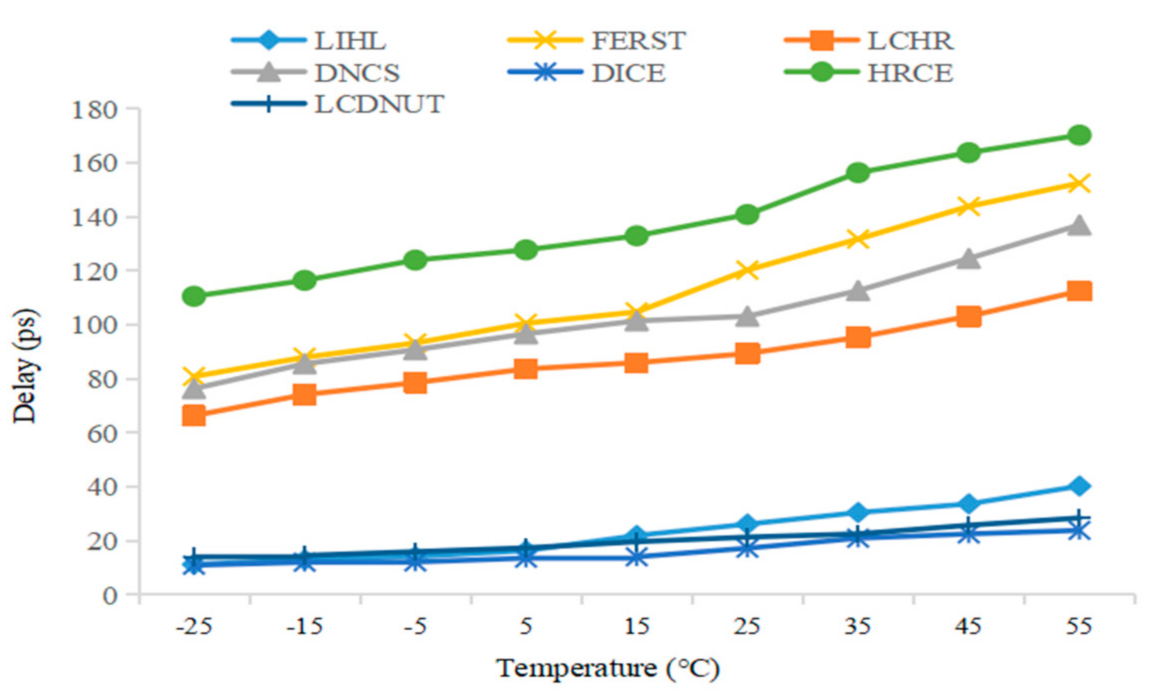
Figure 19.
Power consumption of various latch designs under different temperatures.

Figure 20.
Delay comparison of various latch designs under different Vth.
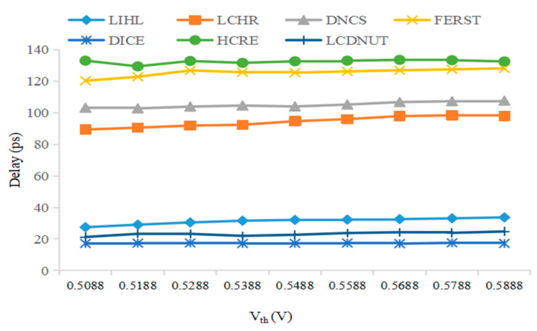
Figure 21.
Power consumption of various latch designs under different Vth.

Figure 22.
∆power, ∆delay, and ∆PDP of various latch designs compare to the proposed.


Table 1.
Examples of Different Tolerance Storage Cells.
| Latch | SEU Tolerance | SEDU Tolerance | SET Tolerance |
|---|---|---|---|
| DICE [16] | YES | NO | NO |
| FERST [27] | YES | NO | YES |
| DNCS [31] | YES | YES | NO |
| LCHR [28] | YES | NO | YES |
| HRCE [36] | YES | YES | NO |
| LCDNUT [37] | YES | YES | NO |
| LIHL (proposed) | YES | YES | YES |
Publisher’s Note: MDPI stays neutral with regard to jurisdictional claims in published maps and institutional affiliations. |
© 2021 by the authors. Licensee MDPI, Basel, Switzerland. This article is an open access article distributed under the terms and conditions of the Creative Commons Attribution (CC BY) license (https://creativecommons.org/licenses/by/4.0/).
Share and Cite
MDPI and ACS Style
Xu, H.; Liu, X.; Yu, G.; Liang, H.; Huang, Z. LIHL: Design of a Novel Loop Interlocked Hardened Latch. Electronics 2021, 10, 2090. https://doi.org/10.3390/electronics10172090
AMA Style
Xu H, Liu X, Yu G, Liang H, Huang Z. LIHL: Design of a Novel Loop Interlocked Hardened Latch. Electronics. 2021; 10(17):2090. https://doi.org/10.3390/electronics10172090
Chicago/Turabian StyleXu, Hui, Xuan Liu, Guo Yu, Huaguo Liang, and Zhengfeng Huang. 2021. "LIHL: Design of a Novel Loop Interlocked Hardened Latch" Electronics 10, no. 17: 2090. https://doi.org/10.3390/electronics10172090
Note that from the first issue of 2016, this journal uses article numbers instead of page numbers. See further details here.