
Analytical Study and Comparison of Electromagnetic Characteristics of 8-Pole 9-Slot and 8-Pole 12-Slot Permanent Magnet Synchronous Machines Considering Rotor Eccentricity


 , ,
, ,  , and
, and
Abstract
:1. Introduction
2. Electromagnetic Analysis of a PMSM Using Analytical Method
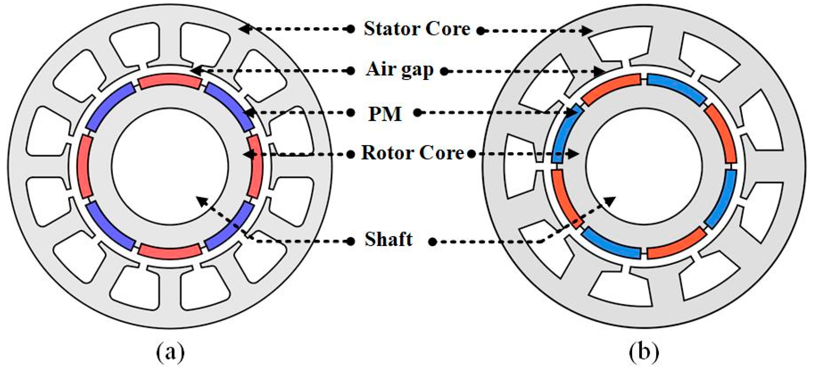
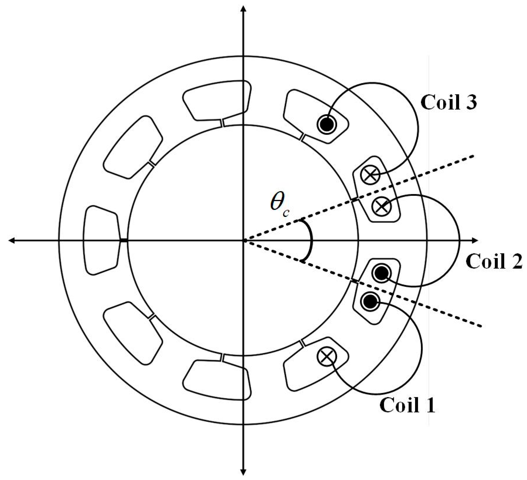
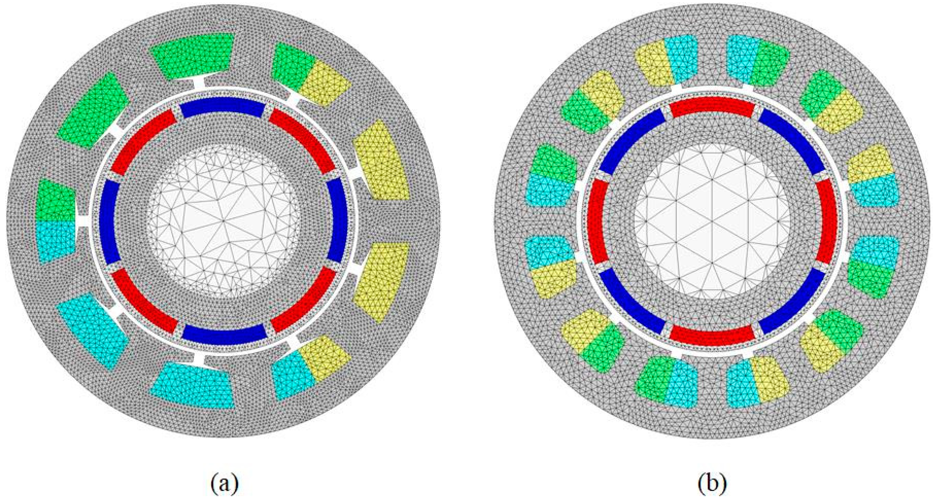
2.1. Analytical Model
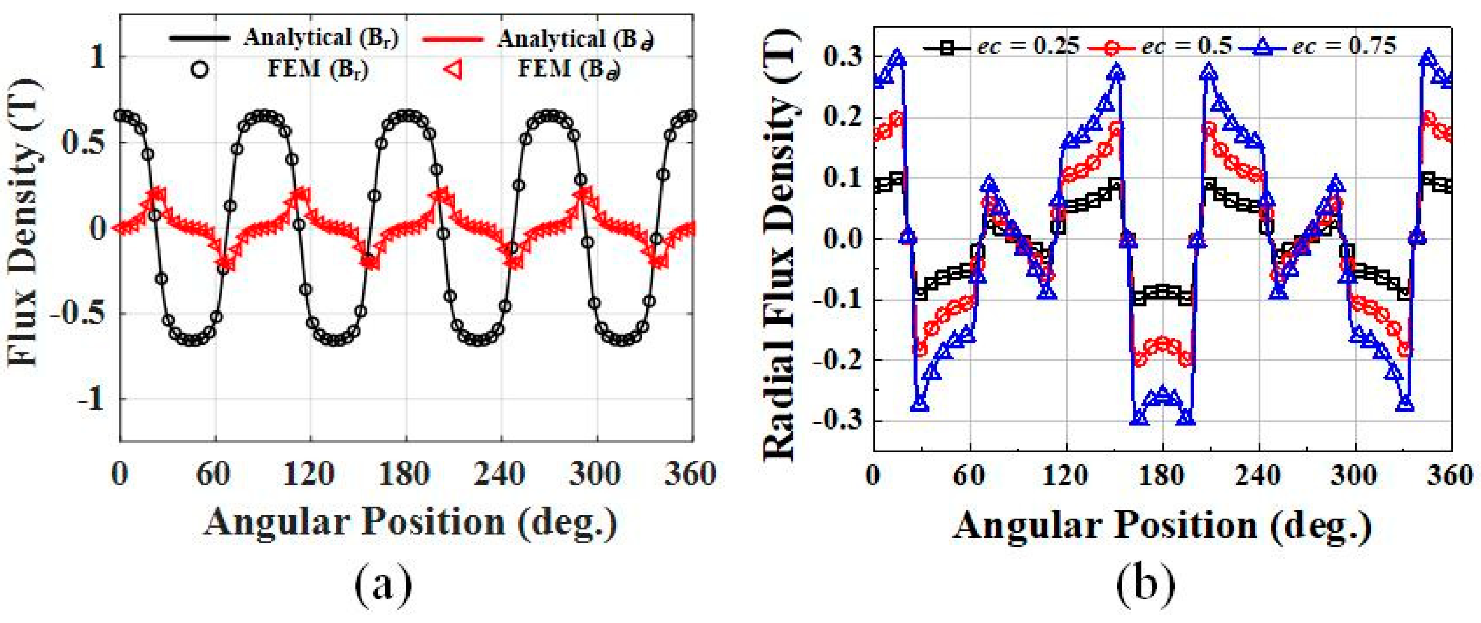
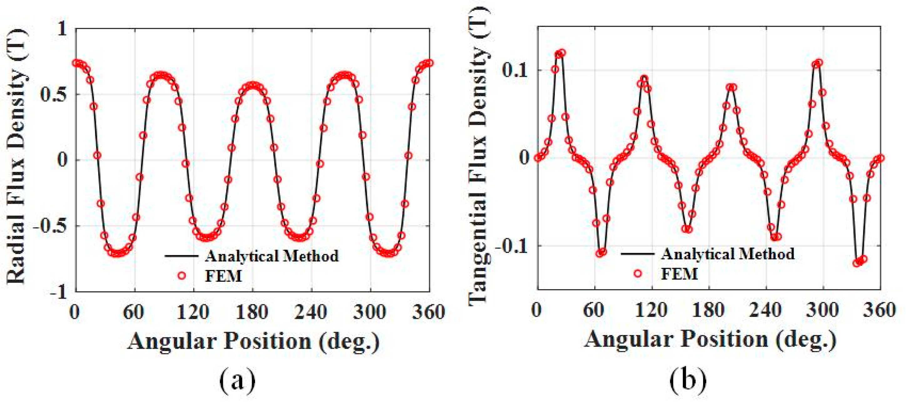
2.2. Magnetic Field Analysis Using Analytical Method
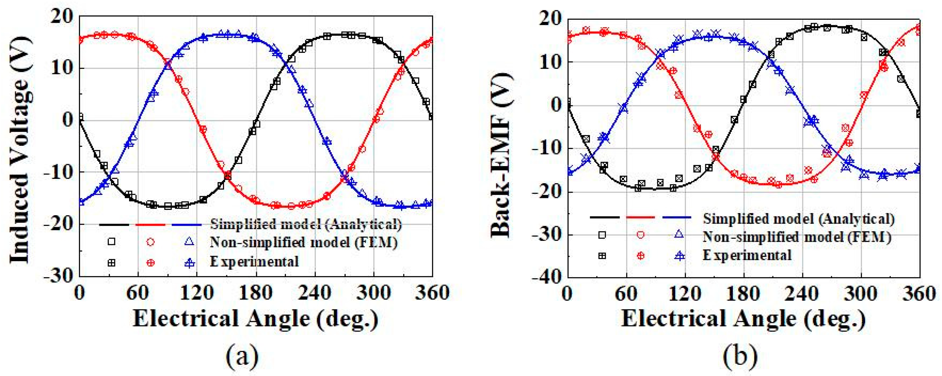
2.3. Back-EMF
3. Results and Discussion
4. Conclusions
Author Contributions
Funding
Data Availability Statement
Conflicts of Interest
References
- Goktas, T.; Zafarani, M.; Lee, K.W.; Akin, B.; Sculley, T. Comprehensive Analysis of Magnet Defect Fault Monitoring Through Leakage Flux. IEEE Trans. Magn. 2017, 53, 1–10. [Google Scholar] [CrossRef]
- Prieto, M.D.; Espinosa, A.G.; Ruiz, J.R.; Urresty, J.C.; Ortega, J.A. Feature extraction of demagnetization faults in PMSMs based on box-counting fractal dimension. IEEE Trans. Ind. Electron. 2011, 58, 1594–1605. [Google Scholar] [CrossRef]
- Hyun, D.; Hong, J.; Lee, S.B.; Kim, K.; Wiedenbrug, E.J.; Teska, M.; Nandi, S.; Chelvan, I.T. Automated Monitoring of Airgap Eccentricity for Inverter-Fed Induction Motors Under Standstill Conditions. IEEE Trans. 2011, 47, 1257–1266. [Google Scholar]
- Park, Y.; Fernandez, D.; Lee, S.B.; Hyun, D.; Jeong, M.; Kommuri, S.K.; Cho, C.; Reigosa, D.; Briz, F. On-line detection of rotor eccentricity for PMSMs based on Hall-effect field sensor measurements. In Proceedings of the 2017 IEEE Energy Conversion Congress and Exposition (ECCE), Cincinnati, OH, USA, 1–5 October 2017; pp. 4678–4685. [Google Scholar]
- Thomson, W.; Barbour, A. On-line current monitoring and application of a finite element method to predict the level of static airgap eccentricity in three-phase induction motors. IEEE Trans. Energy Convers. 1998, 13, 347–357. [Google Scholar] [CrossRef]
- Amirat, Y.; Benbouzid, M.E.H.; Bensaker, B.; Wamkeue, R. Condition monitoring and fault diagnosis in wind energy conversion systems: A review. In Proceedings of the IEEE PEMDC Conference, Antalya, Turkey, 3–5 May 2007. [Google Scholar]
- Lu, B.; Li, Y.; Wu, X.; Yang, Z. A review of recent advances in wind turbine condition monitoring and fault diagnosis. No. 24026. In Proceedings of the IEEE Conference on Power Electronics and Machines in Wind Applications (PEMWA), Lincoln, NE, USA, 24–26 June 2009; pp. 1–7. [Google Scholar]
- Yang, W.; Tavner, P.J.; Wilkinson, M. Wind Turbine Condition Monitoring and Fault Diagnosis Using Both Mechanical and Electrical Signatures. In Proceedings of the 2008 IEEE/ASME International Conference on Advanced Intelligent Mechatronics, Xi’an, China, 2–5 July 2008; pp. 1296–1301. [Google Scholar] [CrossRef]
- Kim, U.; Lieu, D.K. Magnetic field calculation in permanent magnet motors with rotor eccentricity: Without slotting effect. IEEE Trans. Magn. 1998, 34, 2242–2252. [Google Scholar] [CrossRef]
- Rahideh, A.; Korakianitis, T. Analytical open-circuit magnetic field distribution of slotless brushless permanent magnet machines with rotor eccentricity. IEEE Trans. Magn. 2011, 47, 4791–4808. [Google Scholar] [CrossRef]


| Parameter | Value | Unit |
|---|---|---|
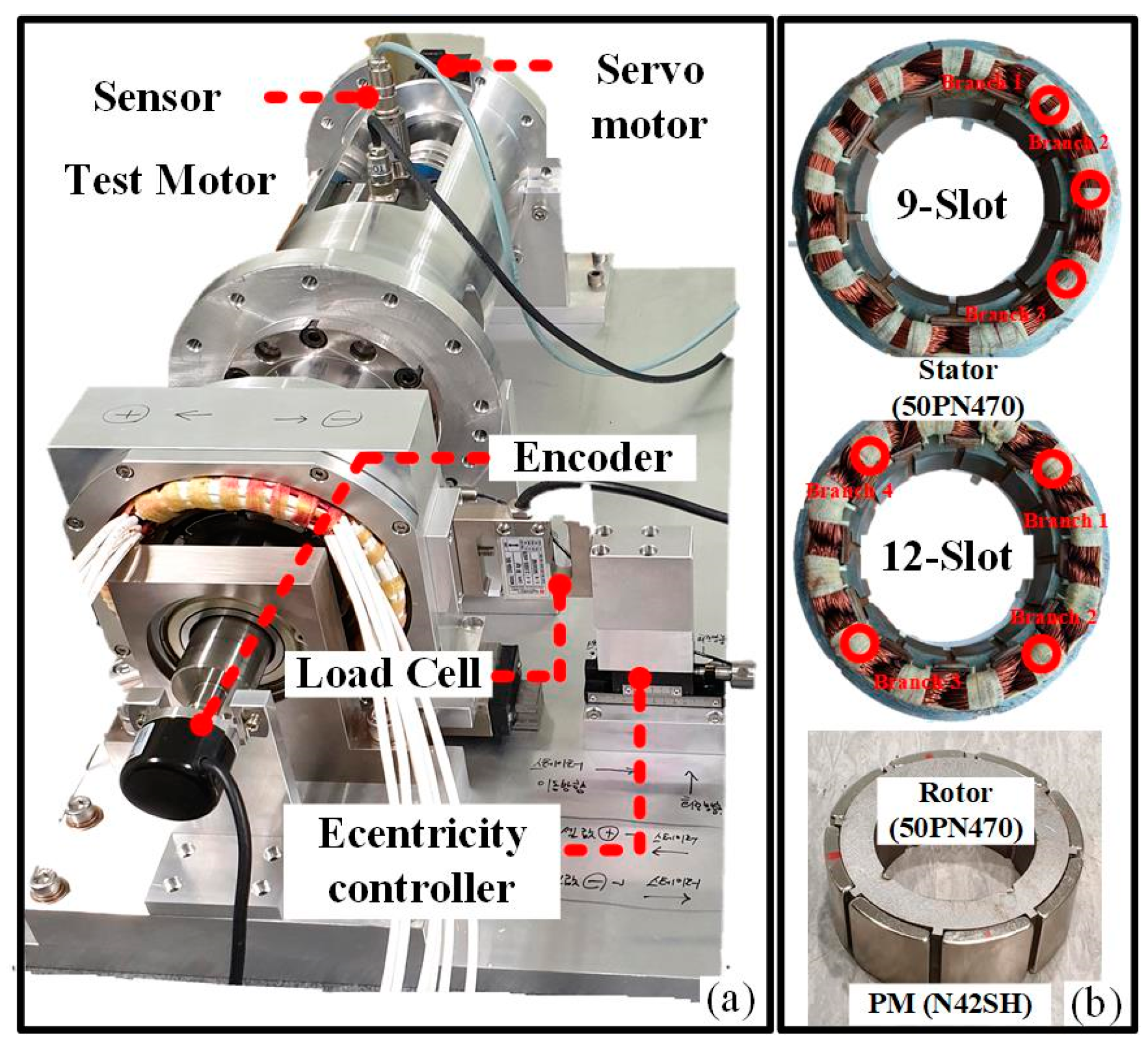
| Number of slots/poles | 9/8, 12/8 | mm |
| Outer radius of stator | 75 | mm |
| Inner radius of stator | 47 | mm |
| Outer radius of rotor | 43 | mm |
| Thickness of PMs | 5 | mm |
| Axial length | 30 | mm |
| Magnet remanence | 1.27 | T |
| Rated speed | 1000 | Rpm |
| Pole arc ratio | 0.9 |
| Parameter | Analytical | FEM | Measurement | |||
|---|---|---|---|---|---|---|
| 8p9s | 8p12s | 8p9s | 8p12s | 8p9s | 8p12s | |
| Number of meshes | - | - | 31,496 | 30,541 | - | - |
| Analysis time (s) | 0.11 | 0.12 | 11 | 23 | - | - |
| Back-EMF (Vmax) | 17.63 | 18.45 | 17.52 | 18.35 | 17.68 | 19.05 |
| Error (%) | 0.28 | 3.14 | 0.9 | 3.67 | - | - |
| Parameter | Analytical | FEM | Measurement | |||
|---|---|---|---|---|---|---|
| 8p9s | 8p12s | 8p9s | 8p12s | 8p9s | 8p12s | |
| Number of meshes | - | - | 31,839 | 33,910 | - | - |
| Analysis time (s) | 0.11 | 0.12 | 12 | 25 | ||
| Back-EMF (Vmax) | 18.36 | 18.45 | 18.2 | 18.35 | 18.6 | 19.04 |
| Error (%) | 1.29 | 3.1 | 2.15 | 3.62 | - | - |
Publisher’s Note: MDPI stays neutral with regard to jurisdictional claims in published maps and institutional affiliations. |
© 2021 by the authors. Licensee MDPI, Basel, Switzerland. This article is an open access article distributed under the terms and conditions of the Creative Commons Attribution (CC BY) license (https://creativecommons.org/licenses/by/4.0/).
Share and Cite
Lee, H.-K.; Bang, T.-K.; Lee, J.-I.; Woo, J.-H.; Shin, H.-S.; Yoon, I.-J.; Choi, J.-Y. Analytical Study and Comparison of Electromagnetic Characteristics of 8-Pole 9-Slot and 8-Pole 12-Slot Permanent Magnet Synchronous Machines Considering Rotor Eccentricity. Electronics 2021, 10, 2036. https://doi.org/10.3390/electronics10162036
Lee H-K, Bang T-K, Lee J-I, Woo J-H, Shin H-S, Yoon I-J, Choi J-Y. Analytical Study and Comparison of Electromagnetic Characteristics of 8-Pole 9-Slot and 8-Pole 12-Slot Permanent Magnet Synchronous Machines Considering Rotor Eccentricity. Electronics. 2021; 10(16):2036. https://doi.org/10.3390/electronics10162036
Chicago/Turabian StyleLee, Hoon-Ki, Tae-Kyoung Bang, Jeong-In Lee, Jong-Hyeon Woo, Hyo-Seob Shin, Ick-Jae Yoon, and Jang-Young Choi. 2021. "Analytical Study and Comparison of Electromagnetic Characteristics of 8-Pole 9-Slot and 8-Pole 12-Slot Permanent Magnet Synchronous Machines Considering Rotor Eccentricity" Electronics 10, no. 16: 2036. https://doi.org/10.3390/electronics10162036