
A 1-V 7th-Order SC Low-Pass Filter for 77-GHz Automotive Radar in 28-nm FD-SOI CMOS


1
STMicroelectronics, 95121 Catania, Italy
2
Dipartimento di Ingegneria Elettrica Elettronica e Informatica (DIEEI), University of Catania, 95125 Catania, Italy
*
Author to whom correspondence should be addressed.
Electronics 2021, 10(12), 1466; https://doi.org/10.3390/electronics10121466
Submission received: 20 May 2021
/
Revised: 12 June 2021
/
Accepted: 16 June 2021
/
Published: 18 June 2021
(This article belongs to the Special Issue RF/Mm-Wave Circuits Design and Applications)
Abstract
:This paper presents a switched capacitor low-pass filter in a 28-nm fully depleted silicon on insulator CMOS technology for 77-GHz automotive radar applications. It is operated at a power supply as low as 1 V and guarantees 5-dB in-band voltage gain while providing out-of-band attenuation higher than 36 dB and a programmable passband up to 30 MHz. A double sampling technique is adopted, which allows high operating frequency to be achieved while saving power. Moreover, low-voltage biasing and common-mode feedback circuits are exploited to guarantee an almost rail-to-rail output voltage swing. The proposed filter provides an output 1-dB compression point as high as 8.7 dBm with a power consumption of 9 mW. To the authors’ knowledge, this is the first SC-based implementation of a low pass filter for automotive radar applications.
1. Introduction
Millimeter-wave (mm-wave) radar sensors represent an enabling technology for the development of advanced driving assistance systems (ADASs) [1]. Such systems rely on a relatively high number of sensors arranged throughout the car. They provide features such as adaptive cruise control (ACC), anti-collision warning, pre-crash detection, etc., with the aim of improving driving safety standards [2]. Modern automotive radar sensors typically adopt System in Package (SiP) implementations exploiting BiCMOS technologies [3,4,5]. However, the increasing demand for a widespread adoption of ADASs calls for System-on-Chip (SoC) implementations. Presently, the CMOS technology provides the most promising solution for the implementation of monolithic mm-wave low-cost radar sensors [6]. Indeed, technology scaling greatly improved frequency performance of CMOS transistors [7,8,9,10,11,12] enabling both mm-wave circuits and the microcontroller to be implemented on the same chip. However, such scaling inevitably leads to a substantial reduction of the supply voltage, and this translates into a more critical design mainly due to voltage headroom limitations.
Figure 1a depicts a simplified block-diagram of a typical radar sensor receiver (RX). It exploits a frequency-modulated continuous-wave (FMCW) architecture for reduced complexity and basically consists of a mm-wave front end and a wide-band analog baseband [13]. The RX design poses non-trivial challenges at the mm-wave side due to the high operating frequency and the low-noise requirement. A mixer-first receiver architecture allows higher linearity to be achieved since it avoids further RF amplification [3,4,13]. Nevertheless, the design of the baseband circuitry is crucial as well. It consists of a variable gain amplifier (VGA) and a low-pass filter, which process the received signal to make it suitable for the analog-to-digital converter (ADC).
At the baseband side, the design challenges are mainly related to the linearity requirement, and this issue is particularly critical for the low-pass filter (LPF) since it has to provide a high swing linear signal to the converter. The LPF is a key building block of the radar receiver. Indeed, it acts as antialiasing filter besides rejecting undesired out-of-band signals. As a consequence, the LPF defines the actual signal bandwidth, BWA, at the input of the ADC, thus posing a constrain on the minimum sampling frequency and ultimately on its current consumption. As shown in Figure 1b, BWA in a typical low-accuracy LPF greatly suffers from PVT variations and/or poor selectivity, thus resulting in a higher and higher ADC sampling frequency. Therefore, designing a high selectivity LPF that may also guarantee robustness over PVT variations is essential for the implementation of low-current consumption radar sensors. Furthermore, the LPF cut-off frequency should be programmable to well comply with both long- and short-range radar applications. State-of-the-art LPFs for radar applications typically rely on R-C [10,11,12,13,14,15,16] or Gm-C [17,18] architectures. R-C topologies exploit operational amplifiers (OPAMPs), resistors and capacitors to define the transfer-function poles and zeros. In these filters, the cut-off frequency is set by digitally controlling resistors and/or capacitors [19], thus providing a discrete tuning. Such approach guarantees good linearity performance at the cost of both high-power consumption and high-area occupation. Conversely, Gm-C filters rely on transconductors and capacitors to set the transfer-function poles and zeros. This enables cut-off frequency tuning by adjusting the transconductor bias current [20]. However, SC filters have larger bandwidth programmability and exhibit better linearity performance than Gm-C filters, since they use purely capacitive feedback network and load, which further improve linearity [21]. Moreover, both R-C and Gm-C active filters suffer from high sensitivity to PVT variations. Therefore, to achieve an acceptable accuracy they require an automatic tuning that increases complexity.
In this paper, a seventh order switched capacitor (SC) low-pass filter for automotive radar applications is presented, which provides very high selectivity while guaranteeing high accuracy. The filter allows an ADC sampling frequency as low as twice the signal bandwidth to be adopted, which drastically reduces power consumption. Moreover, the SC technique guarantees high linearity, since it is based on the capacitive feedback approach, and provides wide programmability of the cut-off frequency by simply varying the sampling frequency. The proposed SC LPF has been implemented in 28-nm fully depleted (FD) silicon on insulator (SOI) CMOS technology and exploits a double sampling technique to achieve high operating frequency while saving current consumption.
This paper is organized as follows. Section 2 deals with the filter design and gives insights on both the FD-SOI CMOS technology and the adopted circuit solutions for low-voltage operation. Experimental results are presented in Section 3, which also provides a comparison with the state of the art. Finally, conclusions are drawn in Section 4.
2. Filter Design
The design of an SC low-pass filter with both high bandwidth and selectivity poses several challenges in the operational transconductance amplifier (OTA) design, especially when, as in this case, an almost rail-to-rail output swing is important to reduce the ADC complexity. Indeed, high selectivity requires a high-order filter and a high gain OTA, whereas high bandwidth means high sampling frequency that in turn leads to high current consumption [22]. In this scenario, technology platform as well as proper circuit design are crucial to achieve high bandwidth and high selectivity while preserving output swing and saving current, despite a low supply voltage.
2.1. Technology Platform
The 28-nm FD-SOI CMOS technology features flipped-well low-threshold-voltage, (LVT) transistors [23]. Both n-MOS and p-MOS devices are fabricated in a 7-nm layer of silicon, which is embedded between a 250-nm gate oxide and a 25-nm buried oxide (BOX). Thanks to the technology scaling, very high frequency operation is achieved (i.e., about 300-GHz transition frequency) thus enabling mm-wave implementation. However, the thin-gate oxide imposes a power supply voltage as low as 1 V and this entails severe limitations in the circuit design to preserve signal swing and linearity despite the low threshold voltage (i.e., around 250 mV in nominal condition). In the adopted technology, the body gain factor (i.e., the variation of VT with the body voltage) is around 90 mV/V and can be profitably exploited to further reduce the transistor threshold voltage down to 150 mV, which is very useful in a low-voltage design.
2.2. Circuit Description
The operating range of automotive radar sensors spans from a few meters up to 250 m according to the different application scenario. This results in an IF signal bandwidth up to 10 and 20 MHz, for short- and long-range applications, respectively. Therefore, the LPF should provide a programmable wide operating bandwidth along with high selectivity. To these purposes, SC is the best approach since it guarantees high accuracy and selectivity while providing flexibility. Therefore, it is the most suitable solution for the implementation of the LPF in future radar sensors. Incidentally, SC filter passband can be continuously tuned by merely changing the sampling frequency (fS). Of course, SC filters suffer from poor noise performance. Nevertheless, the SC approach is fully compliant with the radar application thanks to the high receiver gain that makes negligible the contribution of the LPF to the overall receiver noise performance. Indeed, according to the Friis formula, the noise factor of the receiver (NFRX) can be approximately written as follows
where NFMIX, NFVGA, and NFLPF are the noise factors of the mixer, VGA, and LPF, respectively, whereas GMIX and GVGA are the voltage gain of mixer and VGA, respectively. Assuming an overall gain for the mixer and VGA higher than 60 dB, the noise contribution of the LPF to NFRX according to (1) is usually negligible.
For this design, a seventh-order elliptic SC low-pass filter was adopted to provide a 20-MHz passband along with a stopband laying very close (i.e., a few megahertz) to the passband cut-off frequency. This allows exploiting an almost 40-MHz sampling frequency for the ADC with a substantial reduction of current consumption. A simplified schematic of the proposed filter is shown in Figure 2. For the sake of clarity, the single-ended implementation is reported, although the designed solution is fully differential to make simple double sampling and greatly reduce substrate and power supply noise injection. The double sampling [24] is used to lower by a factor 2 the clock frequency for a given sampling frequency, thus increasing the time for settling by 2 and saving current consumption.
The filter consists of seven SC integrators implemented by the OTAs and feedback capacitors, C1–7. Capacitors C1,3, C3,1, C3,5, C5,3, C5,7, and C7,5 provide the transmission zeros; capacitors CS and CL perform the source and load terminations, and the other capacitors accomplish the input signal sampling. Figure 3 shows the RLC passive prototype of the proposed filter, whose component values are reported in Table 1 for the sake of completeness. Thanks to the three transmission zeros (i.e., L2-C2, L4-C4, L6-C6) the filter achieves an out-of-band attenuation as high as 45 dB at just 1 MHz from the passband.
The key building block of the SC LPF is the integrator, whose inverting implementation is reported in Figure 4 along with the detailed schematic of the OTA. The latter poses several design challenges mainly due to the high gain-bandwidth product required by the high sampling frequency along with the low supply voltage. To achieve the targeted 20-MHz passband, the filter is to be operated with a 200 MHz sampling frequency, which means that the OTA should guarantee an accurate settling within 5 ns. Considering a percentage of the time response dominated by slewing conditions, this translates into a transition frequency as high as 500 MHz. Furthermore, a rail-to-rail output signal is to be provided to relax the ADC resolution while preserving signal-to-quantization noise ratio.
To fulfill such specifications, a full swing two-stage OTA was used in this work, which exploits a low-voltage biasing and an SC common-mode feedback circuit, which provides linear operation even with rail-to-rail output signal.
The OTA consists of a first gain stage based on an active-loaded differential pair, M1-4, and a common-source second gain stage, M6–9, which provides an almost rail-to-rail output signal. Transistors M10–12 implement a low-voltage biasing, which is required by the 1-V operation. Specifically, the bias current of the first stage, IB1, is provided by M5 that is in a current mirror configuration with M10. By setting the same current density for M1,2 and M11,12, the drain-source voltages of M5 and M10 are approximately the same. This allows IB1 to be accurately set even though M5 and M10 could be pushed into triode region due to PVT variations. Nevertheless, the back-gate terminals of M1,2 and M11,12 are connected to VDD to minimize their threshold voltage and hence increase the drain-source voltages of M5 and M10. All the transistors are biased in the saturation region although M10 and M5 can well work even in the triode region, thanks to the low-voltage biasing, M10–12. A common-mode feedback circuit (CMF) sets the output bias voltage to VDD/2 to preserve full output swing. The designed OTA exploits Miller compensation to guarantee a phase margin of 60° with a transition frequency of 500 MHz and achieves an open-loop gain as high as 60 dB. Table 2 summarizes the main transistors parameters of the OTA, whose current consumption is around 1 mA.
3. Experimental Results
The SC LPF was integrated in a 28-nm FD-SOI CMOS technology by STMicroelectronics within a complete 77-GHz radar receiver [25]. The adopted backend-of-line (BEOL) provides eight copper layers in addition to a top aluminum one. Metal-oxide-metal (MOM) capacitors with 5-fF/μm2 are also available A microphotograph of the SC LPF is shown in Figure 5. The core area is about 775 × 265 µm2. The die was directly assembled chip-on-board on a FR4 printed circuit board (PCB) to enable a complete filter characterization. All measurements were performed at 1-V supply voltage.
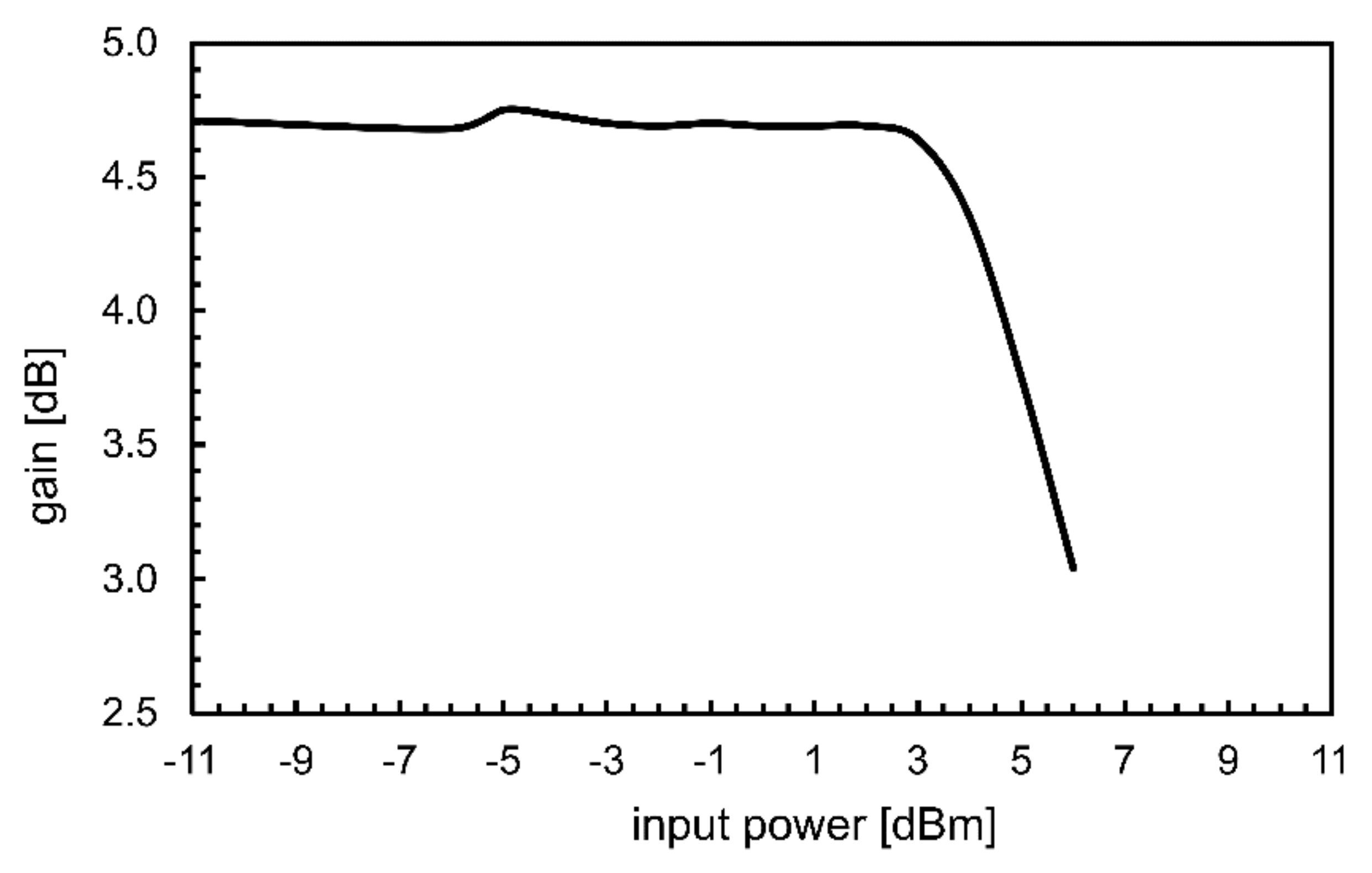
Figure 6 shows the measured frequency response for different values of the sampling clock. Measurements show proper filter operation up to 300 MHz sampling frequency that results in a maximum cut-off frequency as high as 30 MHz. Moreover, the filter provides a 5-dB voltage gain to relax the VGA linearity and an in-band ripple ranging from 0.8 dB to 2.6 dB, as shown in Figure 7. Out-of-band attenuation goes from 42 dB to 36 dB, when the sampling frequency spanning from 100 MHz to 300 MHz. The OTA finite gain and bandwidth affect the filter performance thus resulting on a higher ripple and lower out-of-band attenuation with respect to the passive prototype. The linearity performance was also tested by measuring the in-band 1 dB input compression point, IP1dB, as shown in Figure 8.
Thanks to both the capacitive feedback architecture of SC filters and the adopted OTA solution, the filter exhibits excellent linearity performance by providing around 5-dBm IP1dB, which results in a linear output swing as high as 850 mV. For the sake of completeness, the input-referred noise (IRN) density was also measured at the maximum passband (i.e., 30 MHz). The measured IRN is around 42 nV/√Hz at 15 MHz.
The measured performance is summarized and compared with the state of the art in Table 3. The proposed LPF exhibits a higher IRN than the other works. However, as mentioned above, the filter noise is not a meaningful parameter for automotive radar applications. Conversely, the proposed SC LPF exhibits the best-in-class performance in terms of selectivity, bandwidth, and linearity at 1-V supply voltage.
4. Conclusions
A seventh order SC low-pass filter has been presented, which is implemented in 28-nm FD-SOI CMOS. The proposed SC LPF provides very high selectivity while achieving high accuracy. Specifically, an out of band attenuation higher than 36 dB is achieved while providing a linear output voltage swing as high as 850 mV at 1-V supply voltage. Moreover, the passband can be tuned up to 30 MHz by merely changing the sampling frequency thus providing high flexibility. To the authors’ knowledge, this is the first SC-based implementation of a LPF for automotive radar applications.
Author Contributions
Conceptualization, A.P. and G.P. (Giuseppe Palmisano); validation, A.P. and G.P (Giuseppe Papotto); formal analysis, A.P.; methodology, A.P.; project administration, G.P. (Giuseppe Palmisano); supervision, G.P. and E.R.; writing—original draft, A.P., E.R., G.P. (Giuseppe Papotto), G.P. (Giuseppe Palmisano); writing—review and editing, E.R. All authors have read and agreed to the published version of the manuscript.
Funding
This research received no external funding.
Data Availability Statement
The data presented in this study are available on request from the corresponding author.
Acknowledgments
The authors would like to thank A. Castorina and A. Caruso at STMicroelectronics for measurements and layout support, respectively.
Conflicts of Interest
The authors declare no conflict of interest.
References
- Hung, C.; Lin, A.T.C.; Peng, B.C.; Wang, H.; Hsu, J.-L.; Lu, Y.-J.; Hsu, W.; Zhan, J.-H.C.; Juan, B.; Lok, C.-H.; et al. Toward automotive surround-view radars. In Proceedings of the IEEE Int. Solid-State Circuits Conference Digest of Technical Papers, San Francisco, CA, USA, 17–21 February 2019; pp. 162–164. [Google Scholar]
- Takács, Á.; Rudas, I.; Bösl, D.; Haidegger, T. Highly automated vehicles and self-driving cars. IEEE Robot. Autom. Mag. 2018, 25, 106–112. [Google Scholar] [CrossRef]
- Trotta, S.; Wintermantel, M.; Dixon, J.; Moeller, U.; Jammers, R.; Hauck, T.; Samulak, A.; Dehlink, B.; Shun-Meen, K.; Li, H.; et al. An RCP packaged transceiver chipset for automotive LRR and SRR systems in SiGe BiCMOS technology. IEEE Trans. Microw. Theory Tech. 2012, 60, 778–794. [Google Scholar] [CrossRef]
- Fujibayashi, T.; Takeda, Y.; Wang, W.; Yeh, Y.-S.; Stapelbroek, W.; Takeuchi, S.; Floyd, B. A 76-to 81-GHz multi-channel radar transceiver. IEEE J. Solid State Circuits 2017, 52, 2226–2241. [Google Scholar] [CrossRef]
- Belfiore, F.; Calcagno, A.; Borgonovo, G.; Castro, M.G.; Pisasale, A.; Platania, M.; Vinciguerra, M.; Schiro’, C.; Alessi, G.; Burgio, C.; et al. A 76 to 81GHz packaged transceiver for automotive radar with FMCW modulator and ADC. In Proceedings of the European Radar Conference (EURAD), Nuremberg, Germany, 11–13 October 2017; pp. 143–146. [Google Scholar]
- Ding, B.; Yuan, S.; Zhao, C.; Tao, L.; Tian, T. A Ka band FMCW transceiver front-end with 2-GHz bandwidth in 65-nm CMOS. IEEE Trans. Circuits Syst. II Express Briefs 2019, 66, 212–216. [Google Scholar] [CrossRef]
- Hsiao, Y.-H.; Chang, Y.-C.; Tsai, C.-H.; Huang, T.-Y.; Aloui, S.; Huang, D.-J.; Chen, Y.-H.; Tsai, P.-H.; Kao, J.-C.; Lin, Y.-H.; et al. A 77-GHZ 2T6R transceiver with injection-lock frequency sextupler using 65-nm CMOS for automotive radar system application. IEEE Microw. Theory Tech. 2016, 64, 3031–3048. [Google Scholar] [CrossRef]
- Ginsburg, B.P.; Subburaj, K.; Samala, S.; Ramasubramanian, K.; Singh, J.; Bhatara, S.; Murali, S.; Breen, D.; Moallem, M.; Dandu, K.; et al. A multimode 76-to-81 GHz automotive radar transceiver with autonomous monitoring. In Proceedings of the IEEE International Solid-State Circuits Digest of Technical Papers, San Francisco, CA, USA, 11–15 February 2018; pp. 158–160. [Google Scholar]
- Texas Instruments. 76-GHz to 81-GHz High-Performance Automotive MMIC. Available online: http://www.ti.com/product/AWR1234. (accessed on 20 May 2021).
- Jia, H.; Kuang, L.; Zhu, W.; Wang, Z.; Ma, F.; Wang, Z.; Chi, B. A 77-GHz frequency doubling two-path phased-array FMCW transceiver for automotive radar. IEEE J. Solid State Circuits 2016, 51, 2299–2311. [Google Scholar] [CrossRef]
- Pan, D.; Duan, Z.; Wu, B.; Wang, Y.; Huang, D.; Wang, Y.; Gui, P.; Sun, L. A digitally controlled CMOS receiver with -14 dBm P1dB for 77 GHz automotive radar. In Proceedings of the IEEE Int. Symp. Circuits Syst. (ISCAS), Sapporo, Japan, 26–29 May 2019; pp. 1–4. [Google Scholar]
- Nocera, C.; Papotto, G.; Cavarra, A.; Ragonese, E.; Palmisano, G. A 13.5-dBm 1-V power amplifier for W-band automotive radar applications in 28-nm FD-SOI CMOS technology. IEEE Trans. Microw. Theory Tech. 2021, 69, 1654–1660. [Google Scholar] [CrossRef]
- Saponara, S.; Greco, M.; Ragonese, E.; Palmisano, G.; Neri, B. Radar for automotive applications: Signal processing perspective. In Highly Integrated Low Power Radars; Artech House: Norwood, MA, USA, 2014; pp. 89–113. [Google Scholar]
- Nocera, C.; Cavarra, A.; Ragonese, E.; Palmisano, G.; Papotto, G. Down-converter solutions for 77-GHz automotive radar sensors in 28-nm FD-SOI CMOS technology. In Proceedings of the 2018 14th Conference on Ph.D. Research in Microelectronics and Electronics (PRIME), Prague, Czech Republic, 2–5 July 2018; pp. 153–156. [Google Scholar]
- Lavalle-Aviles, F.; Sánchez-Sinencio, E. A 0.6-V power-efficient active-RC analog low-pass filter with cutoff frequency selection. IEEE Trans. Very Large Scale Integr. VLSI Syst. 2020, 28, 1757–1769. [Google Scholar] [CrossRef]
- Zhang, C.; Shang, L.; Wang, Y.; Tang, L. A CMOS programmable fourth-order butterworth active-RC low-pass filter. Electronics 2020, 9, 204. [Google Scholar] [CrossRef] [Green Version]
- Lo, T.; Hung, C.; Ismail, M. A wide tuning range Gm-C filter for multi-mode CMOS direct-conversion wireless receivers. IEEE J. Solid State Circuits 2009, 44, 2515–2524. [Google Scholar] [CrossRef]
- Saari, V.; Kaltiokallio, M.; Lindfors, S.; Ryynanen, J.; Halonen, K.A.I. A 240-MHz low-pass filter with variable gain in 65-nm CMOS for a UWB radio receiver. IEEE Trans. Circuits Syst. I Regul. Pap. 2009, 56, 1488–1499. [Google Scholar] [CrossRef]
- Lim, J.; Kim, J. A 20-kHz~16-MHz programmable-bandwidth 4th order active filter using gain-boosted opamp with negative resistance in 65-nm CMOS. IEEE Trans. Circuits Syst. II Express Briefs 2019, 66, 182–186. [Google Scholar] [CrossRef]
- Lo, T.; Hung, C. 1V CMOS Gm-C Filters: Design and Applications; Springer: Berlin, Germany, 2009. [Google Scholar]
- Scaumann, R.; Ghausi, M.S.; Laker, K.R. Design of Analog Filters: Passive, Active RC, and Switched Capacitor; Prentice Hall: Englewood Cliffs, NJ, USA, 1990. [Google Scholar]
- Gregorian, R.; Temes, G.C. Analog MOS Integrated Circuits for Signal Processing; Wiley: Hoboken, NJ, USA, 2008. [Google Scholar]
- Cathelin, A. Fully depleted silicon on insulator devices CMOS: The 28 nm node is the perfect technology for analog, RF, mmW, and mixed signal system-on-chip integration. IEEE Solid State Circuits Mag. 2017, 9, 18–26. [Google Scholar] [CrossRef]
- Aloisi, W.; Giustolisi, G.; Palumbo, G. Exploiting the high-frequency performance of low-voltage low-power SC filters. IEEE Trans. Circuits Syst. II Express Briefs 2004, 51, 77–84. [Google Scholar] [CrossRef]
- Papotto, G.; Nocera, C.; Finocchiaro, A.; Parisi, A.; Cavarra, A.; Castorina, A.; Ragonese, E.; Palmisano, G. A 27-mW W-band radar receiver with effective TX leakage suppression in 28-nm FD-SOI CMOS. IEEE Trans. Microw. Theory Tech. Early Access 2021. [Google Scholar] [CrossRef]
- Zhao, Y.; Mak, P.; Martins, R.P.; Maloberti, F. A 0.02 mm2 59.2 dB SFDR 4th-order SC LPF with 0.5-to-10 MHz bandwidth scalability exploiting a recycling SC-buffer biquad. IEEE J. Solid-State Circuits 2015, 50, 1988–2001. [Google Scholar] [CrossRef]
Figure 1.
(a) Simplified block-diagram of a FMCW receiver. (b) LPF actual bandwidth over different accuracy.
Figure 1.
(a) Simplified block-diagram of a FMCW receiver. (b) LPF actual bandwidth over different accuracy.
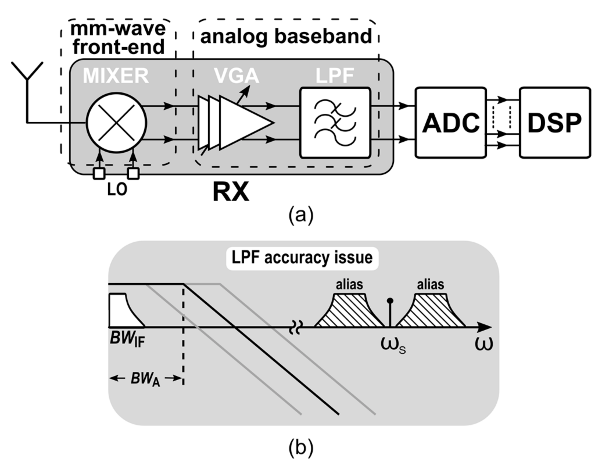
Figure 2.
Single-ended simplified schematic of the proposed seventh-order SC LPF.

Figure 3.
Ladder prototype of the SC LPF. Reproduced from [25]. Copyright 2021, IEEE.
Figure 3.
Ladder prototype of the SC LPF. Reproduced from [25]. Copyright 2021, IEEE.
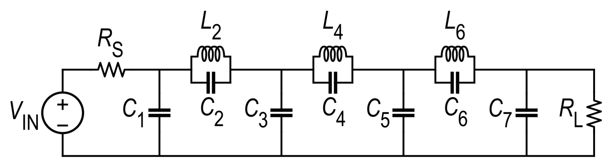
Figure 4.
Schematic of a differential inverting SC integrator.
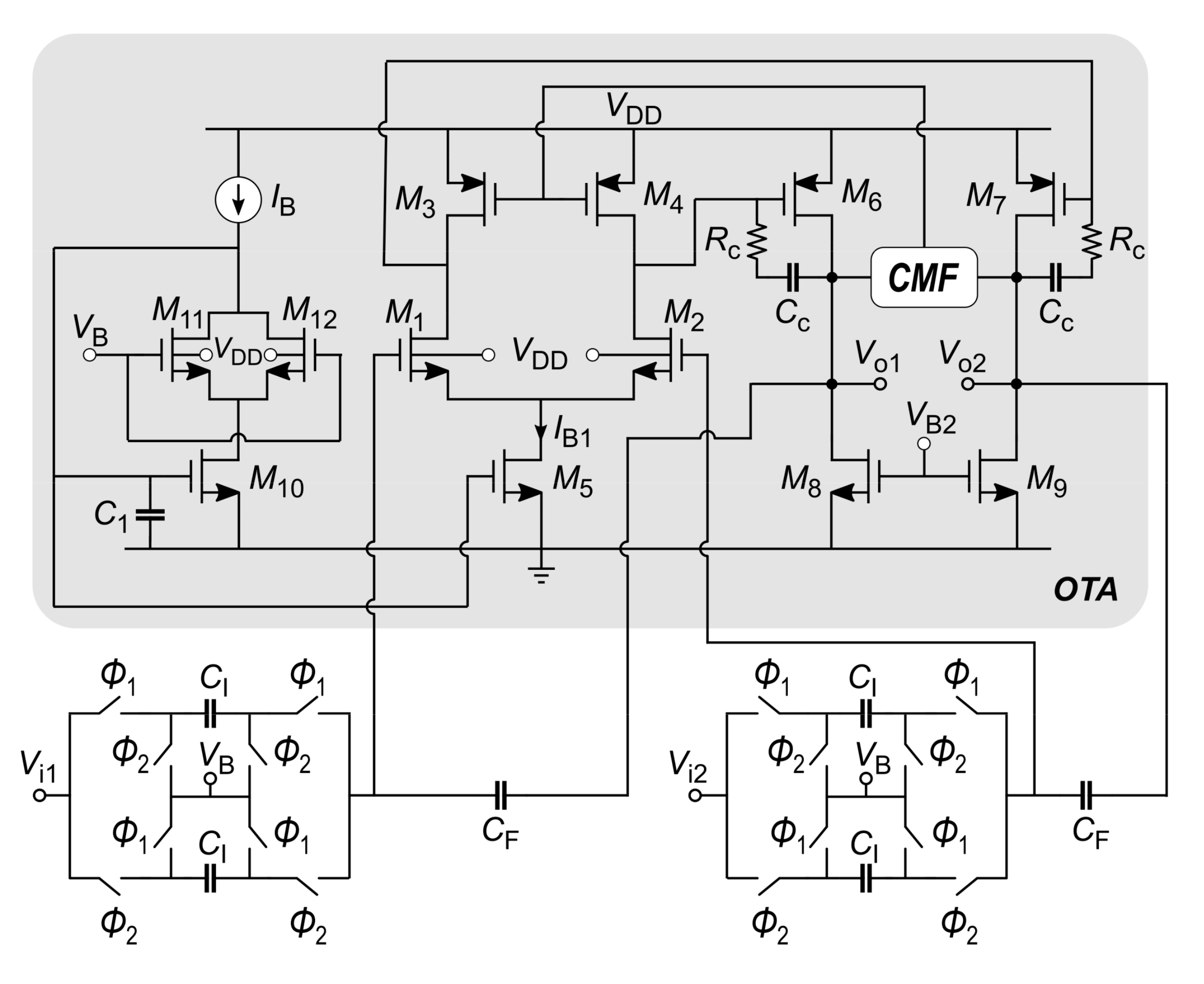
Figure 5.
Micrograph of the seventh order SC low-pass filter in a complete 77-GHz radar receiver. Reproduced from [25]. Copyright 2021, IEEE.
Figure 5.
Micrograph of the seventh order SC low-pass filter in a complete 77-GHz radar receiver. Reproduced from [25]. Copyright 2021, IEEE.
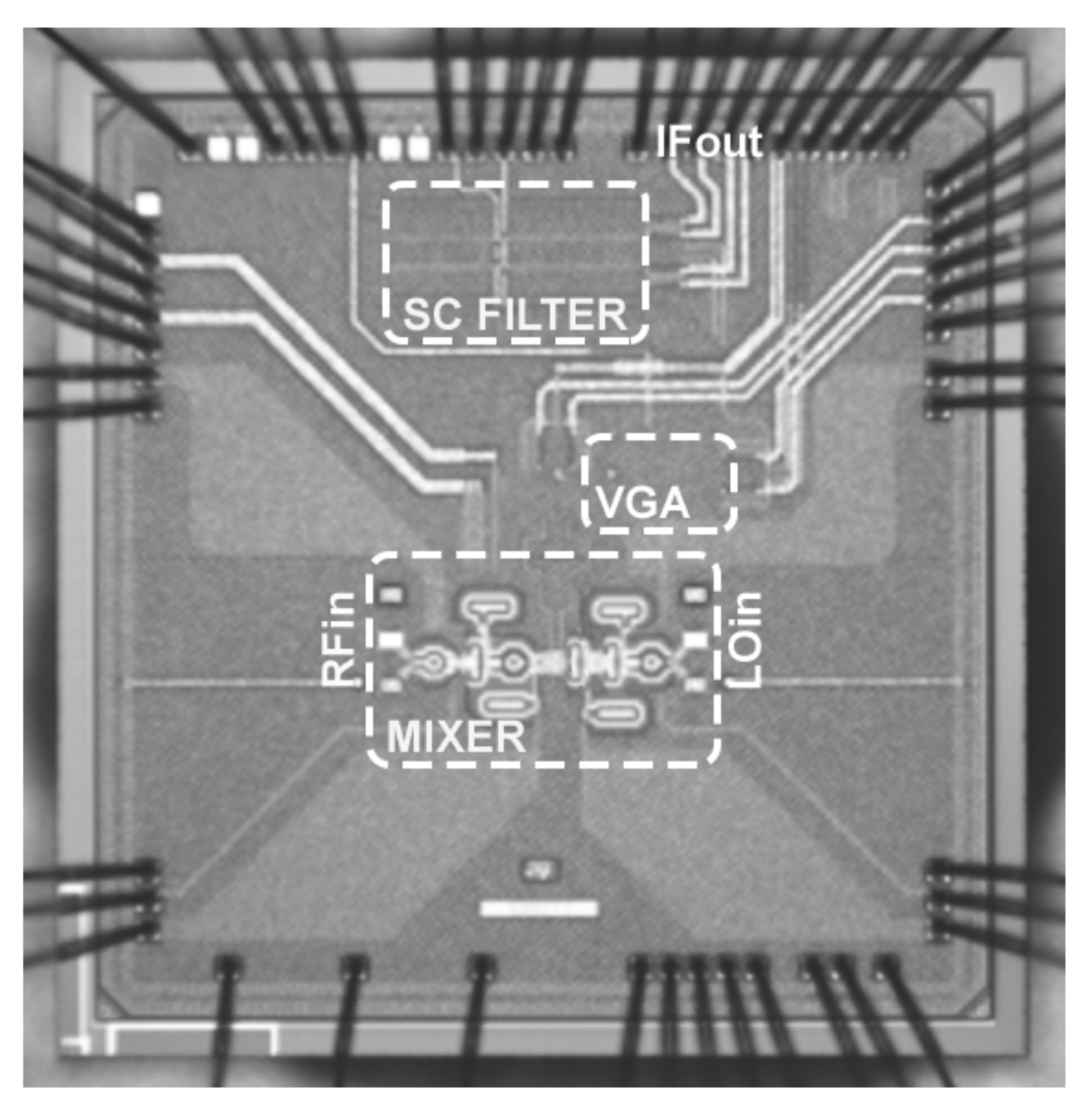
Figure 6.
Measured LPF frequency response for different values of the sampling frequency.
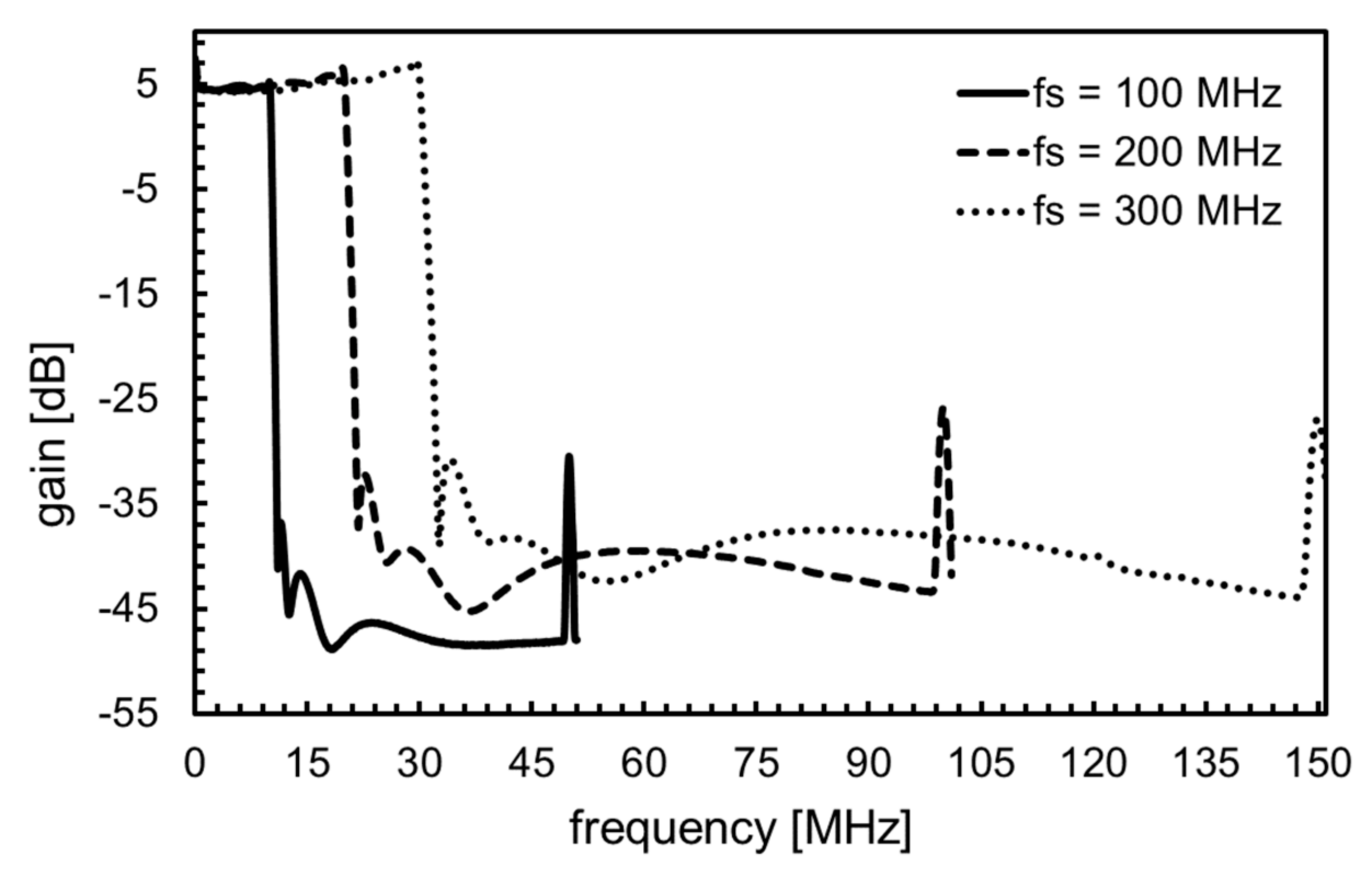
Figure 7.
Detail of the LPF in-band response for different values of the sampling frequency.
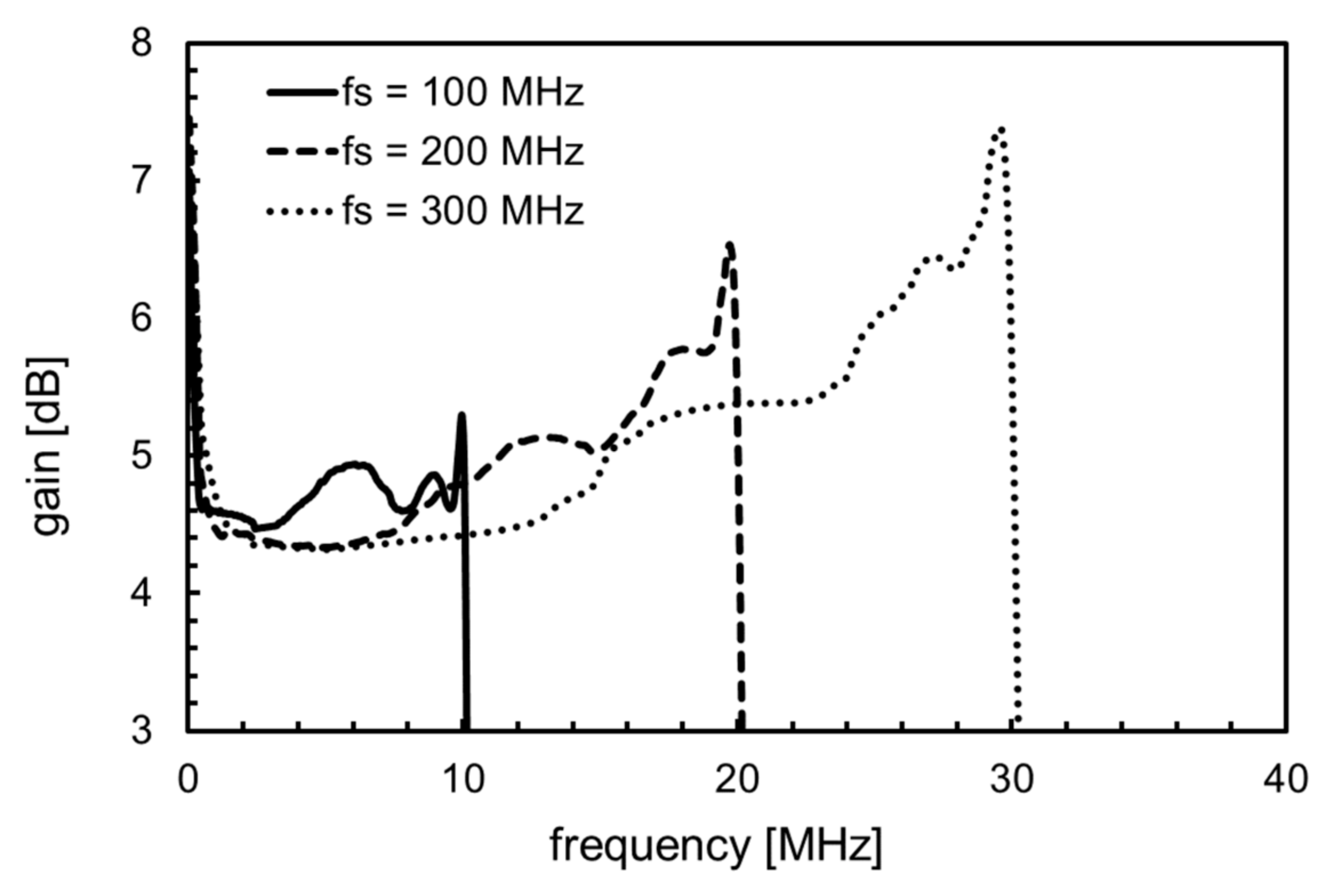
Figure 8.
Measured in-band gain as a function of the input power.

Table 1.
Component parameters for the RLC ladder prototype.
| Component | Size | Component | Size |
|---|---|---|---|
| RS | 50 Ω | C6 | 288.12 pF |
| C1 | 403.23 pF | C7 | 276.80 pF |
| C2 | 77.09 pF | L2 | 854.7 nH |
| C3 | 464.58 pF | L4 | 450.27 nH |
| C4 | 421.98 pF | L6 | 531.72 nH |
| C5 | 376.90 pF | RL | 50 Ω |
Passband ripple: 0.3 dB; passband frequency: 10.34 MHz; stopband attenuation: 45 dB; stopband frequency: 11.46 MHz.
Table 2.
Parameters of the OTA transistors.
| Component | Length [nm] | Width [µm] | Current [µA] |
|---|---|---|---|
| M1–2 | 60 | 21.6 | 10 |
| M3–4 | 160 | 3.6 | 10 |
| M5 | 500 | 105 | 20 |
| M6–7 | 60 | 115.2 | 400 |
| M8–9 | 500 | 204.8 | 400 |
| M10 | 500 | 52.5 | 10 |
| M11–12 | 60 | 10.8 | 5 |
Table 3.
Summarized performance and comparison with the state of the art.
| Parameters | [15] | [16] | [17] | [19] | [24] | [26] | This Work |
|---|---|---|---|---|---|---|---|
| Technology [nm] | 130 | 180 | 180 | 65 | 350 | 65 | 28 |
| Technique | Active RC | Active RC | Gm-C | Active RC | SC | SC-Buffer Biquad. | SC |
| Supply voltage [V] | 0.6 | 1.8 | 1.2 | 1.8 | 1.5 | 1.2 | 1 |
| Order, N | 4 | 4 | 3 | 4 | 5 | 4 | 7 |
| Bandwidth (BW) [MHz] | up to 160 | 0.6–2.15 | 20 | 0.02–16 | 6–8 | 0.5–10 | up to 30 MHz |
| Filter gain [dB] | 0 | 0 | 0 | 0 | 0 | 0 | 5 |
| OIP3 [dBm] | 9.56 | −6.5 | 18 | 21.1 | n.a. | 16.6 | 18.7 * |
| Input noise [nV/] | n.a. | 9–206 | 12 | 44.6 | n.a. | 19.5 | 42 |
| Power (PC) [mW] | 23.77 | 12.6 | 11.1 | 19 | 11 | 2.75 | 9 |
| Area [mm2] | 0.236 | 0.17 | 0.23 | 0.098 | 0.29 | 0.02 | 0.2 |
| FoM [pJ] ** | 4.1 | 6544 | 2.9 | 2.3 | n.a. | 1.5 | 0.6 |
* OIP3 = OP1dB + 10 [dB], ** .
Publisher’s Note: MDPI stays neutral with regard to jurisdictional claims in published maps and institutional affiliations. |
© 2021 by the authors. Licensee MDPI, Basel, Switzerland. This article is an open access article distributed under the terms and conditions of the Creative Commons Attribution (CC BY) license (https://creativecommons.org/licenses/by/4.0/).
Share and Cite
MDPI and ACS Style
Parisi, A.; Papotto, G.; Ragonese, E.; Palmisano, G. A 1-V 7th-Order SC Low-Pass Filter for 77-GHz Automotive Radar in 28-nm FD-SOI CMOS. Electronics 2021, 10, 1466. https://doi.org/10.3390/electronics10121466
AMA Style
Parisi A, Papotto G, Ragonese E, Palmisano G. A 1-V 7th-Order SC Low-Pass Filter for 77-GHz Automotive Radar in 28-nm FD-SOI CMOS. Electronics. 2021; 10(12):1466. https://doi.org/10.3390/electronics10121466
Chicago/Turabian StyleParisi, Alessandro, Giuseppe Papotto, Egidio Ragonese, and Giuseppe Palmisano. 2021. "A 1-V 7th-Order SC Low-Pass Filter for 77-GHz Automotive Radar in 28-nm FD-SOI CMOS" Electronics 10, no. 12: 1466. https://doi.org/10.3390/electronics10121466
Note that from the first issue of 2016, this journal uses article numbers instead of page numbers. See further details here.