
2 × 2 Textile Rectenna Array with Electromagnetically Coupled Microstrip Patch Antennas in the 2.4 GHz WiFi Band


Abstract
:1. Introduction
2. Rectenna Design
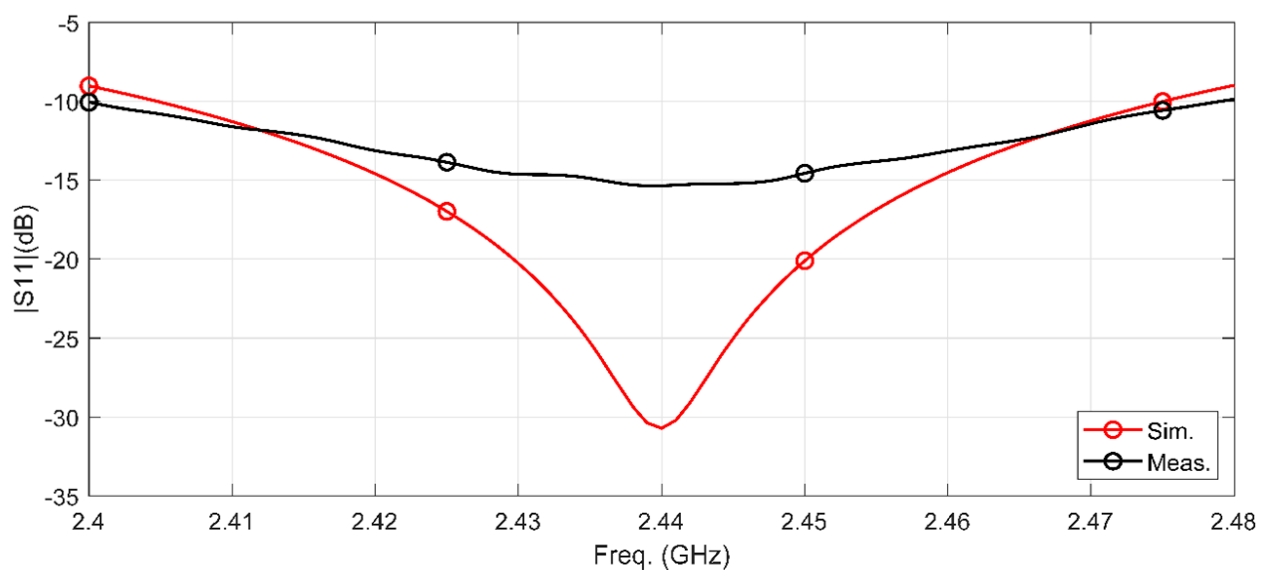
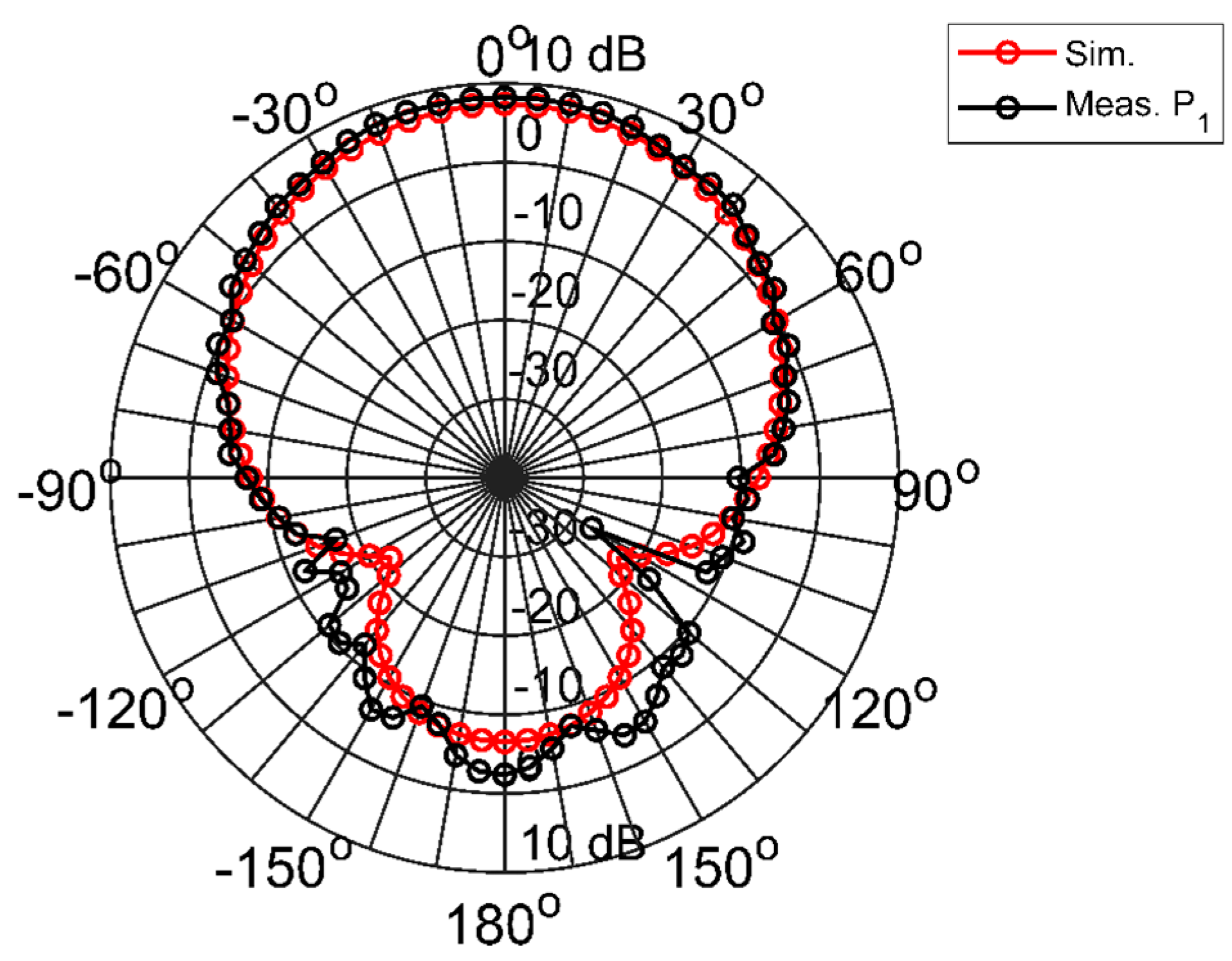
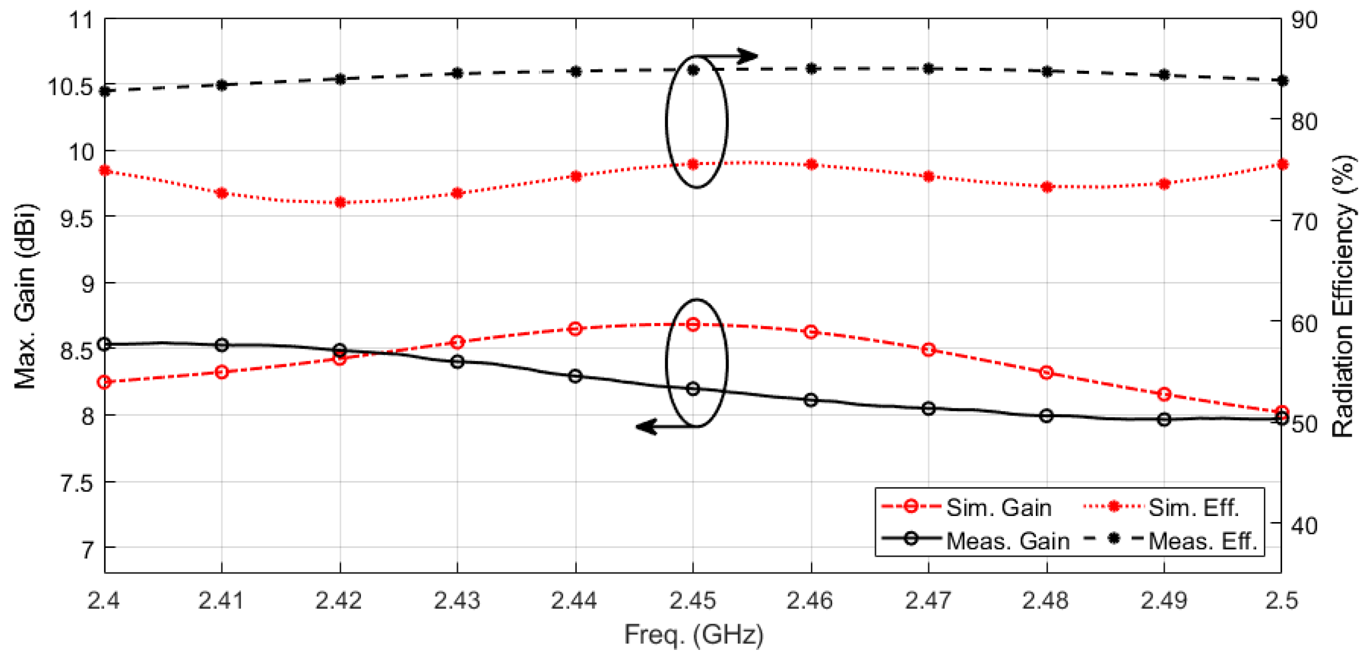
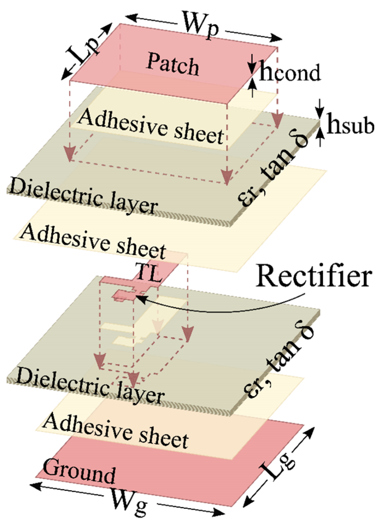
2.1. Antenna Design
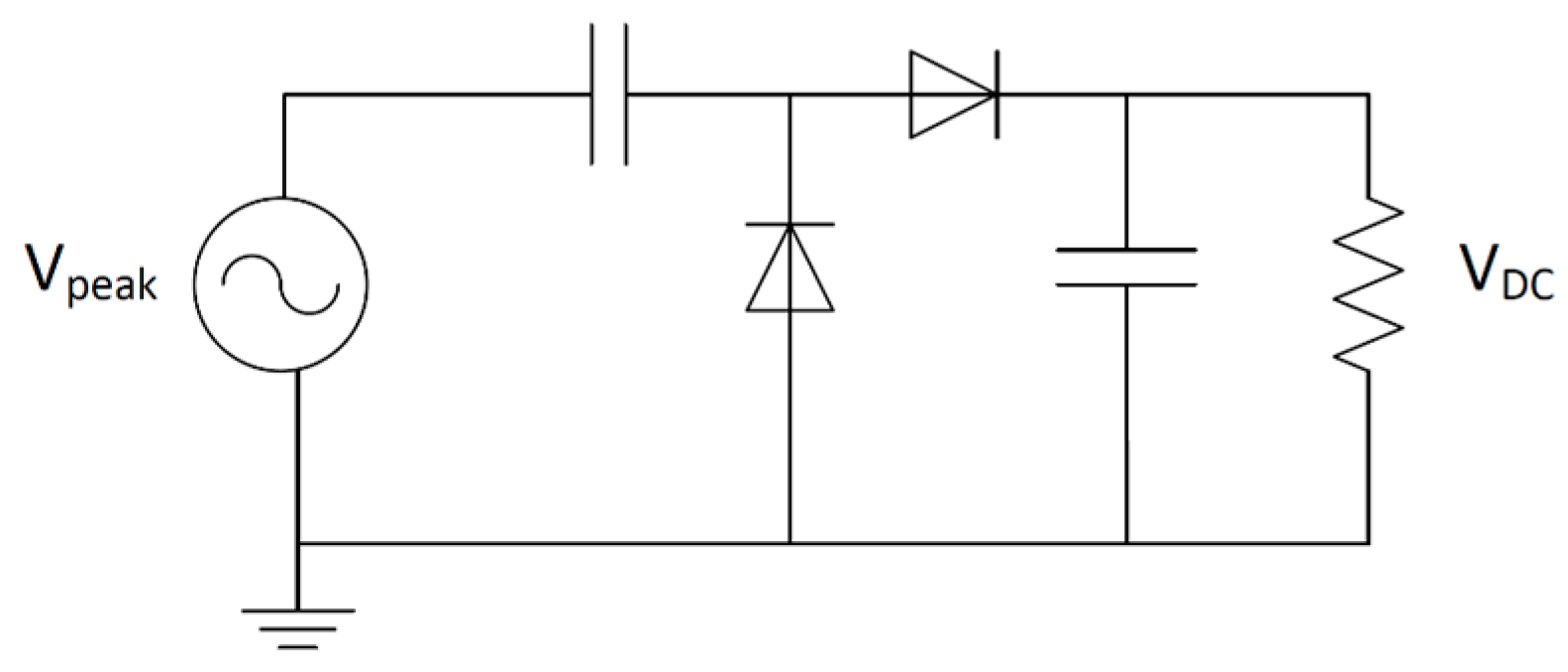
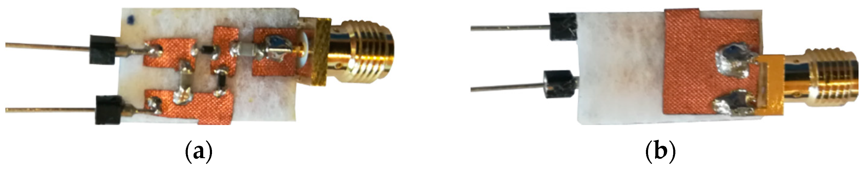
2.2. Rectifier Design
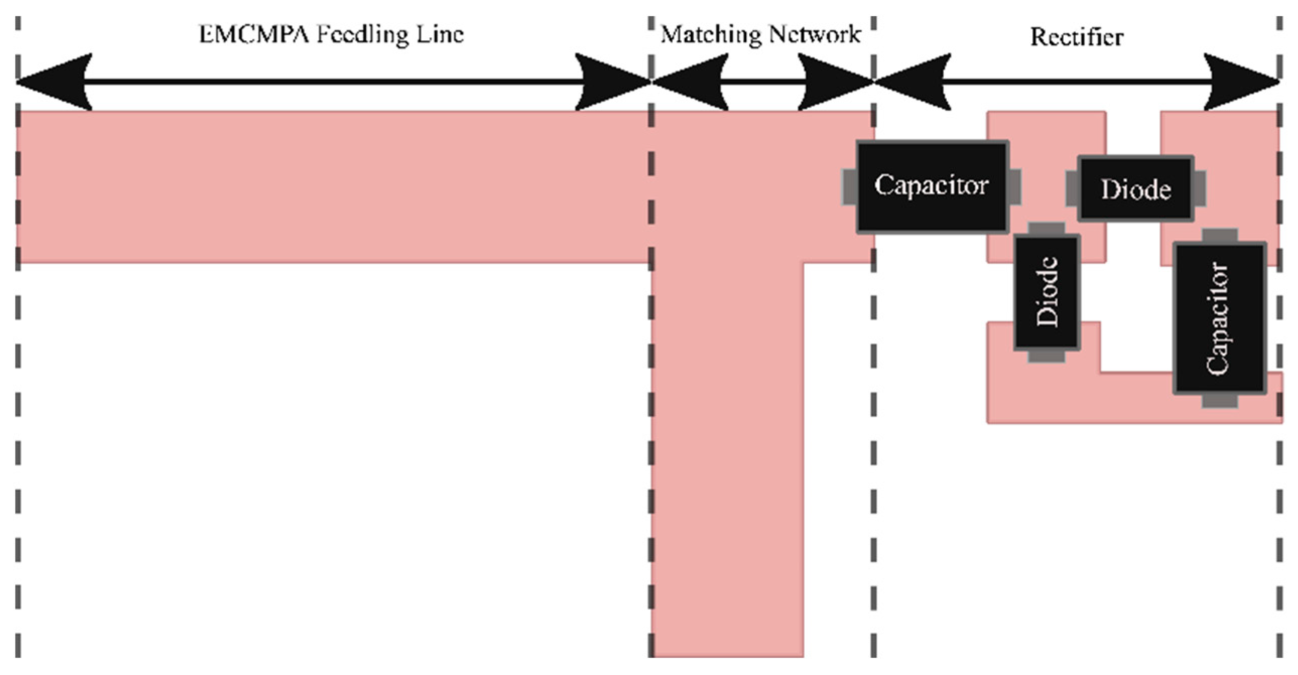
2.3. Rectenna Integration
3. Single Rectenna Measurements
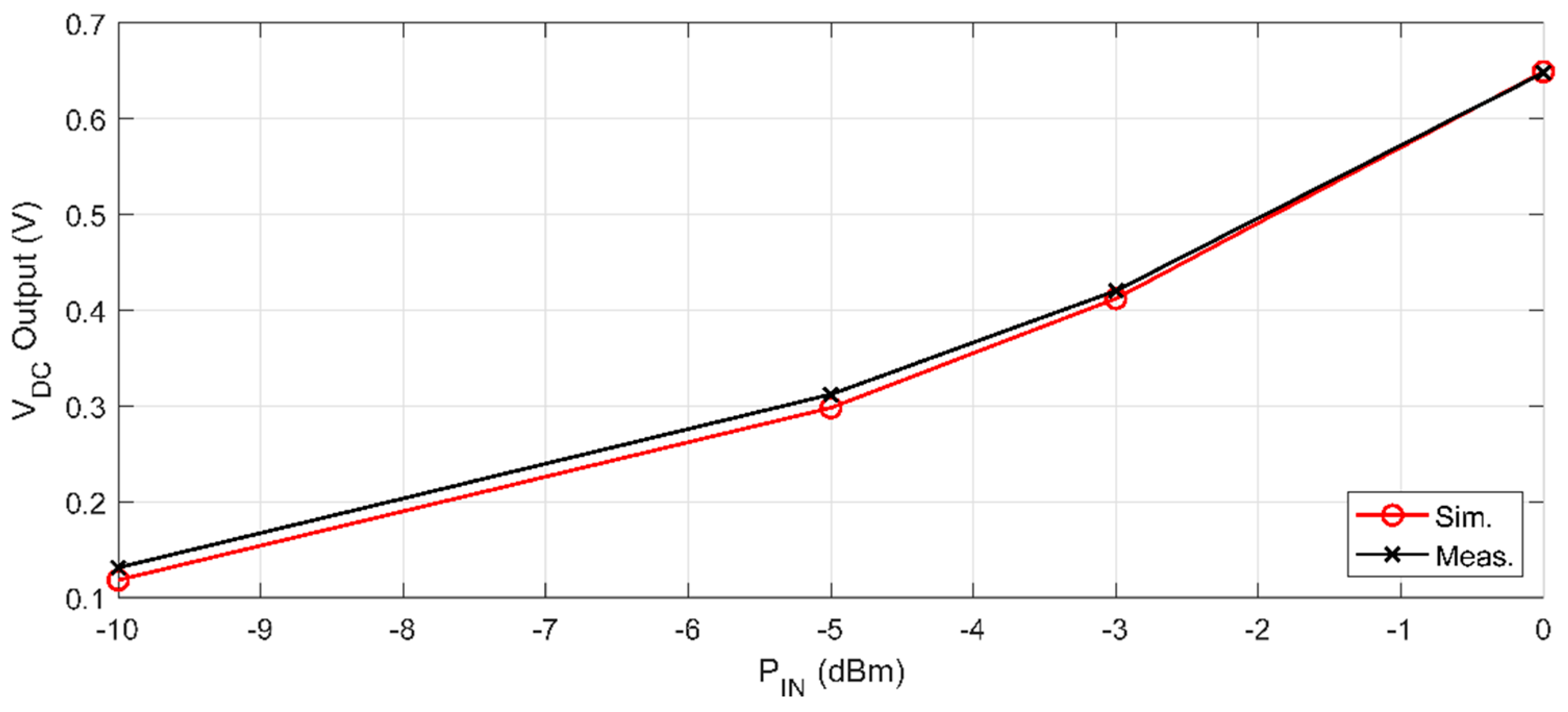
3.1. Rectifier Input Power Configuration
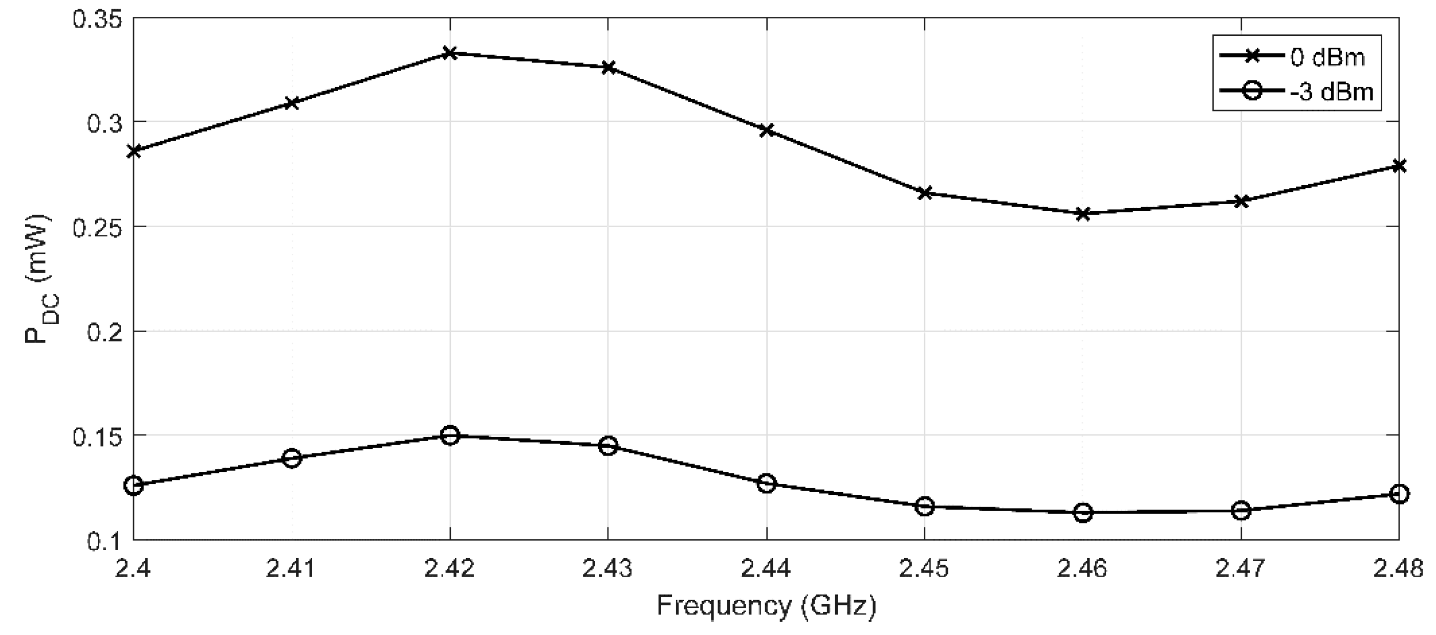
3.2. Individual Rectenna PCE Measurements
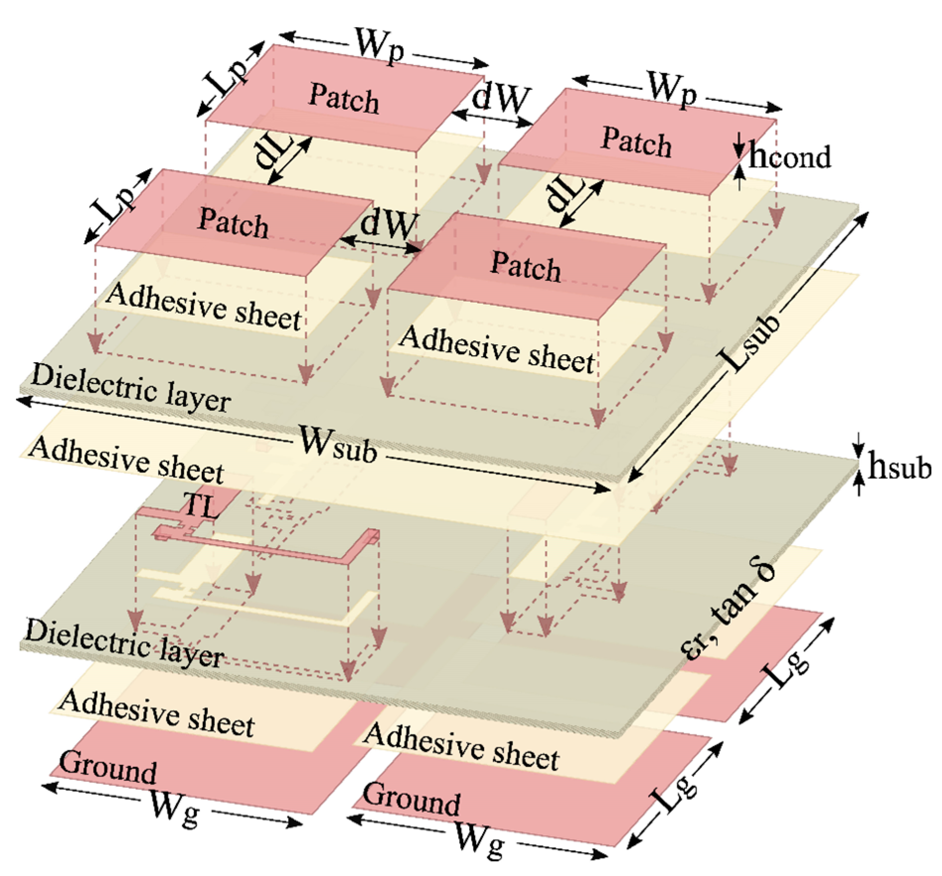
4. Rectenna Array Configuration
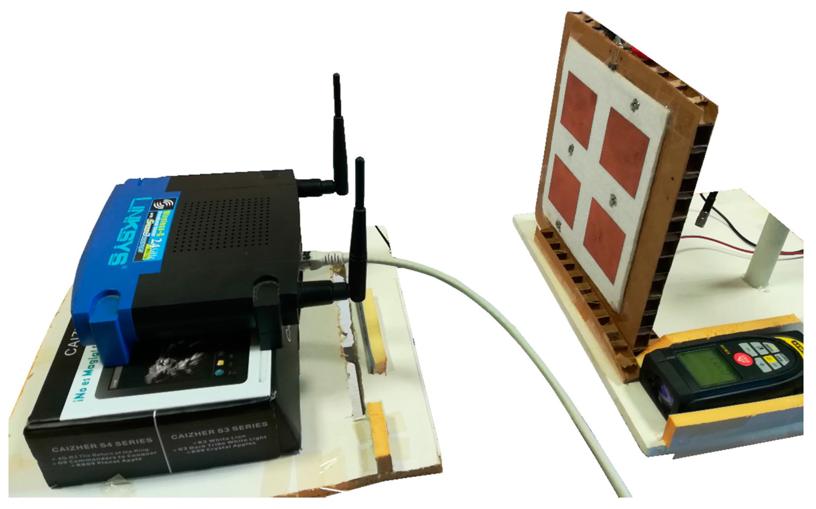
5. Array Measurements
6. Conclusions
Author Contributions
Funding
Acknowledgments
Conflicts of Interest
References
- Stoppa, M.; Chiolerio, A. Wearable Electronics and Smart Textiles: A Critical Review. Sensors 2014, 14. [Google Scholar] [CrossRef] [PubMed] [Green Version]
- Yang, K.; Isaia, B.; Brown, L.J.E.; Beeby, S. E-Textiles for Healthy Ageing. Sensors 2019, 19, 4463. [Google Scholar] [CrossRef] [Green Version]
- Feito, Y.; Moriarty, T.A.; Mangine, G.; Monahan, J. The use of a smart-textile garment during high-intensity functional training: A pilot study. J. Sports Med. Phys. Fit. 2019, 59, 947–954. [Google Scholar] [CrossRef] [PubMed]
- Schmitz, B.; Hofmann, C.; Maestre, R.; Bleda, A.L.; Tobola, A.; Melcher, V.; van Gent, J. Continuous vital monitoring and automated alert message generation for motorbike riders. In Proceedings of the 2015 Computing in Cardiology Conference (CinC), Nice, France, 6–9 September 2015; pp. 397–400. [Google Scholar]
- Nayak, R.; Wang, L.; Padhye, R. 11—Electronic textiles for military personnel. In Electronic Textiles; Dias, T., Ed.; Woodhead Publishing: Oxford, UK, 2015; pp. 239–256. [Google Scholar]
- Chen, D.; Lawo, M. Smart Textiles and Smart Personnel Protective Equipment. In Smart Textiles: Fundamentals, Design, and Interaction; Schneegass, S., Amft, O., Eds.; Springer International Publishing: Cham, Switzerland, 2017; pp. 333–357. [Google Scholar]
- Peppler, K. STEAM-Powered Computing Education: Using E-Textiles to Integrate the Arts and STEM. Computer 2013, 46, 38–43. [Google Scholar] [CrossRef]
- Jaquard by Google Weaves New Digital Experiences into the Things You Love, Wear, and Use Every Day to Give You the Power to Do More and Be More. Available online: https://atap.google.com/jacquard/ (accessed on 22 January 2020).
- Brown, W.C. The History of Power Transmission by Radio Waves. IEEE Trans. Microw. Theory Tech. 1984, 32, 1230–1242. [Google Scholar] [CrossRef] [Green Version]
- Tran, L.-G.; Cha, H.-K.; Park, W.-T. RF power harvesting: A review on designing methodologies and applications. Micro Nano Syst. Lett. 2017, 5, 14. [Google Scholar] [CrossRef] [Green Version]
- Visser, H.J.; Vullers, R.J.M. RF Energy Harvesting and Transport for Wireless Sensor Network Applications: Principles and Requirements. Proc. IEEE 2013, 101, 1410–1423. [Google Scholar] [CrossRef]
- Soyata, T.; Copeland, L.; Heinzelman, W. RF Energy Harvesting for Embedded Systems: A Survey of Tradeoffs and Methodology. IEEE Circuits Syst. Mag. 2016, 16, 22–57. [Google Scholar] [CrossRef]
- Piñuela, M.; Mitcheson, P.D.; Lucyszyn, S. Ambient RF Energy Harvesting in Urban and Semi-Urban Environments. IEEE Trans. Microw. Theory Tech. 2013, 61, 2715–2726. [Google Scholar] [CrossRef]
- Chiaramello, E.; Bonato, M.; Fiocchi, S.; Tognola, G.; Parazzini, M.; Ravazzani, P.; Wiart, J. Radio Frequency Electromagnetic Fields Exposure Assessment in Indoor Environments: A Review. Int. J. Environ. Res. Public Health 2019, 16, 955. [Google Scholar] [CrossRef] [Green Version]
- Carvalho, N.B.; Georgiadis, A.; Costanzo, A.; Rogier, H.; Collado, A.; García, J.A.; Lucyszyn, S.; Mezzanotte, P.; Kracek, J.; Masotti, D.; et al. Wireless Power Transmission: R&D Activities within Europe. IEEE Trans. Microw. Theory Tech. 2014, 62, 1031–1045. [Google Scholar] [CrossRef]
- Valenta, C.R.; Durgin, G.D. Harvesting Wireless Power: Survey of Energy-Harvester Conversion Efficiency in Far-Field, Wireless Power Transfer Systems. IEEE Microw. Mag. 2014, 15, 108–120. [Google Scholar] [CrossRef]
- Olgun, U.; Chen, C.; Volakis, J.L. Investigation of Rectenna Array Configurations for Enhanced RF Power Harvesting. IEEE Antennas Wirel. Propag. Lett. 2011, 10, 262–265. [Google Scholar] [CrossRef]
- Khang, S.; Lee, D.; Hwang, I.; Yeo, T.; Yu, J. Microwave Power Transfer with Optimal Number of Rectenna Arrays for Midrange Applications. IEEE Antennas Wirel. Propag. Lett. 2018, 17, 155–159. [Google Scholar] [CrossRef]
- Popović, Z.; Korhummel, S.; Dunbar, S.; Scheeler, R.; Dolgov, A.; Zane, R.; Falkenstein, E.; Hagerty, J. Scalable RF Energy Harvesting. IEEE Trans. Microw. Theory Tech. 2014, 62, 1046–1056. [Google Scholar] [CrossRef]
- Chuma, E.L.; Rodríguez, L.d.l.T.; Iano, Y.; Roger, L.L.B.; Sanchez-Soriano, M.-A. Compact rectenna based on a fractal geometry with a high conversion energy efficiency per area. IET Microw. Antennas Propag. 2018, 12, 173–178. [Google Scholar] [CrossRef]
- Estrada, J.A.; Kwiatkowski, E.; López-Yela, A.; Borgoñós-García, M.; Segovia-Vargas, D.; Barton, T.; Popović, Z. RF-Harvesting Tightly Coupled Rectenna Array Tee-Shirt with Greater than Octave Bandwidth. IEEE Trans. Microw. Theory Tech. 2020, 68, 3908–3919. [Google Scholar] [CrossRef]
- Monti, G.; Corchia, L.; Tarricone, L. UHF Wearable Rectenna on Textile Materials. IEEE Trans. Antennas Propag. 2013, 61, 3869–3873. [Google Scholar] [CrossRef]
- Adami, S.; Zhu, D.; Yi, L.; Mellios, E.; Stark, B.H.; Beeby, S. A 2.45 GHz rectenna screen-printed on polycotton for on-body RF power transfer and harvesting. In Proceedings of the 2015 IEEE Wireless Power Transfer Conference (WPTC), Boulder, CO, USA, 13–15 May 2015; pp. 1–4. [Google Scholar]
- Adami, S.E.; Proynov, P.; Hilton, G.S.; Yang, G.; Zhang, C.; Zhu, D.; Li, Y.; Beeby, S.P.; Craddock, I.J.; Stark, B.H. A Flexible 2.45-GHz Power Harvesting Wristband with Net System Output from −24.3 dBm of RF Power. IEEE Trans. Microw. Theory Tech. 2018, 66, 380–395. [Google Scholar] [CrossRef] [Green Version]
- Vital, D.; Bhardwaj, S.; Volakis, J.L. Textile-Based Large Area RF-Power Harvesting System for Wearable Applications. IEEE Trans. Antennas Propag. 2020, 68, 2323–2331. [Google Scholar] [CrossRef]
- Wagih, M.; Weddell, A.S.; Beeby, S. Omnidirectional Dual-Polarized Low-Profile Textile Rectenna with Over 50% Efficiency for Sub-μW/cm2 Wearable Power Harvesting. IEEE Trans. Antennas Propag. 2021, 69, 2522–2536. [Google Scholar] [CrossRef]
- Wagih, M.; Hilton, G.S.; Weddell, A.S.; Beeby, S. Dual-Band Dual-Mode Textile Antenna/Rectenna for Simultaneous Wireless Information and Power Transfer (SWIPT). IEEE Trans. Antennas Propag. 2021, 1. [Google Scholar] [CrossRef]
- Del-Rio-Ruiz, R.; Lopez-Garde, J.M.; Legarda, J.; Caytan, O.; Rogier, H. A Combination of Transmission Line Models as Design Instruments for Electromagnetically Coupled Microstrip Patch Antennas in the 2.45 GHz ISM Band. IEEE Trans. Antennas Propag. 2021, 69, 550–555. [Google Scholar] [CrossRef]
- Del-Rio-Ruiz, R.; Lopez-Garde, J.; Legarda, J.; Lemey, S.; Caytan, O.; Rogier, H. Reliable Lab-Scale Construction Process for Electromagnetically Coupled Textile Microstrip Patch Antennas for the 2.45 GHz ISM Band. IEEE Antennas Wirel. Propag. Lett. 2020, 19, 153–157. [Google Scholar] [CrossRef]
- Duffy, S.M. An enhanced bandwidth design technique for electromagnetically coupled microstrip antennas. IEEE Trans. Antennas Propag. 2000, 48, 161–164. [Google Scholar] [CrossRef]
- Soh, P.J.; Vandenbosch, G.A.E.; Ooi, S.L.; Rais, N.H.M. Design of a Broadband All-Textile Slotted PIFA. IEEE Trans. Antennas Propag. 2012, 60, 379–384. [Google Scholar] [CrossRef]
- Simorangkir, R.B.V.B.; Yang, Y.; Matekovits, L.; Esselle, K.P. Dual-Band Dual-Mode Textile Antenna on PDMS Substrate for Body-Centric Communications. IEEE Antennas Wirel. Propag. Lett. 2017, 16, 677–680. [Google Scholar] [CrossRef]
- Depret, D.; Rogier, H.; Dhaenens, K.; Vanfleteren, J. Flexible-substrate low-cost construction of a coplanar-waveguide aperture-coupled microstrip patch antenna. Microw. Opt. Technol. Lett. 2007, 49, 1071–1074. [Google Scholar] [CrossRef] [Green Version]
- Lorenz, C.H.P.; Hemour, S.; Wu, K. Physical Mechanism and Theoretical Foundation of Ambient RF Power Harvesting Using Zero-Bias Diodes. IEEE Trans. Microw. Theory Tech. 2016, 64, 2146–2158. [Google Scholar] [CrossRef]
- Sun, H.; Geyi, W. A New Rectenna with All-Polarization-Receiving Capability for Wireless Power Transmission. IEEE Antennas Wirel. Propag. Lett. 2016, 15, 814–817. [Google Scholar] [CrossRef]


| Ref. | Freq. (GHz) | Material | Antenna | Rectifier | Array | |||||||
|---|---|---|---|---|---|---|---|---|---|---|---|---|
| Conductive | Dielectric | Topology | Construction | Gain 1 (dBi) | Topology | Diode | Eff (%) | CE 1 (%) | CEmax 1 (%) | Array | ||
| [22] | 0.9 | Nylon Copper Fabric | Jeans | Microstrip | Glue | 4.6 | Full Wave Bridge | HSMS285X | NA | 20 | 50 | NO |
| [23] | 2.45 | Silver Ink | PES/Cotton | Microstrip | Screen printing | NA | Voltage Doubler | NA | NA | NA | NA | NO |
| [24] | 2.45 | Polyester Copper Fabric | PES/Felt | EMCMPA | Glue | 8.1 | Single | SMS7630 | 65 | NA | 29 | YES |
| [21] | 2–5 | Metallized ink | Cotton | Bowtie | Screen printing | NA | Single | SMS7630 | NA | 17 | 32 | YES |
| [25] | 2.45 | Thread | Organza | Microstrip | Embroidery | 6.5 | Single | SMS7630 | 60 | NA | NA | YES |
| Own | 2.40–2.48 | PCPTF | Felt | EMCMPA | Glue | 8.2 | Voltage Doubler | SMS7630 | 56 | 31 | 38 | YES |
| Wp | Lp | Wg | Lg | Wsub | Lsub | Wline | Lline |
|---|---|---|---|---|---|---|---|
| 57.96 | 51.10 | 72.36 | 65.50 | 84.36 | 77.50 | 10.4 | 27.75 |
| PTX (dBm) | G (dBi) | S11 (dB) | ℘RX (μW/cm2) | PRX (dBm) | Distance (m) |
|---|---|---|---|---|---|
| +12 | 7.8 | −12.6 | 14 | +0 | 0.21 |
| PTX (dBm) | ℘RXavg (μW/cm2) | PDCmax (mW) | PDCavg (mW) | PCEmax (%) | PCEavg (%) |
|---|---|---|---|---|---|
| +9 | 7 | 0.087 | 0.072 | 26 | 19 |
| +12 | 14 | 0.261 | 0.207 | 38 | 29 |
| PTX (dBm) | ℘RXavg (μW/cm2) | PDCmax (mW) | PDCavg (mW) | PCEmax (%) | PCEavg (%) |
|---|---|---|---|---|---|
| +9 | 7 | 0.431 | 0.358 | 26 | 21 |
| +12 | 14 | 1.281 | 1.068 | 38 | 31 |
| PTX (dBm) | ℘RXavg (μW/cm2) | PDCmax (mW) | PDCavg (mW) | PCEmax (%) | PCEavg (%) |
|---|---|---|---|---|---|
| +9 | 7 | 0.437 | 0.323 | 27 | 19 |
| +12 | 14 | 1.287 | 0.988 | 40 | 29 |
| PTX (dBm) | ℘RXavg (μW/cm2) | Angle (°) | PDCmax (mW) | PDCavg (mW) | PCEmax (%) | PCEavg (%) |
|---|---|---|---|---|---|---|
| 0 | 1.281 | 1.068 | 0.38 | 0.31 | ||
| +12 | 14 | 30 | 0.888 | 0.703 | 0.26 | 0.20 |
| 45 | 0.460 | 0.350 | 0.14 | 0.10 | ||
| 0 | 0.431 | 0.358 | 0.26 | 0.21 | ||
| +9 | 7 | 30 | 0.275 | 0.220 | 0.17 | 0.13 |
| 45 | 0.126 | 0.097 | 0.08 | 0.06 | ||
| 9 | 0.154 | 0.125 | 0.19 | 0.14 | ||
| +6 | 3.5 | 30 | 0.088 | 0.070 | 0.11 | 0.08 |
| 45 | 0.036 | 0.027 | 0.04 | 0.03 |
Publisher’s Note: MDPI stays neutral with regard to jurisdictional claims in published maps and institutional affiliations. |
© 2021 by the authors. Licensee MDPI, Basel, Switzerland. This article is an open access article distributed under the terms and conditions of the Creative Commons Attribution (CC BY) license (https://creativecommons.org/licenses/by/4.0/).
Share and Cite
Lopez-Garde, J.-M.; Del-Rio-Ruiz, R.; Legarda, J.; Rogier, H. 2 × 2 Textile Rectenna Array with Electromagnetically Coupled Microstrip Patch Antennas in the 2.4 GHz WiFi Band. Electronics 2021, 10, 1447. https://doi.org/10.3390/electronics10121447
Lopez-Garde J-M, Del-Rio-Ruiz R, Legarda J, Rogier H. 2 × 2 Textile Rectenna Array with Electromagnetically Coupled Microstrip Patch Antennas in the 2.4 GHz WiFi Band. Electronics. 2021; 10(12):1447. https://doi.org/10.3390/electronics10121447
Chicago/Turabian StyleLopez-Garde, Juan-Manuel, Ruben Del-Rio-Ruiz, Jon Legarda, and Hendrik Rogier. 2021. "2 × 2 Textile Rectenna Array with Electromagnetically Coupled Microstrip Patch Antennas in the 2.4 GHz WiFi Band" Electronics 10, no. 12: 1447. https://doi.org/10.3390/electronics10121447