Article

Development of Soft Composite Based Anisotropic Synthetic Skin for Biomechanical Testing

1
Centre for Biomedical Engineering, Indian Institute of Technology (IIT), Delhi 110016, India
2
Department of Biomedical Engineering, All India Institute of Medical Sciences (AIIMS), Delhi 110029, India
*
Author to whom correspondence should be addressed.
Fibers 2023, 11(6), 55; https://doi.org/10.3390/fib11060055
Submission received: 1 April 2023 / Revised: 5 June 2023 / Accepted: 14 June 2023 / Published: 16 June 2023

Abstract

:
Human skin exhibits highly varying mechanical properties, thickness, hardness, and anisotropy by virtue of changing fiber distributions and orientations, across different body locations. To date, only a few studies have computationally simulated skin anisotropy and no experimental study on synthetic skin exists which can mimic the accurate biomechanical properties of the skin. In this work, unique anisotropic synthetic skin samples were created using an elastic composite-based structure. Both single and multi-layer synthetic skin were fabricated with consistent fiber density and fiber dimensions and varying fiber angles to generate over 100 compositions. The compositions implied stress versus stretch responses in mechanical biaxial testing were compared to those of the skin of a person. Hyperelastic constitutive models were used to characterize the non-uniform test results. The created anisotropic synthetic skin must be essential for reliable Biomechanical investigation of skin free from ethical concerns, undertaking medical training and researching skin pathophysiology and injuries.

1. Introduction

Soft tissues that are anisotropic and heterogeneous include muscles, tissues, organs (such as the brain), and the skin [1,2,3]. These types of tissues exhibit anisotropy in all three dimensions, specifically directional anisotropy [3,4]. Variations in the composition of collagen fibres in tissues are considered to be the fundamental contributor to material anisotropy [5]. Histological examinations were utilized in the past for the purpose of researching the arrangement of collagen fibers in different tissues [5,6]. To date, only a few attempts have been made within the published research [6,7,8,9,10,11] to incorporate tissue or soft material anisotropy into computer and experimental models. In order to approximate a major fiber path, the most common method has been to separate the tissues into areas (i.e., each area marked with a unique fiber orientation) and then estimate the average path [6,12]. Allocating a stiffer or harder material property to a major fiber orientation can be conducted through a variety of passive excitation techniques [13,14,15]. Researchers studying traumatic brain injury (TBI) have lately adopted methods for simulating tissues with anisotropic materials in order to enhance the biofidelity and accuracy of numerical simulations [1,16]. Researchers have also focused on white matter in the brain from a tissue anisotropy standpoint due to the coherent orientation of fibers [16,17,18,19]. Recently, Singh et al. [12] developed an artificial skin with different hardness levels. A polymeric material with isotropic properties was utilized to create various synthetic skin compositions and aimed at mimicking the approximate mechanical characteristics of anisotropic human skin found in different areas of the body.
Anisotropy and orthotropy have been measured through experiments in a variability of soft material or tissues, involving the skin, pelvis, and brain [16,20,21]. Porcine skin has also been subjected to tensile testing till rupture to determine the susceptibility of skin resistance and fracture-associated parameters to directional changes [22,23]. Its elastic modulus and fracture strength were found to change dramatically depending on the orientation of the tissue [22]. Differences in collagen composition and structure may also contribute to the age-related sensitivity of skin’s biomechanical properties [23,24]. It has been also observed that tendons’ elasticity and fracture strength may be influenced by age-related variations in the fraction of collagen fibril cross-sectional area [25,26].
Over a wide range of strain rates, Gupta et al. [27] studied oval-shaped isotropic synthetic skin grafts and analyzed the uniaxial tensile characteristics of human skin and an isotropic synthetic skin. The mechanical response of these composite samples were remarkably matching that of human skin at a test rate of 0.4 mm/s. A similar study on the isotropic synthetic skin was conducted at the same strain rate [12,27,28,29]. In order to manufacture and evaluate synthetic skin a strain rate of roughly 0.8 mm/s, Arm et al. [30] used Polydimethylsiloxane (PDMS) type elastomeric composites inhibiting increasing extents of weak polyester fibers. The resulting stress-to-strain curves looked a lot like those of skin made of parallel fibers. The mechanical characterization of the synthetic skin could not be reliably studied because of the non-uniform angles of the fibers in the simulant. An isotropic silicone-based polymer was created and tested for use in 3D printing by Hossain and Liao et al. [31]. Under repeated strain, the stress vs. strain results looked like skin with fibers in the parallel direction. However, the anisotropy properties of skin were not accounted for in this material modelling. Zhang et al. [32] created nanofibers using elastomeric material and it was tested mechanically at a strain rate of 0.08 mm/s. Despite the fact that anisotropy effect was seen with the nanofiber constructions, it was possible to thoroughly alter the fiber angle variation to learn how it affected the mechanical properties of the model. The current state of skin tissue engineering was examined by MacNeil [33]. Although a variety of skin substitutes were described, their parameters and non-isotropic effect were not elaborated upon biomechanically. Recent research attempted to create a non-isotropic tissue model by bulk-arranging the composites fibers. Researchers looked at how the simulants’ mechanical reaction changed as a function of bulk fiber density [34]. The impact of specific fibers, spacings, and orientations was barely examined. To successfully replicate skin, additional research into modelling the influence of structural features (i.e., fiber orientations) is necessary.
To the present day, there have been only a few studies focusing on the development of anisotropic synthetic skin, and none of them have been subjected to biaxial testing to determine whether or not they can accurately imitate the mechanical properties of body locations. As a part of this research, a material system consisting of soft composites was constructed in order to model anisotropic skin types. Extensive research was conducted to investigate how the orientation of the fibers and the number of layers affect the biomechanical properties of the skin. To accurately define the synthetic skin, Mooney-Rivlin and Yeoh hyperelastic material models were utilized in the characterization process. In the parts that follow, we will go through the many approaches that were used during the manufacturing, evaluation, and assessment of the unique anisotropic synthetic skin, as well as the most important outcomes and conclusions that were reached as a result.

2. Materials and Methods

An elastic composite material was formulated, which mimics the anisotropic parameters of human skin, and will be used in realistic biomechanical testing. The mechanical properties of this soft composite material were characterized in terms of its anisotropy, elasticity, and strength to compare it with that of real human skin. Moreover, the nonlinear mechanical characteristics of the composite material were modelled for use in computational simulations.

2.1. Preparation of Matrix and Fiber Materials

To categorize anisotropic synthetic skin materials, ASTM D2240 standards and Shore (Durometer) hardness scale was applied [35,36]. For the development of the matrix, a two-part polymer with 15 A shore hardness of 1.1 g/cc density and exceptionally soft silicone was used [37]. The PLA mold of fiber and matrix were created in SolidWorks 2020 (Dassault Systemes, Velizy-Villacoublay, France) and fabricated using a 3D-printing. Figure 1 shows the schematic of molds with a 30° fiber orientation. For each test, five test samples with the dimensions of 100 × 100 × 2 mm3 were created by pouring a mixture of components A and B into the mold at a 1:1 ratio of polymeric material. The soft fibers were produced by curing a dual-phase polymeric material with a hardness of 30 A and 1.24 g/cc density in the same mold. The fiber was also put through other tests. Biaxial tests were performed on both test samples, which represented the soft fibers and extremely soft matrix, respectively to understand the effect of orientation. The findings of five matrices and five fibers subjected to biaxial tension are compared with those found in the literature studies [27,38].

2.2. Anisotropic Synthetic Skin Fabrication

2.2.1. Development of Single-Layer Synthetic Skin

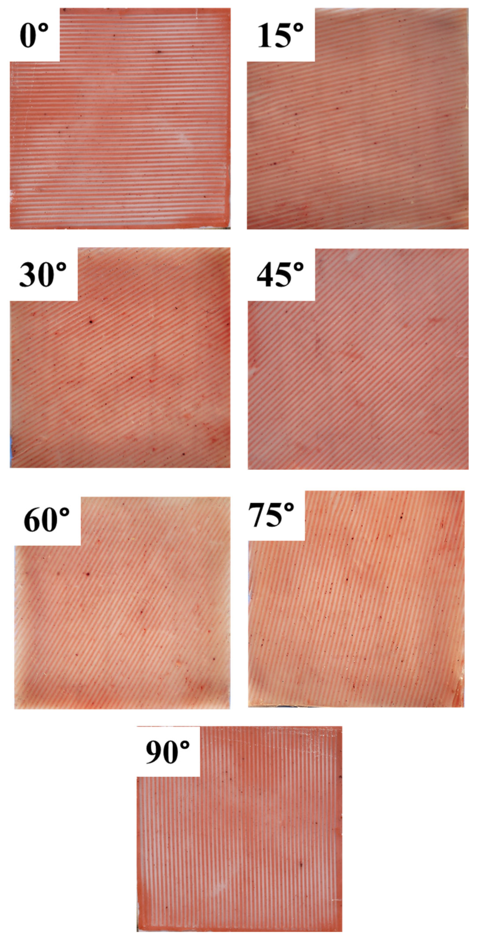
Two separate molds were used to develop the single-layer of synthetic skin with varying fiber angles. The process involved creating the fibers by pouring a polymer that replicated the characteristics of fibers (specifically, one with a shore hardness of 30 A) into a mold with slots capable of accommodating fibers with widths of up to 1 mm. The mixture was left to cure for a duration of 90 min. A square hollowed mold with a little higher surface and an interior thickness of 2 mm was used to hold the part after it had been in the mold for an hour. The matrix indicative polymer (i.e., 15 A shore hardness) was added to the curing combination, which was then permitted 45 min to dry. Whenever the final batch of soft-composite combination was removed from the second mold, the matrix-relevant polymer was poured into it and allowed to cure. In order to imitate every potential orientation of the skin’s fibers, five distinct skin apparition specimens were made. Each specimen was made with fibers that varied in dimension, was positioned 1 mm separated, and had a surface of 1 mm by 1 mm. They all had identical measurements of 100 × 100 × 2 mm3. The varying fiber lengths were brought on by the diverse orientations. Total fiber lengths were 100 mm in the specimens at 0°, but 141.4 mm in the specimens at 45°. The specimens with any of the other available alignments (15°, 30°, 60°, or 75°) had estimated fiber lengths that varied from 2.5 mm to 141.4 mm. To keep the fiber volume percentage roughly constant for all of the varied alignments of the test specimens, a specific fiber spacing and dimension were chosen (Equation (1)). The outcomes of the 0° synthetic skin will be identical to those of the 90° synthetic skin due to the biaxial investigation, it is vital to note. Similarly, the results for 15° and 75° and 30° and 60° were also consistent for this testing (Figure 2). Table 1 shows the fiber and matrix volume fractions of the synthetic skin with varying orientations.
F i b e r   v o l u m e   f r a c t i o n   ( F V F )   =   A r e a   c o v e r e d   b y   f i b e r A r e a   c o v e r e d   b y   f i b e r + A r e a   c o v e r e d   b y   m a t r i x

2.2.2. Development of Multi-Layer Synthetic Skin

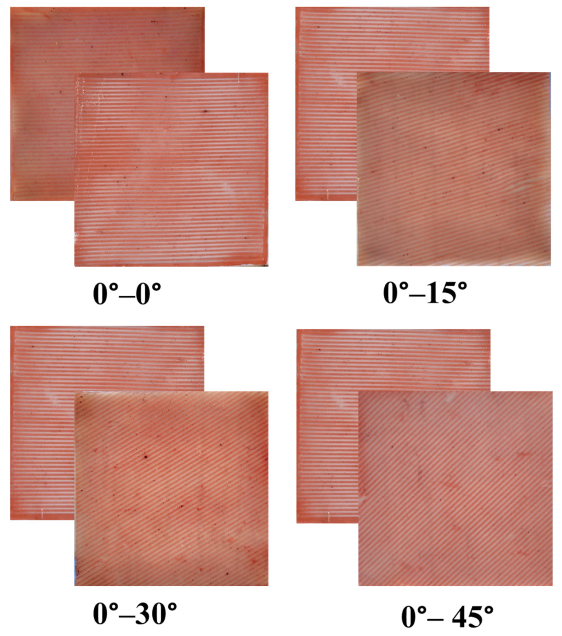
The two-layer skin apparition that was made has external measurements of 100 mm × 100 mm × 3.5 mm. The synthetic skin with layer-wise fiber orientations was also different. Fibers through a consistent area of 1 mm × 1 mm that were stacked twice and divided by a 0.5 mm matrix between the head and base were used to construct the synthetic skin. Three parts of 3D-printed castings were used to create this synthetic skin. Two of these molds had fiber channels that were orientated at different angles, while the third was flat and ordered so that the synthetic skin could be put together layer by layer. The foundation for the bottom-up technique utilized to prepare the subsequent layers was a matrix that was 0.5 mm thicker. In the following steps, single-layer synthetic skin of the first alignment with a thickness of 1 mm, a matrix that was 0.5 mm thicker, single-layer synthetic skin of the second alignment with 1 mm thickness, and a matrix that was 0.5 mm thicker were all added. It is significant to notice the solidifying phase was controlled to ensure that the matrix was distributed evenly throughout the whole construction and that all of the layers had strong links. Figure 3 displays the schematic representation of synthetic skin with two-layers.

2.3. Method Parameters and Testing Setup

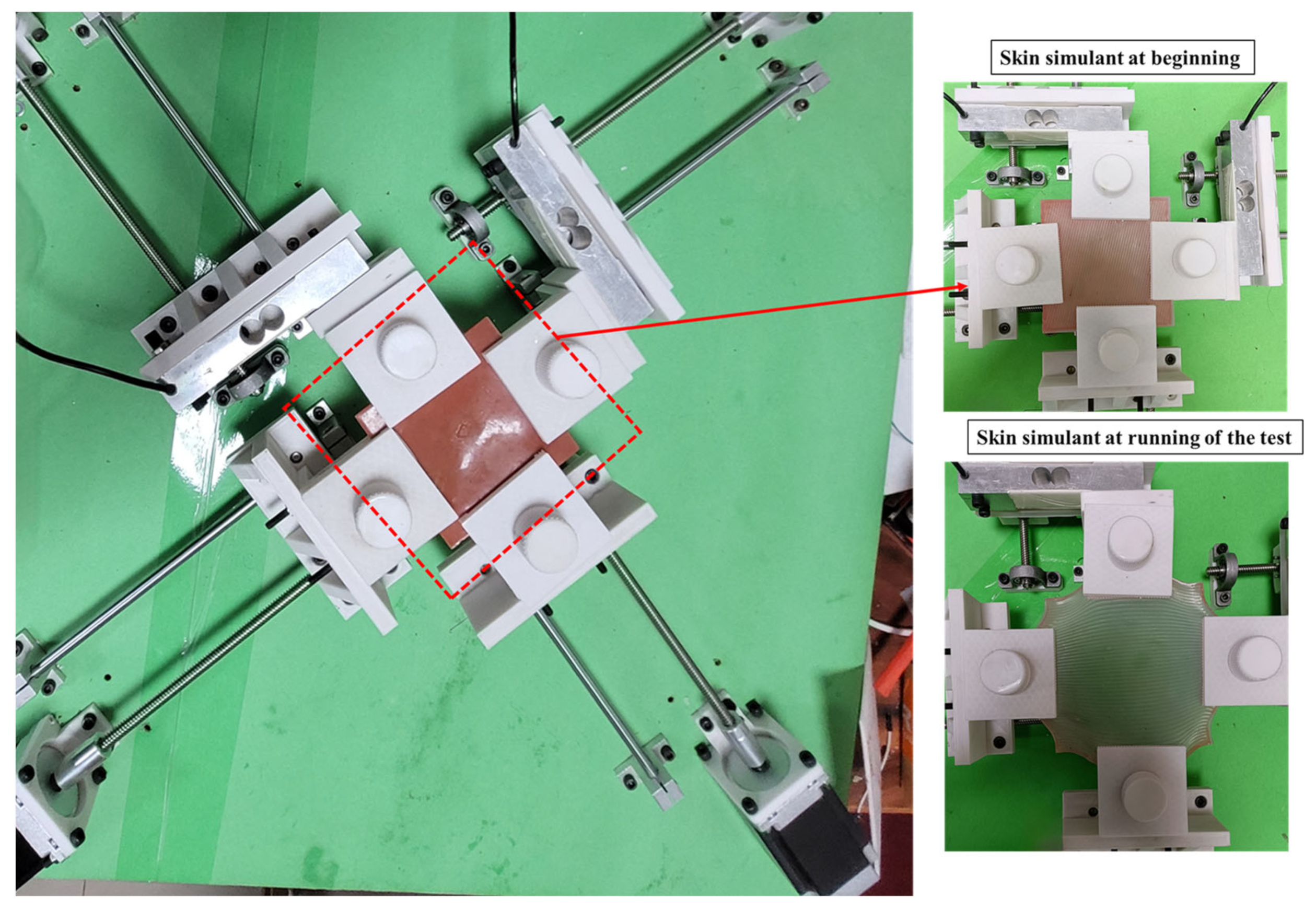
In this work, ASTM standards (ASTM 3787) were used to perform the tensile testing of polymeric material-based compositions were used to analyze the effect of fiber orientations using biaxial testing similar to previous studies [39,40]. Figure 4 displays a design of the biaxial measuring device together with a 40 kg load cell and a gripping mechanism (clamp) that holds onto the 3D-printed component. In order to hold the specimen firmly, a 3D-printed gripper was used. Strong friction and a stable attachment of the sample are made possible by the large number of teeth that are present. To ensure that the sample would be held securely without being harmed, nuts and bolts were attached jointly in the gripper’s cantilever arm. According to the soft tissue, the test sample, and other factors, the minimal amount of gripping power required to firmly attach the sample was varied. An anisotropic synthetic skin biaxial tester was employed for the testing of the sample. The specimen was safely connected among all four biaxial tester clamps. Two loadcells were used to compute the force value data, which was measured by being fastened to the model samples. Equations (2) and (3) were used to determine the amount of stress (σ) and strain (ε), respectively.
Stress   ( σ ) = E q u i v e l e n t   F o r c e   ( F ) C r o s s s e c t i o n   a r e a   ( A ) ,
Strain   ( ε ) = C h a n g e   i n   l e n g t h   ( d L ) I n i t i a l   l e n g t h   ( L )
A constant displacement rate of 0.4 mm/s was applied to each sample while it was clamped and examined [41]. During the process of analyzing the samples, there were a number of considerations that were taken into consideration. We tested both the reproducibility and repeatability of the data from the biaxial tensile experiments. The data show that the force was calculated in newtons (N) and the extension was measured in millimeters (mm). Tables in Microsoft Excel were used to compile the data, which was presented as a comparison of force to elongation. For the purposes of this investigation, the maximum allowable stretch limit was established at 1.5. (i.e., the strain of 0.5). For the postprocessing of the raw data values, a well-defined technique was followed, which comprised four important phases. First, the areas of a plot that showed negative load values (which might have been caused by the loss in the sample at the beginning of the test) and any values that had a strain that was more than 0.5 were eliminated. Second, any graphs that continued past the yield point were eliminated from our analysis since we deemed them to be unrelated to our investigation. The plots were then calibrated, and if necessary, they were reset to the beginning. In the third stage, the strain readings were determined by dividing the stretch values by the initial length. In a similar manner, the equivalent stress values were calculated by dividing the force data values by the sample area. This was conducted in order to acquire values. In the fourth step of the process, the values of the stress values and strain values for each sample were derived from the testing of five other samples that were quite comparable.

2.4. Anisotropic Material Characterization

The stress–strain characteristics of soft tissue and polymer-based materials are nonlinear. It has been noted that the matrix experiences less stress than the fibers. The non-uniform mechanical characteristics of the synthetic skin can be explained using hyperelastic fundamental models. All of the constant coefficients in this work are determined using the Yeoh and Mooney-Rivlin hyperelastic curve fit models ( c 1 , c 2 , and c 3 ). The strain energy density (Ψ) formula, which depends on the type of material, is how non-linear hyperelastic curves operate. In the hyperelastic framework, the Ψ is influenced by the invariants of the Cauchy–Green tensor (I1, I2, and I3) or the principal stretches (λ1, λ2, and λ3), which are also functions of the principal stretches. This relationship is depicted in Equations (4)–(8).
Ψ i s o t r o p i c = Ψ ( I 1 , I 2 , I 3 )
λ = 1 + ε
I 1 = i = 1 3 λ i 2
I 2 = i , j = 1 3 λ i 2 λ j 2   i j
I 3 = i = 1 3 λ i 2
Recent work has been conducted to expect the mechanical characteristic of tissues such as skin using the different hyperelastic models [7,27]. In Equations displayed (9)–(13), the Ψ and stress relationship between the hyperelastic model.
Ψ Y e o h = c 1 ( I 1 3 ) 1 + c 2 ( I 1 3 ) 2 + c 3 ( I 1 3 ) 3
Ψ M o o n e y R i v l i n = c 1 ( I 1 3 ) + c 2 ( I 2 3 )
σ 1 = λ 1 Ψ λ 1 λ 3 Ψ λ 3
σ Y e o h = 2 ( λ 2 1 λ ) ( c 1 + 2 c 2 ( I 1 3 ) + 3 c 3 ( I 1 3 ) 2 )
σ M o o n e y R i v l i n = 2 ( λ 2 1 λ ) ( c 1 + c 2 1 λ )

3. Results and Discussion

The aim of this research is to make a significant contribution to the advancement of a composite material that faithfully reproduces the anisotropic characteristics exhibited by human skin. This is the first biaxial study on anisotropic synthetic skin performed to calculate the results of biomimetic materials accurately. For one layer of synthetic skin, the length, width, and thickness were 100 mm × 100 mm × 2 mm, respectively. For two-layer synthetic skin, the length, width, and thickness were 100 mm × 100 mm × 3.5 mm, respectively.

3.1. Stress Analysis of Single-Layer Synthetic Skin

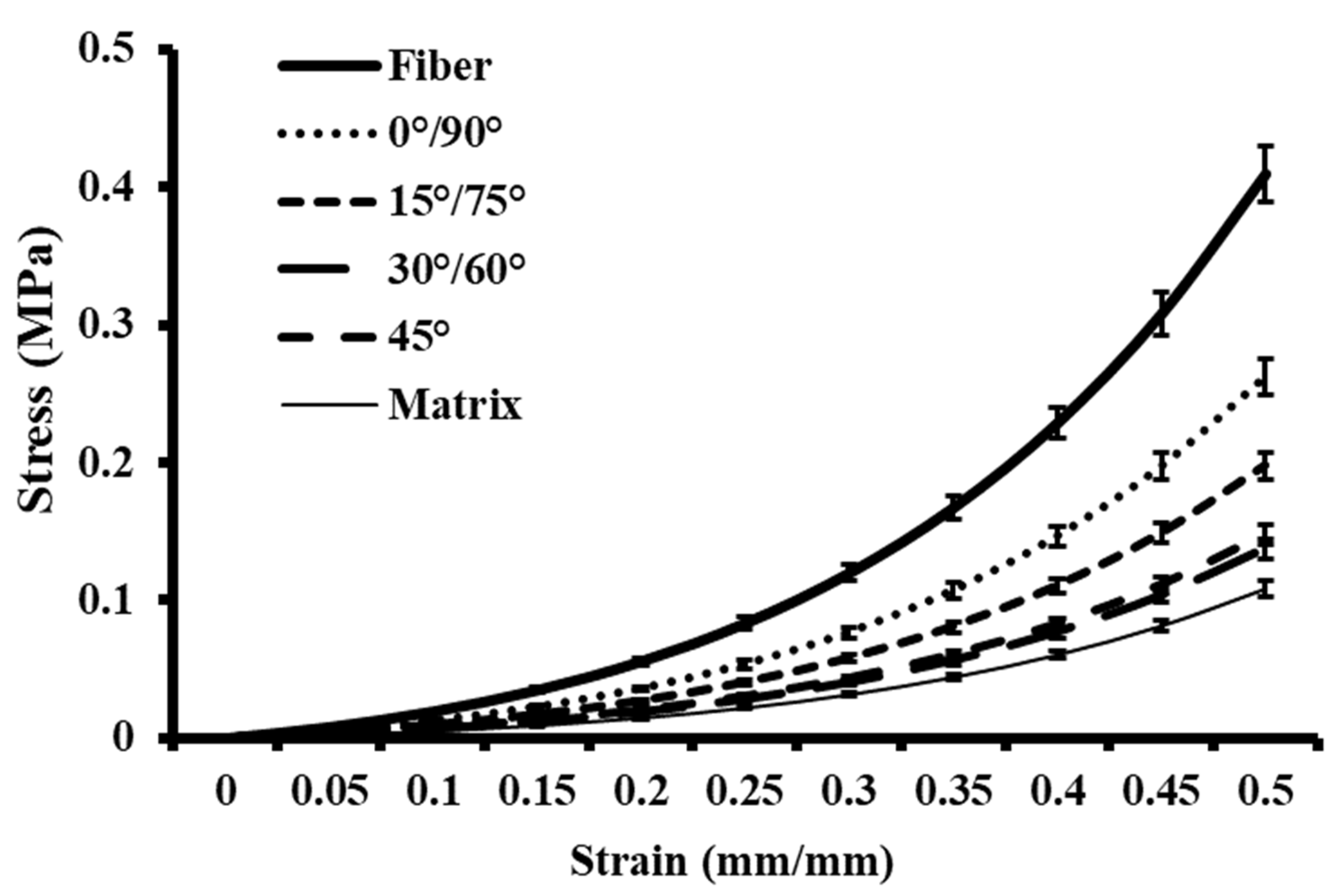
The stress vs. strain characteristics of synthetic skin, consisting of fibers and a matrix, with orientations of 0/90°, 15/75°, 30/60°, and 45°, are presented in Figure 5. To ensure accuracy, each sample underwent five separate examinations. The measurement of each angle was qualified to the direction of the applied force during biaxial loading. The matrix properties were found to be less stiff compared to the properties of the fibers. Furthermore, the synthetic skin composition exhibited lower stiffness compared to the fibers tested individually. The maximum stress values of differently oriented synthetic skin compositions were in between that of the matrix (0.1 MPa) and the fiber (0.4 MPa) materials tested individually. Among the three orientations, the synthetic skin oriented at 30° was recorded to be the softest, with a maximum stress value of 0.13 MPa.
Some of these findings are similar to the observations in conventional polymeric composite tests. For example, the arrangement with all fibers aligned parallel to the loading axis exhibited the highest level of stiffness. However, this stiffness decreased as the angle of the fibers increased. In literature, Chanda et al. [42] fabricated a synthetic skin to model skin wounding and compare it with human skin. The characteristic was performed to estimate the stress–strain responses and wound progression. The stress–strain profile of this isotropic synthetic skin was within the range of properties recorded for the anisotropic synthetic skin compositions developed in the current study. In another study, Chanda et al. [43] conducted an experiment utilizing an isotropic synthetic skin to investigate the impact of injury and suturing, while comparing the properties to that of human skin. In their study, different wounds were created on the polymeric material, and sutures were applied to close the wound. The stress–strain responses were within the range of measurements observed in the current study and the maximum stress values recorded were approximately 0.5 MPa, which closely resembled the properties exhibited by human skin. Recently, Gupta et al. [27] conducted a study where they fabricated synthetic skin grafts using biofidelic materials and examined their mechanical properties in comparison with human skin [27,42,43]. The stress–strain responses and maximum stress values recorded were in line with the results of the current work.

3.2. Stress Analysis of Two-Layer Synthetic Skin

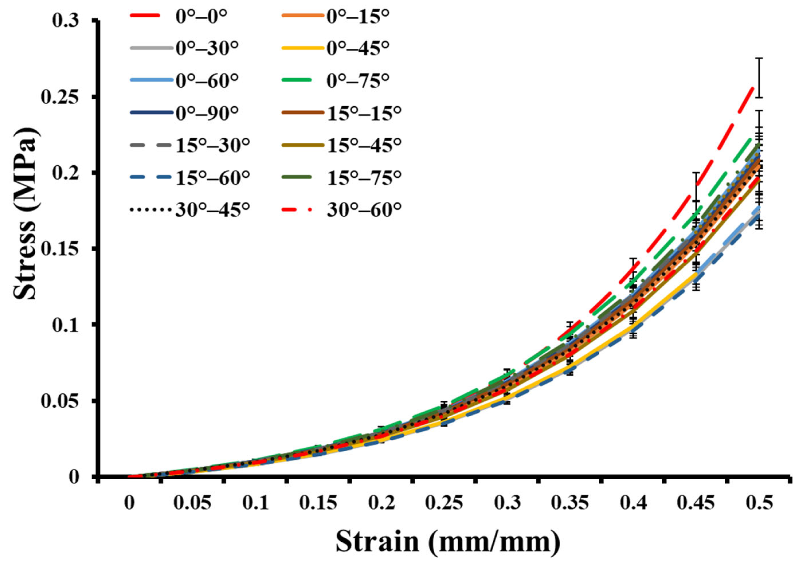
Figure 6 illustrates the two-layer synthetic skin with varied mechanical properties. The 0–0° oriented synthetic skin showed the maximum. However, the stiffness of the 0–15°, 0–30°, 0–45°, 0–60°, 0–75°, and 0–90° angles decreased with increasing angle. With a first layer orientation of 15°, the range of 15° to 60° produced exceptionally soft materials. Other synthetic skin showed stiffness between 0–0° and 15–60°. In the literature, Annaidh et al. [44] conducted a study on the mechanical properties of human skin, performing mechanical tests on various regions of the skin under different strain rates. They conclude that each part of the body location shows a different stiffness and the maximum stress observed by that skin region called ultimate tensile strength (UTS). Each synthetic skin should be further investigated to identify the body location. Singh et al. [12] designed the isotropic synthetic skin with varying the shore hardness based on the body location and studied the mechanical characterization of synthetic skin. From their analysis, the higher shore hardness synthetic skin shows the highest stress values. Overall, all the multi-layer synthetic skin shows slightly different stress distributions due to the orientation of fibers. Further analysis will be useful to develop accurate synthetic skin, including longer lines. Table 2 shows the stress values of the two-layer synthetic skin.

3.3. Hyperelastic Modelling of Synthetic Skin

Equations (12) and (13), which represent the Yeoh hyperelastic and Mooney–Rivlin hyperelastic material modeling, which was used to curve-fit average stress versus stretch graphs for different combinations of single-layer and multi-layer tested synthetic skin. This was conducted in order to determine the relationship between stress and stretch (Table 3). The Yeoh model was dependent on three curve fit parameters (c1, c2 and c3). Mooney–Rivlin model used two curve-fitting parameters (c1, c2). All of the reported Mooney-Rivlin model curve fits had R2 values greater than 0.95. In the case of the Yeoh model, the curve-fitting was, on average, less accurate (that is, R2 was less than 0.95). Overall, all the synthetic skin shows different curve fit coefficients with high co-relation. Further, these results could be used to develop a realistic anisotropic skin model computationally.
Overall, this research was able to lead to the advance of a novel biofidelic material system that accurately replicates the properties of the human skin, allowing for improved biomechanical testing and paving the way for advancements in skin research. To date, no such experimental models exist, which can replicate the uniaxial and biaxial properties of the human skin accurately, without any ethical or biosafety issues.

4. Conclusions

In this work, we tried to make a soft composite-based synthetic skin that acts like skin and has the same anisotropic properties. With the help of additive manufacturing, the novel polymeric material composition was made to make soft fibers and a softer matrix material. The single-layer and multi-layer synthetic skin were developed with different possible orientations. The first type of synthetic skin was a single-layer with different directions of fibers. The second set of skin-like materials consisted of two-layers with fibers arranged at various angles and orientations. In order to concentrate on the impact of fiber orientation, we kept the fiber volume percentage and the spacing across fibers constant. New findings were made that exhibit some similarities to traditional polymer composites while also having a number of distinctive differences. First, the synthetic skin showed a slight association between fiber angle and stiffness. The synthetic skin was more rigid for fiber angles greater than 0°. For the two-layer synthetic skin, a lowering of material inflexibility was seen when the fiber angle of 0° was used in one of the layers. This resulted from a change in the fiber layer orientation. It was discovered that a fiber orientation of 15° in one layer did not generate much of a difference in the stiffness of the material across any fiber layer orientation. It was discovered that a fiber orientation of 30° in a single-layer causes an increase in the stiffness of the material caused by a raise in the fiber angle in the second layer. The strength for various fiber orientations in the second layer did not follow any specific trend when a fiber angle of 45° or higher existed in the first layer. Finally, the mechanical characteristics of the synthetic skin were described with isotropic and anisotropic hyperelastic models, and it was evaluated that they mimic mechanical properties that fall between the range of skin’s upper and lower bounds, as reported in the research. The key novelty of this research is the advancement of an experimental investigation of synthetic skin, which can replicate its realistic anisotropic mechanical properties. Such a synthetic anisotropic skin model, with no ethical or biosafety issues, is not available as a part of any previous literature to the best of our knowledge. Both uniaxial and biaxial tests can be conducted with this novel material. Other applications of this model include surgical training and robotic suture planning.
It is noteworthy that the present work does have a few limitations. The fiber diameters of actual tissues are far smaller than those employed in manufacturing synthetic skin. The most accurate simulation of the material characterization of fibers found in natural tissues was achieved through the utilization of additive manufacturing methods concerning fiber volume fraction. These factors led to the selection of the most optimal dimensions of the fibers for this research, which precisely models the characteristics of fibers found in natural tissues. In order to make accurate comparisons between the study findings and previous research, the dermal layer of skin was the only one that was examined. Throughout all of the experiments, a constant biaxial strain rate was applied. In the future, an attempt will be made to design fiber dimensions that are more realistic and other skin layers will also be taken into consideration. Additionally, developed synthetic skin will be subjected to a variety of strain rates during testing in order to better characterize their properties.
Overall, it is envisaged that the newly discovered anisotropic synthetic skin will be of tremendous use for precise surgical training, biomechanical testing, and the assessment of dermal therapies.

Author Contributions

V.G., R.S. and A.C. contributed substantially to the conception and design of the work; V.G. and R.S. to the acquisition and analysis of the literature; and V.G., G.S. and R.S. to interpretation of data for the work. Additionally, V.G. and R.S. contributed to drafting the work, while V.G., G.S., R.S. and A.C. revised it critically for important intellectual content. All authors have read and agreed to the published version of the manuscript.

Funding

This research received no external funding.

Institutional Review Board Statement

Not applicable.

Informed Consent Statement

Not applicable.

Data Availability Statement

The datasets generated during and/or analyzed during the current study are not publicly available due to large dataset but are available from the corresponding author on reasonable request.

Acknowledgments

This paper and the research would not have been possible without the exceptional support A.C. and facility provided by Indian Institute of Technology Delhi (IIT-D), India.

Conflicts of Interest

The authors declare no conflict of interest.

References

  1. Yi, D.; Choe, Y.M.; Byun, M.S.; Sohn, B.K.; Seo, E.H.; Han, J.; Park, J.; Woo, J.I.; Lee, D.Y. Differences in functional brain connectivity alterations associated with cerebral amyloid deposition in amnestic mild cognitive impairment. Front. Aging Neurosci. 2015, 7, 15. [Google Scholar] [CrossRef] [PubMed]
  2. Picinbono, G.; Delingette, H.; Ayache, N. Non-linear and anisotropic elastic soft tissue models for medical simulation. In Proceedings of the IEEE International Conference on Robotics and Automation, Seoul, Republic of Korea, 21–26 May 2001; Volume 2, pp. 1370–1375. [Google Scholar] [CrossRef]
  3. Singh, G.; Chanda, A. Mechanical properties of whole-body soft human tissues: A review. Biomed. Mater. 2021, 16, 062004. [Google Scholar] [CrossRef] [PubMed]
  4. Serebrakian, A.T.; Pickrell, B.B.; Varon, D.E.; Mohamadi, A.; Grinstaff, M.W.; Rodriguez, E.K.; Nazarian, A.; Halvorson, E.G.; Sinha, I. Meta-analysis and Systematic Review of Skin Graft Donor-site Dressings with Future Guidelines. Plast. Reconstr. Surg. Glob. Open 2018, 6, e1928. [Google Scholar] [CrossRef] [PubMed]
  5. Wong, W.L.E.; Joyce, T.J.; Goh, K.L. Resolving the viscoelasticity and anisotropy dependence of the mechanical properties of skin from a porcine model. Biomech. Model. Mechanobiol. 2016, 15, 433–446. [Google Scholar] [CrossRef]
  6. Flynn, C.; Taberner, A.; Nielsen, P. Mechanical characterisation of in vivo human skin using a 3D force-sensitive micro-robot and finite element analysis. Biomech. Model. Mechanobiol. 2011, 10, 27–38. [Google Scholar] [CrossRef]
  7. Groves, R.B.; Coulman, S.A.; Birchall, J.C.; Evans, S.L. An anisotropic, hyperelastic model for skin: Experimental measurements, finite element modelling and identification of parameters for human and murine skin. J. Mech. Behav. Biomed. Mater. 2013, 18, 167–180. [Google Scholar] [CrossRef]
  8. Roberts, D.E.; Scher, A.M. Effect of tissue anisotropy on extracellular potential fields in canine myocardium in situ. Circ. Res. 1982, 50, 342–351. [Google Scholar] [CrossRef] [Green Version]
  9. Aslanidi, O.V.; Boyett, M.R.; Dobrzynski, H.; Li, J.; Zhang, H. Mechanisms of transition from normal to reentrant electrical activity in a model of rabbit atrial tissue: Interaction of tissue heterogeneity and anisotropy. Biophys. J. 2009, 96, 798–817. [Google Scholar] [CrossRef] [Green Version]
  10. Liu, M.; Wang, L.; Peng, X. Testing, characterizing, and forming of glass twill fabric/polypropylene prepregs. J. Compos. Mater. 2019, 53, 3939–3950. [Google Scholar] [CrossRef]
  11. Mandal, B.B.; Kundu, S.C. Cell proliferation and migration in silk fibroin 3D scaffolds. Biomaterials 2009, 30, 2956–2965. [Google Scholar] [CrossRef]
  12. Singh, G.; Gupta, V.; Chanda, A. Artificial skin with varying biomechanical properties. Mater. Today Proc. 2022, 62, 3162–3166. [Google Scholar] [CrossRef]
  13. Carotenuto, F.; Politi, S.; Ul Haq, A.; De Matteis, F.; Tamburri, E.; Terranova, M.L.; Teodori, L.; Pasquo, A.; Di Nardo, P. From Soft to Hard Biomimetic Materials: Tuning Micro/Nano-Architecture of Scaffolds for Tissue Regeneration. Micromachines 2022, 13, 780. [Google Scholar] [CrossRef]
  14. Patel, S.; Caldwell, J.M.; Doty, S.B.; Levine, W.N.; Rodeo, S.; Soslowsky, L.J.; Thomopoulos, S.; Lu, H.H. Integrating soft and hard tissues via interface tissue engineering. J. Orthop. Res. 2018, 36, 1069–1077. [Google Scholar] [CrossRef] [Green Version]
  15. Michels, J.; Appel, E.; Gorb, S.N. Functional diversity of resilin in Arthropoda. Beilstein J. Nanotechnol. 2016, 7, 1241–1259. [Google Scholar] [CrossRef] [Green Version]
  16. Carlsen, R.W.; Daphalapurkar, N.P. The importance of structural anisotropy in computational models of traumatic brain injury. Front. Neurol. 2015, 6, 28. [Google Scholar] [CrossRef] [Green Version]
  17. Fang, Y.; Yang, X.; Lin, Y.; Shi, J.; Prominski, A.; Clayton, C.; Ostroff, E.; Tian, B. Dissecting Biological and Synthetic Soft-Hard Interfaces for Tissue-Like Systems. Chem. Rev. 2022, 122, 5233–5276. [Google Scholar] [CrossRef]
  18. Liu, Z.; Liao, Z.; Wang, D.; Wang, C.; Song, C.; Li, H.; Liu, Y. Recent Advances in Soft Biological Tissue Manipulating Technologies. Chin. J. Mech. Eng. 2022, 35, 89. [Google Scholar] [CrossRef]
  19. Famaey, N.; Sloten, J.V. Soft tissue modelling for applications in virtual surgery and surgical robotics. Comput. Methods Biomech. Biomed. Eng. 2008, 11, 351–366. [Google Scholar] [CrossRef]
  20. Martins, P.; Peña, E.; Calvo, B.; Doblaré, M.; Mascarenhas, T.; Jorge, R.N.; Ferreira, A. Prediction of nonlinear elastic behaviour of vaginal tissue: Experimental results and model formulation. Comput. Methods Biomech. Biomed. Eng. 2010, 13, 327–337. [Google Scholar] [CrossRef]
  21. Natali, A.N.; Pavan, P.G.; Carniel, E.L.; Dorow, C. A transversally isotropic elasto-damage constitutive model for the periodontal ligament. Comput. Methods Biomech. Biomed. Eng. 2003, 6, 329–336. [Google Scholar] [CrossRef]
  22. Ranamukhaarachchi, S.A.; Lehnert, S.; Ranamukhaarachchi, S.L.; Sprenger, L.; Schneider, T.; Mansoor, I.; Rai, K.; Häfeli, U.O.; Stoeber, B. A micromechanical comparison of human and porcine skin before and after preservation by freezing for medical device development. Sci. Rep. 2016, 6, 32074. [Google Scholar] [CrossRef] [PubMed] [Green Version]
  23. Blair, M.J.; Jones, J.D.; Woessner, A.E.; Quinn, K.P. Skin Structure-Function Relationships and the Wound Healing Response to Intrinsic Aging. Adv. Wound Care 2020, 9, 127–143. [Google Scholar] [CrossRef] [PubMed]
  24. Belkoff, S.M.; Haut, R.C. A structural model used to evaluate the changing microstructure of maturing rat skin. J. Biomech. 1991, 24, 711–720. [Google Scholar] [CrossRef] [PubMed]
  25. Thorpe, C.T.; Birch, H.L.; Clegg, P.D.; Screen, H.R.C. The role of the non-collagenous matrix in tendon function. Int. J. Exp. Pathol. 2013, 94, 248–259. [Google Scholar] [CrossRef]
  26. Li, Y.; Fessel, G.; Georgiadis, M.; Snedeker, J.G. Advanced glycation end-products diminish tendon collagen fiber sliding. Matrix Biol. 2013, 32, 169–177. [Google Scholar] [CrossRef]
  27. Gupta, V.; Chanda, A. Biomechanics of skin grafts: Effect of pattern size, spacing and orientation. Eng. Res. Express 2022, 4, 015006. [Google Scholar] [CrossRef]
  28. Payne, T.; Mitchell, S.; Bibb, R.; Waters, M. Initial validation of a relaxed human soft tissue simulant for sports impact surrogates. Procedia Eng. 2014, 72, 533–538. [Google Scholar] [CrossRef] [Green Version]
  29. Shergold, O.A.; Fleck, N.A.; Radford, D. The uniaxial stress versus strain response of pig skin and silicone rubber at low and high strain rates. Int. J. Impact Eng. 2006, 32, 1384–1402. [Google Scholar] [CrossRef]
  30. Arm, R.; Shahidi, A.; Dias, T. Mechanical behaviour of silicone membranes saturated with short strand, loose polyester fibres for prosthetic and rehabilitative surrogate skin applications. Materials 2019, 12, 3647. [Google Scholar] [CrossRef] [Green Version]
  31. Hossain, M.; Liao, Z. An additively manufactured silicone polymer: Thermo-viscoelastic experimental study and computational modelling. Addit. Manuf. 2020, 35, 101395. [Google Scholar] [CrossRef]
  32. Zhang, J.; Keith, A.N.; Sheiko, S.S.; Wang, X.; Wang, Z. To mimic mechanical properties of the skin by inducing oriented nanofiber microstructures in bottlebrush cellulose-graft-diblock copolymer elastomers. ACS Appl. Mater. Interfaces 2021, 13, 3278–3286. [Google Scholar] [CrossRef]
  33. MacNeil, S. Progress and opportunities for tissue-engineered skin. Nature 2007, 445, 874–880. [Google Scholar] [CrossRef]
  34. Chanda, A.; Callaway, C. Tissue anisotropy modeling using soft composite materials. Appl. Bionics Biomech. 2018, 2018, 4838157. [Google Scholar] [CrossRef] [Green Version]
  35. Ojogbo, E.; Tzoganakis, C.; Mekonnen, T.H. Effect of extrusion, batch-mixing, and co-coagulation on the dispersion of CNCs in natural rubber-CNC nanocomposites. Compos. Part A Appl. Sci. Manuf. 2021, 149, 106580. [Google Scholar] [CrossRef]
  36. Mongkolsuttirat, K.; Sanponpute, T. Prototype of Depth Standard for Elastomer Hardness Tester. J. Phys. Conf. Ser. 2018, 1065, 062012. [Google Scholar] [CrossRef]
  37. Durban, M.M.; Lenhardt, J.M.; Wu, A.S.; Small, W.; Bryson, T.M.; Perez-Perez, L.; Nguyen, D.T.; Gammon, S.; Smay, J.E.; Duoss, E.B.; et al. Custom 3D Printable Silicones with Tunable Stiffness. Macromol. Rapid Commun. 2018, 39, 1700563. [Google Scholar] [CrossRef]
  38. Herzberger, J.; Sirrine, J.M.; Williams, C.B.; Long, T.E. Polymer Design for 3D Printing Elastomers: Recent Advances in Structure, Properties, and Printing. Prog. Polym. Sci. 2019, 97, 101144. [Google Scholar] [CrossRef]
  39. Webster, T.; Yao, C.; Hedrick, M.; Pareek, G.; Haleblian, G.; Renzulli, J. Nanostructured polyurethane-poly-lactic- co-glycolic acid scaffolds increase bladder tissue regeneration: An in vivo study. Int. J. Nanomed. 2013, 8, 3285. [Google Scholar] [CrossRef] [Green Version]
  40. Parikh, D.V.; Calamari, T.A.; Sawhney, A.P.S.; Blanchard, E.J.; Screen, F.J.; Myatt, J.C.; Muller, D.H.; Stryjewski, D.D. Thermoformable Automotive Composites Containing Kenaf and Other Cellulosic Fibers. Text. Res. J. 2002, 72, 668–672. [Google Scholar] [CrossRef]
  41. Singh, G.; Gupta, V.; Chanda, A. Mechanical Characterization of Rotating Triangle Shaped Auxetic Skin Graft Simulants. Facta Univ. Ser. Mech. Eng. 2022, 1–16. [Google Scholar] [CrossRef]
  42. Chanda, A.; Upchurch, W. Biomechanical Modeling of Wounded Skin. J. Compos. Sci. 2018, 2, 69. [Google Scholar] [CrossRef] [Green Version]
  43. Chanda, A.; Unnikrishnan, V.; Flynn, Z.; Lackey, K. Experimental study on tissue phantoms to understand the effect of injury and suturing on human skin mechanical properties. Proc. Inst. Mech. Eng. Part H J. Eng. Med. 2017, 231, 80–91. [Google Scholar] [CrossRef] [PubMed]
  44. Ní Annaidh, A.; Bruyère, K.; Destrade, M.; Gilchrist, M.D.; Otténio, M. Characterization of the anisotropic mechanical properties of excised human skin. J. Mech. Behav. Biomed. Mater. 2012, 5, 139–148. [Google Scholar] [CrossRef] [PubMed] [Green Version]
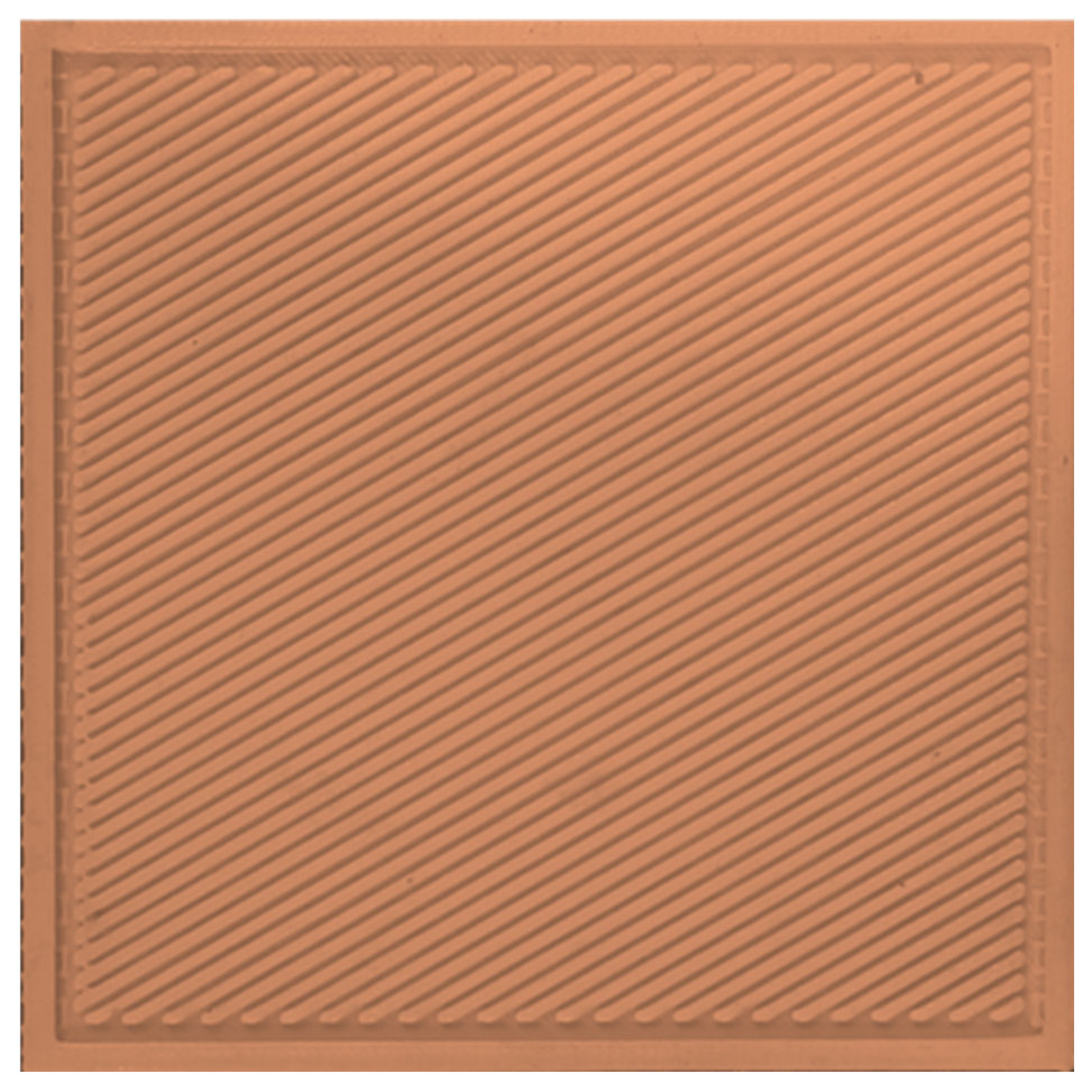
Figure 1. A representative 3D printed mould with 30° fiber alignment.
Fibers 11 00055 g001
Figure 2. Anisotropic synthetic skin with varying fiber angles.
Fibers 11 00055 g002
Figure 3. Representative anisotropic synthetic skin compositions with two-layers that are oriented in different directions.
Fibers 11 00055 g003
Figure 4. Biaxial testing setup with sample at beginning and running stage.
Fibers 11 00055 g004
Figure 5. Stress–strain plots for fiber and matrix tested individually and compared with that of single-layer synthetic skin variants with different fiber orientations.
Fibers 11 00055 g005
Figure 6. Stress–strain plots for two-layer synthetic skin with varying orientations.
Fibers 11 00055 g006
Table 1. Fiber and matrix volume fraction of each synthetic skin.
DesignMatrix Volume (mm3)Fiber Volume (mm3)Fiber Volume FractionMatrix Volume Fraction
0/90°15,18048200.2430.757
15/75°14,77652240.2610.739
30/60°15,39246080.2340.766
45°15,39246080.2340.766
Table 2. Stress analysis of two-layer synthetic skin variants.
CompositionStress Values in MPa
At 0.1 mm/mm StrainAt 0.2 mm/mm StrainAt 0.3 mm/mm StrainAt 0.4 mm/mm StrainAt 0.5 mm/mm Strain
0–0°0.0090.0290.0670.1370.262
0–15°0.0100.0280.0600.1140.204
0–30°0.0080.0240.0510.0980.174
0–45°0.0080.0240.0520.0990.177
0–60°0.0100.0290.0630.1200.215
0–75°0.0110.0310.0670.1280.229
0–90°0.0100.0290.0620.1180.211
15–15°0.0100.0280.0610.1160.208
15–30°0.0100.0290.0630.1190.213
15–45°0.0090.0270.0570.1090.195
15–60°0.0080.0230.0500.0960.172
15–75°0.0100.0300.0640.1220.219
30–45°0.0100.0280.0600.1140.204
30–60°0.0090.0270.0580.1100.197
Table 3. Hyperelastic curve fit coefficients for synthetic skin, matrix, and fiber.
Synthetic SkinMooney-Rivlin ModelYeoh
c1 (MPa)c2 (MPa)c1 (MPa)c2 (MPa)c3 (MPa)
Matrix0.025250.000100.008060.018250.00474
Fiber0.095310.000100.030440.068910.01788
0.061060.000100.01950.044150.01145
15°0.046030.000100.01470.033280.00863
30°0.031990.000100.010220.023130.00600
45°0.034470.000100.011010.024920.00647
0–0°0.069710.000100.016120.061740.00586
0–15°0.033430.053070.015180.034360.00891
0–30°0.06650.000100.015180.034360.00892
0–45°0.058410.017310.015870.035920.00932
0–60°0.05270.005610.012970.029360.00762
0–75°0.024760.041980.012770.02890.0075
0–90°0.061860.014270.015710.035570.00923
15–15°0.000100.111940.015980.036170.00938
15–30°0.066630.001330.015480.035030.00909
15–45°4.2 × 10−60.106140.016270.036830.00956
15–60°0.000100.126140.017060.038620.01002
15–75°0.000100.098440.014680.033220.00862
30–45°0.056670.000100.013180.029830.00774
30–60°0.087600.007130.021040.047610.01235
Disclaimer/Publisher’s Note: The statements, opinions and data contained in all publications are solely those of the individual author(s) and contributor(s) and not of MDPI and/or the editor(s). MDPI and/or the editor(s) disclaim responsibility for any injury to people or property resulting from any ideas, methods, instructions or products referred to in the content.