Article

Evaluation of the Corrosion Resistance and Cytocompatibility of a Bioactive Micro-Arc Oxidation Coating on AZ31 Mg Alloy

1
Department of Chemistry and Materials Engineering, Chung Cheng Institute of Technology, National Defense University, Taoyuan 33591, Taiwan
2
Department of Physiology, College of Medicine, Kaohsiung Medical University, Kaohsiung 80708, Taiwan
3
Orthopaedic Research Center, Kaohsiung Medical University, Kaohsiung 80708, Taiwan
4
Department of Marine Biotechnology and Resources, National Sun Yat-sen University, Kaohsiung 80424, Taiwan
5
Department of Medical Research, Kaohsiung Medical University Hospital, Kaohsiung 80708, Taiwan
6
Department of Mechanical Engineering and Graduate Institute of Mechanical and Precision Engineering, National Kaohsiung University of Applied Sciences, Kaohsiung 80778, Taiwan
7
Combination Medical Device Technology Division, Medical Devices Department, Metal Industries Research & Development Centre, Kaohsiung 81160, Taiwan
*
Authors to whom correspondence should be addressed.
Coatings 2019, 9(6), 396; https://doi.org/10.3390/coatings9060396
Submission received: 13 May 2019 / Revised: 13 June 2019 / Accepted: 14 June 2019 / Published: 20 June 2019
(This article belongs to the Special Issue Plasma Electrolytic Oxidation (PEO) Coatings)

Abstract

:
Magnesium alloys have recently been attracting attention as a degradable biomaterial. They have advantages including non-toxicity, biocompatibility, and biodegradability. To develop magnesium alloys into biodegradable medical materials, previous research has quantitatively analyzed magnesium alloy corrosion by focusing on the overall changes in the alloy. Therefore, the objective of this study is to develop a bioactive material by applying a ceramic oxide coating (magnesia) on AZ31 magnesium alloy through micro-arc oxidation (MAO) process. This MAO process is conducted under pulsed bipolar constant current conditions in a Si- and P-containing electrolyte and the optimal processing parameters in corrosion protection are obtained by the Taguchi method to design a coating with good anti-corrosion performance. The negative duty cycle and treatment time are two deciding factors of the coating’s capability in corrosion protection. Microstructure characterizations are investigated by means of SEM and XRD. The simulation body-fluid solution is utilized for testing the corrosion resistance with the potentiodynamic polarization and the electrochemical impedance test data. Finally, an in vivo testing shows that the MAO-coated AZ31 has good cytocompatibility and anticorrosive properties.

Graphical Abstract

1. Introduction

Metallic materials are now widely used as biomaterials for applications in the field of orthopedics due to their high mechanical strength and fracture toughness. Compared to ceramics and polymeric materials, metallic materials are more suitable for load bearing applications [1]. The implant is usually in contact with the body fluids that typically have a high ionic intensity. It tends to induce the simultaneous electrochemical reaction between the surrounding fluids and the implanted metals. The corrosion of metals can release ions that may cause allergy, inflammation, diseases, or cancers [2,3,4].
Among the metallic biomaterials, the Young’s modulus of 316 stainless steel (SS), cobalt-chromium (Co–Cr), and titanium (Ti) alloys are higher than that of human bone [5]. The difference in the Young’s modulus between these materials and the bone tissues can induce stress-shielding effect [6]. Ti-based alloys have been considered once as the most promising metals for biomaterial applications due to their light weight, bio-inertness, and good corrosion resistance in the early 1970s [7]. Nevertheless, they are relatively poor in long-term tribological behaviors. Thus, the use of Ti-based alloys is limited in cases where good wear properties are required [8,9]. Most important of all, the Ti alloy screws used for bone fixation in the immature skeleton must be removed by a second surgical procedure after bone healing [4], which will cause patients pain and medical costs. In recent years, magnesium (Mg) and its alloys are emerging as the potential metallic materials for orthopedics due to their biodegradability in physiological body environment [5,10], excellent biocompatibility, and osteopromotion [5,11,12].
Unfortunately, Mg alloys still face some limitations as biodegradable medical materials. The most important issue concerning Mg alloy implants is that the Mg alloy corrodes too rapidly to maintain implant function before tissue healing using current technologies. Moreover, the corrosion process releases hydrogen and hydroxide ions, resulting in a substantial increase in the pH of the local area. These reactions might adversely affect local cell functions and delay the healing of surgical regions. The evolved hydrogen bubbles from a corroding magnesium implant can be accumulated in gas pockets next to the implant which can cause tissue necrosis and separation of tissues and tissue layers [13,14]. To overcome the challenges related to the use of Mg alloys, many studies have been working on finding ways to slow down the degradation of Mg alloys under physiological conditions in vitro through diverse approaches, such as development of new Mg alloys with different elements and deposition of anticorrosive coatings on Mg alloys substrates. Córdoba used a silane/TiO2 coating to control the corrosion rate of Mg alloys in simulated body fluid [15]. Sachiko Hiromoto studied the self-healing properties of hydroxyapatite and octacalcium phosphate coatings on pure Mg and a Mg alloy [16]. Lei et al. enhanced the corrosion protection of MgO coatings on magnesium alloy deposited by an anodic electrodeposition process [17]. Among these coatings, micro-arc oxidation (MAO) coating has been demonstrated to be an effective coating for protection of Mg alloys [18,19].
In order to match the bone reconstruction and act as an effective biomechanical support, Witte et al. [20] reported that it is desirable to have the orthopedic implants present for at least 12 weeks to allow sufficient time for healing. However, the presence of a high pore density on the surface of the MAO coatings of Mg and its alloys reduces its corrosion protective ability [21]. Thus, many strategies have been utilized to improve the corrosion resistance of MAO-coated Mg alloys. Among them, it is recognized that optimization of the MAO control parameters, such as electrolytes, voltage, current density, and current mode, etc., to modify the microstructure and morphology is beneficial in the production of MAO-coated Mg alloy with high corrosion resistance [22,23,24,25,26]. It has been reported that the MAO coating formed using a bipolar current have a more compact structure with uniform coating thickness and fewer defects compared to the coating formed using a unipolar mode [26,27], resulting in the coating treated with the pulsed bipolar current mode had a great corrosion resistance than that of the MAO coating treated with the unipolar current mode. However, a systematic study about the electrical parameters for preparing corrosion resistant MAO coating using pulsed bipolar current mode has not been well documented in the literature. Therefore, in the present study, a dual electrolyte system consisting of Na2SiO3 and Na3PO, as well as the addition of NaOH was used to produce MAO coatings under bipolar constant current mode. The influence of treatment time, negative duty cycle, current density, and pulsing frequency on the properties of MAO coatings was investigated. Our results showed that the novel Si- and P-containing MAO coating on AZ31 alloy prepared under the optimum electrical parameters found in this study has good cytocompatibility which was verified in in vivo tests.

2. Experimental

2.1. Preparation of Specimens

AZ31 magnesium alloy with size of 50 mm × 25 mm × 2 mm was used in this study as a substrate for MAO coating process. The AZ31 magnesium alloy has a chemical composition (wt %) of Al 2.5–3.5, Zn 0.5–1.5, Mn 0.2–0.5, Si ≤ 0.1, Cu ≤ 0.05, Fe ≤ 0.005%, and Mg balance. Prior to MAO coating, sample was mechanically polished using abrasive paper up to 2000 grit, degreased with acetone, rinsed with deionized water and dried in a stream of hot air of 60 °C. The treatment device for micro-arc oxidization process consists of a power generator, a 1 L glass container was used as an electrolytic cell, and as a stirring and cooling system. A pulse power generator (MIRDC) with work voltage up to 400 V, current up to 10 A, the duty cycle ranging from 5%–95%, and the electrical frequency ranging from 500–5000 Hz was used in the experiments for the formation of MAO coatings. The stainless steel plate and the Mg alloy substrate were used as the cathode and anode, respectively. The MAO treatments were conducted in the electrolyte containing 60 g/L Na2SiO3, 20 g/L Na3PO4, and 70 g/L NaOH. The solution stirred with a rate of 300 rpm was cooled to keep its temperature at 25 °C during the oxidation process. MAO treatments were performed using the pulsed bipolar current mode. The positive duty cycle was set at 40% and the negative current density magnitude equals to that of the positive one during the process.
The Taguchi method, a powerful tool for the experimental design of performance characteristics, is widely used to decide the optimal process parameters [28]. The strategy of experimental design used in the Taguchi method is based on orthogonal arrays and fractional factorial to estimate the effects of main factors on the process. In this respect, the Taguchi experimental design method can reduce the number of experiments while giving the full information of all the factors that affect the performance parameter. The first important step in design of experiment is the proper selection of factors and their levels. In this study, four operating factors include treatment time (10, 20, and 30 min), negative duty cycle (20%, 40%, and 60%), current density (50, 100, and 200 mA/cm2), and pulsing frequency (500, 2000, and 4000 Hz) were considered in three levels. Thus, the experiment is based on the L9 orthogonal array in which the four control parameters are varied at three levels.

2.2. Characterization

The morphologies and compositions of the MAO coatings were detected by scanning electron microscopy (SEM, JSM-IT100, 15 kV, JEOL, Tokyo, Japan) with energy-dispersive X-ray analysis (EDX). The size and amount of micro-pores on the coating surface were counted quantitatively by Image-J software (open source version 1.43) from the SEM images. In addition, the crystallinity and phase of the coatings were characterized using X-ray diffraction (XRD; Philips powder X-ray diffractometer PW 1710, Amsterdam, Netherlands) with Cu Kα radiation (wavelength: 0.15405 nm). The roughness in the coating was analyzed by the ET400A (α-Step Talysurf, Sutronic 3+ profilometer, Taylor Hobson, Leicester, UK). The mean roughness (roughness average Ra) was used in this study. In hydrogen evolution method the amount of dissolved magnesium can be measured from the volume of hydrogen evolution as a result of the corrosion reaction [29,30,31]. Adhesion between the MAO coating and the substrate was determined by cross-cut test, following ASTM D-3359 [32] using 3M #600 tape.

2.3. Electrochemical Measurements

Potentiodynamic polarization test and electrochemical impedance spectroscopy (EIS) were employed to measure the corrosion resistance of the AZ31 substrate and MAO-coated samples in simulated body-fluid (SBF) Hanks solution using an Autolab PGSTAT30 potentiostat-frequency analyzer (Utrecht, Netherlands). This solution is usually employed in biological research projects attributable to the osmotic and ion concentrations that match those of the human body. Potentiodynamic polarization tests were performed in a three-electrode cell system in which a tested specimen of 1 cm2, a platinum sheet and a saturated calomel electrode (SCE) were used as counter and reference electrodes, respectively. The potentiodynamic polarization curves were measured by sweeping the potential in the positive direction at a scan rate of 0.5 mV/s after a steady open circuit potential (OCP) was reached. The sweep range was from an initial potential of −300 mV to a final potential of 500 mV. Prior to the EIS measurement, each panel was immersed in the test solution for 30 min to reach a steady OCP. EIS data were obtained at the open circuit potential and ambient temperature with a voltage amplitude of 10 mV in the frequency range from 10−2–105 Hz.

2.4. Animal Surgery and Implant Harvest

Animal experiments were conducted under the NIH guide for care and use of laboratory animals and approved by the animal ethics committee of Kaohsiung Medical University (no: IACUC-103052). The animal model used skeletally mature New Zealand White rabbits weighing 3.5–4.5 kg. All animals were kept in a single room and fed a dried diet and water ad libitum. Generally, an aesthesia was induced in all animals using intramuscular injections of ketamine 40 mg/kg and xylazine 10 mg/kg. One naked AZ31 and Si–P coated AZ31 screw samples were implanted into the femoral shaft of a rabbit. The rabbits were randomly divided into two groups of three each, designated AZ31 (untreated) and MAO (micro-arc oxidized AZ31). In each rabbit an identical pin was implanted into each of its femoral bones. The rabbits were euthanized humanely by using an intravenous overdose of barbiturate (200 mg/kg) after 4, 8, and 12 weeks post-implantation.
The degradation processes of AZ31and MAO bone-screw samples were evaluated by micro-CT imagery (μCT, Skyscan 1272, Bruker, Kontich, Belgium). The scan conditions were performed at 12.0 μm scanning resolution, X-ray voltage of 100 kV, a current of 100 μA, exposure time of 2050 ms, and with a 0.11 mm × 2 mm copper filter. The rotation step was 0.5° per image and the averaging was 3 with a 360° scan. Reconstruction of sections was carried out with GPU-based scanner software (NRecon).
After CT scanning, the specimens were removed and prepared for histological examination. The specimens were fixed in 10% formalin solution, dehydrated, and embedded in methylmethacrylate. After polymerization, the specimens were stained and the images were then acquired using a camera coupled to a light microscope.

3. Results and Discussion

3.1. Determination of Optimal Level of Corrosion Resistance

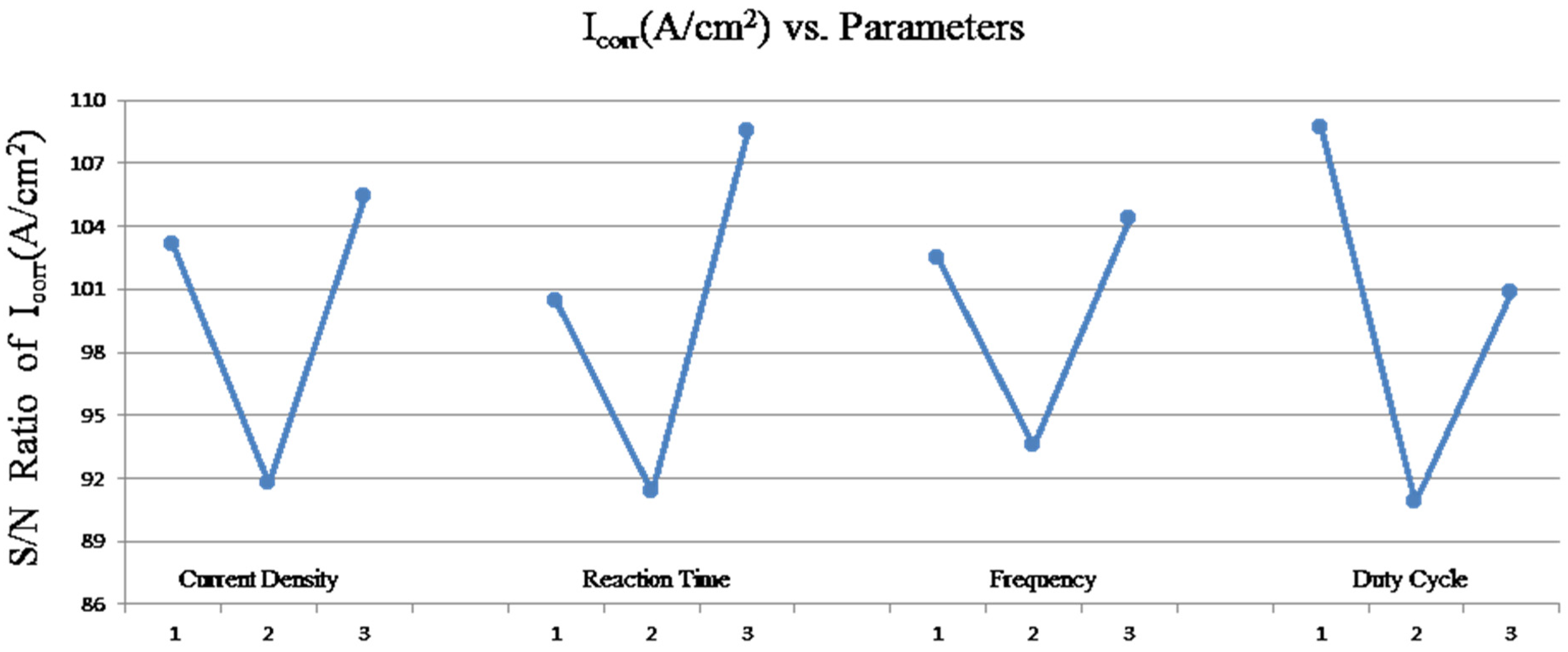
3.1.1. Orthogonal Experiment and Analysis for MAO Process

In this study an attempt has been made to improve the corrosion resistance of the MAO-coated AZ31 Mg alloy by optimizing the MAO processing parameters using the Taguchi method. Figure 1 shows the signal-to-noise (S/N) response graph for the corrosion current density. Despite the objective function (corrosion current density) being a lower-the-better type of control function, the optimal level of the process parameters is the level with the highest S/N ratio. From these graphs it is clear that the optimum values of the factors and their levels are current density of 200 mA/cm2, treatment time of 30 min, pulse frequency of 4000 Hz, and negative duty cycle of 20%.
Taguchi method introduced the following S/N ratio for evaluating the corrosion resistance performance of the system and the quality characteristic deviating from the desired values. It was clearly seen from Figure 1 that duty cycle and treatment time are two of the most important factors due to their higher contributions to reduce the corrosion. To confirm the optimum condition experimentally, additional experiments, such as varying the duty cycle and treatment time, were performed to verify the accuracy of the estimated results by the Taguchi method.

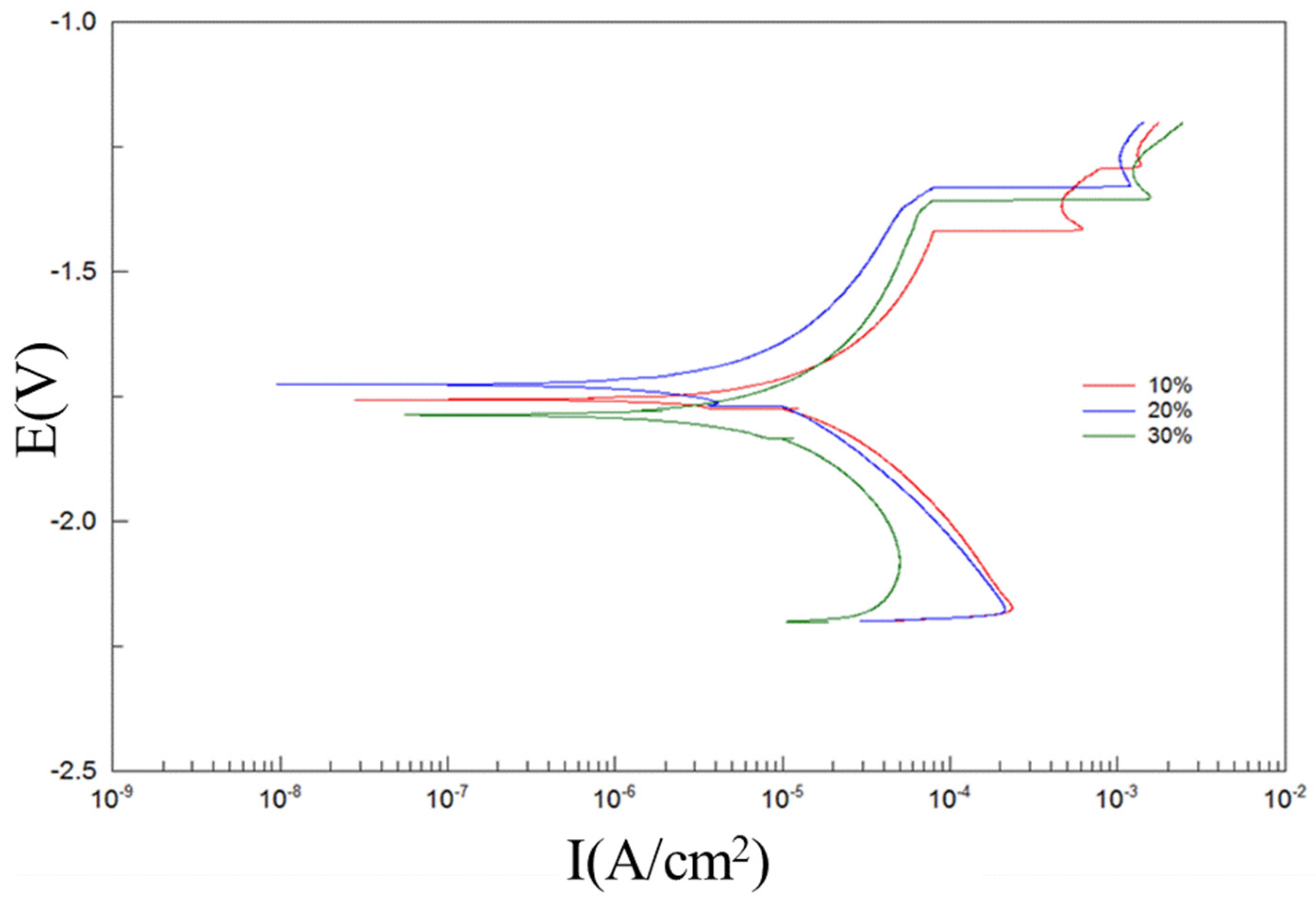
3.1.2. Confirmation Runs for the Negative Duty Cycle

In order to study the influence of the duty cycle on the corrosion behavior and physical properties of the MAO coatings, confirmation tests were conducted for 30 min under a constant current density of 200 mA/cm2, a pulsing frequency of 4000 Hz, and three negative duty cycles of 10%, 20%, and 30%. The relevant results are listed in Table 1. The surface morphology of the MAO-coated AZ31 Mg alloy treated at negative duty cycle of 10%, 20% and 30%, respectively, is displayed in Figure 2a–c. A typical appearance of MAO coatings can be clearly seen from Figure 2. The surfaces of the coatings were dominated by many randomly distributed disc-like structures with open or sealed holes in the center as the result of the formation of discharge channels. SEM images reveal that the MAO-coated AZ31 alloy treated at the negative duty cycle of 20% has relatively less pores and smaller pore size compared to the MAO coatings formed at 10% and 30% negative duty cycles, which is consistent with [33]. The pore diameter showed a tendency to decrease with the increasing negative duty cycle as the negative duty cycle increases from 10% to 20%, while for the negative duty cycle is between 20% and 30%, an increase of pore diameter was evident. The decrease of pore diameter with the increasing negative duty cycle from 10% to 20% can be explained by the randomization of the anodic breakdown sites owing to the occurrence of cathodic breakdown during the cathodic period [34]. On the other hand, more cations will accumulate at the layer/electrolyte interface with increasing negative duty cycle from 20% to 30%, which might result in slightly stronger anodic breakdown and, thus, increasing the pore diameter. The SEM images shown in Figure 2 were image-processed by Image-J software for porosity analysis. The averaged porosities determined from on-surface SEM images are listed in Table 1. The MAO coating prepared with 20% negative duty exhibits the smallest porosity among these three coating as expected. The MAO-coated AZ31 alloy treated at the negative duty cycle of 20% was found to improve the coating quality in terms of surface morphology where the surface became smoother and the micro-pore size was reduced, which might influence the corrosion behavior. Nevertheless, the three duty cycles illustrate much alike surface morphology since such morphologies reflect the very last discharge events.
Cross-sectional SEM images of the coating were used to evaluate the thickness of the MAO layers. Figure 2d–f shows the cross-sections of the AZ31 plate after MAO treated with different duty cycles for 30 min. A very thick MAO layer with thickness about 24.2 μm was formed for the sample coated at 10% negative duty cycle (Figure 2d). The coating thicknesses decreased tremendously with the increase in negative duty cycle from 10% to 20%. A further increase of the negative duty cycle to 30%, the thickness of MAO coating was almost changeless, which are about 7.35 μm. Moreover, the sample prepared at the 30% negative duty cycle shows it has more porosity in the inner layer compared to sample prepared at the 20% negative duty cycle. It has been reported that the anode process promotes the coating growth, whereas the dissolution of some oxide phases on the coating surface takes place during the cathode process [35]. Obviously, the thickness of MAO coating will be governed by the relative rate of coating formation and dissolution. Since the anodic current density remained the same in the present study, it is likely that the increase of cathodic duty cycle promotes the dissolution of oxide layer, thus reducing the thickness of MAO coating. Moreover, the coating formed at the 20% negative duty cycle had a more compact microstructure in the inner layer compared with coatings prepared by the 10% and 30% negative duty cycles.
The results of the EDX analysis carried out on the surface of MAO coatings are given in Table 2. It can be seen from the table that EDX analysis of MAO coatings exhibits the presence of Mg, O, Al, Si, and P. The presence of Mg and Al elements implies that the substrate elements entered into the coating during the MAO process. Elements of Si and P came from the electrolyte. However, it shows the higher concentration of Mg and lower concentrations of Si and P for MAO formed at 20% negative duty cycle when compared with that of MAO formed at the 10% and 30% negative duty cycles. The surface morphology of MAO formed at the 20% negative duty cycle (Figure 2b) exhibited a lower pore density with a smaller pore diameter, which is expected to have a smaller surface area for the adsorption of silicate and phosphorous anions from the electrolyte, which resulted in lower silicon and phosphorous contents over the surface.
XRD spectra of all MAO-coated samples are given in Figure 3. There is no significant difference among these coatings. All the MAO coatings were mainly composed of MgO and MgSiO3. MgO is formed via substrate metal oxidation during MAO treatment, while the MgSiO3 phase is derived from the co-deposition of the alkaline electrolyte components into the coating structure. The Mg3(PO4)2 possibly is existed in the coatings, however, no phosphorous-containing substances were identified by XRD. This might be ascribed to the amount of Mg3(PO4)2 phase is low. The peaks of magnesium in XRD spectra for these three MAO coatings come from the AZ31 Mg alloy substrate, which indicate that the coating is thin.
To examine the adhesion of the MAO layers to the AZ31 Mg alloy substrates, adhesion tape tests according to ASTM D-3359 [32] were carried out. Our results showed that the adhesion of the samples could all be classified as 5B according to the ASTM D3359-17 [32] standard, indicating MAO is a promising surface treatment technology on magnesium alloys which provides good adhesion strength.
Potentiodynamic polarization test in SBF solution was carried out to evaluate the corrosion behavior of the MAO-coated AZ31 alloy (Figure 4). It can be seen that the sample treated at 20% negative duty cycle has more positive corrosion potential compared to other specimens. The corrosion current densities of the MAO coatings formed under negative duty cycle of 10%, 20%, and 30% are 2.23 × 10⁻⁶, 8.05 × 10⁻⁷, and 1.2 × 10⁻⁶ A/cm2, respectively. Table 1 also presents the hydrogen evolution volume after an immersion time of 14 days. Among the three MAO samples treated at different negative duty cycles. It shows from Table 1 that the one treated at negative duty cycle of 20% exhibits the least hydrogen evolution volume (6 mL/14 day), whereas that treated at negative duty cycle of 30% has the most hydrogen evolution volume (16 mL/14 day), followed by the specimen treated at negative duty cycle of 10% (12 mL/14 day). The lower hydrogen evolution rate for MAO coating formed under the 20% negative duty cycle reveals that MAO sample formed under the 20% negative duty cycle can effectively prevent corrosive ions infiltrating into the interior of coating. Based on the above results, it is reasonable to suggest that the 20% negative duty cycle-treated MAO coating exhibits better corrosion resistance than the 10% negative duty cycle-treated specimen, even with a much thinner coating on the surface. This might be ascribed to less micro-pores inside the coating, decreasing the penetration of corrosive medium into the MAO coating and, thus, enhancing its corrosion resistance.

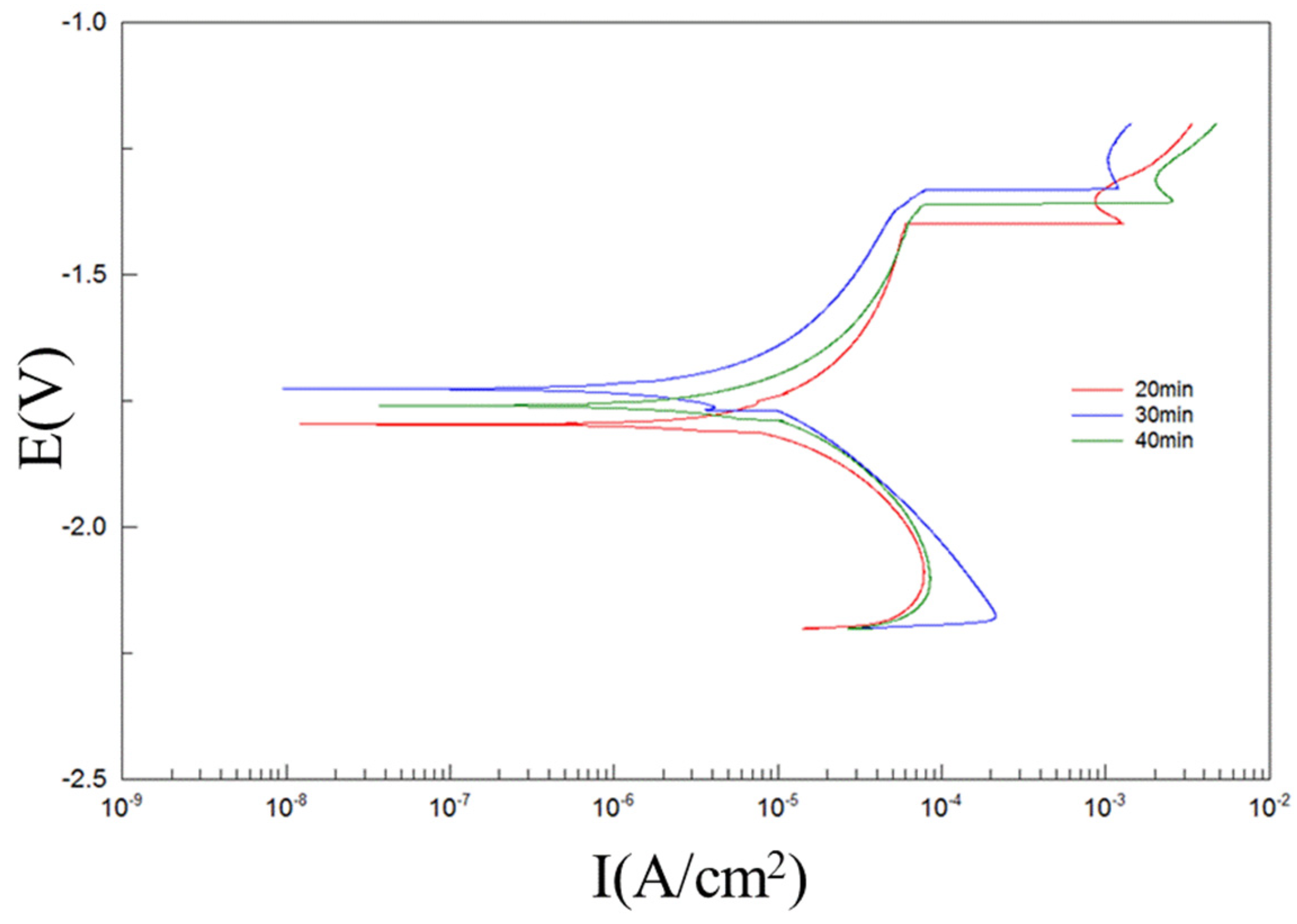
3.1.3. Confirmation Runs for the Treatment Time

To compare the corrosion protection capabilities afforded by the MAO coatings prepared with different treatment times, a confirmation test was conducted at current density of 200 mA/cm2, electrical frequency of 4000 Hz, and a negative duty cycle of 20% for 20, 30, and 40 min, respectively. The surface morphology of the MAO coatings produced with different oxidation times is displayed in Figure 5. Typical MAO porous microstructures were present on all three MAO coatings. The micro-porosity is considered to be “tracks” of the plasma discharge channels, through which the Mg plate and Mg ions from the substrate were likely discharged and reached the coating/electrolyte interface during the plasma-produced melting. The Mg and Mg ions then reacted with oxygen produced by electrolysis, and finally sintered and deposited on the coating surface, so providing to coating growth [36]. Therefore, the highest density of open (un-sealed) channels at the centers of the ‘pancake’ structures were observed on the surface of the 20-min MAO-coated sample (Figure 5a), which is a well-known feature of MAO coatings.
The cross-sectional microstructure of the coatings on AZ31 alloy after MAO processing for different oxidation times is shown in Figure 5d–f. Usually, when the duty ratio decreased, the thickness of the coating also increased due to the increasing treatment time. Figure 5d–f shows the thickness of the MAO coatings formed under treatment time. The coatings were 7.5 μm in 20 min, 8.5 μm in 30 min, and 10.8 μm in 40 min in thickness, respectively. It is demonstrated that the thickness is increasing when the treatment time increasing. Figure 5 also shows that the various samples contain of non-uniform surface oxide coating, the coating thickness is uneven caused by the violent reaction arc on the specimen’s surface. Oxide film grows fast, but is not dense.
XRD patterns of the MAO coatings on AZ31 alloy after different treatment times are shown in Figure 6. All MAO coatings were mainly composed of MgO and MgSiO3. It can be found that the peaks assigned to the substrate Mg decrease dramatically with increasing MAO treatment time, indicating that the coating gets thicker and more compact. In addition, the relative amount of the spinel MgSiO3 phase to the MgO phase increases when the treatment time increases. This may be attributed to the more intense type B discharges prevailing at higher coating thickness. An increase in the intensity and temperature of the micro-arc discharges results in the increase of the reactive activity of the electrolyte component.
The potentiodynamic polarization curves of MAO samples produced with different treatment times in SBF solution are shown in Figure 7. From the curves shown in Figure 7, it can be observed that the sample treated for 30 min has more positive corrosion potential compared to other specimens. The corrosion current density of the sample treated for 30 min was 8.05 × 10⁻⁷ A/cm2, lower than other specimens. This indicates the corrosion behavior of the MAO coating is highly dependent on the treatment time used for the coating formation. The cathodic polarization curve might be thought of as an indication of hydrogen evolution caused by water reduction. The kinetics of the cathodic reaction in the sample treated for 30 min are slower compared with other specimens. This phenomenon indicates that the cathodic reaction was kinetically more difficult in the sample treated for 30 min. The value of Icorr and Ecorr are listed in Table 3, together with thickness, roughness, porosity, and hydrogen evolution volume. From the Table 3, it can be deduced that the noblest corrosion potential and the lowest corrosion current density were attained from the sample treated for 30 min, indicating that this sample corroded slower than other specimens. In conclusion, the corrosion resistance of MAO-coated AZ31 alloy is enhanced with increasing treatment time up to 30 min, while a further increase resulted in the reverse.

3.2. Corrosion Resistance of Electrochemical Analysis

By means of the analyzed level effect, and also analysis of variance in the Taguchi method, we can derive the optimal conditional combination: current density at 200 mA/cm2, electrical frequency at 4000 Hz, duty cycle at 20%, and treatment time of 30 min. After all, the results of the optimal setting showed that the S/N ratios obtained by the optimal results all fall in the 95% dependence interval. This study illustrates that the verification runs prove the reliability in the Taguchi method.
Consequently, in order to further explain the long-term corrosion protection performance of the MAO coatings, it is necessary to obtain a thorough clarification of their corrosion process and the combined electrochemical behaviors. The corrosion properties of the AZ31 substrate and the optimal conditional-coated AZ31 plates were evaluated using a potentiodynamic polarization test and it was conducted after immersion in SBF solution for different time periods of up to seven days. The corrosion current density (Icorr) of the different samples as a function of time is plotted in Figure 8. From this figure, it is apparent that the MAO-coated AZ31 plates had a lesser value of Icorr than the AZ31 substrate in all cases. It can be proposed that the coating formed with the optimal process conditions provides better corrosion protection for the AZ31 Mg alloy.
The corrosion resistance of bare AZ31 substrate and MAO-coated AZ31 obtained under the optimal conditions was further studied using EIS (Figure 9). The Nyquist plot of both samples exhibited a capacitive loop at high and medium frequencies and an inductive loop at low frequencies. It ought to be noted that, in spite of the Nyquist plot form, the sample with the MAO coating exhibits much larger semicircles compared with the uncoated AZ31 alloy sample, suggesting a far better anti-corrosive property compared to that of bare AZ31. It had been expected that the observed micro-pores formed on the MAO coating would have a negative effect on the corrosion performance. However, such an effect wasn’t detected due to the compact inner part of the MAO treatment that provides effective anti-corrosion behavior beneath the outer porous region. Accordingly, the coated substrate exhibited a better corrosion resistance than the uncoated one based on the electrochemical tests.

3.3. Bio-Degradable Implantation Test

In vitro and in vivo studies are necessary to evaluate the biocompatibility and osteoconductivity of these biomaterials before clinical applications. It is worth mentioning that the sample has already passed ISO10993 [37] including cytotoxicity tests, irritation tests, and sensitization tests, which were examined by SGS Taiwan Ltd. (the related proofs are provided in the supplementary materials). To better mimic the performance of MAO-coated Mg alloys in physiological environments, the in vivo implantation test was thus employed in this study. Figure 10 shows the result of the implant surgery after the magnesium bone-screw was implanted in the femora of a mature rabbit. The untreated AZ31 and MAO screws were implanted in vivo as a load-bearing implant to fix a bone fracture and, subsequently, qualitative micro-computed tomography (µCT) analysis and histological analysis were performed respectively at 4, 8, and 12 weeks. µCT scanning was performed to analyze the in vivo degradation of the Mg-based screw, new bone formation around the implant, and the fracture healing process. The representative µCT images of femora with screws at 4, 8 and 12 weeks postoperation were shown in Figure 11. The μCT sequels revealed the preliminary results of the bio-degradation of the untreated AZ31screw (Figure 11A–C) and MAO screw (Figure 11D–F) in the rabbit tissue cells. After 4 weeks implantation, it can be clearly seen from Figure 11A that shadows appeared on the surface of the AZ31 bone-screw, suggesting the corrosion reaction took place between the cell and bone-screw. There was a great decrease in AZ31 screw volume after 12 weeks of implantation (Figure 11C). In addition, bone tissue surrounded screw was observed after 12 weeks. The MAO-coated AZ31, in contrast, had positive influence in bio-degradation test. The bone-screw maintained a bright contrast in the μCT sequels as showed in Figure 11D–F). The MAO screw maintained the original morphology within 12 weeks, whereas AZ31 screw suffered obvious corrosion that several pits present on the surface was observed within 4 weeks. The analysis also revealed a slight decrease in the shrinking dimension of MAO screw compared to AZ31 screw after 12 weeks implantation. According to µCT results, AZ31 and MAO-coated AZ31 exhibited different degradation behaviors. AZ31 alloy degraded quickly, whereas MAO-coated AZ31 showed a slow degradation rate.
It is known that the degradation process was accompanied by hydrogen gas formation [38]. The large amounts of gas accelerate the degradation of the implant, on one hand, and interfere with the bone growth on the other [39]. With the lower degradation rate and correspondingly reduced gas formation, good healing results should be achieved when bones are implanted with MAO screws. This will be shown further by examining the interface between extra bone-screws and bone cells. A series of pathological photographs in Figure 12 provides examples of the extra bone-screw/bone cell interface of AZ31 and MAO screws at each time point. The inner part displayed in Figure 12 showed the extra bone screw and the outer part was the bone cell tissue. As can be seen in Figure 12A–C, the inner part reduced continuously from week 4 to week 12, indicating corrosion progress in the AZ31 screw by week 12. In contrast, the MAO screw was still visible after 12 weeks and the newly formed bones are direct contact to the screw (Figure 12D–F). This can be ascribed to its moderate degradation rate. These observations suggest that the degradation rate of the Mg alloy-based screw can impact its performance, which is consistent with the literature [40]. The AZ31 screw might have a degradation rate which is faster than the healing rate of a bone fracture, and the screw will degrade away before the healing process is over. Our results indicated that the novel Si-P MAO coating had positive effects not only on the bio-degradable results, but also on the bio-compatible trends.

4. Conclusions

In summary, the main findings of the work are:
(1).
This study used the Taguchi method to find out the optimal conditional combination to produce the micro arc oxidation coating on AZ31 Mg alloy with the greatest corrosion resistance. The corrosion resistance of different MAO-coated AZ31 substrates was evaluated by electrochemical measurements carried out in SBF solution. Accordingly, the MAO-coated substrate exhibited a better corrosion resistance than the uncoated one based on the electrochemical tests.
(2).
The optimal conditional combination obtained in this study is: current density of 200 mA/cm2, electrical frequency of 4000 Hz, duty cycle of 20%, and treatment time of 30 min.
(3).
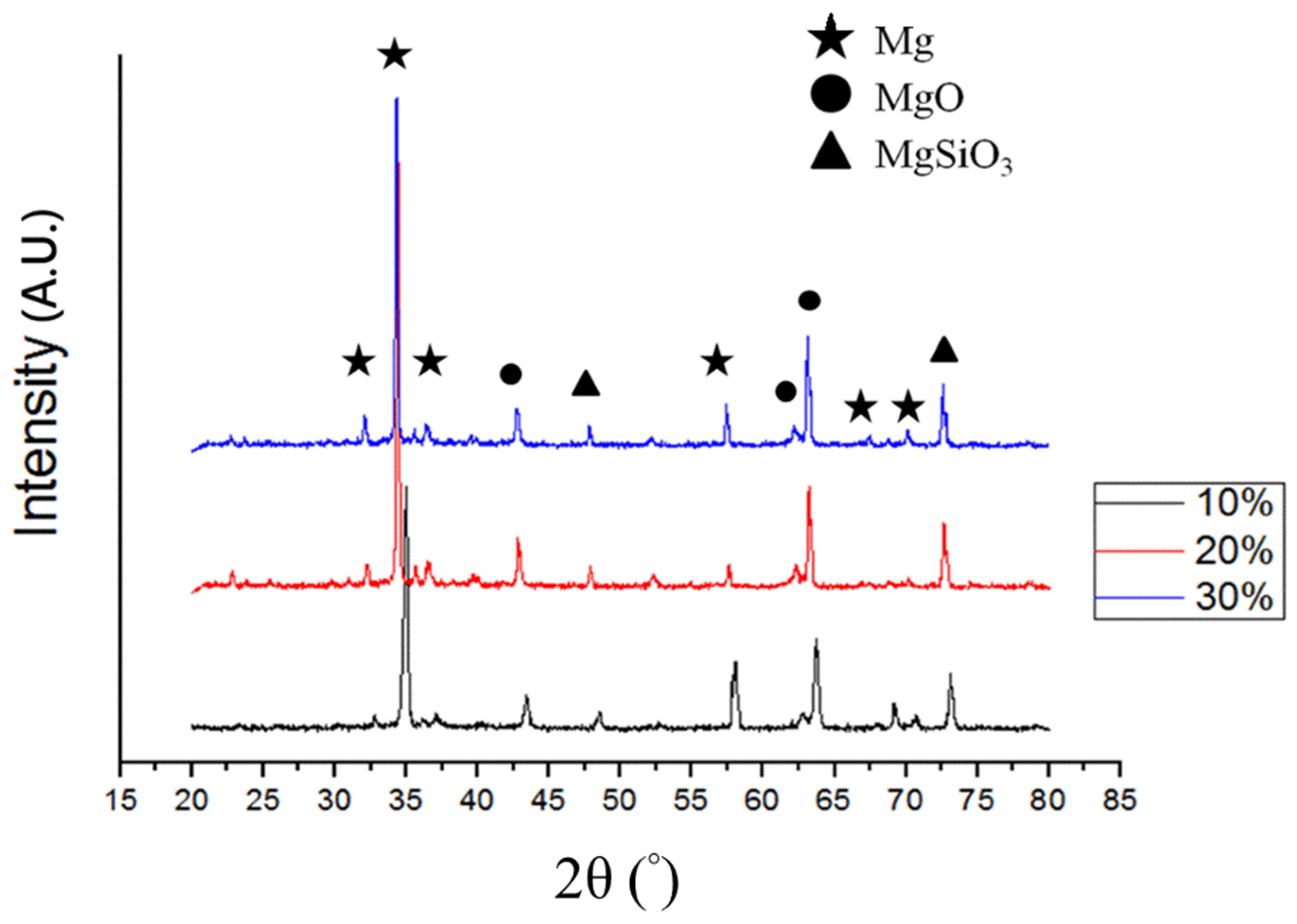
The surface chemical components were analyzed by XRD. The results demonstrated that all the MAO coatings were mainly composed of MgO and MgSiO3. Then, an in vivo testing showed that the MAO-coated AZ31 had good cytocompatibility and anticorrosive properties.
(4).
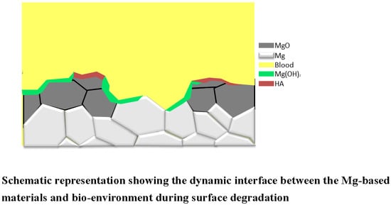
In vivo tests showed that the degradation rate of the Mg alloy-based screw is critical to the success of its application. The well-adhered MAO layer on AZ31 Mg alloy efficiently reduces the degradation rate of the screw. This is beneficial to bone healing.

Supplementary Materials

The following are available online at https://www.mdpi.com/2079-6412/9/6/396/s1.

Author Contributions

Conceptualization, C.-C.T.; Data Curation, B.-C.S., Y.-J.W. and L.-W.W.; Project Administration, M.-W.W. and M.-L.H.; Writing—Original Draft, S.-Y.J.

Funding

This research was funded by Department of Industrial Technology, Ministry of Economic Affair, Taiwan.

Conflicts of Interest

The authors declare no conflict of interest.

References

  1. Ratner, B.D.; Hoffman, A.S.; Schoen, F.J.; Lemons, J.E. Biomaterials Science: An Introduction to Materials in Medicine, 3rd ed.; Elsevier: Amsterdam, The Netherlands, 2012. [Google Scholar]
  2. Jacobsen, N.; Hensten-Pettersen, A. Occupational health problems and adverse patient reactions in orthodontics. Eur. J. Orthod. 1989, 11, 254–264. [Google Scholar] [CrossRef] [PubMed]
  3. Sun, Z.L.; Wataha, J.C.; Hanks, C.T. Effects of metal ions on osteoblast-like cell metabolism and differentiation. J. Biomed. Mater. Res. 1997, 34, 29–37. [Google Scholar] [CrossRef]
  4. Vahey, J.W.; Simonian, P.T. Carcinogenicity and metallic implants. Am. J. Orthop. 1995, 24, 319–324. [Google Scholar] [PubMed]
  5. Zhao, D.; Witte, F.; Lu, F.; Wang, J.; Li, J.; Qin, L. Current status on clinical applications of magnesium-based orthopaedic implants: A review from clinical translational perspective. Biomaterials 2017, 112, 287–302. [Google Scholar] [CrossRef] [PubMed]
  6. Huiskes, R.; Weinans, H.; Van Rietbergen, B. The relationship between stress shielding and bone resorption around total hip stems and the effects of flexible materials. Clin. Orthop. Relat. Res. 1992, 274, 124–134. [Google Scholar] [CrossRef]
  7. Long, M.; Rack, H.J. Titanium alloys in total joint replacement—A materials science perspective. Biomaterials 1998, 19, 1621–1639. [Google Scholar] [CrossRef]
  8. Agins, H.J.; Alcock, N.W.; Bansal, M.; Salvati, E.A.; Wilson, P.D.; Pellicci, P.M.; Bullough, P.G. Metallic wear in failed titanium-alloy total hip replacements. A histological and quantitative analysis. J. Bone Joint Surg. 1988, 70, 347–356. [Google Scholar] [CrossRef]
  9. Dearnley, P.A.; Dahm, K.L.; Çimenoǧlu, H. The corrosion—Wear behaviour of thermally oxidised CP-Ti and Ti–6Al–4V. Wear 2004, 256, 469–479. [Google Scholar] [CrossRef]
  10. Wu, G.; Ibrahim, J.M.; Chu, P.K. Surface design of biodegradable magnesium alloys—A review. Surf. Coat. Technol. 2013, 233, 2–12. [Google Scholar] [CrossRef]
  11. Minkowitz, R.B.; Bhadsavle, S.; Walsh, M.; Egol, K.A. Removal of painful orthopaedic implants after fracture union. J. Bone Joint Surg. Am. 2007, 89, 1906–1912. [Google Scholar]
  12. Zreiqat, H.; Howlett, C.R.; Zannettino, A.; Evans, P.; Schulze-Tanzil, G.; Knabe, C.; Shakibaei, M. Mechanisms of magnesium-stimulated adhesion of osteoblastic cells to commonly used orthopaedic implants. J. Biomed. Mater. Res. 2002, 62, 175–184. [Google Scholar] [CrossRef] [PubMed]
  13. Kirkland, N.T.; Birbilis, N. Magnesium Biomaterials: Design, Testing, and Best Practice; Springer: Cham, Switzerland, 2014. [Google Scholar]
  14. Song, G.; Song, S.Z. A Possible biodegradable magnesium implant material. Adv. Eng. Mater. 2007, 9, 298–302. [Google Scholar] [CrossRef]
  15. Córdoba, L.C.; Montemor, M.F.; Coradin, T. Silane/TiO2 coating to control the corrosion rate of magnesium alloys in simulated body fluid. Corros. Sci. 2016, 104, 152–161. [Google Scholar] [CrossRef]
  16. Hiromoto, S. Self-healing property of hydroxyapatite and octacalcium phosphate coatings on pure magnesium and magnesium alloy. Corros. Sci. 2015, 100, 284–294. [Google Scholar] [CrossRef]
  17. Lei, T.; Ouyang, C.; Tang, W.; Li, L.F.; Zhou, L.S. Enhanced corrosion protection of MgO coatings on magnesium alloy deposited by an anodic electrodeposition process. Corros. Sci. 2010, 52, 3504–3508. [Google Scholar] [CrossRef]
  18. Cai, Q.; Wang, L.; Wei, B.; Liu, Q. Electrochemical performance of microarc oxidation films formed on AZ91D magnesium alloy in silicate and phosphate electrolytes. Surf. Coat. Technol. 2006, 200, 3727–3733. [Google Scholar] [CrossRef]
  19. Arrabal, R.; Matykina, E.; Viejo, F.; Skeldon, P.; Thompson, G.E. Corrosion resistance of WE43 and AZ91D magnesium alloys with phosphate PEO coatings. Corros. Sci. 2008, 50, 1744–1752. [Google Scholar] [CrossRef]
  20. Witte, F.; Kaese, V.; Haferkamp, H.; Switzer, E.; Meyer-Lindenberg, A.; Wirth, C.J.; Windhagen, H. In vivo corrosion of four magnesium alloys and the associated bone response. Biomaterials 2005, 26, 3557–3563. [Google Scholar] [CrossRef]
  21. Narayanan, T.S.; Park, I.S.; Lee, M.H. Strategies to improve the corrosion resistance of microarc oxidation (MAO) coated magnesium alloys for degradable implants: Prospects and challenges. Prog. Mater. Sci. 2014, 60, 1–71. [Google Scholar] [CrossRef]
  22. Mori, Y.; Koshi, A.; Liao, J.; Asoh, H.; Ono, S. Characteristics and corrosion resistance of plasma electrolytic oxidation coatings on AZ31B Mg alloy formed in phosphate—Silicate mixture electrolytes. Corros. Sci. 2014, 88, 254–262. [Google Scholar] [CrossRef]
  23. Yue, Y.A.N.G.; Hua, W.U. Effect of current density on corrosion resistance of micro-arc oxide coatings on magnesium alloy. T. Nonferr. Metal. Soc. China 2010, 20, s688–s692. [Google Scholar]
  24. Liu, J.; Zhang, W.; Zhang, H.; Hu, X.; Zhang, J. Effect of microarc oxidation time on electrochemical behaviors of coated bio-compatible magnesium alloy. Strategies to improve the corrosion resistance of microarc oxidation (MAO) coated magnesium alloys for degradable implants: Prospects and challenges. Mater. Today Proc. 2014, 1, 70–81. [Google Scholar] [CrossRef]
  25. Gu, Y.; Chen, C.F.; Bandopadhyay, S.; Ning, C.; Zhang, Y.; Guo, Y. Corrosion mechanism and model of pulsed DC microarc oxidation treated AZ31 alloy in simulated body fluid. Appl. Surf. Sci. 2012, 258, 6116–6126. [Google Scholar] [CrossRef]
  26. Hussein, R.O.; Zhang, P.; Nie, X.; Xia, Y.; Northwood, D.O. The effect of current mode and discharge type on the corrosion resistance of plasma electrolytic oxidation PEO) coated magnesium alloy AJ62. Surf. Coat. Technol. 2011, 206, 1990–1997. [Google Scholar] [CrossRef]
  27. Hussein, R.O.; Nie, X.; Northwood, D.O. Influence of process parameters on electrolytic plasma discharging behaviour and aluminum oxide coating microstructure. Surf. Coat. Technol. 2010, 205, 1659–1667. [Google Scholar] [CrossRef]
  28. Ben-Arfa, B.A.; Salvado, I.M.M.; Frade, J.R.; Pullar, R.C. Fast route for synthesis of stoichiometric hydroxyapatite by employing the Taguchi method. Mater. Des. 2016, 109, 547–555. [Google Scholar] [CrossRef]
  29. Song, G. Control of biodegradation of biocompatable magnesium alloys. Corros. Sci. 2007, 49, 1696–1701. [Google Scholar] [CrossRef]
  30. Atrens, A.; Liu, M.; Abidin, N.I.Z. Corrosion mechanism applicable to biodegradable magnesium implants. Mater. Sci. Eng. B 2011, 176, 1609–1636. [Google Scholar] [CrossRef]
  31. Neil, W.C.; Forsyth, M.; Howlett, P.C.; Hutchinson, C.R.; Hinton, B.R.W. Corrosion of heat treated magnesium alloy ZE41. Corros. Sci. 2011, 53, 3299–3308. [Google Scholar] [CrossRef]
  32. ASTM D-3359. Standard Test Methods for Rating Adhesion by Tape Test; ASTM International: West Conshohocken, PA, USA, 2017. [Google Scholar]
  33. Lee, S.J.; Do Toan, L.H.; Lee, J.L.; Chen, C.Y.; Peng, H.C. Effects of pulsed unipolar and bipolar current regimes on the characteristics of micro-arc oxidation coating on LZ91 magnesium-lithium alloy. Int. J. Electrochem. Sci. 2018, 13, 2705–2717. [Google Scholar] [CrossRef]
  34. Sah, S.P.; Tsuji, E.; Aoki, Y.; Habazaki, H. Cathodic pulse breakdown of anodic films on aluminium in alkaline silicate electrolyte—Understanding the role of cathodic half-cycle in AC plasma electrolytic oxidation. Corros. Sci. 2012, 55, 90–96. [Google Scholar] [CrossRef]
  35. Yerokhin, A.L.; Nie, X.; Leyland, A.; Matthews, A. Characterisation of oxide films produced by plasma electrolytic oxidation of a Ti–6Al–4V alloy. Surf. Coat. Technol. 2000, 130, 195–206. [Google Scholar] [CrossRef]
  36. Hussein, R.O.; Nie, X.; Northwood, D.O. An investigation of ceramic coating growth mechanisms in plasma electrolytic oxidation (PEO) processing. Electrochim. Acta 2013, 112, 111–119. [Google Scholar] [CrossRef]
  37. ISO 10993-1. Standard Test Methods for Biological Evaluation of Medical Devices-Part 1: Evaluation and Testing within a Risk Management Process; ISO: Geneva, Switzerland, 2018. [Google Scholar]
  38. Wilke, B.M.; Zhang, L.; Li, W.; Ning, C.; Chen, C.F.; Gu, Y. Corrosion performance of MAO coatings on AZ31 Mg alloy in simulated body fluid vs. Earle’s balance salt solution. Appl. Surf. Sci. 2016, 363, 328–337. [Google Scholar] [CrossRef]
  39. Waizy, H.; Diekmann, J.; Weizbauer, A.; Reifenrath, J.; Bartsch, I.; Neubert, V.; Schavan, R.; Windhagen, H. In vivo study of a biodegradable orthopedic screw (MgYREZralloy) in a rabbit model for up to 12 months. J. Biomater. Appl. 2014, 28, 667–675. [Google Scholar] [CrossRef] [PubMed]
  40. Zhang, N.; Zhao, D.; Liu, N.; Wu, Y.; Yang, J.; Wang, Y.; Xie, H.; Ji, Y.; Zhou, C.; Zhuang, J.; et al. Assessment of the degradation rates and effectiveness of different coated Mg-Zn-Ca alloy scaffolds for in vivo repair of critical-size bone defects. J. Mater. Sci. Mater. Med. 2018, 29, 138. [Google Scholar] [CrossRef]
Figure 1. Effect of factors on corrosion current density (Icorr) of the coatings.
Coatings 09 00396 g001
Figure 2. SEM-images of the surface (ac) and cross-section (df) of the MAO coatings produced at negative duty cycle of 10% (a,d), 20% (b,e), and 30% (c,f), respectively, for 30 min.
Coatings 09 00396 g002
Figure 3. XRD patterns of oxide coatings formed at negative duty cycle of 10%, 20%, and 30%, respectively, for 30 min.
Coatings 09 00396 g003
Figure 4. Potentiodynamic polarization curve of the MAO coating on the substrate surface formed at negative duty cycle of 10%, 20%, and 30%, respectively, for 30 min in the SBF.
Coatings 09 00396 g004
Figure 5. SEM-images of the surface (ac) and cross-section (df) of the MAO coatings produced at negative duty cycle of 20% for treatment times of 20 min (a,d), 30 min (b,e), and 40 min (c,f).
Coatings 09 00396 g005
Figure 6. XRD patterns of oxide coatings formed at negative duty cycle of 20% for treatment times of 20, 30, and 40 min.
Coatings 09 00396 g006
Figure 7. Potentiodynamic polarization curve of the MAO coating on the substrate surface formed at negative duty cycle of 20% for treatment times of 20, 30, and 40 min in the SBF.
Coatings 09 00396 g007
Figure 8. Corrosion current density of the bare and MAO-coated AZ31 Mg alloy immersed in SBF solution for different times.
Coatings 09 00396 g008
Figure 9. Impedance spectra of bare and MAO-coated AZ31 Mg alloy in the SBF after immersion of 7 days.
Coatings 09 00396 g009
Figure 10. The surgery image of the implantation of the magnesium bone-screw in the femora of a mature rabbit.
Coatings 09 00396 g010
Figure 11. The µCT reconstructed images showing the degradation processes of AZ31 bone-screw (AC) and MAO coating (DF) after implantation of 4, 8, and 12 weeks.
Coatings 09 00396 g011
Figure 12. Pathological photographs of the screw/bone interfaces after AZ31 substrate (AC) and the MAO coating (DF) implanted in a mature rabbit for 4, 8, and 12 weeks.
Coatings 09 00396 g012
Table 1. Negative duty cycle effect on thickness, surface roughness, porosity, and corrosion current density of MAO-coated AZ31 Mg alloy.
Duty Cycle (%)Thickness (µm)Surface Roughness (µm)Porosity (%)Current Density (Icorr A/cm2)Hydrogen Volumes (mL/14 days)
1024.20.454.652.23 × 10−612
207.650.492.528.05 × 10−76
307.351.103.571.2 × 10−616
Table 2. EDX analysis of the MAO coatings prepared at different negative duty cycles.
Duty Cycle (%)Elements (wt %)
OMgAlSiPCa
1046.4240.091.1110.361.620.39
2038.2952.311.636.451.160.16
3047.8839.781.119.721.390.12
Table 3. Treatment time effect on thickness, surface roughness, porosity, and corrosion current density of MAO-coated AZ31 Mg alloy.
Treatment Time (min)Thickness (µm)Surface Roughness (µm)Porosity (%)Corrosion Current Density (Icorr A/cm2)Hydrogen Volumes (mL/14 days)
207.501.213.883.06 × 10−610
307.650.492.528.05 × 10−76
4010.80.683.651.13 × 10−67

