LDH Post-Treatment of Flash PEO Coatings


1
Departamento de Ciencia de Materiales, Facultad de Ciencias Químicas, Universidad Complutense, 28040 Madrid, Spain
2
School of Materials, University of Manchester, Oxford Road, Manchester M13 9PL, UK
*
Author to whom correspondence should be addressed.
Coatings 2019, 9(6), 354; https://doi.org/10.3390/coatings9060354
Submission received: 25 April 2019
/
Revised: 23 May 2019
/
Accepted: 28 May 2019
/
Published: 30 May 2019
(This article belongs to the Special Issue Plasma Electrolytic Oxidation (PEO) Coatings)
Abstract
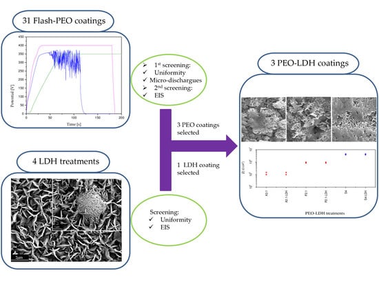
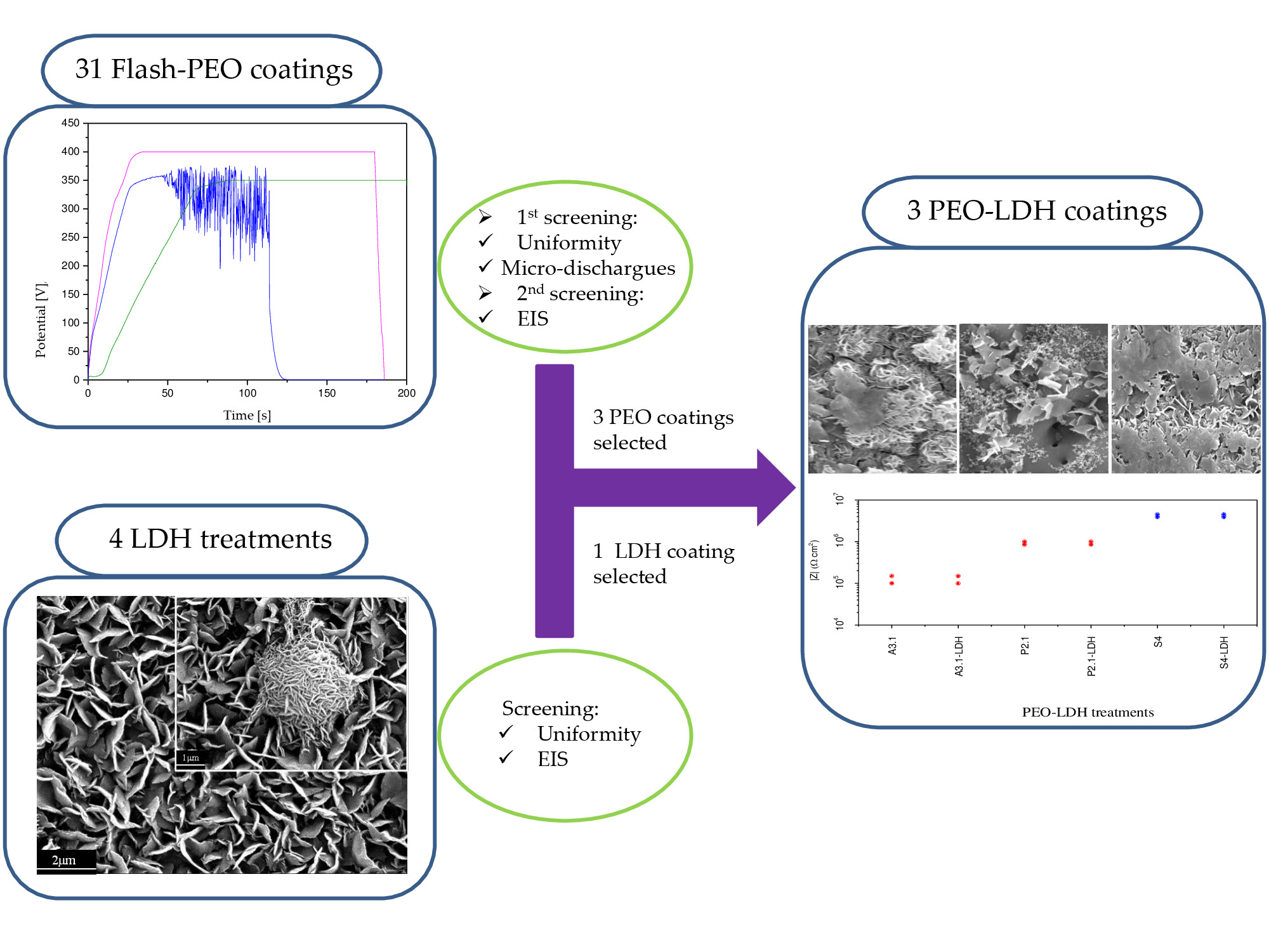
:This work investigates environmentally friendly alternatives to toxic and carcinogenic Cr (VI)-based surface treatments for aluminium alloys. It is focused on multifunctional thin or flash plasma electrolytic oxidation (PEO)-layered double hydroxides (LDH) coatings. Three PEO coatings developed under a current-controlled mode based on aluminate, silicate and phosphate were selected from 31 processes (with different combinations of electrolytes, electrical conditions and time) according to corrosive behavior and energy consumption. In situ Zn-Al LDH was optimized in terms of chemical composition and exposure time on the bulk material, then applied to the selected PEO coatings. The structure, morphology and composition of PEO coatings with and without Zn-Al-LDH were characterized using XRD, SEM and EDS. Thicker and more porous PEO coatings revealed higher amounts of LDH flakes on their surfaces. The corrosive behavior of the coatings was studied by electrochemical impedance spectroscopy (EIS). The corrosion resistance was enhanced considerably after the PEO coatings formation in comparison with bulk material. Corrosion resistance was not affected after the LDH treatment, which can be considered as a first step in achieving active protection systems by posterior incorporation of green corrosion inhibitors.
1. Introduction
Plasma electrolytic oxidation (PEO) is a plasma-assisted electrochemical surface treatment characterized by the utilization of high voltages (100–600 V) in alkaline electrolytes to produce ceramic-like coatings on light alloys such as aluminium [1], magnesium [2] and titanium [3]. This technology may become a potential alternative to conventional toxic and highly carcinogenic chromic acid anodizing (CAA) for niche applications [4,5,6].
The PEO process can be conducted under direct current (DC) [7], alternate current (AC) [8], unipolar [9] or bipolar pulsed regimes [10] involving polarization of the alloy to voltages above the dielectric breakdown of the oxide. This results in the formation of multiple short-lived microdischarges on the metallic surface that trigger the formation of highly stable ceramic phases [1,11,12]. The resulting PEO coatings present high hardness, thermal stability and adherence to the substrate, which lead to enhanced corrosion and tribological properties. Moreover, the coatings’ microstructures and compositions can be tailored as required by controlling electrical parameters during the coating synthesis by electrolyte selection and by the application of pre- and post-treatments [13,14].
However, the costs associated with PEO technology are relatively high, which is mainly due to high energy consumption. General current densities and voltages for the PEO process are in the range of 1.5–15 A·dm−2 and 400–500 V for Mg [15], 6–20 A·dm−2 and 200–500 V for Ti [16] and 10–60 A·dm−2 and 200–400 V for Al [17]. Typical PEO treatment times are within a 15–60 min range.
In the particular case of Al and its alloys, the efficiency of conversion of the anodic charge into the final coating material may be as low as 20%, due to gas generation and dissolution processes [18,19,20]. Therefore, energy consumption of the process must be reduced in order to make this technology commercially viable for high-volume applications [10,14,20,21]. Strategies to achieve this goal involve waveform design and cell geometry [22], electrolyte design [23,24,25,26,27]) and a pre-anodizing approach [18]. An additional strategy consists of “flash” PEO—processes of a short duration (1–3 min) that produce thin coatings (1–5 μm) suitable and sufficient for many corrosion resistance-demanding applications.
PEO coating properties can be improved even further by incorporating active functionalities. This can be achieved by introducing smart agents into the coatings matrix, which are released in situ, triggered by an external stimulus [23,24,25]. Coatings based on LDH have increasing potential not only for developing smart functionalities on ceramic materials, but in many other fields, such as biomaterials, due to their low toxicity [23].
LDHs can be expressed by the general formula [M2+1−XM3+X(OH)2]X+(Am−)X/m·nH2O], where M2+ and M3+ represent divalent metallic cations (e.g., Mg2+, Zn2+, etc.) and trivalent metallic cations (e.g., Al3+, Co3+, etc.), respectively, and Am− is the interlayer anion (e.g., NO3−, Cl−, etc.) [26]. It consists of uniform flakes that grow roughly vertically on the substrate and act as intelligent nanocontainers that release, in a controlled way, the previously loaded corrosion inhibitors. The active corrosion protection mechanism is based on anion-exchange reactions induced by particular triggers, such as increases in the aggressiveness of the surrounding environment or initiation of the corrosion process [26,27].
The most common approach to synthesizing LDH is the in situ growth method, due to its low cost and ease of synthesizing at laboratory and industrial scales [28]. In this method, the source of Al3+ ions required to grow the LDH structure is the metallic substrate, and it results in coatings with better adherence compared to LDH coatings synthesized by other routes such as hydrothermal treatment [29,30,31], which is characterized by the use of autoclave to get high temperatures, or the urea hydrolysis method, which is used to form well-crystallized large LDH [32,33,34].
The knowledge of multifunctional surfaces with active protection based on ceramic-like coatings (PEO) is at an embryonic stage [35]. Y. Zhang [36] investigated the growth behavior of LDH layers on PEO-coated aluminum alloy. It was found that LDH grains are preferentially formed on the micro-pores of PEO coatings to provide effective film repairs. The most dominant factor which determines the PEO/LDH system behavior is the interaction between the electrolyte anions and Al(OH)2+ cations from PEO coating surface. This phenomenon has a major impact on the kinetic mechanism of the formation of LDH coating [37,38]. F. Chen [39] demonstrated that flakes were preferentially formed in the PEO pores at the initial stage of LDHs growth; it was also found that long-term corrosion resistance was significantly enhanced due to the limited penetration of corrosive ions [38]. The corrosive degradation of the substrate coated with PEO is accelerated by chloride ions in the environment. From a corrosion-relevance perspective, the entrapment of chloride anions via the ion-exchange mechanism is the most critical factor for designing efficient corrosion protection strategies. In fact, partial entrapment is possible when the PEO layer is sealed with LDH [40].
Although the concept of LDH-based post-treatment for sealing the PEO layers has been recently proven, many variables remain unexplored. In particular, this work is focused on the formation of in situ Zn-Al LDH on low energy consumption PEO coatings. For that, three PEO coatings were selected from 31 processes (with different combination of electrolytes, electrical conditions and time) based on corrosive behavior and energy consumption. The selected materials were thoroughly characterized and evaluated in terms of corrosion resistance.
2. Materials and Methods
2.1. Material
The composition of the 1050-H18 aluminum alloy (Famimetal S.L., Madrid, Spain) in wt.% is: 0.07 Zn, 0.05 Mn, 0.25 Si, 0.05 Cu, 0.40 Fe, 0.05 Mg, 0.05 Ti, 0.03 V and Al balance.
2.2. Specimens Preparation
The samples were cut from sheets into specimens of 30 × 20 × 1.5 mm3 dimensions, ground to P1200 silicon carbide abrasive paper, rinsed in distilled water and methanol and dried in warm air. Prior to the PEO processing, specimens were etched in 15 wt.% sodium hydroxide solution for 20 s, rinsed in deionized water and dried in warm air. The working area was then limited to ∼3 cm2 using a commercial resin (Lacquer 45, MacDermid plc., Birmingham, UK).
2.3. Surface Treatment Based on PEO
PEO coatings were obtained using different electrolytes and conditions in order to grow thin PEO coatings with low energy consumption (Table 1) under vigorous agitation. The experimental system was carried out with a DC voltage/current-controlled power supply (SM400-AR-8 Systems electronic) equipped with a thermostatic jacket (25 ± 1 °C) under continuous electrolyte agitation. An AISI 316 steel plate of 7.5 × 15 cm2 size was used as a counter electrode. After the PEO process, all samples were rinsed in distilled water and isopropanol and dried in warm air.
2.4. Synthesis of Zn-Al-LDH Growth
Zn-Al LDH-nitrate (LDH-NO3) was synthesized on AA1050-H18 aluminium alloy. The specimens were immersed in the solution for different times under continuous stirring in order to form LDH (Table 2), then rinsed in deionized water and dried in air at room temperature.
2.5. Characterization
Planar and cross-sectional views of the specimens were examined using a JEOL JSM 6335F (Tokyo, Japan) field emission scanning electron microscope (FESEM) working at 20 kV and equipped with an energy dispersive (EDS) spectrometer (OXFORD X-MAX, Oxford, UK). Coating cross-sections were ground through successive grades of SiC paper and polished to a 1 μm diamond finish.
Phase composition was examined by X-ray diffraction (XRD), with a Philips X’Pert MRD (Amsterdam, The Netherlands, Cu Kα = 1.54056 Å). The XRD patterns were taken using grazing incidence with a step size of (0.01°–1°) and a dwell time of 6 s per step at room temperature.
The specific energy consumption was calculated by integration of the voltage-time and current-time transients acquired by the power supply (SM 400AR-8 Systems electronic) during the PEO treatment (Equation (1)). With the obtained results, the energy consumption was calculated in terms of kW·h·m−2 according to Equation (1), and the specific energy consumption in kW·h·m−2·µm−1 was obtained dividing Ptot by the coating thickness.
2.6. Electrochemical Behavior
Electrochemical impedance spectroscopy (EIS) was used to evaluate the corrosion resistance of the different coatings in an aqueous saline solution (NaCl 3.5 wt.%) at 25 °C. For that, a GillAC (ACM Instruments, Cumbria, UK) computer-controlled potentiostat and a three-electrode cell were used. The specimen was connected as a working electrode with an exposed area of 1 cm2. A graphite electrode and a silver–silver chloride (Ag/AgCl) electrode used as the counter and the reference electrode, respectively. The solution inside the reference electrode was KCl 3 M, which provided a potential of 0.210 V with respect to the standard hydrogen electrode. The tests applying a sinusoidal perturbation of 10 mV RMS amplitude in the frequency range of 30 kHz–0.01 Hz were carried out after 1 h of immersion. All measurements were duplicated to ensure reproducibility.
3. Results and Discussion
3.1. PEO Coating Screening
The first screening process to select one PEO coating per electrolyte type was conducted in accordance with three factors: (i) presence of microdischarges during coating formation, (ii) visually uniform coating morphology and (iii) coating thickness ≥1 μm.
Among the different alternatives based on different electrolyte compositions, PEO coatings developed in phosphate and silicate electrolytes showed more promising results (with lower breakdown voltage values, beneficial for low energy consumption) (Table 3) and therefore additional process conditions were also tried (V (V): 350; j (A·cm−2): 0.05; t (s): 200) (Table 1).
Finally, only the A3.1, A3.2, P2.1, S1.3, S2.6 and S4 PEO coatings (Table 1) fulfilled the previous requirements.
The last step of the screening process consisted of a corrosion evaluation based on the value of the modulus of the impedance obtained by electrochemical impedance spectroscopy (EIS). Figure 1 shows the |Z| × 10−2 Hz values of the studied materials, providing an estimation of the corrosion resistance, where higher values of |Z| indicate a lower corrosion rate [41].
With the aim of studying the influence of electrolytes on LDH growth, three PEO coatings were selected (one per electrolyte composition: aluminate A3.1, phosphate 2.1 and silicate S4). The specific energy consumption of selected coatings was calculated (Table 3) by integration of the voltage-time and current-time transients (Figure 2) recorded during the PEO process to verify that the developed coatings were energy efficient. The obtained values reveal the effect of electrolyte composition on energy consumption, coating growth rate and breakdown voltage values (Table 3).
As can be seen in Figure 2, the current drop was observed only in aluminate and silicate electrolyte cases (Figure 2a,c) when 400 and 350 V limitations (Table 1) were achieved after 40 and 75 s of treatment, respectively, and the power supply switched to a constant voltage-control mode. Typically, when the current density was below 20 mA·cm−2, the microdischarges extinguished; the anodizing, however, was carried on till set time in order to repair microdefects in the oxide material [42].
The fact that the limiting voltage was reached (hence the current drop) could be explained by high coating density and, consequently, higher resistance of the oxide to charge and mass transfer that were achieved at early stages [18]. High value of energy consumption in the case of aluminate is mainly due to the fact that aluminate species in the electrolyte gave rise to the formation of coating composed of nearly pure alumina, which has very low electron conductivity (i.e., the current flows mainly by ion and not by electron transfer) [12]. Further, the high breakdown voltage (320 V) in the aluminate electrolyte compelled the use of a higher voltage limit (400 V) in order to ensure a long enough period of sparking in order to achieve a uniform coating of a significant thickness; this yielded a higher specific energy consumption value.
As a result, the dielectric breakdown voltage was high, the limiting set voltage was achieved quickly and, as a consequence of the current drop, the sparking period was short, hence the low coating growth rate [22,43]. Similarly, high value of energy consumption in the case of phosphate electrolyte, where sparking was observed until the end of the treatment and coating growth rate was relatively high, was due to the absence of current drop, because the limiting 350 V were never reached. In this case, higher resistance of the oxide to charge and mass transfer were achieved at 60 s, giving rise to intense microdischarges and voltage variations, and therefore the treatment was stopped at 115 s in order to maintain coating uniformity.
The lowest energy consumption of 2.2 kW·h·m−2·µm−1 was achieved in case of silicate electrolyte. This was mainly the result of its high electrical conductivity and, therefore, low Ubd. The onset of microdischarges early in the treatment and the relatively long sparking period before current decay resulted in the intermediate coating growth rate value (Table 3).
The specific energy consumption values obtained under DC conditions in the present work are similar to those reported in studies carried out under AC conditions. For example, E. Matykina et al. developed a PEO coating on pure aluminium using silicate electrolyte, and obtained a growth rate of 1.3 µm·min−1 and energy consumption values of 4.77 KW·h·m−2·µm−1 [18]. Y.L. Cheng et al. reported a growth rate of 11.3 µm·min−1 and energy consumption values of 5 KW·h·m−2·µm−1 for Al-Cu alloy in concentrated aluminate electrolyte [44]. It is well known that DC conditions promote low growth rates in comparison with AC conditions [18,22]; however, in this study the values obtained were considerably lower compared with the available data for different PEO treatments on commercial Al alloys, which can be as high as 26.7 kW·h·m−2·µm−1 [18]. The present findings demonstrate that in order to reduce specific energy consumption under DC conditions it is necessary to (i) limit the final forming voltage that ensures a current drop, and (ii) use electrolytes with conductivity, which ensures low microdischarges onset voltages and extended sparking periods, as in the case of the S4 electrolyte.
3.2. PEO Coatings Characterization
Figure 3 shows the planar view and cross-section scanning electron micrographs of AA1050 coated by selected PEO coatings. All selected treatments show a thin oxide layer of 1–2.5 µm (Table 3). This is particularly evident in aluminate electrolyte-based PEO coating (A3.1), where the Al-Fe intermetallic compounds from the substrate are still visible in the coating (Figure 3a, inset) due to its low thickness. This coating is also more heterogeneous (Figure 3b) than the rest, which is attributable to its high breakdown voltage values (Figure 2) [37,45,46] and, as mentioned before, its low coating growth rate. Phosphate electrolyte-based PEO coating (P2.1) showed a homogeneous (Figure 3c) surface appearance (Figure 3c), and the highest thickness value (Figure 3d). This was mainly due to the presence of polyphosphate species that participated in PEO coating formation and favored its high coating growth rate [47]. Silicate electrolyte-based PEO coating (S4) (Figure 3e), with the lowest breakdown voltage, showed a homogeneous surface morphology with very sparse submicrometric pores. The latter may be attributable to the formation of a thin superficial glassy layer of SiO2, which can be surmised from the EDS analysis where the presence of 1.5 at.% Si in the coatings and a greater content of oxygen than in the other two coatings was confirmed.
3.3. LDH Screening
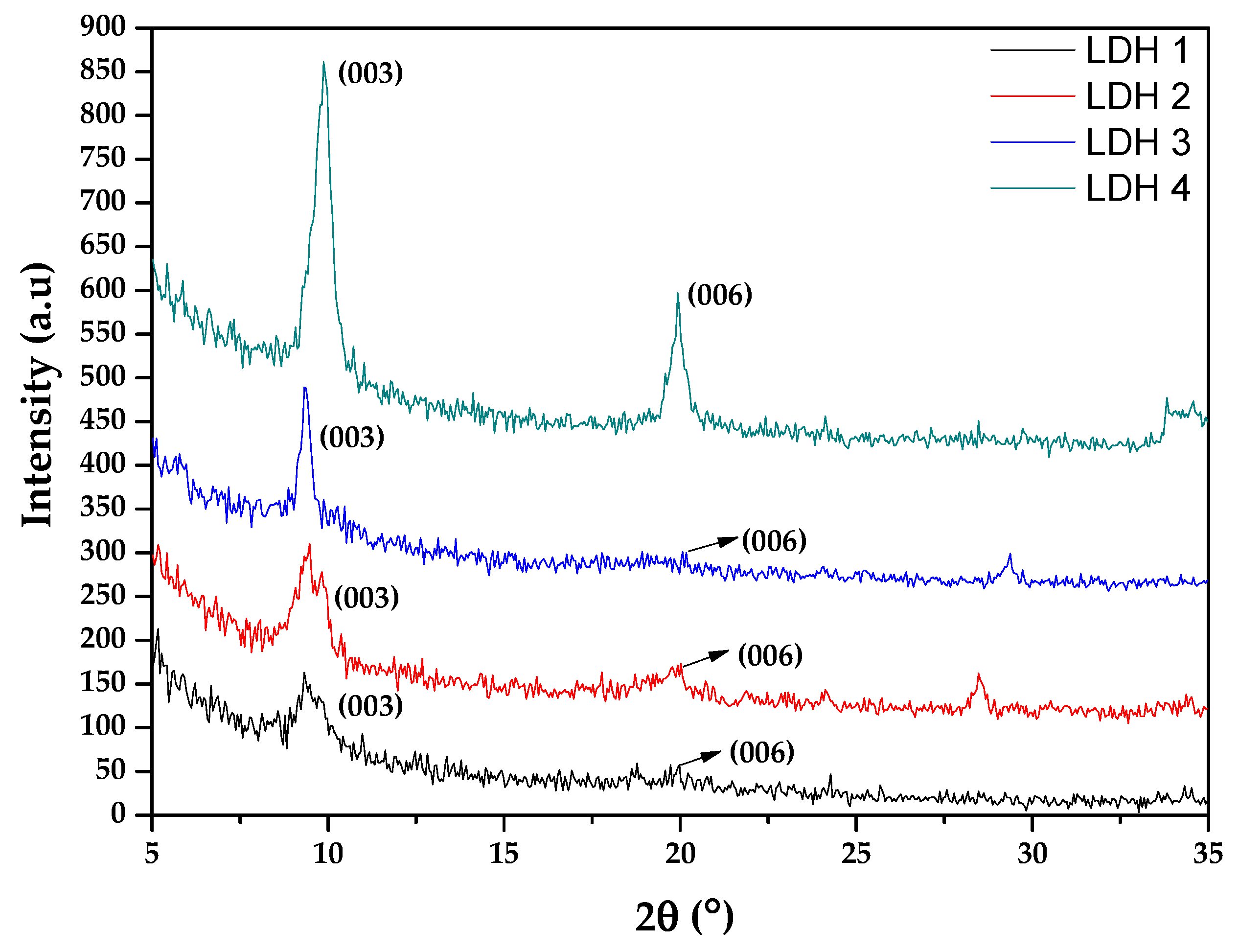
The effect of reactant composition and treatment time during the growth of LDH coatings were investigated. Figure 4 depicts the XRD patterns of the different LDH treatments (Table 2) grown on the bulk material. The presence of peaks at 9.6° and 19.9° corresponding to the characteristic (003) and (006) reflections of LDHs intercalated with NO3− [32,48,49] indicates the formation of LDH under the different conditions.
It was revealed that treatments containing NaNO3 in the solution led to more defined and intense peaks, probably due to the presence of sodium ions in the LDH gallery [50]. On the contrary, the presence of NH4NO3 drove the formation of broadened peaks [51]. In fact, just in the case of LDH grown in NH4NO3, a small peak was revealed at 9.9° that could be associated with an LDH phase intercalated with carbonate, due to the formation of LDH layers under atmospheric conditions [52].
LDHs formed under long treatment times (LDH 2 and 4) showed very strong peaks in comparison with LDHs formed under short treatment times (LDH 1 and 3), mainly because an increment in the LDH degree of crystallinity took place [51].
The correlation between XRD patterns of studied LDH coatings and planar view scanning electron micrographs were investigated. Figure 5 shows secondary electron images of the LDH treatments (Table 2) grown on the pure aluminium.
The typical flake-like LDH structure could be clearly observed for LDH carried out in NH4NO3 at short treatment times, whereas LDH developed in NaNO3 formed this structure at long exposure times. According to Figure 5a, the LDH structure carried out in the presence of NH4NO3 is in good agreement with the XRD patterns that showed broadened peaks and, consequently, a highly open LDH structure. Additionally, Figure 5b clearly shows (also consistent with the XRD pattern) a non-defined LDH structure, which is usually attributed to the incorporation of carbonate ions into the LDH gallery [48]. However, LDH developed in NaNO3 showed typical curved plate-like LDH microcrystals at long exposure times, and a non-defined structure at short exposure times (Figure 5c,d). This was mainly due to an increment in the degree of LDH crystallinity that was observed in XRD patterns (Figure 4).
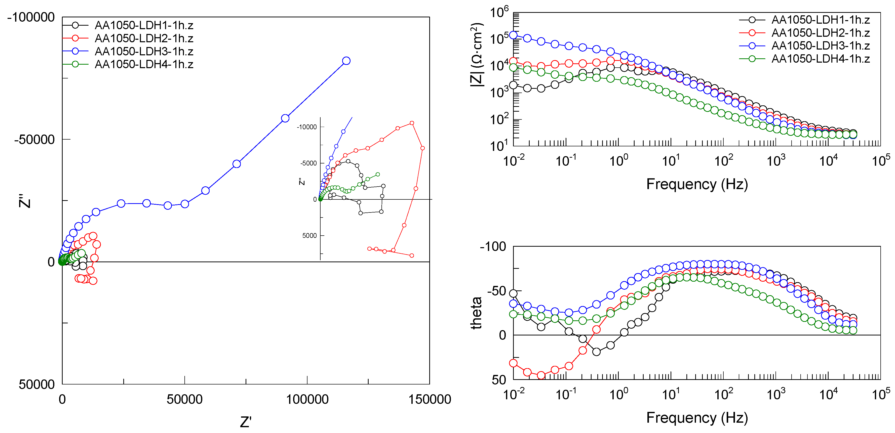
In order to evaluate the correlation between the corrosion protection and the structure of studied LDHs, a screening process based on corrosion performance (EIS) was carried out. Figure 6 depicts the Bode and Nyquist plots for AA1050 alloy with studied LDH coatings.
From the point of view of coating structure, the presence of spheroidal particles in flake-like LDH 1 and LDH 4 (Figure 5) [14] was associated with the presence of secondary phases [35,36,37] that favored aluminium cation dissolution due to their highly cathodic behavior [48]. In addition, the porous structure of these spheroidal particles also favored Cl− anion penetration into the LDH gallery, and for this reason these coatings showed the lowest corrosion protection among the studied LDH coatings (Figure 6) [53,54,55]. From the point of view of corrosion protection of non-defined LDH coatings, it should be noted that LDH 2 showed similar corrosion behavior in comparison with LDH 4, which can be attributed to its intermediate non-porous LDH structure (Figure 5). On the contrary, LDH 3 provided a beneficial effect to corrosion protection in comparison with all the studied LDH coatings. This may be due to the presence of sodium ions in the LDH gallery, which facilitate the formation of non-porous corrosion-protective LDH coating (Figure 6). For this reason, LDH 3 was the selected treatment to use for the selected PEO coatings and study their anti-corrosion properties (Figure 6).
3.4. PEO-LDH Coating Characterization
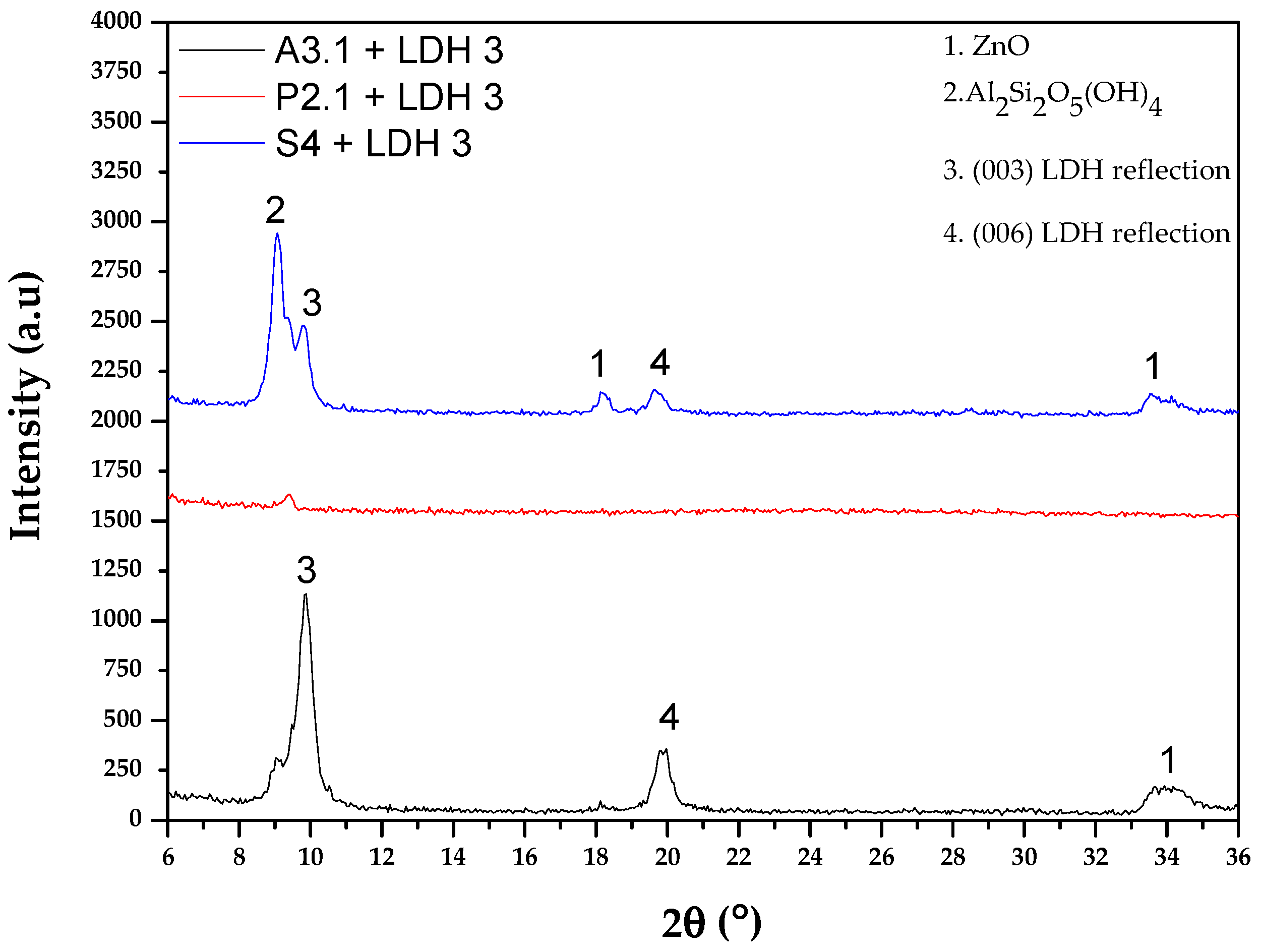
Figure 7 depicts the XRD patterns of selected PEO coatings (A3.1, P2.1 and S4) with LDH 3 and discloses the effects of the PEO coating compositions on LDH growth.
PEO coatings based on aluminate and silicate electrolytes showed the typical peaks at 9.6° and 19.9°, which corresponded to the characteristic (003) and (006) reflections of LDH intercalated with NO3− [32,48,49]. Additionally, the presence of ZnO and Al2Si2O5(OH)4 characteristic peaks in the S4-LDH XRD pattern came from LDH chemical composition (Table 2) and silicate electrolytes, respectively (Table 1).
In the particular case of PEO coating developed in phosphate electrolyte, there were no peaks detected in that range. This could be attributed to the formation of non-crystalline phases, or to only a small amount that could not be detected at the selected scan rate (Figure 7).
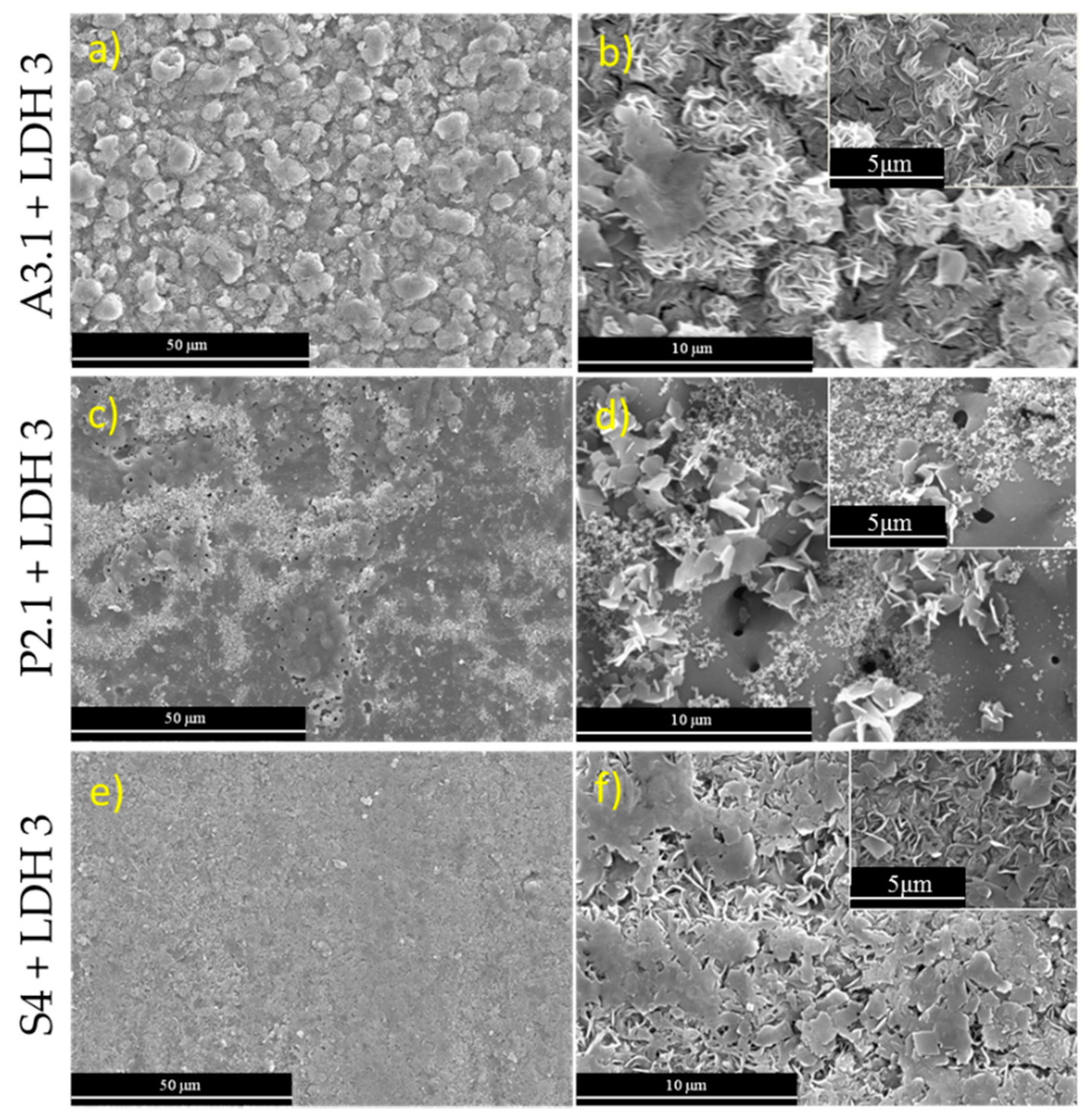
Figure 8 highlights a detailed morphology of the selected PEO-LDH coatings, which reveals the importance of PEO coating composition. The characteristic flake-like LDH structure can be clearly observed for the A3.1-LDH coating, in which LDH flakes are covering the whole PEO coating (Figure 8a,b). This is also observable in the S4-LDH coating, but in this case is more heterogenous (Figure 8e,f). These results are in accordance with XRD patterns that showed the presence of these characteristic reflections (Figure 7). However, for the P2.1-LDH coating there is a drastic decrease of the density of LDH-like flakes (Figure 8c,d), which is in accordance with the XRD patterns (Figure 7).
This fact is in strong agreement with a high dependence on the availability of Al(OH)2+ cations necessary to form Zn-Al-LDH. According to previous studies [40,56], Zn-Al LDH synthesis can be explained via the following chemical reactions:
As mentioned before, the in situ growth method was used in the present work and, consequently, Al(OH)2+ cations were an essential requirement to form the LDH layers. Due to the porous structure of PEO coatings and their compositions, two sources can provide Al(OH)2+ cations: (i) the aluminium metal matrix (due to the electrochemical interactions with LDH solutions), and PEO coating thickness [57].
Firstly, in consideration of the PEO coating cross-section (Figure 3) and planar view micrographs after LDH treatment (Figure 8), it can be concluded that the amount of LDH flakes on the selected PEO coatings was highest for A3.1, and lowest for the P2.1 and S4 coatings. This could firstly be explained by thickness, and secondly by the chemical composition of the PEO coating surfaces. Due to the low thickness of the A3.1 PEO coating (~1 µm) (Figure 3a,b), the migration capacity of Al(OH)2+ cations from the aluminium metal matrix towards the coating surface was ensured. However, the P2.1 (Figure 3c,d) and S4 (Figure 3e,f) PEO coatings showed higher thickness values (~1.5–2 µm), and, consequently, the migration capacity of Al(OH)2+ was reduced. With respect to the chemical composition of PEO coating surfaces, the aluminium content decreased in the order A3.1 > P2.1 > S4 (Figure 3, EDS analysis table) due to the presence of aluminate species in the A3.1 electrolyte. Further, greater charge passed during the P2.1 treatment, and intense sparking from the onset of the microdischarges until the end of the treatment (Figure 2b) resulted in greater thickness and density of the P2.1 coatings. Consequently, a highly heterogeneous LDH layer was achieved in comparison with the S4 PEO coating. This justifies the absence of peaks in XRD patterns of the P2.1-LDH (Figure 7).
3.5. Corrosion Resistance of PEO + LDH Coatings
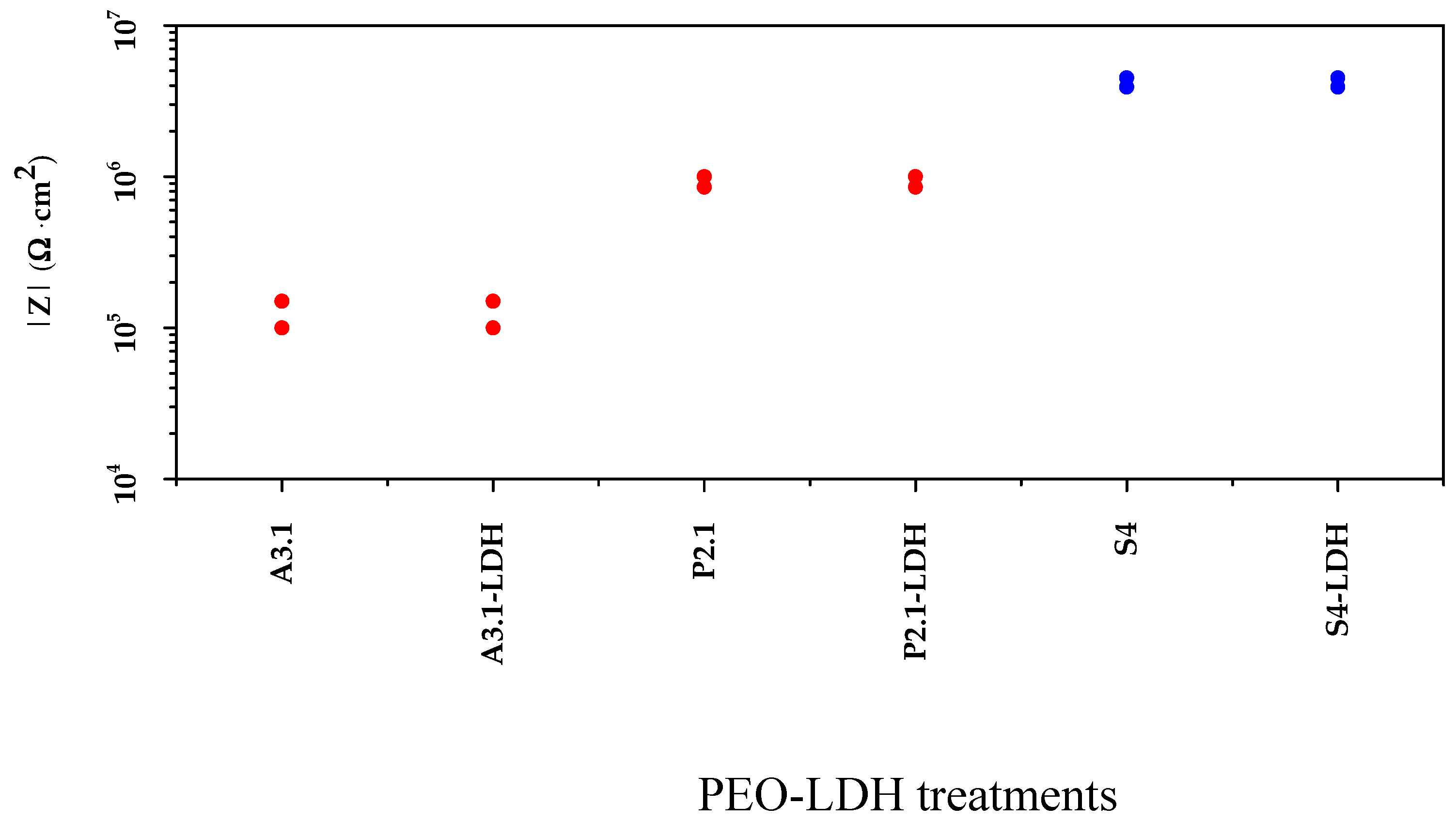
In order to evaluate the effect of LDH formation on selected PEO coatings, corrosion resistance was measured by electrochemical impedance spectroscopy (EIS) for 1 h of immersion in 3.5 wt.% NaCl solution at room temperature (Figure 9).
As can be seen in Figure 9, PEO coatings with and without LDH treatment showed high similitude of the impedance modulus.
It is important to note that, in this work, the corrosion resistance of different PEO coatings was strongly connected with PEO coating porosity, because the lack of pores restricts the Cl− penetration and prevents its detrimental effects [58]. For this reason, A3.1 showed the lowest corrosion resistance due to the combination of pores and heterogeneities in comparison with the P2.1 and S4 coatings. The highest corrosion protection exhibited by the S4 PEO coating (~5 × 10⁶ Ω·cm2) may be attributed to its sparse surface porosity due to the formation of a glassy silica-rich layer.
In this work, the results showed similar behavior of PEO-LDH compared with PEO coatings without any clear improvement after the post-treatment. This could be attributed to several factors, for instance: (i) LDH flake resistance was negligible compared with that of the PEO coating, and (ii) PEO coating lost some of its barrier properties during the formation of LDH, somewhat retracting from the possible small beneficial effect of the LDH layer.
It should be noted that no studies of LDH formation on flash PEO coatings (at <5 min anodizing time) have been reported so far. However, based on this work and few works carried out with non-flash PEO of aluminium, some conclusions can be drawn regarding the effects of LDH post-treatments. For instance, when an LDH layer is not loaded with inhibitors, the corrosion resistance remains unchanged or degrades slightly, as has been shown in [37]. On the other hand, when LDH is intercalated with an inhibitor (e.g., vanadate ions), an improvement in corrosion resistance is observed with immersion time due to an active protection effect [37,38].
The present findings highlight that the development of LDH-container layers did not deteriorate the corrosion resistance of flash PEO coatings, which has a potential for added active protection functionality. Therefore, the first stage of active protection system building can be considered successful. The second stage would consist of loading the LDH scaffold with corrosion inhibitors that would ensure enhanced corrosion protection.
In conclusion, these results are highly relevant for understanding the relation between coherent and uniform LDH layer formations on flash PEO coatings, which is the first step in achieving active protection systems through the incorporation of green corrosion inhibitors into the LDH layer.
4. Conclusions
The following can be summarized from this preliminary study of LDH growth on flash PEO coatings:
- Flash PEO coatings with ~1–2 µm thickness and ~2–5 KW·h·m−2·µm−1 energy consumption were genereated on a commercially pure aluminum alloy. Low energy consumption was ensured through relatively high electrolyte conductivity and a transition of the anodizing regime from constant current to constant voltage control.
- The first stage of the active protection system was successfully completed on flash PEO coatings via the development of an LDH layer. LDH coating is continuous and well defined when the PEO layer is thin (~1 μm), and the LDH formation is further facilitated when additional Al(OH)2+ cations are lixiviated from the coating.
- Corrosion resistance of inhibitor-free flash PEO/LDH coatings is mainly determined by the low porosity of the PEO layer. Formation of the LDH layer does not compromise the corrosion resistance of flash PEO coatings. Loading of the LDH scaffold with corrosion inhibitors is necessary in order to achieve an enhanced corrosion protection.
Author Contributions
Formal Analysis, R.d.O., M.M., B.M., R.A. and E.M.; Funding Acquisition, M.M.; Investigation, R.d.O. and M.M.; Methodology, R.d.O. and M.M.; Resources, M.M. and E.M.; Supervision, R.A. and E.M.; Writing—Original Draft, R.d.O., M.M. and B.M.; Writing—Review & Editing, R.A. and E.M.; Conceptualization, R.d.O., M.M., B.M., R.A. and E.M.; Software, R.d.O., M.M., B.M., R.A. and E.M.; Validation, R.d.O, M.M., B.M., R.A. and E.M.; Data Curation, R.d.O., M.M. and B.M.; Visualization, R.d.O., M.M., B.M., R.A. and E.M.; Project Administration R.A. and E.M.
Funding
This work was partially supported by (MAT2015-73355-JIN), ADITIMAT-CM (S2018/NMT-4411) and RTI2018-096391-B-C33 MCIU/AEI/FEDER, UE. MM is grateful to the Ramon y Cajal Programme (MICINN, Spain, RYC-2017-21843).
Conflicts of Interest
The authors declare no conflict of interest.
References
- Matykina, E.; Arrabal, R.; Skeldon, P.; Thompson, G. Investigation of the growth processes of coatings formed by AC plasma electrolytic oxidation of aluminium. Electrochim. Acta 2009, 54, 6767–6778. [Google Scholar] [CrossRef]
- Arrabal, R.; Matykina, E.; Hashimoto, T.; Skeldon, P.; Thompson, G. Characterization of AC PEO coatings on magnesium alloys. Surf. Coat. Technol. 2009, 203, 2207–2220. [Google Scholar] [CrossRef]
- Matykina, E.; Skeldon, P.; Thompson, G.E. Fundamental and practical evaluations of PEO coatings of titanium. Int. Heat Surf. Eng. 2009, 3, 45–51. [Google Scholar] [CrossRef]
- Abrahami, S.T.; De Kok, J.M.M.; Mol, J.M.C.; Terryn, H. Towards Cr(VI)-free anodization of aluminum alloys for aerospace adhesive bonding applications: A review. Front. Chem. Sci. Eng. 2017, 11, 465–482. [Google Scholar] [CrossRef]
- Kulinich, S.; Akhtar, A.S. On conversion coating treatments to replace chromating for Al alloys: Recent developments and possible future directions. Russ. J. Non-Ferrous Met. 2012, 53, 176–203. [Google Scholar] [CrossRef]
- Gharbi, O.; Thomas, S.; Smith, C.; Birbilis, N. Chromate replacement: What does the future hold? npj Mater. Degrad. 2018, 2, 12. [Google Scholar] [CrossRef]
- Khan, R.; Yerokhin, A.; Li, X.; Dong, H.; Matthews, A. Surface characterisation of DC plasma electrolytic oxidation treated 6082 aluminium alloy: Effect of current density and electrolyte concentration. Surf. Coat. Technol. 2010, 205, 1679–1688. [Google Scholar] [CrossRef]
- Guan, Y.; Xia, Y.; Li, G. Growth mechanism and corrosion behavior of ceramic coatings on aluminum produced by autocontrol AC pulse PEO. Surf. Coat. Technol. 2008, 202, 4602–4612. [Google Scholar] [CrossRef]
- Han, I.; Choi, J.H.; Zhao, B.H.; Baik, H.K.; Lee, I.-S. Changes in anodized titanium surface morphology by virtue of different unipolar DC pulse waveform. Surf. Coat. Technol. 2007, 201, 5533–5536. [Google Scholar] [CrossRef]
- Yerokhin, A.; Shatrov, A.; Samsonov, V.; Shashkov, P.; Pilkington, A.; Leyland, A.; Matthews, A. Oxide ceramic coatings on aluminium alloys produced by a pulsed bipolar plasma electrolytic oxidation process. Surf. Coat. Technol. 2005, 199, 150–157. [Google Scholar] [CrossRef]
- Dunleavy, C.; Curran, J.; Clyne, T. Time dependent statistics of plasma discharge parameters during bulk AC plasma electrolytic oxidation of aluminium. Appl. Surf. Sci. 2013, 268, 397–409. [Google Scholar] [CrossRef]
- Matykina, E.; Arrabal, R.; Skeldon, P.; Thompson, G.; Belenguer, P. AC PEO of aluminium with porous alumina precursor films. Surf. Coat. Technol. 2010, 205, 1668–1678. [Google Scholar] [CrossRef]
- Curran, J.; Clyne, T. Thermo-physical properties of plasma electrolytic oxide coatings on aluminium. Surf. Coat. Technol. 2005, 199, 168–176. [Google Scholar] [CrossRef]
- Barik, R.; Wharton, J.; Wood, R.; Stokes, K.; Jones, R.; Wharton, J. Corrosion, erosion and erosion–corrosion performance of plasma electrolytic oxidation (PEO) deposited Al2O3 coatings. Surf. Coat. Technol. 2005, 199, 158–167. [Google Scholar] [CrossRef]
- Srinivasan, P.B.; Liang, J.; Blawert, C.; Stormer, M.; Dietzel, W. Effect of current density on the microstructure and corrosion behaviour of plasma electrolytic oxidation treated AM50 magnesium alloy. Appl. Surf. Sci. 2009, 255, 4212–4218. [Google Scholar] [CrossRef] [Green Version]
- Aliasghari, S. Plasma Electrolytic Oxidation of Titanium. Ph.D. Thesis, The University of Manchester, Manchester, UK, September 2014. [Google Scholar]
- Mohedano, M.; Lu, X.; Matykina, E.; Blawert, C.; Arrabal, R.; Zheludkevich, M.L. Plasma electrolytic oxidation (PEO) of metals and alloys. In Encyclopedia of Interfacial Chemistry, 1st ed.; Wandelt, K., Ed.; Elsevier: Amsterdam, The Netherlands, 2018; pp. 423–438. [Google Scholar]
- Matykina, E.; Arrabal, R.; Pardo, A.; Mohedano, M.; Mingo, B.; Rodríguez, I.; González, J. Energy-efficient PEO process of aluminium alloys. Mater. Lett. 2014, 127, 13–16. [Google Scholar] [CrossRef] [Green Version]
- Sinko, J. Challenges of chromate inhibitor pigments replacement in organic coatings. Prog. Org. Coat. 2001, 42, 267–282. [Google Scholar] [CrossRef]
- Snizhko, L.; Yerokhin, A.; Gurevina, N.; Patalakha, V.; Matthews, A.; Snizhko, L. Excessive oxygen evolution during plasma electrolytic oxidation of aluminium. Thin Solid Films 2007, 516, 460–464. [Google Scholar] [CrossRef]
- Snizhko, L.; Yerokhin, A.; Pilkington, A.; Gurevina, N.; Misnyankin, D.; Leyland, A.; Matthews, A.; Snizhko, L. Anodic processes in plasma electrolytic oxidation of aluminium in alkaline solutions. Electrochim. Acta 2004, 49, 2085–2095. [Google Scholar] [CrossRef]
- Matykina, E.; Arrabal, R.; Mohedano, M.; Mingo, B.; Gonzalez, J.; Pardo, A.; Merino, M. Recent advances in energy efficient PEO processing of aluminium alloys. Trans. Nonferrous Met. Soc. China 2017, 27, 1439–1454. [Google Scholar] [CrossRef]
- Yasakau, K.; Tedim, J.; Zheludkevich, M.; Ferreira, M.; Yasakau, K.; Zheludkevich, M. Smart self-healing coatings for corrosion protection of aluminium alloys. In Handbook of Smart Coatings for Materials Protection, 1st ed.; Woodhead Publishing: Cambridge, UK, 2014; pp. 224–274. [Google Scholar]
- Mardel, J.; Garcia, S.; Corrigan, P.; Markley, T.; Hughes, A.; Muster, T.; Lau, D.; Harvey, T.; Glenn, A.; White, P.; et al. The characterisation and performance of Ce(dbp)3-inhibited epoxy coatings. Prog. Org. Coat. 2011, 70, 91–101. [Google Scholar] [CrossRef]
- Osborne, J.H.; Blohowiak, K.Y.; Taylor, S.; Hunter, C.; Bierwagon, G.; Carlson, B.; Bernard, D.; Donley, M.S. Testing and evaluation of nonchromated coating systems for aerospace applications. Prog. Org. Coat. 2001, 41, 217–225. [Google Scholar] [CrossRef]
- Guo, L.; Wu, W.; Zhou, Y.; Zhang, F.; Zeng, R.; Zeng, J. Layered double hydroxide coatings on magnesium alloys: A review. J. Mater. Sci. Technol. 2018, 34, 1455–1466. [Google Scholar] [CrossRef]
- Williams, G.; Geary, S.; McMurray, H.; McMurray, H. Smart release corrosion inhibitor pigments based on organic ion-exchange resins. Corros. Sci. 2012, 57, 139–147. [Google Scholar] [CrossRef]
- Cavani, F.; Trifirò, F.; Vaccari, A. Hydrotalcite-type anionic clays: Preparation, properties and applications. Catal. Today 1991, 11, 173–301. [Google Scholar] [CrossRef]
- Guo, X.; Xu, S.; Zhao, L.; Lu, W.; Zhang, F.; Evans, D.G.; Duan, X. One-step hydrothermal crystallization of a layered double hydroxide/alumina bilayer film on aluminum and its corrosion resistance properties. Langmuir 2009, 25, 9894–9897. [Google Scholar] [CrossRef] [PubMed]
- Zhang, F.; Zhang, C.-L.; Song, L.; Zeng, R.-C.; Liu, Z.-G.; Cui, H.-Z. Corrosion of in-situ grown MgAl-LDH coating on aluminum alloy. Trans. Nonferrous Met. Soc. China 2015, 25, 3498–3504. [Google Scholar] [CrossRef]
- Xu, Z.P.; Lu, G.Q. Hydrothermal synthesis of layered double hydroxides (LDHs) from mixed MgO and Al2O3: LDH formation mechanism. Chem. Mater. 2005, 17, 1055–1062. [Google Scholar] [CrossRef]
- Hao, L.; Yan, T.; Zhang, Y.; Zhao, X.; Lei, X.; Xu, S.; Zhang, F. Fabrication and anticorrosion properties of composite films of silica/layered double hydroxide. Surf. Coat. Technol. 2017, 326, 200–206. [Google Scholar] [CrossRef]
- Zhang, Y.; Li, Y.; Ren, Y.; Wang, H.; Chen, F. Double-doped LDH films on aluminum alloys for active protection. Mater. Lett. 2017, 192, 33–35. [Google Scholar] [CrossRef]
- Staal, L.B.; Pushparaj, S.S.C.; Forano, C.; Prevot, V.; Ravnsbæk, D.B.; Bjerring, M.; Nielsen, U.G. Competitive reactions during synthesis of zinc aluminum layered double hydroxides by thermal hydrolysis of urea. J. Mater. Chem. A 2017, 5, 21795–21806. [Google Scholar] [CrossRef]
- Dou, B.; Wang, Y.; Zhang, T.; Liu, B.; Shao, Y.; Meng, G.; Wang, F. Growth behaviors of layered double hydroxide on microarc oxidation film and anti-corrosion performances of the composite film. J. Electrochem. Soc. 2016, 163, C917–C927. [Google Scholar] [CrossRef]
- Zhang, Y. Investigating the growth behavior of LDH layers on MAO-coated aluminum alloy: Influence of microstructure and surface element. Int. J. Electrochem. Sci. 2018, 13, 610–620. [Google Scholar] [CrossRef]
- Mohedano, M.; Serdechnova, M.; Starykevich, M.; Karpushenkov, S.; Bouali, A.; Ferreira, M.; Zheludkevich, M. Active protective PEO coatings on AA2024: Role of voltage on in-situ LDH growth. Mater. Des. 2017, 120, 36–46. [Google Scholar] [CrossRef]
- Serdechnova, M.; Mohedano, M.; Kuznetsov, B.; Mendis, C.L.; Starykevich, M.; Karpushenkov, S.; Tedim, J.; Ferreira, M.G.S.; Blawert, C.; Zheludkevich, M.L. PEO coatings with active protection based on in-situ formed LDH-nanocontainers. J. Electrochem. Soc. 2017, 164, C36–C45. [Google Scholar] [CrossRef]
- Chen, F.; Yu, P.; Zhang, Y. Healing effects of LDHs nanoplatelets on MAO ceramic layer of aluminum alloy. J. Alloy. Compd. 2017, 711, 342–348. [Google Scholar] [CrossRef]
- Tedim, J.; Kuznetsova, A.; Salak, A.; Montemor, F.; Snihirova, D.; Pilz, M.; Zheludkevich, M.; Ferreira, M.; Salak, A.; Zheludkevich, M. Zn–Al layered double hydroxides as chloride nanotraps in active protective coatings. Corros. Sci. 2012, 55, 1–4. [Google Scholar] [CrossRef]
- Liu, Y.; Yin, X.; Zhang, J.; Yu, S.; Han, Z.; Ren, L. A electro-deposition process for fabrication of biomimetic super-hydrophobic surface and its corrosion resistance on magnesium alloy. Electrochim. Acta 2014, 125, 395–403. [Google Scholar] [CrossRef]
- Tsunekawa, S.; Aoki, Y.; Habazaki, H. Two-step plasma electrolytic oxidation of Ti–15V–3Al–3Cr–3Sn for wear-resistant and adhesive coating. Surf. Coat. Technol. 2011, 205, 4732–4740. [Google Scholar] [CrossRef]
- Baron-Wiechec, A.; Burke, M.; Hashimoto, T.; Liu, H.; Skeldon, P.; Thompson, G.; Habazaki, H.; Ganem, J.-J.; Vickridge, I. Tracer study of pore initiation in anodic alumina formed in phosphoric acid. Electrochim. Acta 2013, 113, 302–312. [Google Scholar] [CrossRef]
- Cheng, Y.; Cao, J.; Mao, M.; Xie, H.; Skeldon, P. Key factors determining the development of two morphologies of plasma electrolytic coatings on an Al–Cu–Li alloy in aluminate electrolytes. Surf. Coat. Technol. 2016, 291, 239–249. [Google Scholar] [CrossRef]
- Sykes, J.; Thompson, G.E.; Mayo, D.; Skeldon, P. Anodic film formation on high strength aluminium alloy FVS0812. J. Mater. Sci. 1997, 32, 4909–4916. [Google Scholar] [CrossRef]
- Fratila-Apachitei, L.; Tichelaar, F.; Thompson, G.; Terryn, H.; Skeldon, P.; Duszczyk, J.; Katgerman, L. A transmission electron microscopy study of hard anodic oxide layers on AlSi(Cu) alloys. Electrochim. Acta 2004, 49, 3169–3177. [Google Scholar] [CrossRef]
- Guo-Hua, L.; Wei-Chao, G.; Huan, C.; Li, L.; Er-Wu, N.; Si-Ze, Y. Microstructure and corrosion performance of oxide coatings on aluminium by plasma electrolytic oxidation in silicate and phosphate electrolytes. Chin. Phys. Lett. 2006, 23, 3331–3333. [Google Scholar] [CrossRef]
- Cao, Y.; Zheng, D.; Li, X.; Lin, J.; Wang, C.; Dong, S.; Lin, C. Enhanced corrosion resistance of superhydrophobic layered double hydroxide (LDH) films with long-term stability on Al substrate. ACS Appl. Mater. Interfaces 2018, 10, 15150–15162. [Google Scholar] [CrossRef]
- Zhang, M.; Ma, L.; Sun, Y.; Liu, Y.; Wang, L.-L. Insights into the use of metal-organic framework as high performance anti-corrosion coatings. ACS Appl. Mater. Interfaces 2018, 10, 2259–2263. [Google Scholar] [CrossRef]
- Ay, A.N.; Mafra, L.; Zümreoglu-Karan, B.; Zümreoglu-Karan, B.; Zümreoglu-Karan, B. A simple mechanochemical route to layered double hydroxides: Synthesis of hydrotalcite-like Mg-Al-NO3-LDH by manual grinding in a mortar. Zeitschrift für anorganische und allgemeine Chemie 2009, 635, 1470–1475. [Google Scholar] [CrossRef]
- Sertsova, A.; Subcheva, E.N.; Yurtov, E. Synthesis and study of structure formation of layered double hydroxides based on Mg, Zn, Cu, and Al. Russ. J. Inorg. Chem. 2015, 60, 23–32. [Google Scholar] [CrossRef]
- Tedim, J.; Zheludkevich, M.; Bastos, A.; Salak, A.; Lisenkov, A.; Ferreira, M.; Zheludkevich, M.; Bastos, A.; Lisenkov, A. Influence of preparation conditions of layered double hydroxide conversion films on corrosion protection. Electrochim. Acta 2014, 117, 164–171. [Google Scholar] [CrossRef]
- Evans, D.G.; Slade, R.C. Structural aspects of layered double hydroxides. In Layered Double Hydroxides; Duan, X., Evans, D.G., Eds.; Springer: Berlin/Heidelberg, Germany, 2006; pp. 1–87. [Google Scholar]
- Kuznetsov, B.; Serdechnova, M.; Tedim, J.; Starykevich, M.; Kallip, S.; Oliveira, M.P.; Hack, T.; Nixon, S.; Ferreira, M.G.S.; Zheludkevich, M. Sealing of tartaric sulfuric (TSA) anodized AA2024 with nanostructured LDH layers. RSC Adv. 2016, 6, 13942–13952. [Google Scholar] [CrossRef] [Green Version]
- Li, Y.; Li, S.; Zhang, Y.; Yu, M.; Liu, J. Enhanced protective Zn–Al layered double hydroxide film fabricated on anodized 2198 aluminum alloy. J. Alloy. Compd. 2015, 630, 29–36. [Google Scholar] [CrossRef]
- Galvão, T.L.; Neves, C.S.; Caetano, A.P.; Maia, F.; Mata, D.; Malheiro, E.; Ferreira, M.J.; Bastos, A.C.; Salak, A.N.; Gomes, J.R.; et al. Control of crystallite and particle size in the synthesis of layered double hydroxides: Macromolecular insights and a complementary modeling tool. J. Colloid Interface Sci. 2016, 468, 86–94. [Google Scholar] [CrossRef] [PubMed]
- Cussler, E.L. Diffusion: Mass Transfer in Fluid Systems, 3rd ed.; Cambridge University Press: Cambridge, UK, 2009. [Google Scholar]
- Xiang, N.; Song, R.-G.; Zhuang, J.-J.; Song, R.-X.; Lu, X.-Y.; Su, X.-P. Effects of current density on microstructure and properties of plasma electrolytic oxidation ceramic coatings formed on 6063 aluminum alloy. Trans. Nonferrous Met. Soc. China 2016, 26, 806–813. [Google Scholar] [CrossRef]
Figure 1.
Scatter diagram of impedance modulus at 10−2 Hz; selected PEO coatings on AA1050 alloy, citing two measurements per condition.
Figure 1.
Scatter diagram of impedance modulus at 10−2 Hz; selected PEO coatings on AA1050 alloy, citing two measurements per condition.

Figure 2.
Voltage-current time curves for (a) A3.1, (b) P2.1 and (c) S4 PEO coatings on AA1050 alloy.
Figure 2.
Voltage-current time curves for (a) A3.1, (b) P2.1 and (c) S4 PEO coatings on AA1050 alloy.

Figure 3.
Planar view (a,c,e) and cross-section view (b,d,f) of secondary electron images of the PEO coatings (A3.1, P2.1, S4), respectively. EDS analysis was performed on the areas corresponding to the planar views of the coatings.
Figure 3.
Planar view (a,c,e) and cross-section view (b,d,f) of secondary electron images of the PEO coatings (A3.1, P2.1, S4), respectively. EDS analysis was performed on the areas corresponding to the planar views of the coatings.

Figure 4.
XRD patterns of Zn-Al-LDH-coated AA1050 alloy at different conditions.

Figure 5.
Secondary electron images of the LDH 1 (a,b) LDH 2 (c,d), LDH 3 (e,f) and LDH 4 (g,h) coatings.
Figure 5.
Secondary electron images of the LDH 1 (a,b) LDH 2 (c,d), LDH 3 (e,f) and LDH 4 (g,h) coatings.

Figure 6.
Bode plots for AA1050 alloy with studied LDH coatings.

Figure 7.
XRD patterns of Zn-Al-LDH-coated A3.1, P2.1 and S4 PEO coatings.

Figure 8.
Secondary electron images of the planar view of the PEO coatings after LDH 3 coating formation: (a,b) A3.1, (c,d) P2.1, (e,f) S4.
Figure 8.
Secondary electron images of the planar view of the PEO coatings after LDH 3 coating formation: (a,b) A3.1, (c,d) P2.1, (e,f) S4.

Figure 9.
Scatter diagram of impedance modulus at 10−2 Hz; selected PEO-LDH coatings on AA1050 alloy.
Figure 9.
Scatter diagram of impedance modulus at 10−2 Hz; selected PEO-LDH coatings on AA1050 alloy.


Table 1.
PEO conditions of AA1050 alloy.
| Coating | Electrolyte (g/L) | Coating | Electrolyte (g/L) | Coating | Electrolyte (g/L) | |||
|---|---|---|---|---|---|---|---|---|
| – | NaAlO2 | KOH | – | (Na3P3O6)3 | KOH | – | Na2SiO3 ** | KOH |
| A1.1 | 4 | 1.0 | P1.1 | 30 | 1 | S1.1 | 10.5 | 2.8 |
| A1.2 | 4 | 3.3 | P1.2 | 30 | 3 | S1.2 | 10.5 | 3.5 |
| A1.3 | 4 | 5.6 | P1.3 | 30 | 5 | S1.3 | 10.5 | 4.6 |
| A2.1 | 7 | 1.0 | P2.1 | 40 | 1 | S2.1 | 15.0 | 2.8 |
| A2.2 | 7 | 3.3 | P2.2 | 40 | 3 | S2.2 | 15.0 | 3.5 |
| A2.3 | 7 | 5.6 | P2.3 | 40 | 5 | S2.3 | 15.0 | 4.6 |
| A3.1 | 10 | 1.0 | P3.1 | 50 | 1 | S2.4 | 15.0 | 6.0 |
| A3.2 | 10 | 3.3 | P3.2 | 50 | 3 | S2.5 | 15.0 | 8.0 |
| A3.3 | 10 | 5.6 | P3.3 | 50 | 5 | S2.6 | 15.0 | 10.0 |
| – | – | – | P4 * | Na4P2O7: 20 | 2.8 | S4 * | Na2SiO3·5H2O: 25 | 2.8 |
| – | – | – | P5 * | Na3PO4·12H2O: 20 | 2.8 | S5 * | Na2SiO3·5H2O: 5 | 8.4 |
PEO treatment conditions: V (V): 400; j (A·cm−2): 0.1; t (s): 180; PEO treatment conditions *: V (V): 350; j (A·cm−2): 0.05; t (s): 200; ** Na2SiO3 alludes to the use of water glass with specific gravity of 1.3 g/L.
Table 2.
LDH synthesis conditions of AA1050-H18.
| LDH Treatment | Chemical Composition (M) | Exposure Time (min) |
|---|---|---|
| 1 | Zn(NO3)2·6H2O: 0.01 NH4NO3: 0.06 | 30 |
| 2 | Zn(NO3)2·6H2O: 0.01 NH4NO3: 0.06 | 60 |
| 3 | Zn(NO3)2·6H2O: 0.01 NaNO3: 0.06 | 30 |
| 4 | Zn(NO3)2·6H2O: 0.01 NaNO3: 0.06 | 60 |
All treatments were developed in 100 mL of aqueous solution at 95 °C. pH values were adjusted to 6.5 using 1 vol.% ammonia.
Table 3.
Energy consumption values and electrolytes characteristic of selected flash PEO coatings.
| Coating | Electrolyte Composition (g/L) | σ (mS/cm) | pH | Ubd (V) | Thickness (µm) | Growth Rate (µm·min−1) | Energy Consumption (KW·h·m−2·µm−1) |
|---|---|---|---|---|---|---|---|
| A3.1 | NaAlO2: 10 KOH: 1 | 13.9 | 12.70 | 320 | 1.1 ± 0.3 | 0.37 | 4.98 |
| P2.1 | (Na3P3O6)3: 40 KOH: 1 | 11.1 | 12.5 | 257 | 2.4 ± 0.4 | 1.31 | 4.70 |
| S4 | Na2SiO3·5H2O: 25 KOH: 2.8 | 32.9 | 12.7 | 108 | 1.3 ± 0.2 | 0.39 | 2.20 |
© 2019 by the authors. Licensee MDPI, Basel, Switzerland. This article is an open access article distributed under the terms and conditions of the Creative Commons Attribution (CC BY) license (http://creativecommons.org/licenses/by/4.0/).
Share and Cite
MDPI and ACS Style
del Olmo, R.; Mohedano, M.; Mingo, B.; Arrabal, R.; Matykina, E. LDH Post-Treatment of Flash PEO Coatings. Coatings 2019, 9, 354. https://doi.org/10.3390/coatings9060354
AMA Style
del Olmo R, Mohedano M, Mingo B, Arrabal R, Matykina E. LDH Post-Treatment of Flash PEO Coatings. Coatings. 2019; 9(6):354. https://doi.org/10.3390/coatings9060354
Chicago/Turabian Styledel Olmo, Rubén, Marta Mohedano, Beatriz Mingo, Raúl Arrabal, and Endzhe Matykina. 2019. "LDH Post-Treatment of Flash PEO Coatings" Coatings 9, no. 6: 354. https://doi.org/10.3390/coatings9060354
Note that from the first issue of 2016, this journal uses article numbers instead of page numbers. See further details here.