Laser Cladding of Ti-Based Ceramic Coatings on Ti6Al4V Alloy: Effects of CeO2 Nanoparticles Additive on Wear Performance


1
College of Mechanical and Electrical Engineering, Central South University, Changsha 410083, China
2
Department of Industrial, Manufacturing, & Systems Engineering, Texas Tech University, Lubbock, TX 79409, USA
3
State Key Laboratory of High Performance Complex Manufacturing, Changsha 410083, China
*
Author to whom correspondence should be addressed.
Coatings 2019, 9(2), 109; https://doi.org/10.3390/coatings9020109
Submission received: 29 December 2018
/
Revised: 1 February 2019
/
Accepted: 7 February 2019
/
Published: 10 February 2019
Abstract
:Ti-based ceramic coatings on Ti6Al4V substrates were successfully prepared through a laser cladding process using pre-placed starting materials of TiCN + SiO2 mixed powder without or with adding a 3 wt % CeO2 nanoparticles additive, aiming at improving the wear resistance of the Ti6Al4V alloy for biological applications. The effects of the CeO2 nanoparticles additive on the microstructure, microhardness, and wear performance of the coatings were analyzed in detail. The observations showed that the main compositions of the cladding coating were TiCN and TiN phase. Compared to the coatings without CeO2, the coatings modified with CeO2 nanoparticles led to more excellent mechanical properties. The average microhardness of the coatings modified with CeO2 nanoparticles was approximately 1230 HV0.2, and the wear volume loss of the coatings modified with CeO2 nanoparticles was approximately 14% less than that of the coatings without CeO2 under a simulated body fluid (SBF) lubrication environment. The major reasons included that the microstructure of the coatings modified with CeO2 nanoparticles was refined and compact granular crystalline. The wear mechanisms of the coatings were investigated from the worn surface of the coatings, wear debris, and the worn surface of the counter-body balls. The wear mechanisms of the coatings without CeO2 included abrasive wear, adhesive wear, and fatigue wear, while the wear mechanisms of the coatings modified with CeO2 nanoparticles included only abrasive wear and adhesive wear, because the fine microstructure of the coatings had an excellent resistance to fatigue wear.
1. Introduction
Titanium (Ti) alloys have superior mechanical properties, excellent corrosion resistance, and good biocompatibility [1,2], so they were widely used in different biomedical applications such as dental transplantation, bone implants, and artificial joint replacement [3,4]. However, the applications of Ti alloys in biomedical areas have been restricted due to their poor hardness and insufficient wear resistance [5,6]. To preserve the superior mechanical properties of Ti alloys’ bulk and improve the hardness and wear resistance of their surface, surface modification is one of the methods often used. Surface modification techniques may include micro-arc oxidation [7], ion implantation [8], plasma spraying [9], physical vapor deposition [10], the sol-gel technique [11], and plasma-assisted chemical vapor deposition [12]. In recent years, the laser cladding process (as an advanced and promising surface modification technique) has been used to prepare coatings to improve tribological property or medical biocompatibility of titanium alloys [13]. Coatings manufactured by laser cladding have a series of excellent characteristics, such as a finer microstructure, a thicker coating with low dilution, and a higher bonding strength interface. Ceramic materials are usually used in the biomedical field because of their high hardness and good biocompatibility. In order to fabricate a bioinert ceramic coating with high wear-resistant properties, a suitable cladding powder material system should be chosen well. In our previous study [14], TiC powder was used as the principal cladding material to fabricate a bioinert coating. Compared to TiC, titanium carbonitride (TiCN) has better toughness, and TiCN has been reported to exhibit superior properties: High hardness, excellent wear and corrosion resistance, and good chemical stability that makes it useful in aggressive environments [15,16,17]. Therefore, TiCN is generally used as a strengthening phase in the fabrication of wear resistance coatings through the laser cladding process. For example, Hu et al. [18] prepared an Ni-based alloy composite coating reinforced by TiCN ceramic particles on mild steel through the laser cladding technique: The composite coating showed better wear resistance and higher hardness compared to the substrate. The results presented that the wear resistance of the coating was improved by the additive of 30% TiCN ceramic powder. However, metal-based coatings are susceptible to corrosion in a physiological environment, while ceramic coatings are more suitable as bioinert coatings due to their excellent corrosion resistance. Yang et al. [19] fabricated an in situ TiCN ceramic coating on a Ti6Al4V alloy through the laser cladding–laser nitriding technique (LC-LN). The results indicated that the microhardness of the coating (1300 HV) was approximately four times greater than that of the substrate. Therefore, TiCN powder was selected as a starting matrix material in our work to obtain bioinert ceramic coatings with excellent wear resistance through the laser cladding process.
In our previous investigation [14], 20 wt % ZrO2 powder was added into a cladding material system to improve the mechanical properties of the TiC bioinert coating, such as toughness. Since TiCN has good mechanical properties, however, it is widely known that the flowability of ceramic powder is poor, which may cause agglomerate formation [20,21]. Therefore, it is necessary to add another powder into the cladding material system to solve this problem. According to published reports, silicon dioxide (SiO2), as a low-temperature sintering liquid phase, could promote particle rearrangement and increase sintering densification [22,23]. Singh et al. [24] have reported that silicon dioxide powder was taken as a liquid phase and sintered with 10%, 15%, and 20% by weight. It was found that there existed a liquid phase sintering phenomenon due to viscous flow and rearrangement of particles. Therefore, SiO2 powder was introduced into the cladding materials system in this work to improve the flowability of TiCN ceramic powder and to promote particle rearrangement during the laser cladding process.
In addition, previous investigations have shown that rare earth oxides such as ceria (CeO2) and yttria (Y2O3) have been used as effective additives to refine microstructure and improve wear resistance of the coatings [25]. Zhao et al. [26] have reported the effects of a CeO2 additive on the microstructure and corrosive wear behavior of a coating prepared through the laser cladding technique. The results showed that a coating modified with 0.5 wt % CeO2 additive had excellent corrosive wear resistance, while a less or excessive amount of CeO2 additive decreased the corrosive wear resistance of the coating. Although the effects of CeO2 on microstructure and wear resistance of ceramic particle-reinforced metal-based coatings have been widely investigated, studies about the effects of a CeO2 nanoparticles additive on the microstructure and wear performance of ceramic coatings prepared through the laser cladding process have been few.
Based on the above analysis, the work presented in this paper first focused on fabricating Ti-based ceramic coatings on Ti6Al4V alloy substrates through the laser cladding process using a TiCN + SiO2 mixed powder as the pre-placed starting materials without or with a 3 wt % CeO2 nanoparticles additive. Moreover, the comprehensive influences of the CeO2 nanoparticles additive on the microstructure of the laser cladding coatings were investigated, and subsequent research focused on the wear behavior and wear mechanism of the coatings.
2. Materials and Methods
2.1. Materials Used and Laser Cladding Process
The substrates used in the laser cladding experiments were titanium alloy Ti6Al4V plates, which were cut into specimens with dimensions of 30 × 30 × 6 mm3 by a wire electrical discharge machine tool. The surfaces of the substrates were ground by SiC grit paper (120#) and then cleaned ultrasonically in alcohol, acetone, and deionized water before the laser cladding experiments. The pre-placed powder for laser cladding contained TiCN (≥99.5% purity, particle size 10 μm) and SiO2 (≥99.5% purity, particle size 30 nm), and was with or without CeO2 (≥99.9% purity, particle size 50 nm). The ingredients of the pre-placed powder and the corresponding laser cladding coating names are listed in Table 1. The powder mixture was mixed for 2 h at a rotational speed of 200 r/min in a horizontal ball miller. The mixed powder was pre-placed on the surfaces of the substrates with polyvinyl alcohol aqueous solution at a thickness of about 0.4 mm.
For the requirements of each test, 10 samples needed to be prepared for the coating without CeO2 and the coating modified with CeO2 nanoparticles. The detailed arrangement is listed in Table 2.
Multitrack cladding coatings were prepared on a laser cladding system designed and assembled by ourselves, as presented in Figure 1. The laser system was mainly made up of an RFL-C500 fiber laser (Wuhan Raycus Fiber Laser Technologies Co., Ltd., Wuhan, China) with a maximum power of 500 W and a BT-230 laser head (RayTools AG, Burgdorf, Switzerland) that integrated a lens with a diameter of 75 mm and a focal length of 250 mm. A fiber with a core radium of 25 μm and a laser head were joined by a QBH connector [14]. During the laser cladding process, a laser beam was irradiated on the surface of the pre-placed powder layer, and then the pre-placed powder and a thin layer of the substrate melted rapidly. Meanwhile, the specimen moved zigzag with the motion table, and a continuous cladding coating formed on the surface of the substrate. The sample was placed in a container that continuously transported argon to provide shielding for the melt pool during the laser cladding process. The selected parameters for the laser cladding experiments were the optimal process parameters obtained in our previous orthogonal process experiments, listed in Table 3.
2.2. Test Methods of the Coating Characteristics
To obtain the microstructure of the coatings, the specimens were cut by a wire electrical discharge machine tool, ground with 240, 600, 1000, 2000, and 3000# SiC grit paper, then polished to prepare metallographic samples, and finally etched by HNO3 + HF + H2O solution (10 mL HNO3, 30 mL HF, and 90 mL H2O) for approximately 15 s. The microstructure of the coating was examined by a MIRA3 TESCAN scanning electron microscope coupled with energy-dispersive spectroscopy. The phase compositions of the coatings were identified by a Rigaku D/max 2500 X-ray diffractor (Bruker, Berne, Switzerland) using 60 kV, 40 mA, and Cu Kα radiation operated in a scanning range of 2θ from 20° to 80°. The microhardness (HV0.2) distributions along the depth direction of the coatings were measured by an automatic microhardness tester with a testing load of 200 g and dwelling time of 10 s.
2.3. Wear Tests of the Coatings
The wear properties of the coatings without CeO2, the coating modified with CeO2 nanoparticles, and the Ti6Al4V substrate were tested on a ball-on-disk tribometer under a simulated body fluid (SBF) lubrication environment. The SBF (aseptic) was mainly composed of NaCl, KCl, K2HPO4·3H2O, MgCl2·6H2O, CaCl2, Tris, NaHCO3, etc. After aseptic treatment, pH = 7.4. The schematic diagram of the wear tests is presented in Figure 2. The counter-bodies used in the wear tests were tungsten–cobalt alloy grinding balls with a diameter of 5 mm. The experimental parameters of the wear tests are listed in Table 4.
The cross-section areas of the wear tracks were measured by a 3D noncontact surface mapping profiler. The wear volume loss was calculated by the following, Equation (1):
where A (mm2) is the average of the cross-section areas, and r (mm) is the radius of the wear track.
V = 2πA·r
To investigate the wear mechanism of the coatings, worn morphology images of the coatings and substrate and morphology images of the wear debris were observed by a Phenom ProX scanning electron microscope (Phenom-World BV, Eindhoven, The Netherlands).
3. Results and Discussion
3.1. Phases and Microstructure of the Coatings
The XRD spectrum patterns of both the coating without CeO2 and the coating modified with CeO2 nanoparticles are respectively presented in Figure 3. The XRD pattern of the coating without CeO2 was very similar to that of the coating modified with CeO2 nanoparticles. It can be seen in Figure 3 that the Ti-based ceramic coatings mainly consisted of TiCN, TiN, TiVC2, Ti6O, Ti3SiC2, and α-Ti phase. During the laser cladding process, the low-melting point SiO2 powder (1650 °C) was melted first and formed a liquid phase, which had a wetting effect on the unmelted TiCN powder. TiCN particles were dissolved into the melt pool under the effect of melt pool convection and melted subsequently. Meanwhile, elements such as Ti and V from the substrate entered into the melt pool due to the effect of dilution. It was also noted (Figure 3) that the diffraction peaks of SiO2 and TiC did not appear in the XRD spectrum patterns of the coatings. The main difference between the pattern of the coating without CeO2 and the pattern of the coating modified with CeO2 nanoparticles was that a diffraction peak related to Ce2O3 was observed in the XRD pattern. There existed some chemical reactions in the melt pool, which caused the formation of the various phases mentioned above.
After the SiO2 powder melted, a part of TiCN was also decomposed into TiC and TiN under the irradiation of the laser beam, while another part of TiCN remained unreacted. The following Equation (2) describes the reaction:
TiCxN1−x → (1 − x)TiN + xTiC
A part of SiO2 was gasified under the high temperature, and the rest of SiO2 reacted with TiC from TiCN in the melt pool. The following Equation (3) describes the further reaction between SiO2 and TiC, as reported by Yang [27]:
3TiC + SiO2 → Ti3SiC2 + CO2↑
Furthermore, as the 3 wt % CeO2 nanoparticles additive was added into the pre-placed materials, it was seen that some weak diffraction peaks of Ce2O3 appeared in the diffraction pattern, while the diffraction peak of CeO2 was undetectable. This was the result of the decomposition reaction of CeO2 under the high temperature. According to the report of Graciani [28], the chemical reaction is described as follows:
4CeO2 → 2Ce2O3 + O2↑
The cross-section SEM images of a coating modified with CeO2 nanoparticles is shown in Figure 4. It can be clearly observed from the figure that there was a good metallurgical bond between the coating and the substrate. The parameters in the figure were measured by Auto CAD 2014. The thickness of the coating was d = a + b ≈ 0.4 mm, the average penetration depth of the bead was b ≈ 0.13 mm, and the average height of the coating above the substrate was a ≈ 0.27 mm. Therefore, the dilution rate of the coating could be calculated from the following formula:
η = [b / (a + b)] × 100% ≈ 32.5%
In order to study the microstructure evolution of different regions of the coatings, the coating was divided into three regions from top to bottom: The upper region, the middle region, and the bottom region.
In order to understand the effect of the CeO2 nanoparticles additive on the microstructure of the coating, cross-section images of the upper, middle, and bottom regions of the coatings were observed by SEM, as presented in Figure 5. It can be observed in this figure that the crystalline grain morphologies on the cross-section of the two coatings were of great difference. It can be seen in Figure 5a,c,e that the grain morphologies in the upper, middle, and bottom regions of the coating without CeO2 were dendrites, and that the dendrites in the upper and middle regions were larger. In addition, some of the dendrites in the bottom region did not grow completely, so the dendrite distribution in the bottom region was sparser than that of the upper and middle regions. The microstructure images of the coating modified with CeO2 nanoparticles are presented in Figure 5b,d,f. It could be known that the crystal grain size of the coatings modified with the CeO2 nanoparticles additive was smaller than that of the coatings without CeO2. The crystal grain morphology in the upper and middle regions of the coating modified with the CeO2 nanoparticles additive was homogeneous and compact granular crystal, which was beneficial to improve the microhardness and wear resistance of the coating [29]. The reason for the above phenomenon was that the CeO2 nanoparticles could modify and refine the microstructure of the coatings [30,31], because CeO2 as a surface-active material could reduce the critical nucleation radius and restrain the growth of crystal grains [32]. Therefore, compared Figure 5 a,c,e with Figure 5b,d,f, the CeO2 nanoparticles additive had an important influence on the microstructure of the coatings.
To understand comprehensively the effects of the CeO2 nanoparticles additive on the coatings, the EDS results of the element compositions of typical crystal grains in the coating are shown in Figure 6. The EDS results showed that the element compositions of grains in the coating without CeO2 and the coating modified with CeO2 nanoparticles were similar, and the two types of crystal grains were mainly composed of Ti, C, and N elements. Moreover, the intensity of the diffraction peaks of each element in the patterns of the two kinds of coatings were also similar. Therefore, the CeO2 nanoparticles additive did not change the element compositions of the crystal grain in the coating, but changed the crystal grain morphology and refined the microstructure of the coating.
3.2. Microhardness and Wear Resistance of the Coatings
The profiles of the microhardness distribution along the depth direction from the coating top surface to the substrate are plotted in Figure 7. It can be observed in the figure that the microhardness distribution profiles could be divided into three zones: A coating zone, transition zone, and substrate zone, and the two kinds of coatings had similar microhardness distributions. Microhardness decreased gradually with an increase in the distance from the top surface, and the coating zone exhibited much higher microhardness compared to the substrate zone. The average microhardness of the coating without CeO2 was approximately 1050HV0.2, which was three times that of the substrate (about 340 HV0.2). The enhancement of microhardness was mainly due to the solid solution strengthening of the TiN and TiCN [33]. TiN and TiCN are interstitial compounds, and the N and C atoms in the solid solution could cause lattice distortion [34], which increased the resistance of the dislocation movement and prevented lattice slip. It can also be observed in Figure 6 that the microhardness of the coating modified with CeO2 nanoparticles was obviously higher than that of the coating without CeO2. The average microhardness of the coating modified with CeO2 nanoparticles was about 1230 HV0.2. The (important) reason was that the CeO2 nanoparticles additive played the role of fine-grain strengthening and dispersion strengthening, making the crystal grain in the coating more uniform and compact. According to the report of Jang [35], finer crystalline grain is conducive to enhancement of toughness and strength. Therefore, the microhardness of the coating modified with CeO2 nanoparticles was more improved.
The results of wear volume loss of the Ti6Al4V substrate, the coatings without CeO2, and the coatings modified with CeO2 nanoparticles at different wear times are respectively plotted in Figure 8. It can be observed in Figure 8 that the wear volume loss of the substrate was significantly larger than that of the coatings at the same wear time. At 90 min of wear time, the wear volume loss of the substrate was 38.1 times and 44.5 times that of the coating without CeO2 and the coating modified with CeO2 nanoparticles, respectively. In other words, the wear volume loss of the ceramic coatings was about 2.2% of the wear volume loss of the substrate after a 90-min wear test, which indicated that the wear resistance of the Ti-based ceramic coatings was significantly superior to the substrate. It is also seen in Figure 8 that the wear volume loss of the coating modified with CeO2 was approximately 14% less than that of the coating without CeO2 under an SBF lubrication environment, which indicated that the CeO2 nanoparticles additive could, to some extent, improve the wear resistance of the coatings. According to Section 3.1 and Figure 5, the heterogeneous nucleation effect of CeO2 nanoparticles increased the amount of nucleation, which was conducive to refining and compacting the crystal grains in the coatings. Furthermore, in order to equilibrate the energy of distortion, CeO2 nanoparticles easily converged toward grain boundaries, which could restrain the growth of the grains, and played a key role in strengthening and purifying the grain boundaries [36,37]. As a consequence, the wear resistance of the coating modified with CeO2 nanoparticles was further enhanced compared to the coatings without CeO2.
3.3. Wear Behaviors of the Coatings
In order to understand the wear mechanisms of the coatings in the SBF environment, they were analyzed in detail from three aspects: The worn surface morphology of the coatings, the wear debris morphology, and the worn surface morphology of the counter-body balls.
Typical microscopic morphology images of the worn surface of the coatings at 30, 60, and 90 min wear times were respectively observed by SEM, as shown in Figure 9, and the worn surfaces of the Ti6Al4V substrate are also shown in Figure 8 as a control group. All samples were cleaned ultrasonically in alcohol and deionized water before being observed by SEM. It is known from this figure that the worn surface of the specimens became coarser with an increase in the wear time, and the worn degrees of the coatings were significantly slighter than those of the Ti6Al4V substrate. Moreover, it was also seen that the worn surfaces of the substrate and the coatings exhibited various worn characteristics. There were a lot of deep grooves and plastic deformation on the worn surface of the Ti6Al4V substrate. During the sliding wear test, the hard and sharp asperities on the counter-body penetrated easily into the surface of the Ti6Al4V substrate because of low hardness, and formed a micro-cutting effect or induced plastic deformation on the surface, which indicated that the wear process of the Ti6Al4V substrate was governed by a micro-cutting mechanism [38]. In contrast, the worn surfaces of the coatings were relatively smooth compared to the worn surface of the Ti6Al4V substrate. There were only some shallow and narrow grooves on the worn surface of the coatings, and no plastic deformation on the worn surface, which indicated that the coatings with a high microhardness characteristic could exhibit excellent resistance to micro-cutting and plastic deformation. Therefore, the asperities on the counter-body hardly penetrated into the surface of the coatings, and only some slight grooves on the worn surface of the coatings formed (called abrasive wear), whereas there were a large number of spalling pits with different sizes on the worn surface of the coating without CeO2 when the wear time increased to 90 min, as shown in Figure 9f. The spalling pit was caused by peeling of the chips from the coating surface due to microcracks on the worn surface under the effect of the alternating contact stress produced by the counter-body ball (called fatigue wear). In contrast, the additive of CeO2 nanoparticles obviously changed the worn surface morphology characteristics, as shown in Figure 9g–i, as the worn surface of the coatings modified with CeO2 nanoparticles was relatively smooth with only some fine grooves (called abrasive wear), and no spalling pits were found on the worn surface of the coatings, which was attributed to the CeO2 nanoparticles additive that refined the grain. According to the classic formula of Hall–Petch, the finer the grain, the more grain boundaries there are, and the higher the strength and toughness of the material [39]. Therefore, the coatings modified with CeO2 nanoparticles had better resistance to fatigue wear.
The morphology images of wear debris from the substrate and coatings observed by SEM are shown in Figure 10 to confirm the above speculation of wear mechanisms. It is seen in Figure 10 that the sizes of the three types of wear debris were different. Among them, the average size of wear debris from the substrate was largest, which revealed that the substrate suffered from severe wear. The average size of the wear debris from the coatings was smaller than that of the substrate, and the average size of the wear debris from the coatings modified with CeO2 nanoparticles was the smallest. It is also known from Figure 10 that the morphology characteristics of the three types of wear debris were different. The morphology of the wear debris from the Ti6Al4V substrate was plate-like. It could be deduced that it was formed by asperities on the counter-body micro-cutting the surface of the Ti6Al4V substrate, as shown in Figure 10a. In contrast, the morphology of the wear debris from the coating without CeO2 was granular, which was greatly different from that of the Ti6Al4V substrate. It could be speculated that the granular wear debris was mainly produced by the fatigue wear on the coating surface, whereas the morphology of the wear debris from the coating modified with CeO2 nanoparticles was flake-like. It could be inferred that the worn surface of the coatings modified with CeO2 nanoparticles mainly was formed by abrasive wear, which was attributed to the enhancement of the microhardness and toughness of the coatings modified with CeO2 nanoparticles.
To investigate more comprehensively the wear mechanisms of the coatings, typical surface morphology images of the counter-body balls against the Ti6Al4V substrate and the coating modified with CeO2 nanoparticles are presented in Figure 11. Because the worn surface image of the counter-body ball against the coating without CeO2 was similar to that of the counter-body ball against the coatings modified with CeO2 nanoparticles, it is not shown in this paper. It can be seen in Figure 11 that the surfaces of the two types of counter-body balls were attached by some materials that did not belong to the counter-body itself. It could be inferred that both the substrate and coating surfaces transferred some material to the counter-body surface in the wear test. Therefore, the worn surface of the substrate and coatings suffered adhesive wear behavior.
It could be obviously found (Figure 11) that the EDS results for the material adhered onto the surfaces of the two counter-body balls were greatly different. W and Co elements were from the counter-body itself, while Ti, Al, and V elements were also detected on the material adhered onto the surface of the counter-body ball against the Ti6Al4V substrate, as shown in Figure 11a. It could be inferred that the materials on the surface of the counter-body ball transferred from the Ti6Al4V substrate during the wear process, whereas it can be observed in Figure 11b that the material adhered onto the surface of the counter-body ball against the coating contained not only Ti and N elements from the coatings, but also contained a large number of Ca, P, and Cl elements from SBF. It was supposed that the surface of the coating may generate some substances under the wear environment of SBF, and a part of the substance was transferred from the surface of the coating to the counter-body ball due to adhesive wear. Rynio et al. [40] have reported on the wear behavior of an Ni-based pin on a cast iron disc at 25 and 300 °C. It was found that the wear oxidation behavior on the surface of a material formed protective oxide layers, referred to as a glaze layer, which formed at ambient temperatures but showed bad adherence to the substrate and easily spalled off. According to the report of Anandkumar [41], there was a tribolayer formed on the worn surface of a coating during dry sliding wear tests due to the interaction between the coating and the counter-body, which contained a large proportion of oxides of the elements both of the coating and the counter-body. The wear tests in this work were carried out in an SBF environment, and therefore it could be supposed that a material similar to the tribolayer formed probably on the surface of the coating during the wear process. To identify the above speculation, the wear tracks on the coatings were observed by SEM. In order to retain the worn characteristics on the wear track surface of the coating, only deionized water was used to clean the surface of the samples before being observed by SEM. It is seen in Figure 12 that there was a quasicontinuous layer, namely a tribolayer, which unevenly covered some areas of the wear track surface of the coatings. What was the formation mechanism of the tribolayer and the effect of the tribolayer on the wear mechanism of the coating?
To be aware of the formation mechanism of the tribolayer, EDS analysis was carried out on the tribolayer. The scanning line passed successively through the three zones: The tribolayer zone, the worn surface of the coating uncovered by the tribolayer, and the tribolayer zone, and the scanning results are shown in Figure 13. It could be found that the elements in the area without a tribolayer cover were mainly Ti and N elements, which was consistent with coating elements. The tribolayer zones were rich in elements such as Ca and P elements, which were the elements from the SBF. In addition, tribolayer zones also contained W, Co, Ti, and N elements, which were from the counter-body ball and coating. Therefore, the tribolayer did not belong to the coating itself, which was a mixture of the wear debris from the coating, the wear debris from the counter-body, and SBF. Possible explanations for the formation mechanism of the tribolayer are (1) a part of the wear debris accumulated on some areas of the surface of the wear track under the constant squeezing action of the counter-body ball, and (2) the wear debris mixed with the SBF adhered and boned to the worn coating surface and became a tribolayer, as shown in Figure 12.
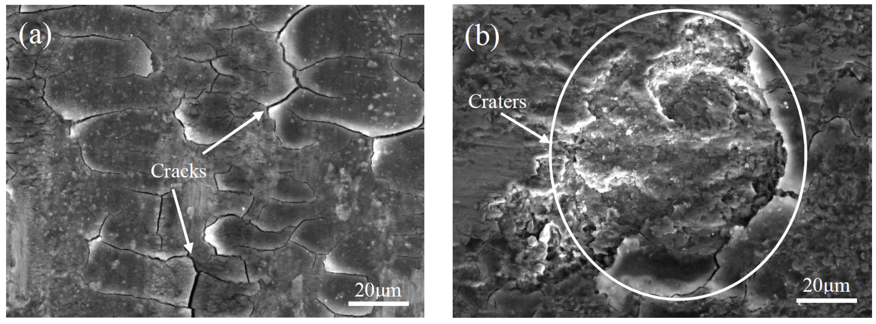
The possible influence of the tribolayer on the wear mechanisms of the coating could be explained by the failure mechanism of the tribolayer. It is observed in Figure 14 that there were two typical defect features related to the failure mechanism: Cracks and craters. Cracks formed on some areas of the tribolayer due to the contact stress produced by the counter-body ball, and the cracks propagated along the interface between the tribolayer and the worn surface of the coating [41], which eventually led to delamination damage and formed craters on the tribolayer. Thereafter, the worn surface zone of the coating previously covered by the tribolayer was exposed again and continued to be worn. In addition, the tribolayer continuously generated on the area where the wear debris accumulated on the wear track surface of the coating, which was a dynamic procedure. The area of the wear track covered by the tribolayer was protected from wear in the subsequent wear process. In view of the analysis of Figure 11b and Figure 13, the material adhered onto the counter-body ball against the coating was mostly tribolayer material. Therefore, it could be known that the tribolayer suffered most of the adhesive wear, so the tribolayer could reduce wear to some extent.
In this subsection, the wear mechanisms of the coatings were analyzed from three aspects: The worn surface morphology of the coatings, the wear debris morphology, and the worn surface morphology of the counter-body balls. It could be comprehensively obtained that the wear mechanisms of the coatings without CeO2 included abrasive wear, adhesive wear, and fatigue wear, and the wear mechanisms of the coatings modified with CeO2 nanoparticles included abrasive wear and adhesive wear. Fatigue wear did not occur on the worn surface of the coatings modified with CeO2 nanoparticles, which was attributed to the CeO2 nanoparticles additive enhancing the toughness of the coating. Hence, the effects of CeO2 nanoparticles on the mechanical properties of the coatings were evident: The coatings modified with CeO2 nanoparticles had higher microhardness, lower wear volume loss, and better wear performance compared to the coatings without CeO2.
4. Conclusions
- Ti-based ceramic coatings on Ti6Al4V substrates were fabricated by laser cladding using TiCN + SiO2 mixed powder with or without adding CeO2 nanoparticles. The composites of the coatings mainly included TiCN, TiN, Ti6O, Ti3SiC2, and α-Ti phase.
- The coatings modified with CeO2 nanoparticles exhibited a better quality of microstructure. The crystalline grain morphology of the upper and middle regions of the coatings without CeO2 was dendrites, while the crystalline grain morphology of the coatings modified with CeO2 nanoparticles was granulated. Moreover, the crystalline grains of the coatings modified with CeO2 nanoparticles were smaller and more compact due to the grain refining effect of the CeO2 nanoparticles.
- The microhardness of the coatings was enhanced significantly compared to the Ti6Al4V substrate. The average values of the microhardness of the coating without CeO2 and the coating modified with CeO2 nanoparticles were approximately 1050 HV0.2 and 1230 HV0.2, respectively.
- The additive of CeO2 nanoparticles obviously improved the wear resistance of the coating under SBF wear test conditions. The wear volume loss of the coating was approximately 2.2% of the wear volume loss of the substrate after a 90-min wear test.
- The wear mechanisms of the coatings without CeO2 included abrasive wear, adhesive wear, and fatigue wear, while the wear mechanisms of the coatings modified with CeO2 nanoparticles included only abrasive wear and adhesive wear, because the refined microstructure of the coatings improved the resistance to fatigue wear.
Author Contributions
Conceptualization, H.W. and D.L.; Methodology, H.W., T.C. and D.L.; Validation, H.W. and T.C.; Formal Analysis, H.W., T.C., W.C. and D.L.; Writing–Original Draft Preparation, H.W., W.C. and D.L.; Writing–Review & Editing, H.W., T.C., W.C. and D.L.
Funding
This research was funded by National Natural Science Foundation of China (No. 51775559).
Acknowledgments
The authors gratefully acknowledge to the technical support from the State Key Laboratory of High Performance Complex Manufacturing and the Light Alloy Research Institute of Central South University.
Conflicts of Interest
The authors declare no conflict of interest.
References
- Habibovic, P.; Li, J.P.; Valk, C.M.V.D.; Meijer, G.; Layrolle, P.; Blitterswijk, C.A.V.; Groot, K.D. Biological performance of uncoated and octacalcium phosphate-coated Ti6Al4V. Biomaterials 2005, 26, 23. [Google Scholar] [CrossRef] [PubMed]
- Romero, C.; Yang, F.; Bolzoni, L. Fatigue and fracture properties of Ti alloys from powder-based processes-A review. Int. J. Fatigue 2018, 117, 407–419. [Google Scholar] [CrossRef]
- Banerjee, D.; Williams, J.C. Perspectives on Titanium Science and Technology. Acta Mater. 2013, 61, 844–879. [Google Scholar] [CrossRef]
- Geetha, M.; Singh, A.K.; Asokamani, R.; Gogia, A.K. Ti based biomaterials, the ultimate choice for orthopaedic implants—A review. Prog. Mater. Sci. 2009, 54, 397–425. [Google Scholar] [CrossRef]
- Budinski, K.G. Tribological properties of titanium alloys. Wear 1991, 289, 203–217. [Google Scholar] [CrossRef]
- Long, M.; Rack, H.J. Titanium alloys in total joint replacement—A materials science perspective. Biomaterials 1998, 19, 1621–1639. [Google Scholar] [CrossRef]
- He, X.J.; Zhang, X.Y.; Wang, X.; Qin, L. Review of Antibacterial Activity of Titanium-Based Implants’ Surfaces Fabricated by Micro-Arc Oxidation. Coatings 2017, 7, 45. [Google Scholar] [CrossRef]
- Rautray, T.R.; Narayanan, R.; Kim, K.-H. Ion implantation of titanium based biomaterials. Prog. Mater. Sci. 2011, 56, 1137–1177. [Google Scholar] [CrossRef]
- Surmenev, R.A. A review of plasma-assisted methods for calcium phosphate-based coatings fabrication. Surf. Coat. Technol. 2012, 206, 2035–2056. [Google Scholar] [CrossRef]
- Santecchia, E.; Hamouda, A.M.S.; Musharavati, F.; Zalnezhad, E.; Cabibbo, M.; Spigarelli, S. Wear resistance investigation of titanium nitride-based coatings. Ceram. Int. 2015, 41, 10349–10379. [Google Scholar] [CrossRef]
- Asri, R.I.M.; Harun, W.S.W.; Hassan, M.A.; Ghani, S.A.C.; Buyong, Z. A review of hydroxyapatite-based coating techniques: Sol-gel and electrochemical depositions on biocompatible metals. J. Mech. Behav. Biomed. 2016, 57, 95–108. [Google Scholar] [CrossRef] [PubMed]
- Kyzioł, K.; Kaczmarek, Ł.; Brzezinka, G.; Kyzioł, A. Structure, characterization and cytotoxicity study on plasma surface modified Ti–6Al–4V and γ-TiAl alloys. Chem. Eng. J. 2014, 240, 516–526. [Google Scholar] [CrossRef]
- Weng, F.; Chen, C.Z.; Yu, H.J. Research status of laser cladding on titanium and its alloys: A review. Mater. Des. 2014, 58, 412–425. [Google Scholar] [CrossRef]
- Chen, T.; Liu, D.F.; Wu, F.; Wang, H.J. Effect of CeO2 on Microstructure and Wear Resistance of TiC Bioinert Coatings on Ti6Al4V Alloy by Laser Cladding. Materials 2018, 11, 58. [Google Scholar] [CrossRef] [PubMed]
- Forn, A.; Picas, J.A.; Fuentes, G.G.; Elizalde, E. Mechanical and tribological properties of TiCxN1−x, wear resistant coatings. Int. J. Refract. Met. H. 2001, 19, 507–513. [Google Scholar] [CrossRef]
- Li, H.T.; Sun, P.F.; Zhu, Y.C.; Wu, M.Z.; Wang, Q. Influence of C2H2 Flows on Microstructure and Corrosion Resistance of TiCN Films Doped with Carbon Atoms. Coatings 2018, 8, 458. [Google Scholar] [CrossRef]
- Peng, Y.; Miao, H.Z.; Peng, Z.J. Development of TiCN-based cermets: Mechanical properties and wear mechanism. Int. J. Refract. Met. H. 2013, 39, 78–89. [Google Scholar] [CrossRef]
- Qi, Y.T.; Shi, H.C.; Zou, Z.D.; Hu, L.P. Microstructure and wear behavior of laser cladding Ni-based alloy composite coating reinforced by Ti(C, N) particulates. China Weld. 2008, 17, 20–23. [Google Scholar]
- Yang, Y.L.; Yan, W.; Zhang, D.; Song, G.Z.; Zheng, Y.R. In Situ-Fabrication of TiCN Ceramic Coating on Titanium Alloy by Laser Cladding Technology. Key Eng. Mater. 2010, 434–435, 485–488. [Google Scholar] [CrossRef]
- Schneider, L.C.R.; Cocks, A.C.F.; Apostolopoulos, A. Comparison of filling behaviour of metallic, ceramic, hardmetal and magnetic powders. Powder Metall. 2005, 48, 77–84. [Google Scholar] [CrossRef]
- Ku, N. Evaluation of the behavior of ceramic powders under mechanical vibration and its effect on the mechanics of auto-granulation. Ph.D. Thesis, Rutgers University, New Brunswick, NJ, USA, 2015. [Google Scholar]
- Ye, H.H.; Rixecker, G.; Aldinger, F. Liquid Phase Sintered SiC with SiO2 Additive. In Ceramics—Processing, Reliability, Tribology and Wear; Müller, G., Ed.; Wiley-VCH Verlag GmbH & Co. KGaA: Weinheim, Germany, 2006. [Google Scholar]
- Stevenson, A.J.; Kupp, E.R.; Messing, G.L. Low temperature, transient liquid phase sintering of B2O3-SiO2-doped Nd: YAG transparent ceramics. J. Mater. Res. 2011, 26, 1151–1158. [Google Scholar] [CrossRef]
- Singh, V.K. Liquid Phase Sintering of Silica. T. Ind. Ceram. Soc. 1981, 40, 44–48. [Google Scholar] [CrossRef]
- Li, J.N.; Chen, C.Z.; Zhang, C.F. Effect of nano-CeO2 on microstructure properties of TiC/TiN +nTi(CN)-reinforced composite coating. B. Mater. Sci. 2013, 36, 541–546. [Google Scholar]
- Zhao, T.; Cai, X.; Wang, S.X.; Zheng, S.A. Effect of CeO2 on microstructure and corrosive wear behavior of laser-cladded Ni/WC coating. Thin Solid Films 2000, 379, 128–132. [Google Scholar]
- Yang, Y.L.; Guo, N.; Li, J.F. Synthesizing, microstructure and microhardness distribution of Ti-Si-C-N/TiCN composite coating on Ti-6Al-4V by laser cladding. Surf. Coat. Technol. 2013, 219, 1–7. [Google Scholar] [CrossRef]
- Graciani, J.; Ma´rquez, A.M.; Plata, J.J.; Ortega, Y.; Herna´ndez, N.C.; Meyer, A.; Zicovich-Wilson, C.M.; Sanz, J.F. Comparative Study on the Performance of Hybrid DFT Functionals in Highly Correlated Oxides: The Case of CeO2 and Ce2O3. J. Chem. Theory Comput. 2011, 7, 56. [Google Scholar] [CrossRef]
- Wang, K.L.; Zhang, Q.B.; Sun, M.L.; Zhu, Y.M. Effect of laser surface cladding of ceria on the wear and corrosion of nickel-based alloys. Surf. Coat. Technol. 1997, 96, 267–271. [Google Scholar] [CrossRef]
- Li, H.C.; Wang, D.G.; Chen, C.Z.; Weng, F. Effect of CeO2 and Y2O3 on microstructure, bioactivity and degradability of laser cladding CaO-SiO2, coating on titanium alloy. Colloid. Surface B 2015, 127, 15–21. [Google Scholar] [CrossRef]
- Zhang, S.H.; Li, M.X.; Cho, T.Y.; Yoon, J.H.; Lee, C.G.; He, Y.Z. Laser clad Ni-base alloy added nano- and micron-size CeO2 composites. Opt. Laser Technol. 2008, 40, 716–722. [Google Scholar] [CrossRef]
- Ding, L.; Hu, S.S. Effect of nano-CeO2 on microstructure and wear resistance of Co-based coatings. Surf. Coat. Technol. 2015, 276, 565–572. [Google Scholar] [CrossRef]
- Feng, W.; Hai, Z.; Yang, S.Z. Nano-indentation and wear-resistance behaviors of TiCN films by pulsed plasma on cemented carbide cutting tool. Mater. Sci. Eng. A 2010, 527, 4767–4770. [Google Scholar] [CrossRef]
- Ghareshabani, E.; Rawat, R.S.; Sobhanian, S.; Verm, R.; Karamat, S.; Pan, Z.Y. Synthesis of nanostructured multiphase Ti(C,N)/a-C films by a plasma focus device. Nucl. Instrum. Meth. A 2010, 268, 2777–2784. [Google Scholar] [CrossRef]
- Seok, M.Y.; Choi, I.C.; Moon, J.; Kim, S.J.; Ramamurty, U.; Jang, J. Estimation of the Hall-Petch strengthening coefficient of steels through nanoindentation. Scripta Mater. 2014, 87, 49–52. [Google Scholar] [CrossRef]
- Li, M.X.; Zhang, S.H.; Li, H.S.; He, Y.Z.; Yoon, J.H.; Cho, T.Y. Effect of nano-CeO2 on cobalt-based alloy laser coatings. J. Mater. Process. Tech. 2008, 202, 107–111. [Google Scholar] [CrossRef]
- Wang, C.L.; Gao, Y.; Zeng, Z.C.; Fu, Y.K. Effect of rare-earth on friction and wear properties of laser cladding Ni-based coatings on 6063Al. J. Alloy. Compd. 2017, 727, 278–285. [Google Scholar] [CrossRef]
- Li, J.; Luo, X.; Li, G.J. Effect of Y2O3 on the sliding wear resistance of TiB/TiC-reinforced composite coatings fabricated by laser cladding. Wear 2014, 310, 72–82. [Google Scholar] [CrossRef]
- Long, S.L.; Liang, Y.L.; Jiang, Y.; Liang, Y.; Yang, M.; Yi, Y.L. Effect of quenching temperature on martensite multi-level microstructures and properties of strength and toughness in 20CrNi2Mo steel. Mat. Sci. Eng. A 2016, 676, 38–47. [Google Scholar] [CrossRef]
- Rynio, C.; Hattendorf, H.; Klöwer, J.; Eggeler, G. On the physical nature of tribolayers and wear debris after sliding wear in a superalloy/steel tribosystem at 25 and 300 °C. Wear 2014, 317, 26–38. [Google Scholar] [CrossRef]
- Anandkumar, R.; Almeida, A.; Vilar, R. Wear behavior of Al-12Si/TiB2, coatings produced by laser cladding. Surf. Coat. Technol. 2011, 205, 3824–3832. [Google Scholar] [CrossRef]
Figure 1.
Schematic diagram of the laser cladding system.
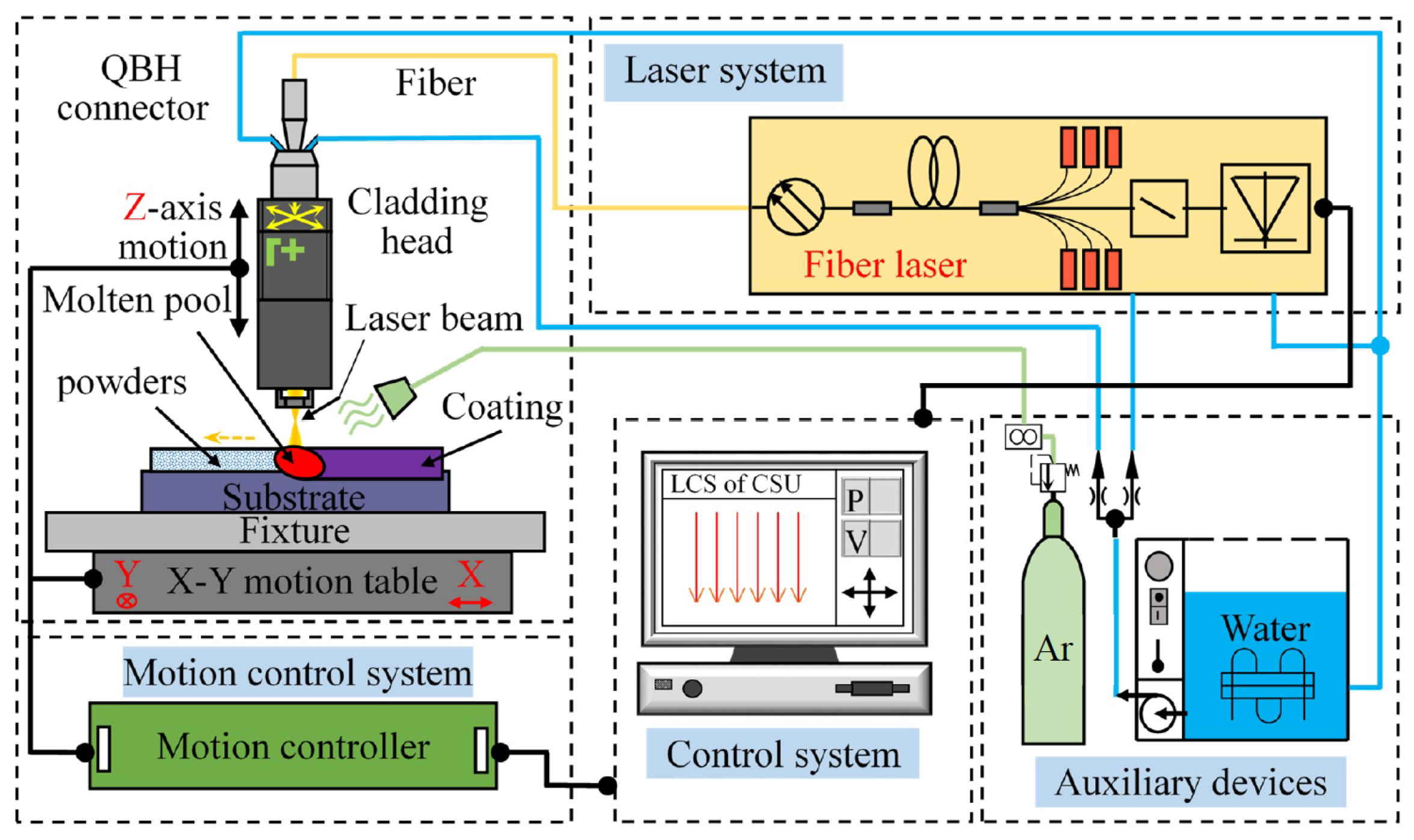
Figure 2.
Schematic illustration of the wear tests for the coatings.

Figure 3.
XRD spectrum patterns of the Ti-based ceramic coatings.

Figure 4.
Typical cross-section morphology of the coating.
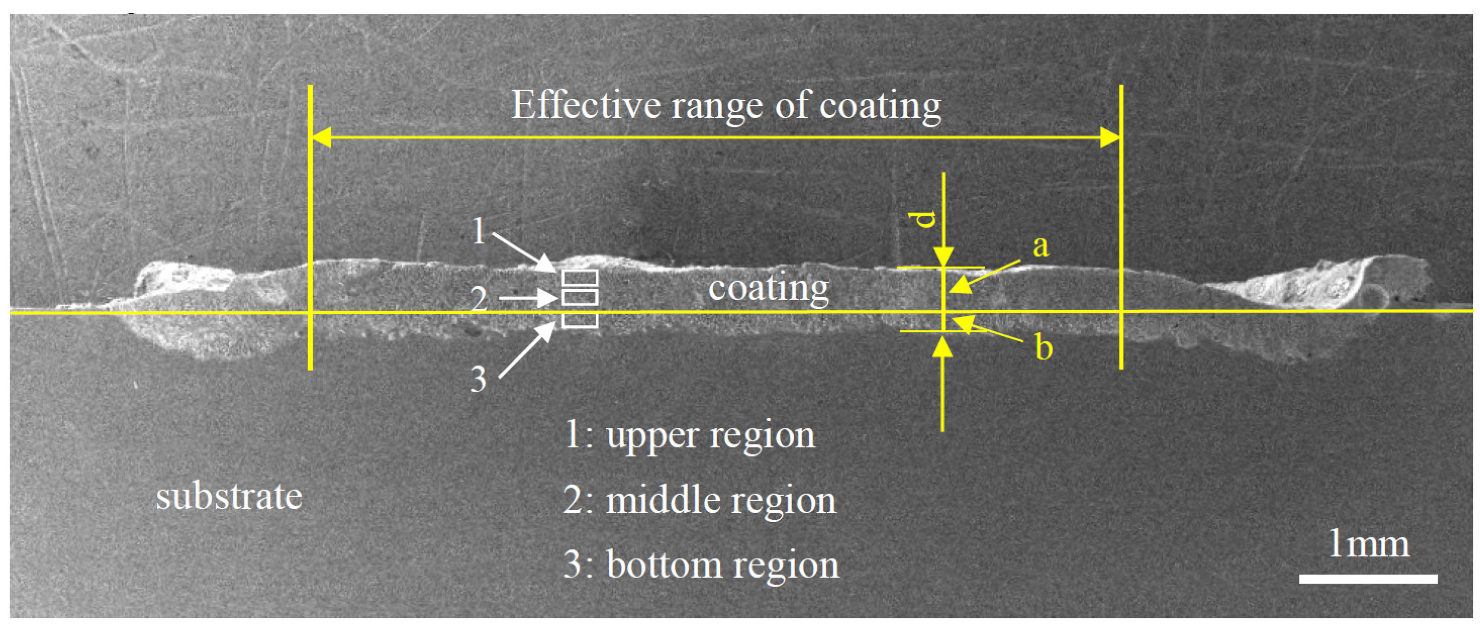
Figure 5.
The cross-section microstructure images of the coatings (a,c,e) without CeO2 and (b,d,f) modified with CeO2: Upper (a,b), middle (c,d), and bottom (e,f) regions of the coatings.
Figure 5.
The cross-section microstructure images of the coatings (a,c,e) without CeO2 and (b,d,f) modified with CeO2: Upper (a,b), middle (c,d), and bottom (e,f) regions of the coatings.
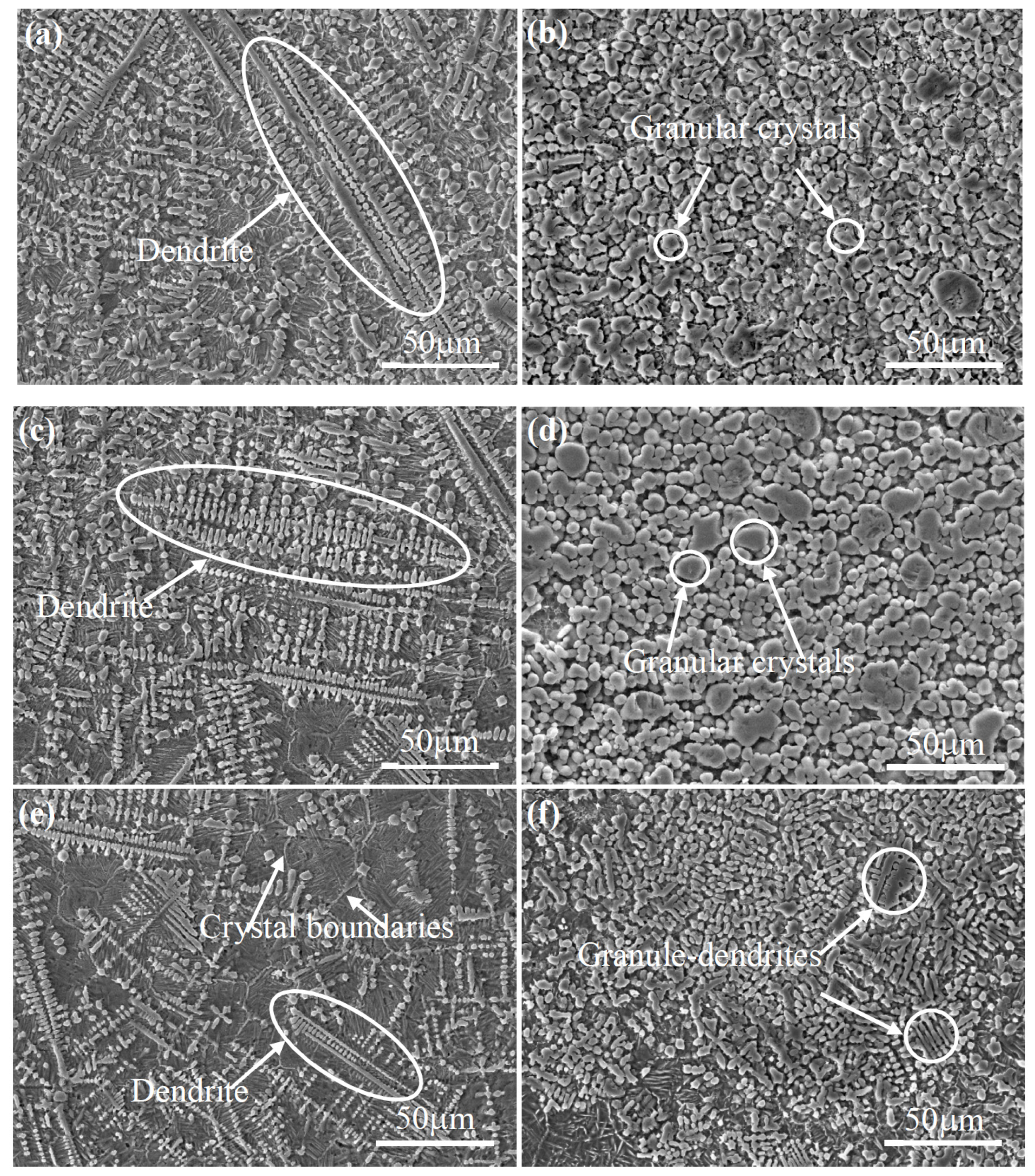
Figure 6.
The EDS results of the typical grains in the coatings (a) without CeO2 and (b) modified with CeO2.
Figure 6.
The EDS results of the typical grains in the coatings (a) without CeO2 and (b) modified with CeO2.

Figure 7.
Microhardness distributions along the depth direction of the coatings without CeO2 and the coatings modified with CeO2 nanoparticles.
Figure 7.
Microhardness distributions along the depth direction of the coatings without CeO2 and the coatings modified with CeO2 nanoparticles.

Figure 8.
Wear volume loss of the Ti6Al4V, the coatings without CeO2, and the coatings modified with CeO2 nanoparticles at different wear times.
Figure 8.
Wear volume loss of the Ti6Al4V, the coatings without CeO2, and the coatings modified with CeO2 nanoparticles at different wear times.

Figure 9.
Typical worn surface morphology images of (a–c) the Ti6Al4V substrate, the coatings (d–f) without CeO2, and (g–i) modified with CeO2 at (a,d,g) 30, (b,e,h) 60, and (c,f,i) 90 min wear time, respectively.
Figure 9.
Typical worn surface morphology images of (a–c) the Ti6Al4V substrate, the coatings (d–f) without CeO2, and (g–i) modified with CeO2 at (a,d,g) 30, (b,e,h) 60, and (c,f,i) 90 min wear time, respectively.

Figure 10.
SEM images of the wear debris of (a) Ti6Al4V, and the coatings (b) without CeO2 and (c) modified with CeO2.
Figure 10.
SEM images of the wear debris of (a) Ti6Al4V, and the coatings (b) without CeO2 and (c) modified with CeO2.

Figure 11.
The worn surface images of the counter-body ball against (a) the Ti6Al4V substrate and (b) the coating modified with CeO2, and the corresponding EDS surface scanning results.
Figure 11.
The worn surface images of the counter-body ball against (a) the Ti6Al4V substrate and (b) the coating modified with CeO2, and the corresponding EDS surface scanning results.

Figure 12.
Typical morphology of (a) the wear track, (b,c) the tribolayer on the worn surface of the coating, and (d) the microtopography of the tribolayer.
Figure 12.
Typical morphology of (a) the wear track, (b,c) the tribolayer on the worn surface of the coating, and (d) the microtopography of the tribolayer.

Figure 13.
EDS line scanning results of the tribolayer. (a) EDS line; (b)Ti; (c)Co; (d) W; (e)Na; (f) Ca; (g) Cl; (h)N; (i) P.
Figure 13.
EDS line scanning results of the tribolayer. (a) EDS line; (b)Ti; (c)Co; (d) W; (e)Na; (f) Ca; (g) Cl; (h)N; (i) P.

Figure 14.
Two typical defect features on the tribolayer: (a) Network cracks and (b) craters.

Table 1.
The ingredients of the pre-placed powder and the corresponding laser cladding coating names.
Table 1.
The ingredients of the pre-placed powder and the corresponding laser cladding coating names.
| Pre-Placed Powder Ingredients (wt %) | Corresponding Laser Cladding Coating Names | ||
|---|---|---|---|
| TiCN | SiO2 | CeO2 | |
| 80 | 20 | 0 | The coatings without CeO2 |
| 77 | 20 | 3 | The coatings modified with CeO2 nanoparticles |
Table 2.
Number of samples required for different tests.
| Test Item | XRD | SEM and EDS | Microhardness Test | Wear Test |
|---|---|---|---|---|
| Sample number | 1 | 3 | 3 | 3 |
Table 3.
The selected parameters for the laser cladding experiments.
| Laser Power (W) | Scanning Speed (mm/s) | Spot Diameter (mm) | Overlap Rate (%) | Argon Flow Rate (L/min) |
|---|---|---|---|---|
| 450 | 7 | 1 | 20 | 10 |
Table 4.
The experimental parameters of the wear tests.
| Wear Time (min) | Load (N) | Rotation Speed (rpm) | Rotation Radius (mm) | Temperature (°C) |
|---|---|---|---|---|
| 30 | 20 | 200 | 5 | 36.5 ± 1 |
| 60 | ||||
| 90 |
© 2019 by the authors. Licensee MDPI, Basel, Switzerland. This article is an open access article distributed under the terms and conditions of the Creative Commons Attribution (CC BY) license (http://creativecommons.org/licenses/by/4.0/).
Share and Cite
MDPI and ACS Style
Wang, H.; Chen, T.; Cong, W.; Liu, D. Laser Cladding of Ti-Based Ceramic Coatings on Ti6Al4V Alloy: Effects of CeO2 Nanoparticles Additive on Wear Performance. Coatings 2019, 9, 109. https://doi.org/10.3390/coatings9020109
AMA Style
Wang H, Chen T, Cong W, Liu D. Laser Cladding of Ti-Based Ceramic Coatings on Ti6Al4V Alloy: Effects of CeO2 Nanoparticles Additive on Wear Performance. Coatings. 2019; 9(2):109. https://doi.org/10.3390/coatings9020109
Chicago/Turabian StyleWang, Haojun, Tao Chen, Weilong Cong, and Defu Liu. 2019. "Laser Cladding of Ti-Based Ceramic Coatings on Ti6Al4V Alloy: Effects of CeO2 Nanoparticles Additive on Wear Performance" Coatings 9, no. 2: 109. https://doi.org/10.3390/coatings9020109
Note that from the first issue of 2016, this journal uses article numbers instead of page numbers. See further details here.