Electrodeposition Behavior of Polycrystalline Ni–Mo–La Composite in Alkaline Solution

1
Xingzhi College, Zhejiang Normal University, Jinhua 321004, China
2
College of Mechanical Engineering & Automation, Fuzhou University, Fuzhou 350116, China
*
Author to whom correspondence should be addressed.
Coatings 2018, 8(9), 299; https://doi.org/10.3390/coatings8090299
Submission received: 7 June 2018
/
Revised: 9 August 2018
/
Accepted: 12 August 2018
/
Published: 24 August 2018
(This article belongs to the Special Issue Nanocomposite Coatings)
Abstract
:The polycrystalline Ni–Mo–La composite coating was obtained by electrodeposition through the addition of La3+ ions into Ni, Mo ions main salt weak alkaline solution. The obtained composite contain 0.92 at.% La. According to the law of ionic activity, the redox reaction of three kinds of metal atoms was studied by polarography and cyclic voltammetry. It was found that the addition of lanthanum ions changed the composite structural, phase, and element, and the OH− ions were deduced during the electrodeposition in alkaline solution. The introduction of lanthanum and molybdenum ions negatively shifted the reduction potential of nickel ions and broadened the peaks significantly in the deposition process, retarding the reduction and deposition rate of Ni ions, which was characterized by a multi-step reduction process of Mo and La metal atoms.
1. Introduction
China is among the countries with relatively rich rare earth reserves. For a long time, China has always attached great importance to the development and utilization of rare earth elements and has made substantial returns in industrial and agricultural products. China has become the world’s largest producer, consumer, and exporter of rare earth products. Rare earth elements have an under-filled outer electron structure and their activity is high. A wide range of electron energy levels in the rare earth-containing composites is apt to be generated. The preparation conditions should be controlled strictly. Among the various types of rare earth materials, functional materials are mainly researched [1,2,3,4,5]. Energetic materials researches show that energetic materials containing lanthanum (La) and cerium (Ce) can absorb a large amount of hydrogen, so that they can be used as hydrogen storage materials [6,7,8], which will be helpful for the development and utilization of new energy sources. It is well known that when the rare earth elements interact with other metals, they are easy to become +3 valence ions, and combine with other atoms, but can show +1 valence ion or other transition valence state, and form different structures of the alloy materials. Since the reduction potential of lanthanum is more negative, the pure metal cannot be obtained by the electro-reduction method in the aqueous solution system. Therefore, the La-modified alloy has been extensively studied. Among the electrolytic cathode materials, rare earth La element generally is used to improve the structure and the chemical activity of the materials. The Ni–La alloy that was prepared by Liu et al. [3] through electrodeposition showed that La–H structure is formed in the alloy, which improved the hydrogen evolution catalytic activity of the alloy electrode. Based on the above, the Ni–Mo–La composite was prepared in the same way as in [4,5]. La–Ni–Mo catalysts for hydrogen production have been studied to verify its activity [1,2,3], effect of La, Mo content on the microstructures, and electrochemical performances of La–Mg(Al)–Ni–Mo hydrogen storage alloys was also studied to verify the rear earth elements activity on the formed composites [7,8,9]. In order to understand its catalytic activity, it is necessary to discuss the formation process and formation mechanism. So our group prepared the amorphous/nanocrystalline Ni–Mo–La composite by electrodeposition and studied the electrochemical activity of the composite [4,5]. The results showed that the Ni–Mo–La composite electrode has higher catalytic activity of hydrogen evolution than Ni–Mo alloy electrode, so that its over-potential of hydrogen evolution is lower. Electrochemical impedance spectroscopy (EIS) impedance experiments showed that the alloy has the characteristics of hydrogen storage material. The hydrogen evolution process is hydrogen absorption—hydrogen storage—desorption. In order to find out the precipitation and the formation mechanism of this kind of composite, the deposition process of the three-element was studied by polarography and cyclic voltammetry.
2. Materials and Methods
2.1. Experimental Materials and Preparation
The electrolyte was prepared with double distilled water and all of the analytical reagents were of analytical grade (Sinopharm Chemical Reagent Beijing Co., Ltd., Beijing, China). The main component content was given separately as 40.0 g·L−1 NiCO3·2Ni(OH)2·4H2O, 10.0 g·L−1 Na2MoO4·2H2O, 48 g·L−1 Na3C6H5O7·H2O, 1.6g·L−1 LaCl3·nH2O, 20.0 g·L−1 NaCl, 24 mL·L−1 NH3·H2O, 20.0 g·L−1 additives (6.0 g·L−1 ascorbic acid, 4.0 g·L−1 sodium dodecyl benzene sulfonate, 10.0 g·L−1, and ethylenetetraaminetetraacetic acid). The additives were prepared ourselves. Deposition conditions: pH is 10.0 ± 0.2, adjusted with 5% ammonium citrate solution. Current density was 5–6 A·dm−2, temperature is 33 ± 2 °C, bath temperature was controlled by DF-101S collector magnetic heating stirrer (Handan Dawei Electroplating Equipment Co. LTD., Handan, China). The deposition time was 30 min. The polarization and cyclic voltammetry time was 3 min. In the process of electrodeposition, pure nickel plate was used as anode (wNi = 99.99%) with copper plate as the cathode. The surface area ratio between cathode and anode was 1:4, separated by 2.5–3.0 cm, submerged at the depth of 5–6 cm parallel to each other. Before electrodeposition, the oxide film on the surface of the sample was removed. Epoxy resin was sealed on the back of the cathode. Then, the samples were degreased and activated with acetone and 10% dilute hydrochloric acid and 10% dilute nitric acid mixed solution and rinsed with distilled water.
2.2. Experimental Characterization
A three-electrode system was used with a saturated calomel electrode as the reference electrode and a platinum electrode as the counter electrode. The copper plate substrate was used for the working electrode for the deposition-reduction process. The reduction peak potential and energy consumption of ions were measured by the polarography method. The reference working electrode is a HMDE (hanging mercury drop electrode, SHY-217, Wuhan Gaoss Union Technology Co. LTD., Wuhan, China), as it was used in the paper [10]. The electrolyte was composed of nickel salt, molybdate and lanthanum chloride at a temperature of 33 ± 2 °C. Cyclic voltammetry was used to determine the micro-reaction on the surface of the electrode, intermediates, the adsorption at the phase boundaries, or the possibility of the formation of a new phase with a scanning speed of 5 mV/s. The working electrode was the deposited Ni–Mo–La composite electrode with an area of 1 cm2 (the electrode back was sealed with epoxy resin) to test the electrochemical properties of the obtained composites. The electrolyte concentration was 7 mol·L−1 NaOH solution at a temperature of 33 ± 2 °C. The electrode reaction parameters were measured to determine the reversibility of the electrode reaction with the scanning speed of 5 mV/s. French Bio-logic electrochemical workstation (MTZ-35, EC-Lab Ltd., Berkshire, French) was utilized while using the matching Electrochemical Workstation software system (EC-Lab) to analyze the data.
The surface morphology of the alloy deposited at the substrate were characterized by S-4800 high-resolution field emission scanning electron microscope (Hitachi S-4800, 15 kV), manufactured by Hitachi, Tokyo, Japan. The composition was determined by using an energy dispersive spectrometer (EDS) component analyzer. The deposited coating materials were peeled off from the substrate and grinded to powder. The phase components and structure of the coating were measured by SMART APEX II single crystal X-ray diffractometer (Bruker SMART APEX II, BrukerSmart, Rheinstetten, Germany). The peeled coating plasma thinning to 90 nm specimen was placed in capsules contained embedding medium and heated at 70 °C for about 9 h. The specimen sections were stained by uranyl acetate and alkaline lead citrate for 15 min, respectively, and observed in transmission electron microscope (TEM) of Model JEOL 2100F (Japan Eletron Optics Laboratory Co., LTD., Tokyo, Japan).
3. Composition and Structure of Coating
The XRD (X-ray diffraction, Philips PW3040/60, PANalytical B.V., Eindhoven, The Netherlands) diffraction patterns of the obtained coating are shown in Figure 1. The content of the atomic components in the coating measured, as shown in Table 1, by EDS is separately Ni 82.94%, Mo 17.06% for Ni–Mo solution system and Ni 74.05% and Mo 25.03%, La 0.92% for Ni–Mo–La solution system. The author’s previous research results had shown that with the existence content of La ions, the atomic percentages of Mo and La atoms gradually increase and the content of Ni atoms gradually decreases [4,5]. This can be defined as Ni–Mo–La ternary composite coating with the coexistence of Ni, Mo, and La three elements, which may be consistent with the three elements induced co-deposition [10,11,12,13,14,15]. The diffraction pattern of the composite shows a strong diffraction peak at near 2θ ≈ 43°, which belongs to the Ni–Mo composite from the coating (PDF Card-00-048-1745 Ni–Mo, A Powder Diffraction File (PDF) Card displays all of the scientific and bibliographic data available for a particular PDF entry and the composites structure). According to Scherrer’s formula [16],
and the lattice strain e can be calculated by
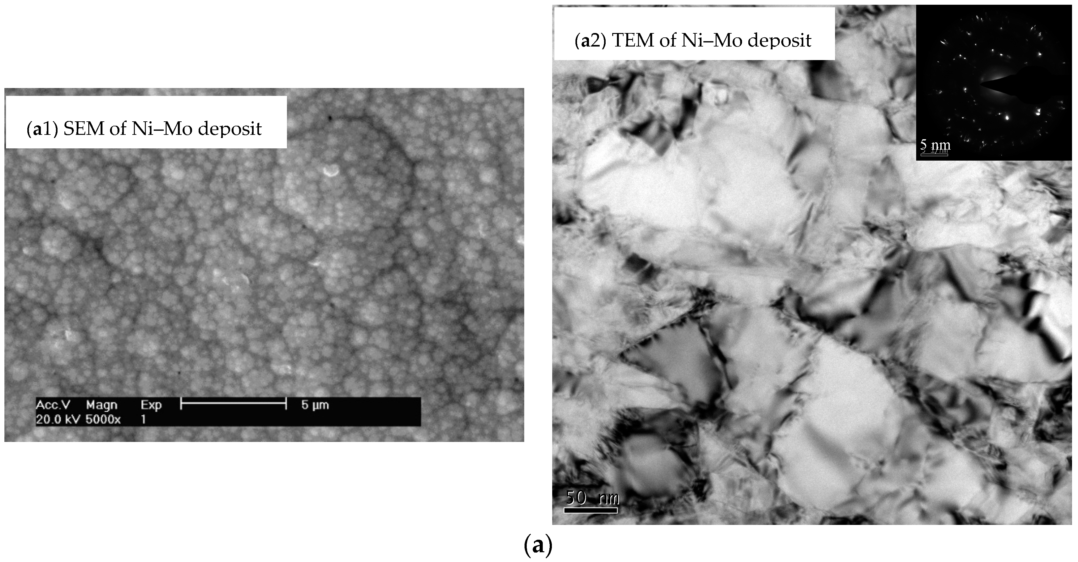
where the diffraction angle is about 2θ ≈ 43.4°, the calculated grain size is about 16.46 nm, and the microstrain is about 0.7614‰ [17]. Due to the addition of La, a diffraction peak near 2θ ≈ 75.6° appears, which may be caused by the newly formed composite composition or related to the micro strain and grain refinement. The cause of this phenomenon may be composed with Lanthanum element affecting on the nickel-molybdenum composites. The formation of new phase or grain refinement will lead to the broadening of diffraction peaks. The surface of the coating sample is scanned by a raster scan, the surface scan area, and the results of composition are shown on the right side of Figure 1. The components of the depositions by EDS show that there is only Ni, Mo, and La existed in the coating, that is to say, most of the deposits structure phases are metal compounds corresponding to the two or three elements. When considering the role and activity of [H] in the deposition process, there may be a corresponding hydrogen compound in the deposits, such as Ni–[H] or La–[H]. Or the active [H] atoms are absorbed in the structure of the metal compounds. Because of relatively higher atom activity and the ability stronger to lose electrons than [H] atoms, the combination of both La and [H] will have the ability to easily adsorb active [H] atoms, while affecting the ternary composite structure and composition of Ni–Mo–La (PDF Card-04-012-1152 La–Ni–Mo–Al). Referring to the literatures [8,9,11,12,13,14,15], the XRD curve and phase composition of the composite show that the composite may contain intermetallic LaNi5 and La2NiMo phase, which strongly adsorb H atoms. The introduction of H atoms makes the grain fine and the formation of a uniform dense coating with a smooth surface and small particles, as shown in Figure 2. Ni–Mo composite surface are covered with the spherical particles, large particles composed of sand-like small particles. The surface morphology of the Ni–Mo–La composite coating is basically similar to the sand-like particles, where the size of the sand seems to be slightly larger than the size of the grit in the Ni–Mo composite large particles. The surface appears slightly rough. From Figure 2(a2,b2), we can find that the TEM test results show that the Ni–Mo–La deposit crystalline grain in the structure is finer than the Ni–Mo deposit, the mixed structure states proportions is expanded. The electron diffraction characteristics indicate that the amorphous structure is more obvious. The results show that the addition of La not only changes the structural composition and the spatial configuration of the composite, but also affects the surface morphology and the deposition mechanism of the coating.
4. Analyses of Ni–Mo/La Composite Deposition Process
4.1. Analysis of Metal Ion Activity
In the electrodeposition process, the reduction oxidation occurs mainly on the surfaces of the cathode and anode. It is known that the ionic radii of La3+, Ni2+, and Mo4+ (Mo6+, Mo3+) are 103 pm, 69 pm, and 65 pm (59 pm, 69 pm), respectively [8,14]. According to the Nernst equation, the reduction potential of them can be calculated as: ΦLa³+ = 0.0261, ΦNi2+ = 0.0290, and ΦMo4+ = 0.0435. Polarography is a type of voltammetry where the working electrode is a HMDE, which is useful for its wide cathodic ranges and renewable surfaces. Figure 3 shows a polarographic diagram of an electrodeposition bath containing Ni2+ ions and Ni2+ in coexistence with MoO42− (4.8 g/L). The peak of [H] at the Lines 1 and 2 is the peak of hydrogen evolution potential. The peak of a and b at the Line 1 are the reduction potential of nickel ions. c, d, e, and f peaks at the Line 2 are the reduction potential of nickel ions and molybdate ions with the addition of molybdate. The hydrogen evolution potential and metal cations reduction potential is negative, which indicates that the required energy for ion reduction is increased. When La ions solution was added (Line 3), there was no obvious peak of hydrogen evolution appeared. The first reduction peak is serious (m peak) width, negative than the nickel ion solution, and the mixed solution with nickel ion and molybdate ions. The second reduction peak (n peak) was also broadened and negative than the others two. The polarization experiment shows that the addition of Mo, La ions increased the reduction potential of Ni ions, and the coexistence of the three elements in solution requires higher energy consumption. As can be seen from the Figure 3 (Curve 1), the hydrogen evolution potential of nickel is about 0.56 V, and there are two polarimetric peaks, it is probably foreseeable that the precipitation of nickel is carried out in two steps. Figure 3 (Curve 2) shows that with the addition of molybdate ions, the polarization peak current increases and the peak potential shifts negatively, indicating that the overpotential required for the electrodeposition process increases and the electric energy consumed increases. Its reduction potential considered, it can be seen that the polarization of Mo4+ is greater than that of Ni2+. When the two elements are present, the acidity of Mo4+ is larger than that of Ni(OH)2. Due to the multivalent presence of Mo, when molybdate ions are added (Curve 2), the peak number increases and the peak current increases in Figure 3. Due to the more negative potential of Mo ions, higher energy is required during the electrodeposition process. Metal Mo atoms are electrodeposited only when the current density exceeds the limiting current density of Mo ions. The introduction of molybdate slowed down the reduction rate of Ni ions and the peak potential increased. Judging from the peak current value of Curve 2, the reduction of MoO42− ions belongs to the multi-step reduction process, corresponding to Mo4+ peak at e and Mo3+ peak at d [19,20,21]. The voltage value shows a delay effect during the formation of the deposition of metal atoms, while the width of the voltage interval provides time for the further deposition of metal atoms. At the same time, MoO3 is soluble in ammonia and alkali metal solution, generating the salt that is corresponding with the isopolyacid. MoO3 often exists as MoO42− in alkaline medium (pH > 10). The pH value of the electrodeposition system will decrease, but it still shows alkalinity (pH > 10) [5]. It indicates that during the electrodeposition reaction, OH− is deduced. Figure 3 (Curve 3) shows that the presence of La ions further retards the reduction of Ni ions and widens and improves the polarization reduction potential. At the same time, the existence of active [H] atoms also affect the nickle molybdenum ions solution systerm, or it combines with the existing of La element to produce new nickel lanthanum compounds. It can be foreseen, during the co-deposition of Ni, Mo, and La, the more complex compounds are formed between Mo4+, Ni2+, and La3+. The polarization ability of Ni2+ is greater than that of La3+. Ni2+ may continue to react with La3+ to generate trace amount of hydrogen storage compounds LaNi5 [10,14,18]. Due to the higher ΦMo6+, the deposition process is easier to happen. Due to the presence of Mo6+, LaNi5 is easily to form the LaNiMo [18,19,20,21], which partially affects the effective synergism between the formed lanthanum and nickel, reduces the ability of the formation of the Ni–La complex compound. Therefore, oxides may also be present in the generated compounds, that is, NiO, MoO2, La2O3, and LaNiOx, etc. [10,11,21,22,23,24], all of which have relatively complicated structural systems. During the reduction process of Mo, it is also likely to be reduced to the +5 state at first during the electron transfer and has a high chemical activity. The overall reduction chemical reaction process is as follows.
4.2. Trimetal Reduction Experiment
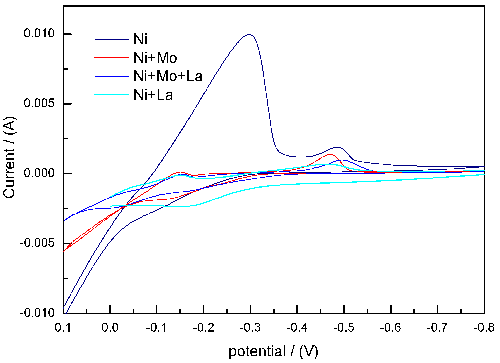
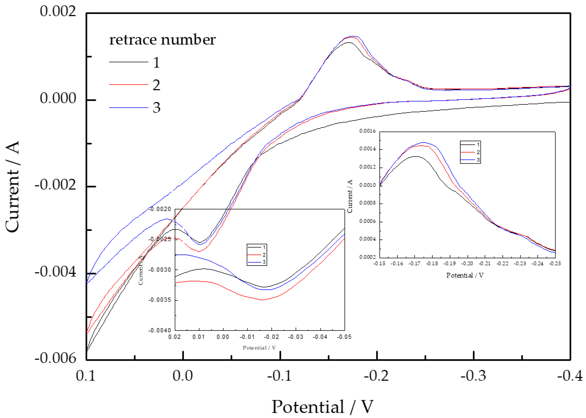
Cyclic voltammetry patterns of the composite solution system with the coexistence of three metal elements ions are shown in Figure 4. It can be seen that, in the electrodeposition process, reduction was easy to happen when pure Ni element solution was deposited on the substrate surface. When the molybdate ion solution was added, the reduction potential negatively shifted and the reduction peak broadened. When the solution containing lanthanum ion was added, the broadening of the reduction peak was more obvious, indicating that the addition of two kinds of metal ions slowed down the deposition rate of nickel ions and there was no obvious current peak in the broadened reduction peak. During the deposition process, the interaction between the ions increases and the synergistic effect between the ions increases. With the addition of two metal ions solutions the oxidation peaks become noticeable. In order to study the effect of La on the elemental Ni and Mo during the metal ions reduction, cyclic voltammetry (CV) experiments were performed on the Ni–La alloy solution system, which are also shown in Figure 4. It can be seen from Figure 4 that La increases the reduction current of Ni2+, and at the same time, broadens the peak of oxidation current. The value of peak oxidation current further increases and the peak broadening becomes serious, indicating that the reduction metal cations need higher energy to satisfy the interaction between atoms, indicating that the La element slows down the reduction of Ni deposition, reducing the current efficiency. In the Ni + La ions solution with the addition of a quantitative molybdate, the cyclic voltammetry patterns are shown in Figure 5. It can be seen that Mo reduces the current peak [3,4,11] and increases the broadening of the current peak, indicating that the reduction process of the three elements is more complicated. The peak current shift indicates that multi-step redox process happens to the polyvalent metal ions in the process of being reduction. Broadening of the reduction peak corresponds to multi-step oxidation peak current value, indicating that the three elements in the reduction process is a multi-step reduction process.
The emergence of multiple position reduction peaks in polarization experiments and broadening reduction peaks in cyclic voltammetry experiments indicate that the high valence metal ions need higher energy to be reduced in the reduction process. The literatures [22,23] show that the high valence ions of molybdate are reduced to the order reduction process, that is, the process of . When La ions exist together with nickel ions, more complex compounds were formed with Ni or H during the reduction process because of the particularity electronic structure of La element. When the three metal ions exist together with each other, more energy consumption was reduced in the metal ions reduction process, and the reduction peak is less obvious. When combined with the description of the literature [24,25,26,27], three metal ions are the multi-step reduction process.
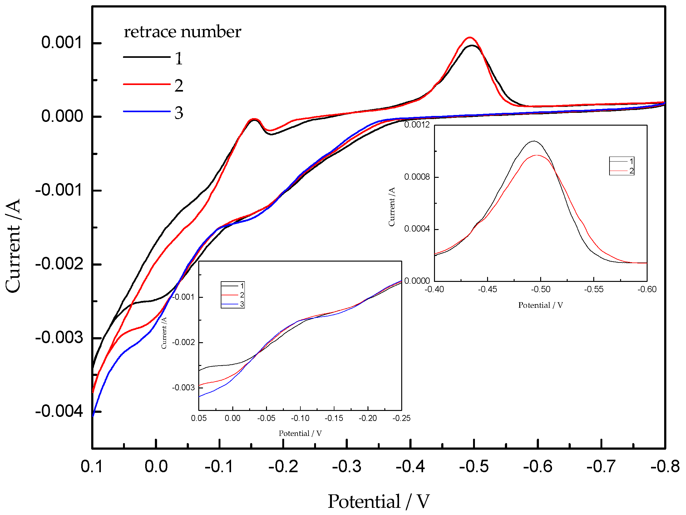
The cyclic voltammetry of the obtained Ni–Mo–La electrode as a cathode in 7 mol/L NaOH solution at 33 °C is shown in Figure 6. As can be seen from Figure 6, with the increase of the number of scanning, oxidation peak potential shifts positively. The reduction peak potential shift negatively, the peak potential difference increases. The reversibility of the electrochemical reaction decreases. The area of the oxidation peak and reduction peak of this composite is bigger. But, in the literatures [5,7,21,22,23] and other studies, it is shown that the oxidation peak area and electrochemical capacity are consistent. This shows that the composites can storage hydrogen to some extent. Oxidation peak potential is about −0.04–0.02 V. The reduction peak potential is about −0.152~−0.250 V. The redox potential difference is small, indicating that the reversible electrochemical hydrogen storage capacity of the composite is good. There is some hydrogen storage structure in the formed composite.
Electrochemical properties and interaction between elements, complexing agents and additives in formation process of the obtained composites from literatures [25,28,29,30,31,32,33,34,35], and the experimental results of electrochemical performance of Ni–Mo–La composite, it has been shown that the oxides that are formed during the multi-step reduction of citrate ions (Cit3−), ammonium ions (NH4+), and metallic cations Ni2+, MoO42−, La3+, and Mo before the metal ions are reduced, such as MoO2, Mo2O, and other complexes are easily adsorbed on the cathode surface, which is related to the direct deposition process after reduced under the cathode current. Chemical reaction process of the complex formation is as follows.
4.3. Co-Deposition Kinetic Analysis
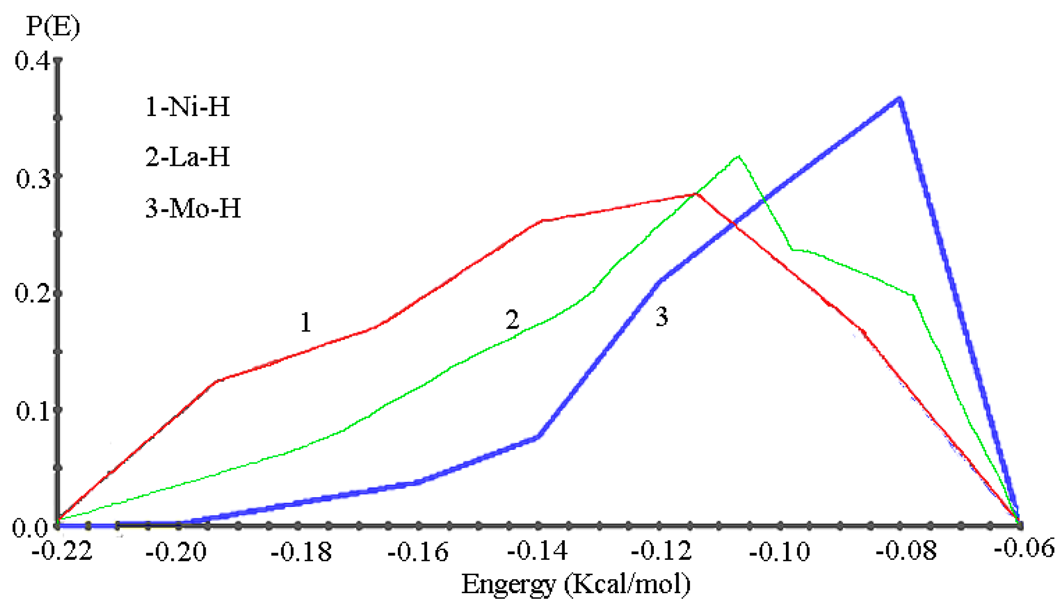
There are many researches on the reduction and deposition process of Ni ions, most of which show that the reduction of Ni element ions forms a reactant (NiOH)+, which discharges on the electrode surface through reaction, and then forms an adsorbed intermediate product (NiOH)ads, which is adsorbed on the cathode surface. The reduction process shall occur if there is the current [11,29]. In the solution of coexistence of Ni and Mo ions, due to the more negative potential of Mo ions, the formation of larger clusters between Mo and with the complex ions in the electrodeposition process, which plays an important role in the entire reduction process and the proportion of elements, affecting the reduction rate of Ni2+. Its adsorption on the electrode surface hinders the reactive sites at the interface between the electrode and the electrolyte, and increases the cathodic polarization of the electrochemical reaction [4,5]. In the electrodeposition process, a matchstick with a spark placed near the electrode has a tendency to burn, indicating that oxygen is the reaction product in the deposition. LAMMPS is a classical molecular dynamics code, and an acronym for Large-scale Atomic/Molecular Massively Parallel Simulator. According to the basis of simulation algorithm model of LAMMPS, bond energies of Ni–H, La–H, Mo–H can be calculated shown in Figure 7. As can be seen from the Figure 7, the bond energy of La–H is higher than Ni–H, and the Mo–H bond shall be much larger than that of La–H bond. Therefore, in the deposition process, once the free [H] is trapped, which is very easily to be kept in the internal space of the deposited coating structure. It is known that the introduction of lanthanum element will further increase the amount of [H] in the internal space [3]. The tiny phase of the deposition that is described in XRD diffraction results and the electrochemical performance experimental results [4,5] show the possibility of the dissociation and capture of active [H] will contribute to the formation of La–Ni–Mo ternary composite. Because there is an empty 4f orbit in La atomic layer electron, and this structure has a strong adsorption capacity. At the same time, La(OH)3 is a double hydroxide, which has the ability of oxidation and reduction. It is shown in the CV curve of the elemental reduction process in the presence of the three elements, when considering the complex ions (Figure 4, Figure 5 and Figure 6), that the deposition process of the composite element is the composite deposition one, that is, the co-deposition of anomalous co-deposition and induced co-deposition [12,22,23,24,25,26,27,28,29]. The electro-deposition process of Ni2+, Mo4+, and La3+ can be described, as follows.
5. Conclusions
- The La3+ ion solution was added into the weak alkaline solution of Ni and Mo ions main salt to obtain the Ni–Mo–La composite. The addition of lanthanum element not only changed the structural composition and the spatial configuration of the composite, also showed some impact on the surface morphology and the deposition mechanism of the coating.
- In the process of electro-deposition of Ni–Mo–La coating in alkaline solution, the OH− ions were reduced. The addition of lanthanum and molybdenum ions negatively shifted the reduction potential of nickel ions and broadened the peak positions, which delayed the reduction of Ni ions speed, thus reducing the current efficiency.
- The polarization patterns and cyclic voltammetry patterns of the reduction deposition show that the electron transfer process of multivalent molybdenum is a step-by-step valance-lowing one.
Author Contributions
Conceptualization, N.L. and C.G.; Methodology, Validation, N.L. and W.C.; Formal Analysis and Investigation, N.L. and C.G.; Data Curation, L.L.; Writing-Original Draft Preparation and Review & Editing, N.L.
Funding
This research received no external funding.
Acknowledgments
Thanks are due to testing center of Fuzhou University and Zhejiang normal university institute of physical chemistry for assistance with the experiments and to Baoxing Xu (University of Virginia) for valuable discussion.
Conflicts of Interest
The authors declare no conflict of interest.
References
- Wang, X.; Cheng, Z.; Jin, Y.; Wu, Y.; Dai, X.; Liu, G. Magneto-electronic properties and tetragonal deformation of rare-earth-element-based quaternary Heusler half-metals: A first-principles prediction. J. Alloys Compd. 2018, 734, 329–341. [Google Scholar] [CrossRef]
- Martins, A.; Silva, J.M.; Ribeiro, M.F. Influence of rare earth elements on the acid and metal sites of Pt/HBEA catalyst for short chain n-alkane hydroisomerization. Appl. Catal. A Gen. 2013, 466, 293–299. [Google Scholar] [CrossRef]
- Yang, Y.; Xu, C.; Hua, Y.; Wang, M.; Su, Z. Electrochemical preparation of Ni–La alloys from the EMIC-EG eutectic-based ionic liquid. Ionics 2017, 23, 1703–1710. [Google Scholar] [CrossRef]
- Gao, C.; Li, N. Hydrogen evolution reaction activity of electrodeposited amorphous/nanocrystalline Ni–Mo–La alloy electrode. Chin. J. Nonferrous Met. 2011, 21, 2819–2824. [Google Scholar]
- Ning, L.; Chenghui, G.; Suzhen, Y. Effects of lanthanum on microstructure and properties of amorphous-nanocrystalline Ni–Mo alloy coating. J. Chin. Soc. Rare Earths 2009, 27, 251. (In Chinese) [Google Scholar]
- Frommen, C.; Sørby, M.H.; Heere, M.; Humphries, T.D.; Olsen, J.E.; Hauback, B.C. Rare earth borohydrides-crystal structures and thermal properties. Energies 2017, 10, 2115. [Google Scholar] [CrossRef]
- Chakrabarti, S.; Biswas, K. Effect on de-hydrogenation efficiency on doping of rare earth elements (Pr, Nd, Gd, Dy) in MgH2—A density functional theory study. Int. J. Hydrogen Energy 2017, 42, 1012–1017. [Google Scholar] [CrossRef]
- Lee, D.; Chen, Y. Hydrogenation of p-chloronitrobenzene on La-doped NiMoB nanocluster catalysts. Chin. J. Catal. 2013, 34, 2018–2028. [Google Scholar] [CrossRef]
- Paschoalino, W.J.; Thompson, S.J.; Russell, A.E.; Ticianelli, E.A. The borohydride oxidation reaction on La-Ni-based hydrogen-storage alloys. Chemphyschem 2014, 15, 2170–2176. [Google Scholar] [CrossRef] [PubMed]
- Kemula, W.; Kublik, Z. Application de la goutte pendante de mercure à la détermination de minimes quantités de différents ions: Communiqué préliminaire. Anal. Chim. Acta 1958, 18, 104–111. [Google Scholar] [CrossRef]
- Zeng, Y.; Yu, S.; Li, Z.; Chen, K.; Zhou, S. Kinetic model of ethanol oxidation on Ni–Mo alloy electrode. Acta Phys. Chim. Sin. 2000, 16, 1013–1021. [Google Scholar] [CrossRef]
- Wu, D.; Liang, G.; Li, L.; Wu, H. Microstructural investigation of electrochemical hydrogen storage in amorphous Mg–Ni–La alloy. Mater. Sci. Eng. B 2010, 175, 248–252. [Google Scholar] [CrossRef]
- Paul, M.S. Electrodeposition of thin-film rare-earth-metal oxocuprates. J. Mater. Chem. 1996, 6, 183–186. [Google Scholar] [CrossRef]
- Herbst, J.F.; Hector, L.G., Jr. La(TM)5 hydrides (TM = Fe, Co, Ni): Theoretical perspectives. J. Alloys Compd. 2007, 446–447, 188–194. [Google Scholar] [CrossRef]
- Huang, Z.; Li, J.; Rao, Q.; Zhou, Y. Effects of La content on the glass transition and crystallization process of Al–Ni–La amorphous alloys. Intermetallics 2007, 15, 1139–1146. [Google Scholar] [CrossRef]
- Scherrer, P. Bestimmung der Größe und der inneren Struktur von Kolloidteilchen mittels Röntgenstrahlen. In Kolloidchemie Ein Lehrbuch; Zsigmondy, R., Ed.; Springer-Verlag: Berlin, Germany, 1918; pp. 98–100. [Google Scholar]
- Spiller, E. X-ray optics. In Encyclopedia of Optical Engineering; Driggers, R.G., Hoffman, C., Driggers, R., Eds.; CRC Press: Boca Raton, FL, USA, 2003; pp. 3042–3048. [Google Scholar]
- Kuang, W.; Fan, Y.; Chen, Y. Structure and reactivity of ultrafine Ce–Mo oxide particles. Catal. Today 2001, 68, 75–82. [Google Scholar] [CrossRef]
- Jiang, C.; Yang, Z.; Xiang, L.; Shang, J.; Cheng, M.; Min, D. Dose-dependent effects of lanthanum chloride on wear particle-induced aseptic inflammation in a murine air-pouch model. J. Rear Earths 2013, 4, 420–427. [Google Scholar] [CrossRef]
- Wang, W.; Zhang, X.; Yang, Y.; Yang, Y.; Peng, H.; Luo, H. Preparation of La–Ni–Mo–B amorphous catalyst and its catalytic properties for hydrodeoxygenation of phenol. Acta Phys. Chim. Sin. 2012, 28, 1243–1251. [Google Scholar]
- You, Y.; Yan, M. Behaviors and interactions of La atom with other foreign substitutional atoms (Al, Si, Ti, V, Cr, Mn, Co, Ni, Cu, Nb or Mo) in iron based solid solution from first principles. Comput. Mater. Sci. 2013, 73, 120–127. [Google Scholar] [CrossRef]
- Terashima, M.; Takada, N.; Saga, H.; Kohn, K. Metallic conductivity of the oxides of La–Ni–O system. Phase Transit. 1993, 41, 123–128. [Google Scholar] [CrossRef]
- Lačnjevac, U.; Jović, B.M.; Baščarević, Z.; Maksimović, V.M.; Jović, V.D. Morphology and phase composition of as-deposited and recrystallized Ni–Mo–O powders. Electrochim. Acta 2009, 54, 3115–3123. [Google Scholar] [CrossRef]
- Zeng, L.; Xiao, L.; Xiao, C.; Gong, B. Study on leaching of molybdenum and nickel from Ni–Mo ore using sodium chlorate. Can. Met. Q. 2013, 52, 335–341. [Google Scholar] [CrossRef]
- De la Torre, A.I.; Banda, J.A.; García, U.P.; Alvarado, D.I.; García, M.A.; Martínez, B.P. Crystallographic properties of the unsupported Ni–Mo carbides phases. Adv. Mater. Phys. Chem. 2013, 3, 206–208. [Google Scholar] [CrossRef]
- Li, Y.; Tao, Y.; Ke, D.; Yang, S.; Han, S. Facile synthesis of Mo–Ni particles and their effect on the electrochemical kinetic properties of La–Mg–Ni-based alloy electrodes. J. Alloys Compd. 2014, 615, 91–95. [Google Scholar] [CrossRef]
- Wang, W.; Yang, Y.; Luo, H.; Liu, W. Effect of additive (Co, La) for Ni–Mo–B amorphous catalyst and its hydrodeoxygenation properties. Catal. Commun. 2010, 11, 803–807. [Google Scholar] [CrossRef]
- Gangopadhyay, A.K.; Kelton, K.F. Effect of rare-earth atomic radius on the devitrification of Al88Re8Ni4 amorphous alloys. Philos. Mag. 2000, 80, 1193–1206. [Google Scholar] [CrossRef]
- Suran, F.; Lemin, L. Determination of the stability constants of rare earth-tetracycline-citric (malic, tartaric, salicylic) acids mixed ligand complexes. In New Frontiers in Rare Earth Science and Applications; Xu, G., Xiao, J., Eds.; Academic Press: Cambridge, MA, USA, 1985; pp. 127–130. [Google Scholar]
- Gómez, E.; Pellicer, E.; Vallés, E. Influence of the bath composition and the pH on the induced cobalt-molybdenum electrodeposition. Electroanal. Chem. 2003, 556, 137–145. [Google Scholar] [CrossRef]
- Chen, Q.; Chen, M.; Mao, S.; Zhou, Z. Progress in coordinated structural chemistry to citrate process. Sci. Sin. Chim. 2011, 41, 645–653. [Google Scholar] [CrossRef]
- Yang, J.B.; Tai, C.Y.; Marasinghe, G.K.; Waddill, G.D.; Pringle, O.A.; James, W.J.; Kong, Y. Structural, electronic and magnetic properties of LaNi5−xTx (T = Fe, Mn) compounds. Phys. Rev. B 2001, 63, 4407–4440. [Google Scholar] [CrossRef]
- Yang, J.B.; Tai, C.Y.; Marasinghe, G.K.; Waddill, G.D.; Pringle, O.A.; James, W.J. Electronic structures and magnetism of LaNi5−xFex compounds. J. Appl. Phys. 2001, 89, 7311–7313. [Google Scholar] [CrossRef]
- Dias, C.; Pessine, E.J. The electrochemical behaviour of La3+ over Ni and Mo, in molten salts chloride. In Hydrogen Materials Science and Chemistry of Metal Hydrides; Hampton, M.D., Schur, D.V., Zaginaichenko, S.Y., Trefilov, V.I., Eds.; Springer: Dordrecht, The Netherlands, 2002; pp. 349–356. [Google Scholar]
- Şahin, Ö.; Ekinci, A.; Balbay, A.; Saka, C. Effects of plasma treatment, La content and temperature on the La–Ni–Mo–B catalysts for hydrogen production from NaBH4 hydrolysis. Surf. Eng. 2017, 33, 499–505. [Google Scholar] [CrossRef]
Figure 1.
XRD and EDS patterns of the deposit (a) Ni–Mo alloy and (b) Ni–Mo–La composite.
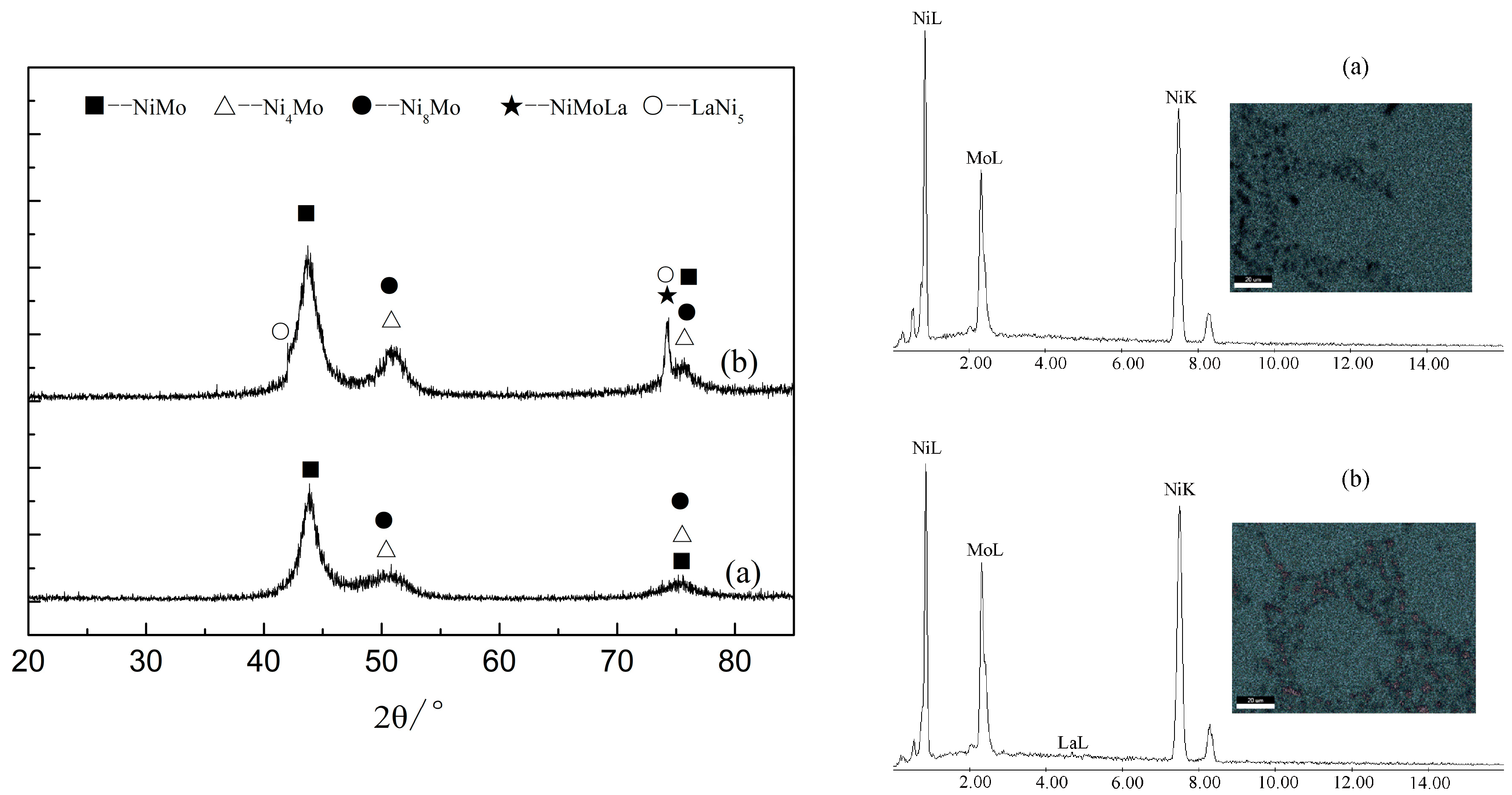
Figure 2.
SEM and TEM images of the deposited (a) Ni–Mo and (b) Ni–Mo–La.

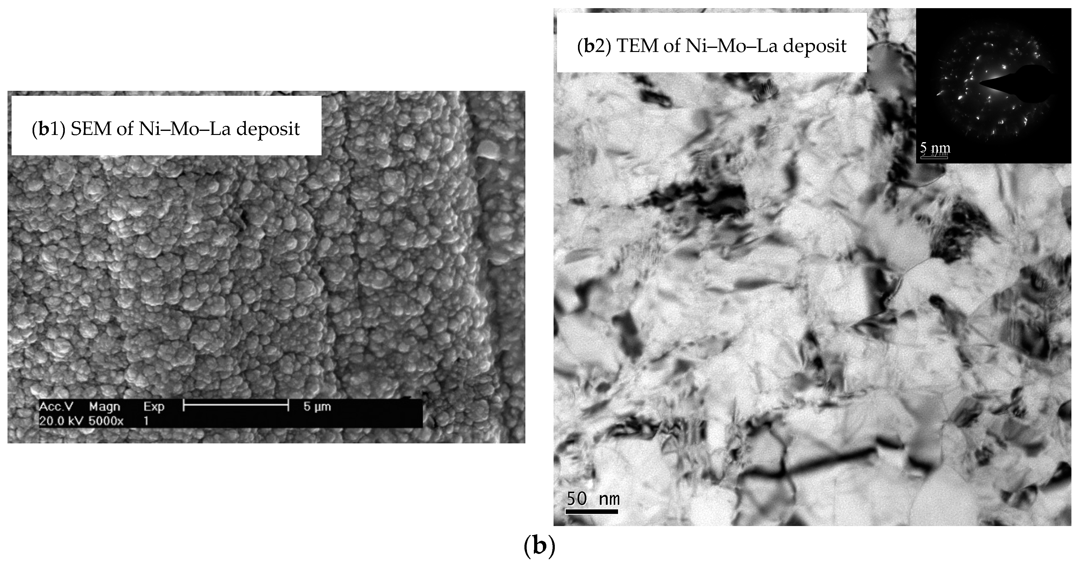
Figure 3.
The polarogram of the solutions with Ni2+ or Ni2+ + MoO42− or Ni2+ + MoO42− + La3+ co-existence.
Figure 3.
The polarogram of the solutions with Ni2+ or Ni2+ + MoO42− or Ni2+ + MoO42− + La3+ co-existence.
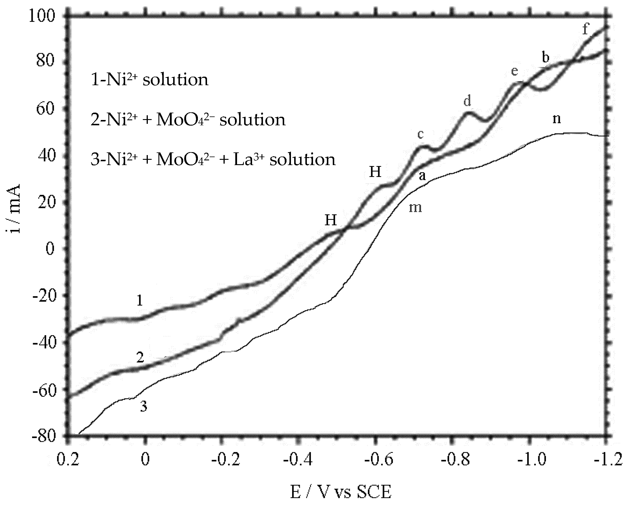
Figure 4.
Cyclic Voltammetry (CV) of cathodes deposit solution with Ni, Mo, La ions, respectively (33 ± 2 °C).
Figure 4.
Cyclic Voltammetry (CV) of cathodes deposit solution with Ni, Mo, La ions, respectively (33 ± 2 °C).

Figure 5.
CV of cathode in the same Ni, La, Mo concentration solution. (40.0 g·L−1 Ni2+ + 1.6 g·L−1 La3+, 10.0 g·L−1 MoO42− additional satiation, 33 ± 2 °C).
Figure 5.
CV of cathode in the same Ni, La, Mo concentration solution. (40.0 g·L−1 Ni2+ + 1.6 g·L−1 La3+, 10.0 g·L−1 MoO42− additional satiation, 33 ± 2 °C).

Figure 6.
CV of Ni–Mo–La cathode in 7 mol/L NaOH solution (33 ± 2 °C).

Figure 7.
Energy distribution of Ni, Mo, La atomistic with H atomistic.


Table 1.
The content of the atomic components in the deposited composites.
| Element Content | ρ (La) (g/L) | W (Ni) (at.%) | W (Mo) (at.%) | W (La) (at.%) |
|---|---|---|---|---|
| Ni–Mo | 0 | 82.94 | 17.06 | 0 |
| Ni–Mo–La | 1.6 | 74.05 | 25.03 | 0.92 |
© 2018 by the authors. Licensee MDPI, Basel, Switzerland. This article is an open access article distributed under the terms and conditions of the Creative Commons Attribution (CC BY) license (http://creativecommons.org/licenses/by/4.0/).
Share and Cite
MDPI and ACS Style
Li, N.; Chen, W.; Lu, L.; Gao, C. Electrodeposition Behavior of Polycrystalline Ni–Mo–La Composite in Alkaline Solution. Coatings 2018, 8, 299. https://doi.org/10.3390/coatings8090299
AMA Style
Li N, Chen W, Lu L, Gao C. Electrodeposition Behavior of Polycrystalline Ni–Mo–La Composite in Alkaline Solution. Coatings. 2018; 8(9):299. https://doi.org/10.3390/coatings8090299
Chicago/Turabian StyleLi, Ning, Weizeng Chen, Lirong Lu, and Chenghui Gao. 2018. "Electrodeposition Behavior of Polycrystalline Ni–Mo–La Composite in Alkaline Solution" Coatings 8, no. 9: 299. https://doi.org/10.3390/coatings8090299
Note that from the first issue of 2016, this journal uses article numbers instead of page numbers. See further details here.