Novel Coatings on Zirconia for Improved Bonding with Veneer Ceramics


1
School of Stomatology, China Medical University, Shenyang 110002, China
2
School of Clinical Dentistry, The University of Sheffield, Sheffield S10 2TA, UK
3
Materials Science and Engineering Department, Northeastern University, Shenyang 110004, China
*
Author to whom correspondence should be addressed.
Coatings 2018, 8(10), 363; https://doi.org/10.3390/coatings8100363
Submission received: 5 August 2018
/
Revised: 16 September 2018
/
Accepted: 19 September 2018
/
Published: 12 October 2018
Abstract
:This study aimed to compare the effects of two surface-coating methods on the shear bond strength (SBS) of veneering ceramics (VC) to zirconia. Eighty pre-sintered zirconia cubes were randomly assigned into four study groups: E60S, E60P, N60S, and N60P. The zirconia surface was coated with a mixture of two types of glaze and alumina (<60 μm) by airbrush spraying and fine- brush painting. Surface roughness (Ra), X-ray diffraction (XRD), scanning electron microscopy (SEM), energy dispersive spectroscopy (EDS), and SBS measurements (both initial and artificial aged conditions, including one month of water storage) were performed. The Ra results revealed significant differences among all groups (p < 0.001). The N60P group exhibited higher values of Ra (5.717 ± 0.20 µm) and SBS before and after water storage with values of 37.22 ± 4.954 MPa and 34.42 ± 3.977 MPa, respectively. The fine-brush coatings showed significantly higher SBS than that of airbrush coatings, in both initial and artificial conditions. Both coating methods and various coating materials (p < 0.001) produced a significant influence on VC-zirconia SBS. A significant correlation between Ra and SBS (Spearman’s rho = 0.808; p < 0.001) was found. The novel coating by fine-brush painting is a promising surface treatment and an easy technique for obtaining a rougher surface, which subsequently improves the bond strength to VC.
1. Introduction
An increasing demand for aesthetics and advancements in technology contributes to the rise in popularity of all-ceramic restorations. In the last two decades, the fabrication of high-strength materials results from the continuous progress in ceramic material science for dental applications. The improvement of zirconia-based ceramics provides acceptable fracture resistance and long-term viability compared with silica-based materials [1]. These properties induce the utilization of zirconia in a variety of dental applications, such as in fixed partial dentures (FPDs) [2,3].
Recently, zirconia was introduced to the family of dental ceramics. Its superior mechanical properties render it suitable for substructure, and it can be widely used for single- and multi-unit FPDs [4]. Zirconia, specifically yttria-stabilized tetragonal zirconia polycrystal (Y-TZP), became favored as a core material for all-ceramic restorations because of its high mechanical strength and toughness [5]. On the contrary, zirconia copings for crowns or multi-unit frameworks still require the application of porcelain ceramics, typically specialized porcelain, to achieve appropriate aesthetics [6].
Zirconia-based core structures are veneered with zirconia veneering ceramics (VC), which generally consist of an amorphous and glassy silica matrix embedded in varying amounts of feldspar and leucite crystals [7]. Although the Y-TZP substrate displays excellent mechanical properties, veneer chipping (debonding) [8] is described in clinical service with a failure rate of 15% after 2–5 years [6], and 21–23% after 5–10 years of service due to poor bond strength to veneering [9]. This property is mainly due to the chemical stability of Y-TZP, whereby no inherent glass content is detected in the matrix, and a nonpolar covalent bond exists [10]. The bond strength between the Y-TZP core and VC is determined by the cumulative effects of various factors, such as chemical bond strength, mechanical interlocking, firing shrinkage of VC, type and concentration of defects at the interface, and wetting properties of the core by VC. The adhesion between the zirconia core and VC is affected by the degree of compressive stress in the veneering layer due to a difference in the coefficients of thermal expansion (CTE) between zirconia and VC [10,11,12,13,14]. Zirconia surface treatment techniques were developed to enhance bond strength and increase the Ra and energy, thus directly improving the wetting and the bonding properties between the zirconia and VC [15]. Various surface-conditioning methods of the zirconia substructure were researched to achieve enhanced zirconia/VC bonding. Among these methods, airborne-particle abrasion with Al2O3 particle sizes in the range of 30–125 µm [16], with or without silica coating [17], liner application [14], laser etching [18], and argon plasma treatment [19] are all used alone or in association. Airborne-particle abrasion is recommended for zirconia surface modification because of its significant effect on bond strength. However, this method may promote phase transitions at the surface, thereby altering the crystal structure of zirconia from tetragonal to monoclinic [6], which is accompanied by stress generation on the veneering layer and reverses the bonding strength to the zirconia substrate [20]. The liner application was found to be affected by thermal cycling, which inversely compromises the bond strength between zirconia and VCs [9]. The application of a CO2 laser induces zirconia surface remodeling and promotes Ra. However, high Ra does not result in high shear bond strength (SBS) [18]. Argon plasma cleaning improves the bond between ceramic and zirconia surfaces. However, when plasma cleaning was followed by a glassy liner application, the zirconia/VC bond was significantly reduced [19]. Previous studies applied glaze as the coating material, using a glaze-on technique on the fitting surface (inner side) of the zirconia restoration [21], or mixed with partially crystallized zirconia particles and applied on the core surface [20] to improve the bonding strength. Results showed that the glazing technique remarkably improved the SBS of the resin-based cement [21] and VC in the composite form [20].
Alumina or Al2O3 is used in dentistry for anterior and posterior crowns, veneers, onlays, inlays, and short-span bridge restorations in all locations of the oral cavity [22]. Previous investigations were performed using nano-alumina coating (Al) for resin cementation of zirconia by immersing the zirconia specimen in 3 wt % dilute aluminum nitride solution and heating it, resulting in remarkably increased Ra and flexural bond strength between the Y-TZP ceramic and various dual-cured resin cements of zirconia [23,24,25,26]. Surface treatment with pre-sintered zirconia of different particle sizes was performed by airbrush spraying [20] and the commonly used fine-brush paint coating [27].
The airbrush spraying method is an advanced coating process, which is used for the surface modification of all ceramic [20,28,29] and bioceramic materials [30]. The airbrush spraying of powder suspensions is a versatile method that allows the coating of differently shaped substrates, such as flat [20] or curved [30], substrates with adequate control of the thickness [29]. Easily evaporable alcoholic-based carriers are often used to obtain high-flowing solutions [29]. This technique is an effective method that improves the control of coating applications, thereby achieving continuous planes and a rough surface [20]. Previous studies used composite zirconia/glaze materials as the coating material with the airbrush spraying approach, which consists of applying a composite zirconia slurry to the core surface of the zirconia-based crown to create Ra, thereby improving the bond strength between VC and zirconia. This study concluded that the coatings remarkably improved the SBS of the VC [20]. Fine-brush painting is a commonly-applied technique in dental laboratories. A previous investigation applied this method with un-sintered zirconia powder to modify the zirconia surface, and significant bond strength was achieved [27]. In the present study, airbrush spraying and fine-brush painting are introduced as efficient deposition approaches for coating zirconia substrates in an effort to evaluate the effectiveness of each approach. Until now, there is no agreement regarding the most efficient surface-treatment method for achieving optimal bond strength between the zirconia core and VC. Enhancing the quality and bond strength between VC and the core ceramic is necessary because they are the key factors for successful bilayer restorations [6,7]. The development of an adequate surface treatment for the zirconia core will increase the adhesion and success rate of FPDs [6].
The application of partially sintered alumina/glaze composites for coating zirconia has not been reported to date. In the present study, two coating techniques, namely airbrush spraying and fine-brush coating, are proposed for an alumina composite coating on a zirconia substrate. Herein, the composite coating (<60 µm) and glaze were utilized to enhance the overall bonding strength of VC.
The aim of the present study, therefore, was to assess the influence of different surface treatments using different techniques on the Ra of zirconia cores and the adhesion of the zirconia–VC systems through an SBS test.
The tested hypotheses were as follows: (1) the Ra of all surface-treated specimens will be unaffected by the application process (i.e., airbrush spraying and fine-brush painting); (2) the tested surface-coating methods will produce the same effects on the bonding of VC to zirconia.
2. Materials and Methods
2.1. Sample Fabrication
Computer aided design-computer aided manufacturing (CAD–CAM) pre-sintered Zenostar® translucent Y-TZP discs (Wieland Dental, Technik GmbH & Co. KG, Pforzheim, Germany) were shaped into cubes using the dry touch imes-icore system (imes-icore® in CNC and Dental Solutions, Ebner GmbH, Eiterfeld, Germany). The pre-sintered size of the cubes were cut 20 vol % larger than the desired dimensions to take into with consideration shrinkage after complete sintering. The firing shrinkage of the resultant zirconia cubes was calculated from the values of the specimen diameters before and after sintering. One square face of the white state of each pre-sintered cube for coating was dry ground using silicon carbide papers to a #600, #800, and #1000 grade finish (Ecomet, Buehler Ltd., Evanston, IL, USA). The cubes were cleaned with pure ethanol (≥99.7%) (Sinopharm Chemical Reagent Co., Ltd., Shanghai, China) by wiping their surfaces with cotton before coating to obtain a standardized surface.
2.2. Sample Preparation
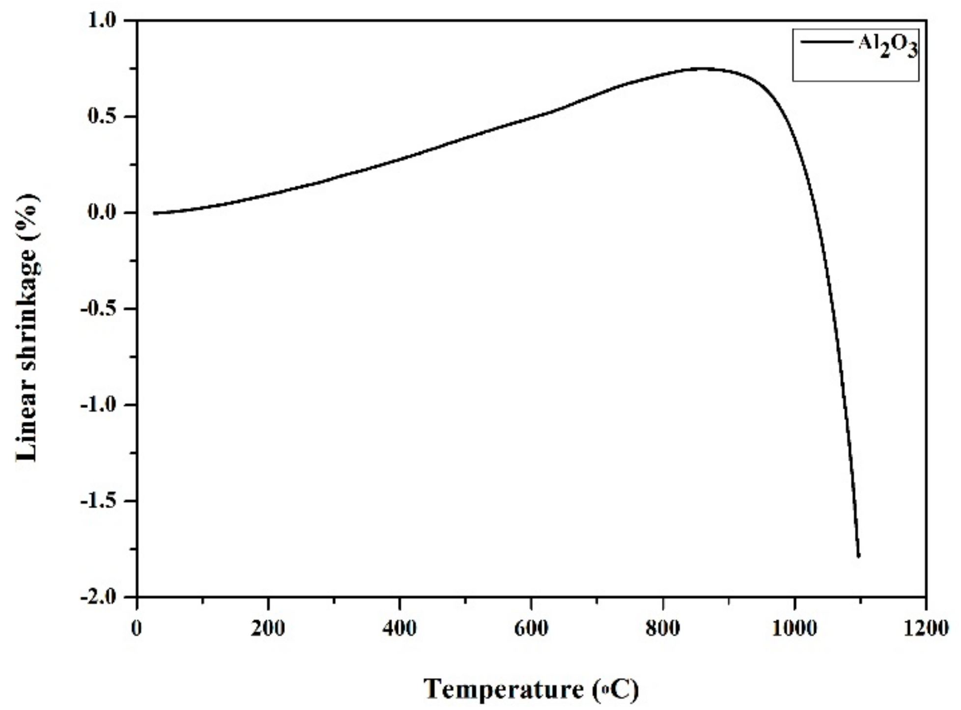
The un-sintered nano-sized Al2O3 powder (α-Al2O3, >99.99%; average particle size, 100 nm; Taimei Chemicals Co., Ltd., Tokyo, Japan) was dry pressed under cold isostatic pressure by means of an Microelectronics Technology Inc. (MTI) laboratory cold press (MTI KJ group, YLJ-24T, Shenyang, China), in stainless steel dies to produce compact tablets (2 mm height and 8 mm diameter) under 200 MPa. To confirm partial sintering, thermal analysis of the alumina pellet was performed for one tablet using a thermal mechanical analyzer (Model SETSYS Evolution-24, Setaram, Lyons, France) in a flowing argon atmosphere (50 mL/min). The shrinkage percentage was shown to be 1.79% when the pellet was heat-treated to 1100 °C at a heating rate of 5 °C/min and cooled to the furnace rate (Figure 1).
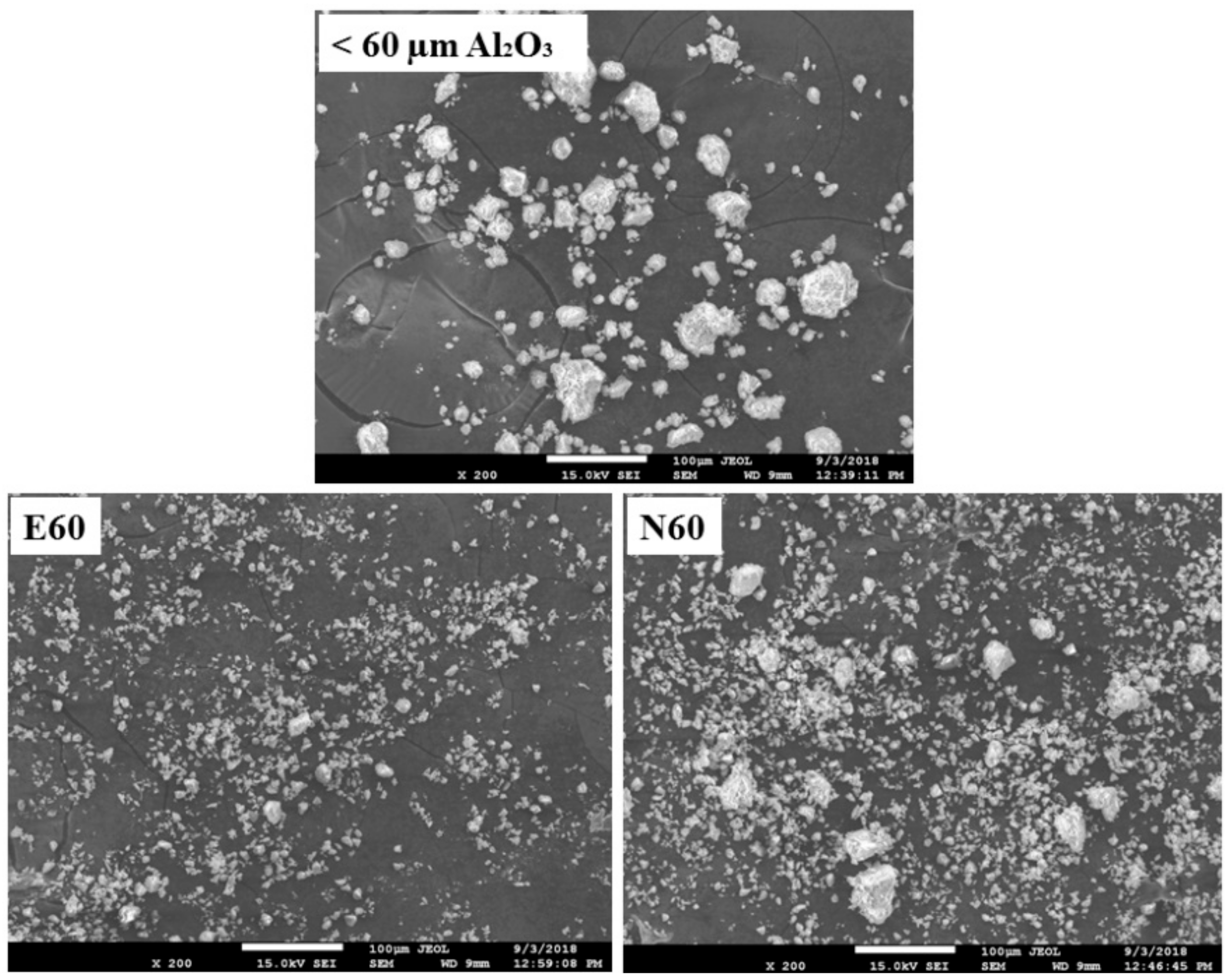
The rest of the pressed alumina specimens were partially sintered in an alumina crucible at 1100 °C for 2 h in a muffle furnace (Xinyu-1400, Nanyang Xinyu New Material Technology Co., Ltd., Nangyang, Henan, China) at a heating rate of 5 °C/min and subsequently cooled to room temperature. A heat treatment schedule was obtained from a previous study [20]. Samples were ground using a silica pestle and mortar. Based on the pilot study, the resulting powder was sieved through a 60 µm mesh (Zhejiang Luda Machinery Instrument Co., Ltd., Shaoxing, Zhejiang, China) to separate powder with a particle size <60 µm. Two sets of composite powder for the coating were prepared and weighed using a precision balance (Sartorius Entris Analytical Balance, Brooklyn, NY, USA). The first powder mixture (composite) consisted of 50 wt % of partially-sintered alumina (<60 µm) and 50 wt % of Ivoclarvivadent Porcelain System (IPS) e.max Ceram glaze. The second powder mixture consisted of 50 wt % of partially-sintered alumina (<60 µm) and 50 wt % Noritake Cerabien ZR glaze porcelain (Figure 2). The selection of the 50 wt % ratio was based on previous studies to avoid the risk of blocking the nozzle of the airbrush spraying system [20,30]. The composite powders were separately dry ball milled at 250 rpm for 15 min in a closed polyethene container with alumina balls of 10 mm diameter, and then subsequently sieved to separate the alumina balls.
2.3. Specimen Grouping according to Surface Modification
A total of 80 pre-sintered zirconia cubes were randomly assigned into four experimental groups (each group n = 20) and subdivided according to the surface treatments applied (airbrush spraying or fine-brush painting by manual deposition) as shown in Table 1.
The chemical components and manufacturers of the selected materials are summarized in Table 2 according to the manufacturer’s data.
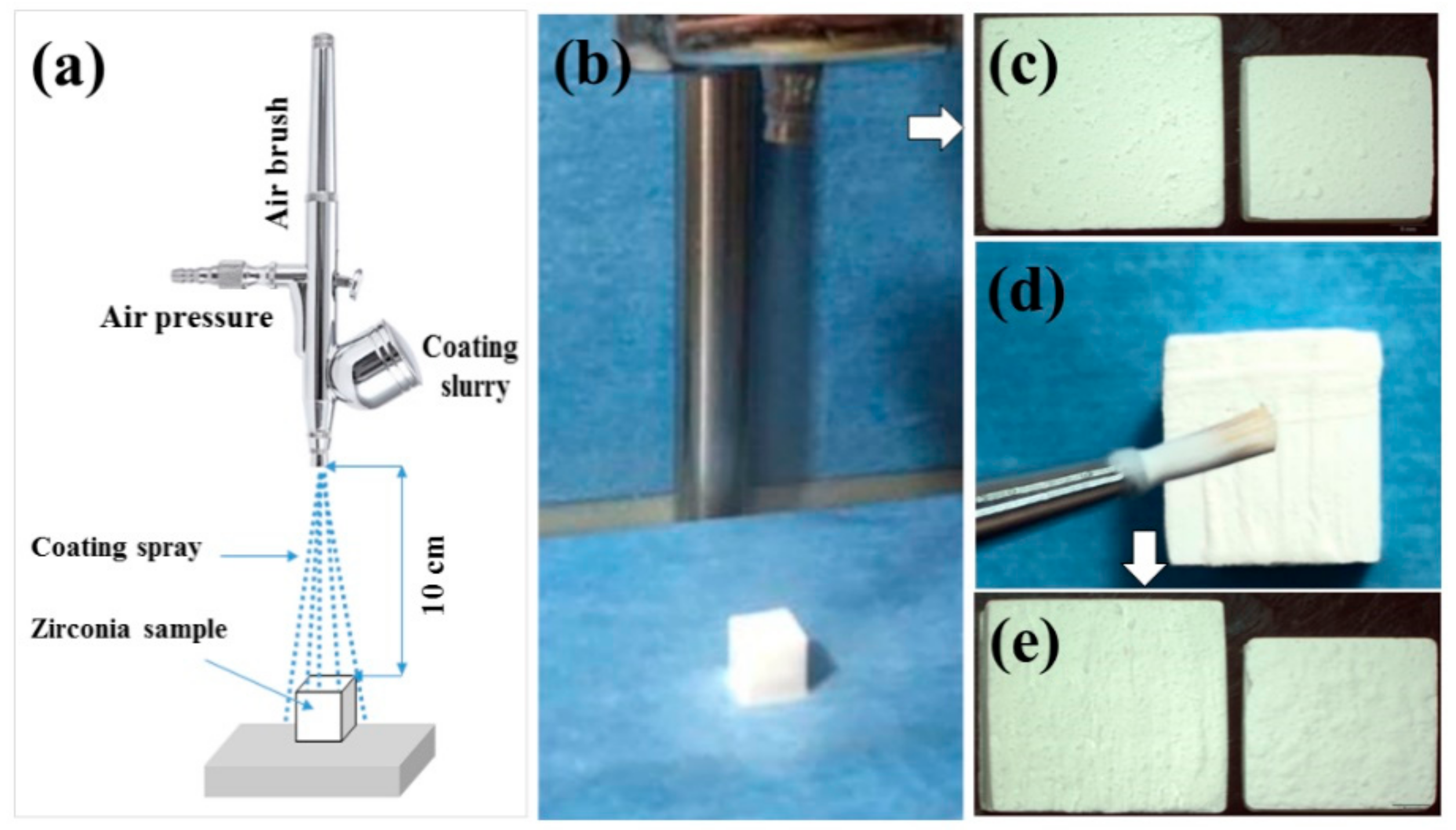
In the airbrush spraying surface treatment, including G1 (E60S) and G3 (N60S), the slurry comprised of mixed alumina powder diluted with 1.5 ml of pure ethanol (≥99.7%) for each of the 40 specimens (20 specimens in each group). The slurry was mixed using a magnetic stirrer (Biobase Meihua Trading Co., Ltd., Jinan, China) at 500 rpm for 15 min to ensure homogeneity of the mixture. The coating spray was applied to one surface of each zirconia specimen, using a mini airbrush spray gun (Model 130-dual action airbrush kit, Bartsharp Airbrush, Taiwan) fixed vertically to the prepared un-sintered zirconia cube by a clamp holder, yielding a spray-dried powder (Figure 3a–c).
The samples were placed on a flat surface during the spraying process to achieve a unique layer of the coating on the core material. The standard quantity and quality of the spraying slurry were preserved by maintaining 2.5 bars of air pressure and 10 s spray time with 10 cm distance between the zirconia cube and airbrush nozzle with a lumen diameter of 0.3 mm. These parameters were applied on the basis of previous studies [20,30]. The coating parameters are summarized in Table 3.
In the fine-brush coating surface treatment, including G2 (E60P) and G4 (N60P), 40 pre-sintered zirconia cubes (20 specimens in each group) were coated with the mixture which was prepared by mixing 55 wt % of alumina composite powders with the corresponding glaze liquid of IPS e.max Ceram and Noritake Cerabine ZR, respectively. The slurry was applied twice [27] to the prepared pre-sintered zirconia cube specimens using a thin brush (Glaze brush (0) KYC series 2700, Shenzhen, China). After the first layer of coating, the specimens were rotated 90° clockwise to apply the second layer and fill the uncoated areas. The time interval between the two layers was 2 s (Figure 3d,e). All eighty surface coated specimens were then fully sintered at 1530 °C for 6 h in the firing furnace of the supplier (Austromat® baSicDekema, Dental Keramiköfen GmbH, Freilassing, Germany) according to a cycle recommended by the furnace manufacturer. The size of each cube following sintering was 10 mm × 10 mm × 10 mm. Then, all specimens were ultrasonically cleaned using a digital ultrasonic cleaner (Jeken, PS-20A, Shenzhen, China) in pure ethanol (≥99.7%) for 10 min, steam cleaned (Dental Steam Cleaner, Nurodent Model S-501, Guangzhou, China) for 10 s, and air dried with compressed air at room temperature.
2.4. Scanning Electron Microscopy (SEM) and Energy Dispersive Spectroscopy (EDS)
SEM (Ultra Plus, ZEISS, Oberkochen, Germany) operating at accelerating voltages of 15 kV was carried out to evaluate the surface morphology of the coated zirconia specimens with different methods. For the observation of the coating quality, morphology, and profile of all specimens, the surface-treated zirconia cubes were cut using a diamond blade under water cooling (MTI KJ group, SYJ-150 low-speed Diamond Saw, Shenyang, China). The specimens were subsequently cleaned with pure ethanol in an ultrasonic bath for 5 min and air dried at room temperature. In each group, two additional zirconia samples were prepared for the top and interface examination. The top surface of specimens, cross-sectional profile, and fractured surface of VC after SBS testing were attached to double-sided conductive carbon tape and sputtered with a thin layer of gold alloy using a sputter coater machine (JS-1600, Beijing HTCY Co., Ltd., Beijing, China) and imaged in a high-resolution SEM at different magnifications for microstructural analyses. The EDS analysis, which is equipped with SEM, was performed to reveal the elemental composition and the influence of the different chemical compositions of the materials used (glazes, VCs, and coated zirconia surfaces).
2.5. Phase Analysis by X-ray Diffraction (XRD)
One coated specimen from each experimental group was randomly selected, then cleaned with pure ethanol in an ultrasonic bath and air dried at room temperature. Phase analysis of the partially sintered powder of alumina and specimens were accomplished using a Smart Lab X-ray diffractometer (Smartlab, Rigaku, Tokyo, Japan) with Cu Kα radiation (λ) of 1.5406 Å, and an accelerating voltage of 40 kV in the 2θ range of 10–90° using a step-scanning technique with a fixed step size of 0.02° at a rate of 10°/min. Data were analyzed using the Origin Pro 8.5 program (OriginLab Corporation, v9.0, Northampton, MA, USA), together with the search and match software Materials Data Inc.(MDI) Jade 6 program (Materials Data Inc., Jada XRD pattern processing, Livermore, CA, USA), to identify the phase following surface treatment. The pattern was plotted by a set of line positions 2θ (°) against the intensity (arbitrary units).
2.6. Ra Evaluation
After surface modification, ten specimens from each group were randomly selected to measure Ra values. The Ra in the micrometer (µm) of the top surface of the study groups were analyzed with a profilometer (Surtronic 25, Taylor Hobson Ltd., Leicester, UK). The Ra, which stands for arithmetical mean roughness, was then determined as the indication of surface roughness of the substructure. A higher Ra value indicated optimum surface roughness [31]. For each new specimen, a calibration was conducted for a standard sample (6.00 µm) which was provided by the manufacturer. Filtering of the measured data at the cut-off (λc) length (0.03 inch = 0.8 mm) was then determined according to recommended ISO 4288-1996 [32]. The test was performed on a flat surface. For each sample, three readings of measured roughness were recorded, and the average Ra was then calculated [18].
2.7. Veneering Procedure
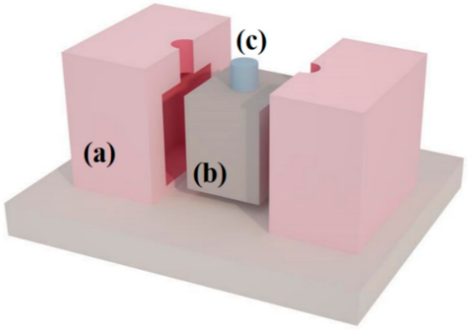
All eighty surface treated specimens were ultrasonically cleaned in ethanol for 10 min and air-dried at room temperature. A specially-designed separable dimensionally-stable custom-made silicon mold (Zhermack S.P.A, Badia Polesine (RO), Italy) was used as a key to layer the VC on the coated face of each cube, covering an area of 3 mm diameter and 5 mm height at the center of the cube face (Figure 4).
The VC cylinders were fabricated using the same layering technique to create 3 mm diameter and 5 mm height specimens [33]. The silicon mold was isolated with the separating medium (Ceramic Separating Stick, Ivoclar Vivadent, Schaan, Liechtenstein, Germany) to avoid the adhesion of VC around the pre-fabricated hole of the silicone mold during layering. Two VCs were utilized including IPS e.max Ceram Type I, Class II Dentine C2/TI3 powder (only dentin) for groups E60S and E60P, and Noritake Cerabien ZR for groups N60S and N60P in the veneering procedure. The IPS e.max Ceram was mixed with an appropriate amount of the respective liquid according to common practice in the dental laboratory and filled into the mold. With gentle vibration, excess liquid was removed with a tissue, and a uniform cylinder was ensured in the layers to prevent air bubble trapping. In each combination, 40 specimens were veneered to E60S (n = 20) and E60P (n = 20) groups. An identical procedure was performed for veneering N60S (n = 20) and N60P (n = 20) groups with Noritake Cerabien ZR VC. The coated zirconia specimens with VC were fired into full density in a programmable and calibrated ceramic oven (Programat P300, Ivoclar Vivadent, Liechtenstein, Germany) according to suggested firing schedule by the manufacturer for each VC (Table 4). The percentage of shrinkage after sintering was 10% for IPS e.max Ceram and 20% Noritake Cerabine ZR, respectively according to manufacture information [34].
To compensate for the shrinkage of sintering under the same conditions, a second firing was carried out to achieve a final veneering of 3 mm diameter and 5 mm height. After firing, the specimens were cooled to air atmosphere. Excess VC was removed with a dental laboratory engine (N3 Micromotor Polishing Unit, Beijing, China) with a low-speed carbide hand piece (HP) fissure bur (Busch and Co., Ltd., Engelskirchen, Germany), which was gently applied with minimal pressure to yield the correct final dimensions of VCs and clear the interface without a damaging effect on the interface. All the specimens were then kept at room temperature for 24 h before the further processing.
2.8. Shear Bond Strength (SBS) Test
For performing SBS testing, ten specimens in each group were evaluated for the initial SBS (not stored in deionized water (DW) without aging), and the other half of the specimens in each group were evaluated after being stored in DW at 37 °C for one month (aging). At pre-determined times, specimens were thoroughly rinsed and air-dried at room temperature. Specimens were individually mounted in a special sample holder before being loaded in a universal testing machine (Shimadzu, AG-X plus, Tokyo, Japan). A testing load was applied perpendicular to the long axis of the specimen and close to the interface using a semicircular shaped piston (Figure 5) at a constant crosshead speed of 1 mm/min until specimen fracture as recommended by the International Standards Organization (ISO) [35]. The SBS test in MPa was calculated by the corresponding software (Trapezium X, Version 1.4.0, Shimdazu Corporation, Tokyo, Japan) by dividing the ultimate load to failure in Newton (N) by the area of the bonded surface (mm2). The recorded load was calculated using the formula b = f/s, where b, f, and s denote the bonding, force, and surface area, respectively.
2.9. Fracture Pattern Examination
The coated surface of each experimental group before and after sintering (Figure 3c,e) and the pattern of failure following SBS testing were visually examined under a stereomicroscope (Olympus SZ61, Shanghai, China) at 20× magnification and further investigated with SEM. The failure modes were classified as follows:
- Adhesive failure modes at the core-VC interface;
- Cohesive failure within the VC;
- Mixed mode of failure combination of the adhesive and cohesive modes.
The fracture mode patterns for each tested group were recorded regarding percentages.
2.10. Statistical Analysis
The final results were statistically analyzed using the IBM Statistical Package for Social Sciences software (SPSS 20.0, IBM®SPSS®Inc., Chicago, IL, USA).
The Kolmogorov–Smirnov normality test was applied for checking the distribution of Ra and for SBS values, and the Levene statistic test was used to test the homogeneity (equality) of variances.
The results of normal and non-normal distributed variables were tested with a one-way ANOVA test with the multiple comparisons post hoc test and Kruskal–Wallis H test in conjunction with unpaired Mann-Whitney U test, respectively. A parametric paired t-test was performed to compare the means of SBS values of specimens before and after storage in water in normally distributed groups and non-parametric paired Wilcoxon test for non-normally distributed groups.
The general linear model (univariate) was used to test the effect of treatment methods (airbrush spraying and fine-brush painting), and coating materials to find the outcomes between-subjects effects for two factors, with Ra as the dependent variable. The general linear model was also used to test the effect of treatment methods, coating materials and aging to find the outcomes between-subjects effects for two and three factors, with SBS as the dependent variable.
The Spearman correlation coefficient test was used to find a correlation between Ra and SBS. The thickness of the coating at the interface level in µm was measured in four different areas with the SMile View™ software (SMile View™ version 2.1, JEOL Ltd., Tokyo, Japan). The significance level was calculated at α = 0.05.
3. Results
3.1. Coating Formation
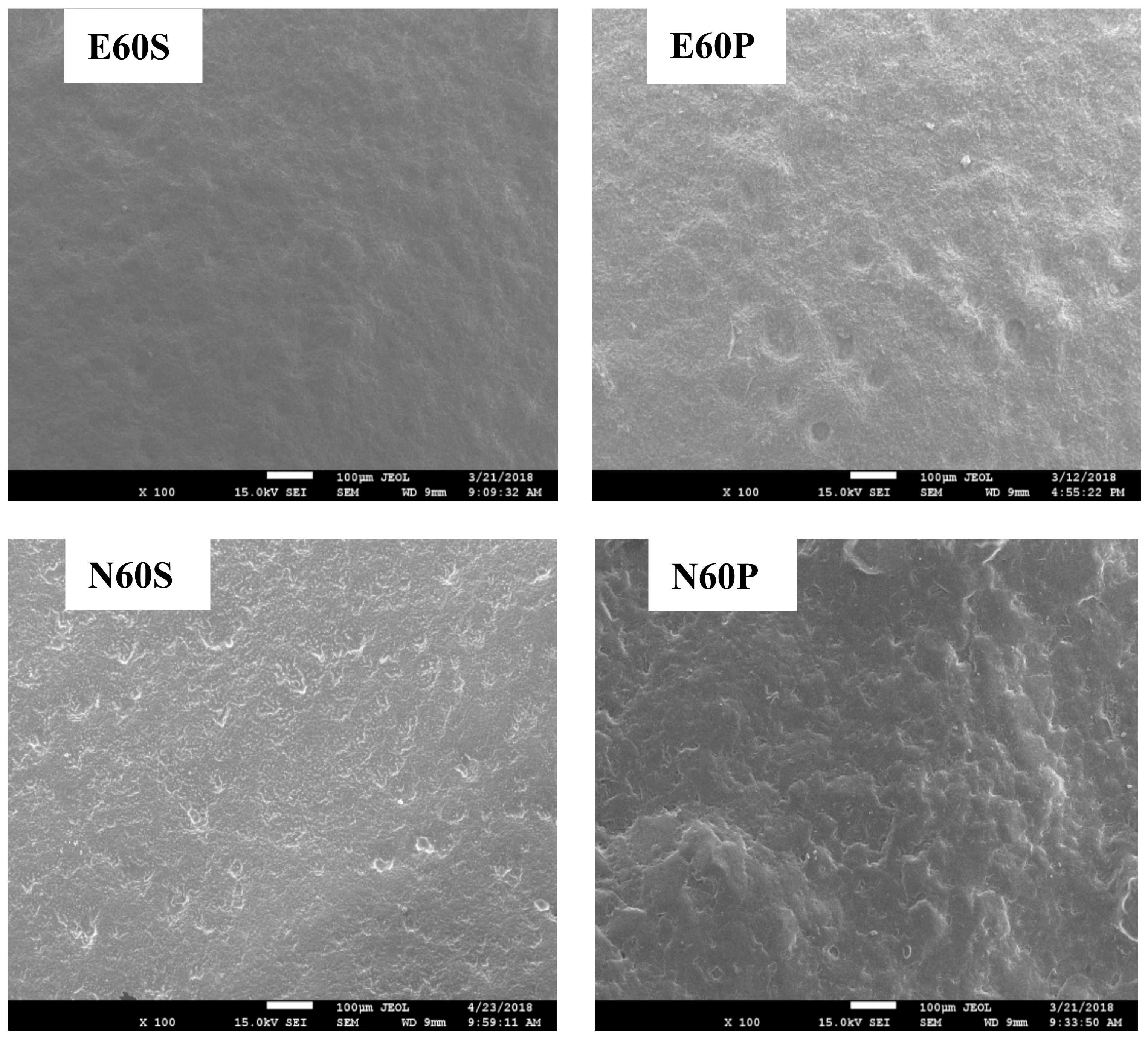
Airbrush spraying deposition and fine-brush coating of zirconia in the four groups successfully formed a layer of alumina and glass when fired using zirconia-heating schedules without evidence of chipping or delamination. Representative SEM images of surface changes in the zirconia surfaces after airbrush spraying and fine-brush painting are presented in Figure 6. Differences in the specimen surface irregularities were verified by SEM imaging. In the airbrush deposition groups (E60S and N60S), micro-sized irregularities can be distinguished on the zirconia surfaces, which were relatively smooth. In the fine-brush painting groups (E60P and N60P), many irregularities were detected on the surfaces, which were relatively rough.
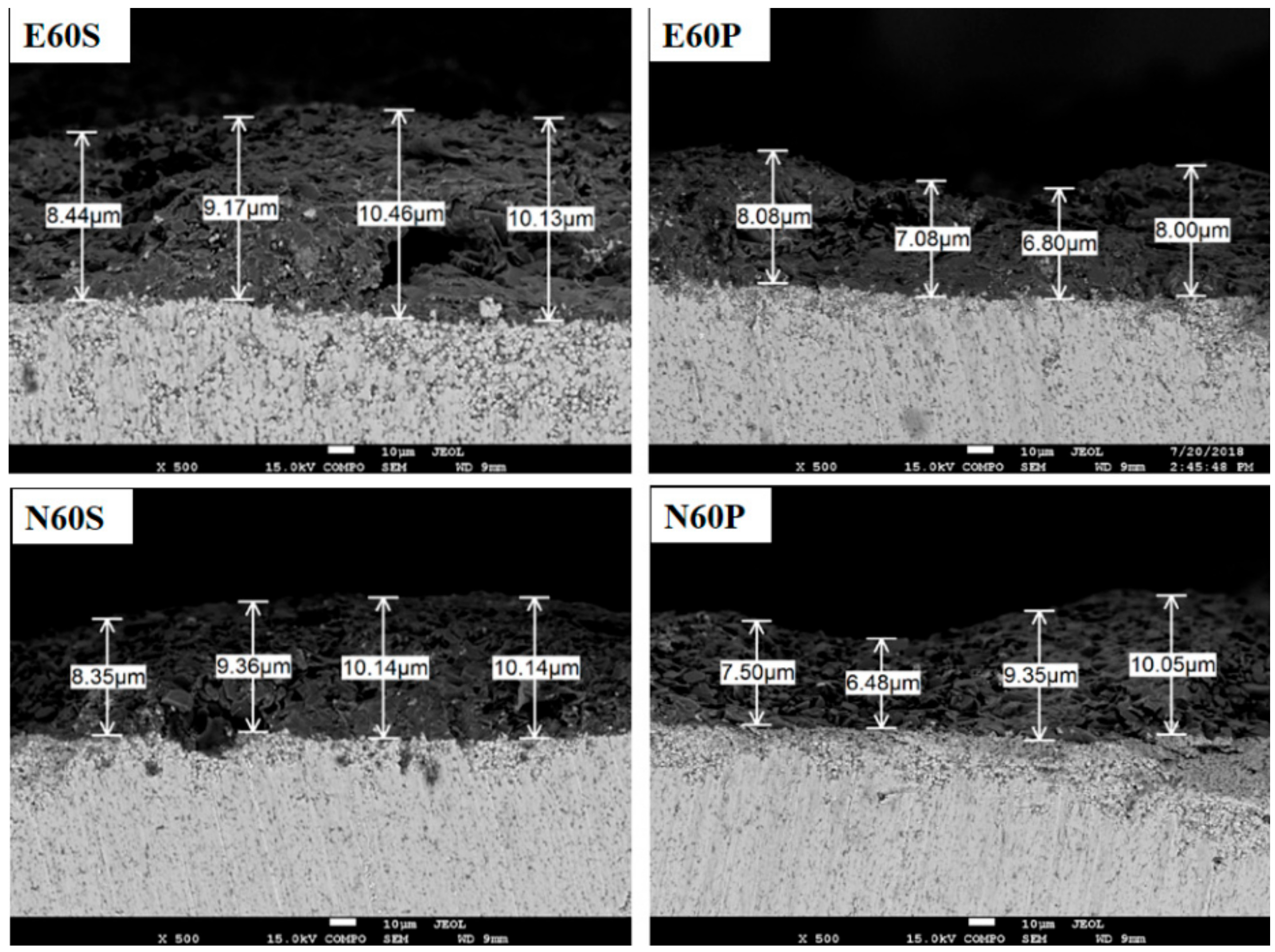
Continuous coatings along the cross-sectional profile of the zirconia substrate were obtained in all groups, thereby indicating complete adhesion between the core and coating (Figure 7). The surface of the coating appeared to be a more homogenous layer formed on the airbrush spraying groups compared to the well-prominent rough and prominent irregularities with evident depression areas, which were visible in the fine-brush treated surfaces. The measured average cross-sectional coating thickness was 9.523 ± 0.820 µm for airbrush spraying groups, and 7.917 ± 1.243 µm for fine-brush deposited groups.
3.2. XRD
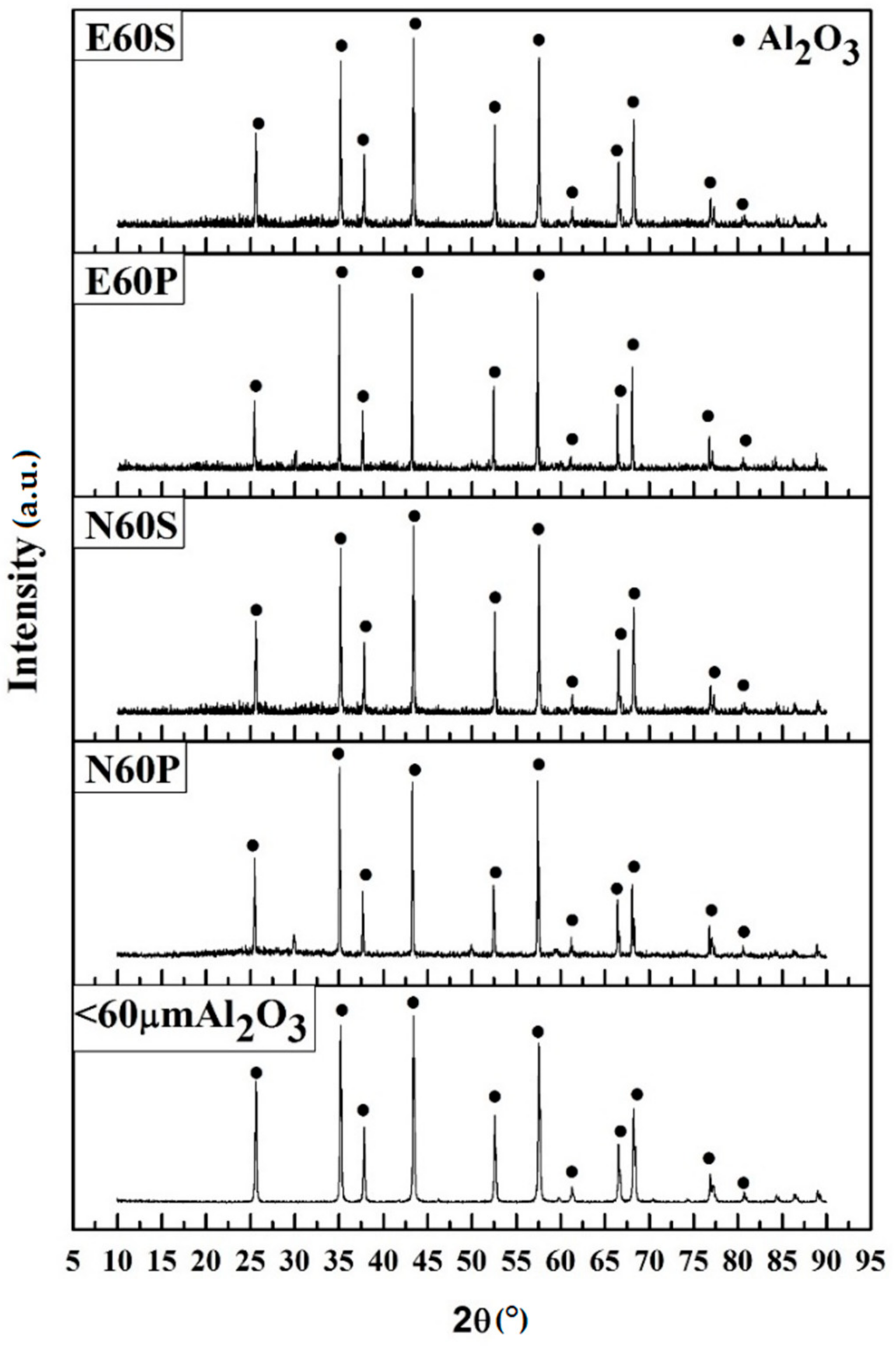
The XRD patterns for alumina with a particle size of <60 µm and study groups are presented in Figure 8. The sample of alumina powder (<60 µm) that was subjected to 1100 °C revealed an alumina crystalline phase (α-Al2O3), as predicted from the XRD standard PDF file (PDF 81-1667). However, at a higher temperature, some differences were observed following various surface treatments of the experimental groups. The heat treatment at 1530 °C resulted in crystallized α-Al2O3 with sharp XRD peaks, while the glazes subjected to the same temperature possessed small XRD peaks and matched with the standard PDF file (PDF 81-1667). The phase of zirconia was undetected in the XRD patterns, which indicated that the coating processes modified the zirconia surface.
3.3. Ra
The normality test revealed a non-normal distribution of Ra among groups (p < 0.001). However, the Levene statistic test showed a homogeneity of variances between groups (Levene = 0.790, p > 0.05). Table 5 demonstrates the outcomes of the mean and SD of Ra of the study groups. The results of the mean value (±SD) of Ra were 1.154 (±0.160) μm for E60S, while in the E60P group, it had increased to 3.177 (±0.204) μm. In group N60S, it was 1.395 (±0.243) μm, and for N60P, it had increased to 5.717 (±0.206) μm. The non-parametric Kruskal–Wallis test showed a significant difference in Ra (p < 0.001). The unpaired Mann-Whitney U test showed the difference between every two groups was significant at the 0.001 level and the 0.05 level between E60S and N60S, respectively. General linear model analysis revealed that the treatment technique, coating materials and their interaction were statistically significant (p < 0.001), thereby indicating that the Ra value was significantly affected by the technique and coating materials used (Table 6).
3.4. SBS
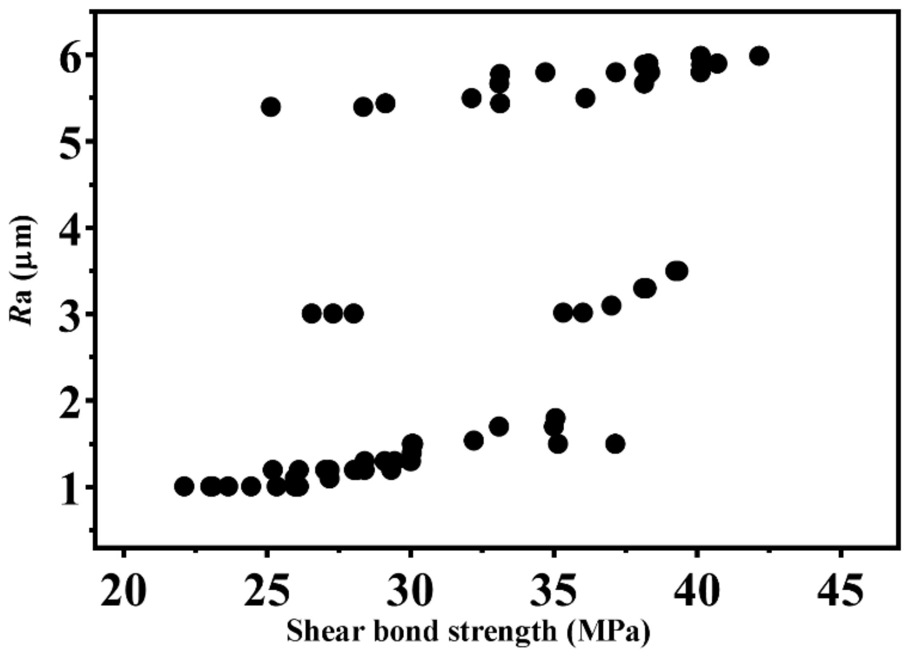
The normality test showed that there was non-normal SBS distribution before water storage between groups (p < 0.05), and normal SBS distribution after water storage (p > 0.05). However, the Levene statistic test showed that there was homogeneity of variances among groups in the initial SBS (Levene = 1.301, p > 0.05) and after water storage (Levene = 0.698, p > 0.05). Table 7 and Table 8 present the SBS values of the different surface treatment groups. In Table 7, the Kruskal–Wallis non-parametric test showed that a significant difference in the initial SBS was found among groups (p < 0.001). The lowest initial mean shear bond strength was obtained in the E60S group (27.93 ± 3.096 MPa) which was significantly lower than E60P (p < 0.01), N60S (p < 0.05) and N60P (p < 0.01). The highest initial SBS was found in N60P (37.22 ± 4.954 MPa), which was significantly higher than the E60S and N60S groups (p < 0.01). However, the differences between the E60P and N60S groups and between E60P and N60P were not significant (p < 0.05). The spontaneous detachment of the coating or VCs from zirconia was not observed following 30 days of water storage. After water storage for one month, the bond strength of all groups was observed to decrease. One-way ANOVA revealed a significant difference in SBS among groups (F = 6.539, p < 0.01). The N60P group still exhibited the highest mean strength of 34.42 ± 3.977 MPa, and the E60S group had the lowest mean strength of 26.83 ± 3.984 MPa. After adjusting for multiple comparison analysis, the differences among E60S, E60P, and N60S groups were not significant (p > 0.05). However, the N60P group was found to be significantly higher than the E60S and N60S groups at the 0.01 level. There was no significant difference between identical procedures found in water storage conditions. However, in each group, the initial mean SBS value was significantly different from that after storage in water conditions except the N60S group. Spearman’s correlation test showed a statistically significant correlation between Ra and SBS (Spearman rho = 0.808, p < 0.001), as shown in Figure 9.
The general linear model analyzed that the effect of treatment methods and coating materials was statistically significant at the 0.001 level on SBS (Table 9). However, the effect of aging and the interactions were not statistically significant (p > 0.05) on the SBS.
3.5. Mode of Failure
The outcome of the fracture mode patterns of the specimens initially and following water storage on SBS was recorded in percentages (Table 9). The highest percentage of adhesive fracture mode was recorded in the E60S and N60S groups, and the cohesive mode of failure was absent regardless of the aging treatment. The result indicated a relatively weak adhesion on the zirconia/VC interface. The predominant mode of failure in N60P and E60P groups was cohesive and mixed in the initial and aging conditions, respectively. The mixed mode of failure can be distinguished in all groups with varying percentages.
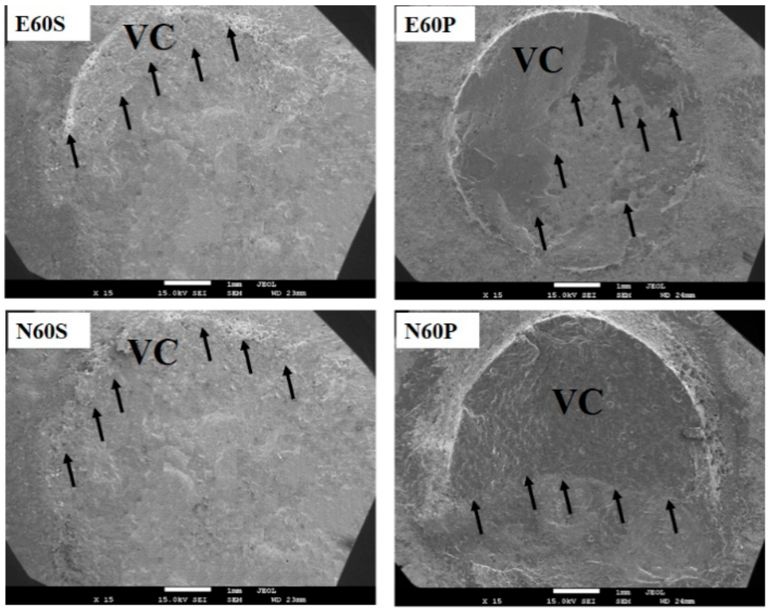
SEM images confirmed different failure mode patterns such as adhesive, cohesive and mixed modes of failure after performing the SBS test (Figure 10). The SEM image of de-bonded samples revealed a circular pattern with a clear, distinct, and circular boundary, thereby suggesting that shearing left a thin circular layer of veneering material attached to the coated zirconia core in the airbrush sprayed groups, which corresponded to the adhesive mode of failure. Nonetheless, failure primarily occurred in the veneer part, and the residual VC covering the core surface revealed that the veneering material remained on the core surface after de-bonding and adhered to the core in the fine- brush treated groups. Irregular fracture lines were initiated on the core/veneer interface and propagated along the zirconia/VC interface, thereby representing the mixed (E60P group) and cohesive modes (N60P group) of failure.
3.6. Surface Elemental Composition Analysis
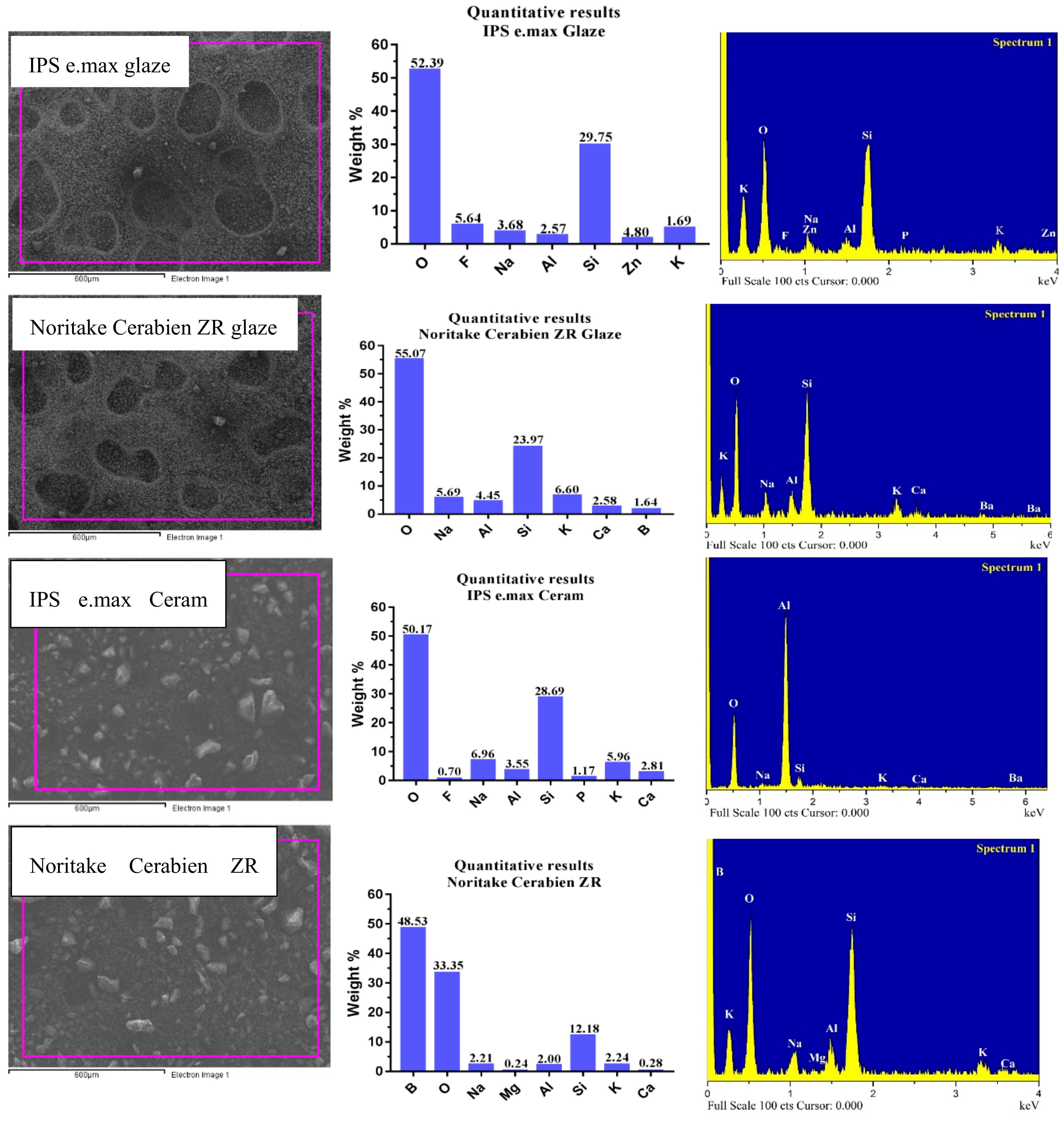
EDS analysis confirmed that the chemical components of IPS e.max Ceram glaze, Noritake Cerabien ZR glaze powder, IPS e.max Ceram and Noritake Cerabien ZR VCs were the same as those claimed by the manufacturer except for the element Li, which was not found in the Noritake Cerabien ZR ceramic as shown in Figure 11.
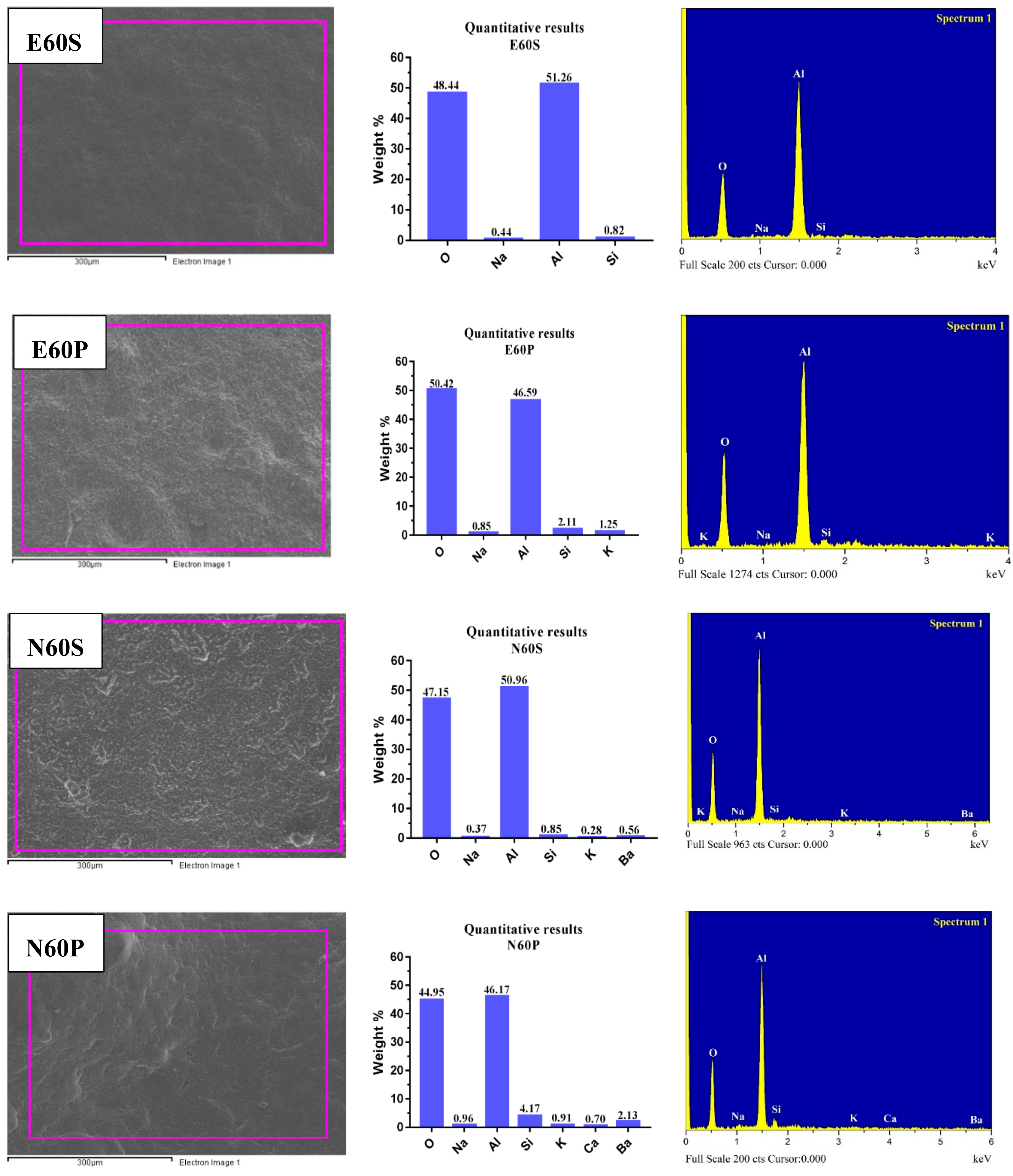
The EDS results of the zirconia surface modified with various techniques are demonstrated in Figure 12. All IPS e.max glaze compositions were detected except for Zn. K elements in the E60S group and Zn elements in the E60P group were invalid. Ca elements were nonexistent in the N60S group, whereas the elemental constitution of N60P was similar to that of Noritake Cerabien ZR glaze. There was more alumina detected over the surface of the airbrush spraying than fine-brush painting groups. However, more Si elements were observed in the latter group, which is essential for chemical bonding.
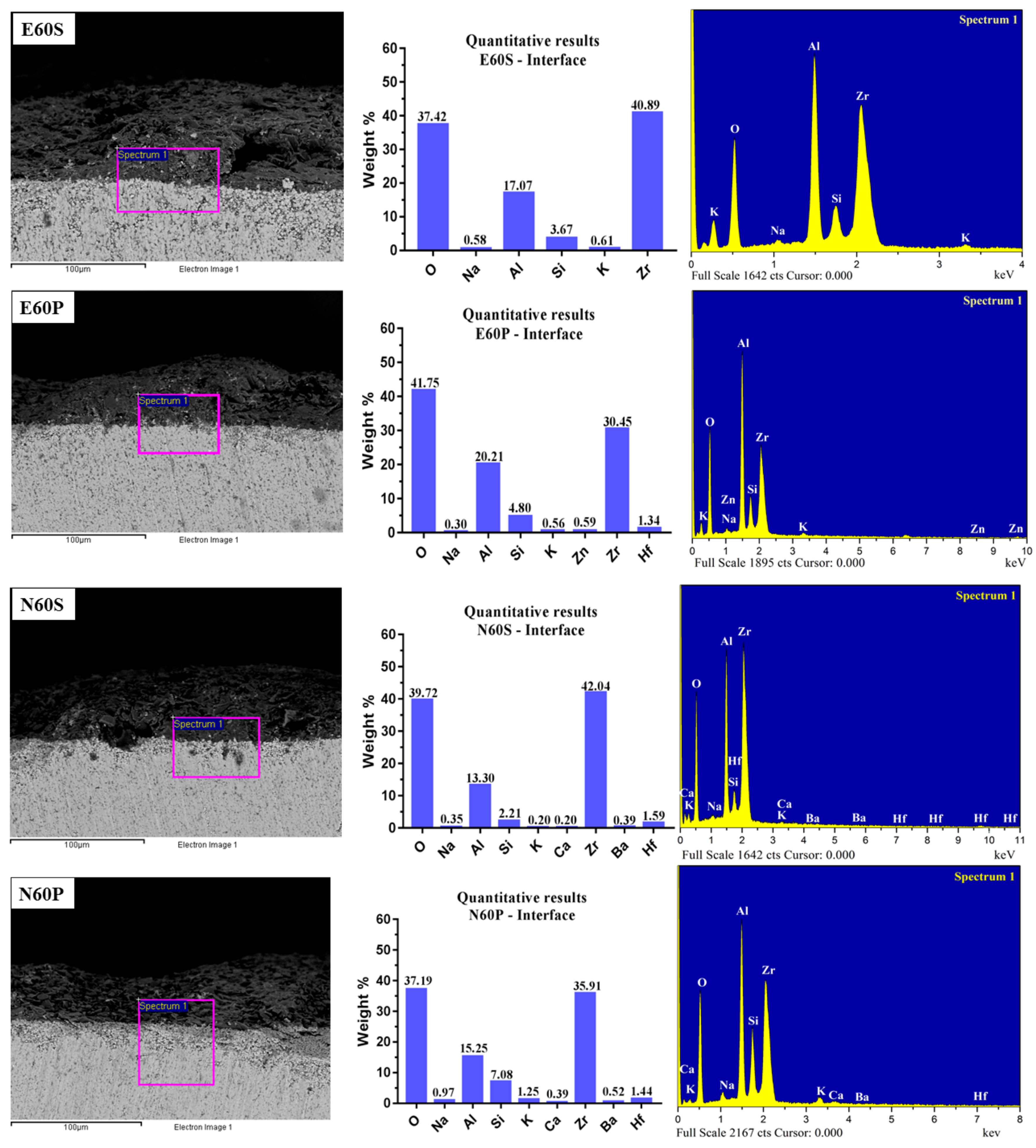
EDS analysis showed that substantial oxygen, alumina, silicon, and zirconia elements (at the interface) were detected in all groups. These results revealed that the coating mixture components did not disappear or change after full zirconia sintering, as can be seen in Figure 13.
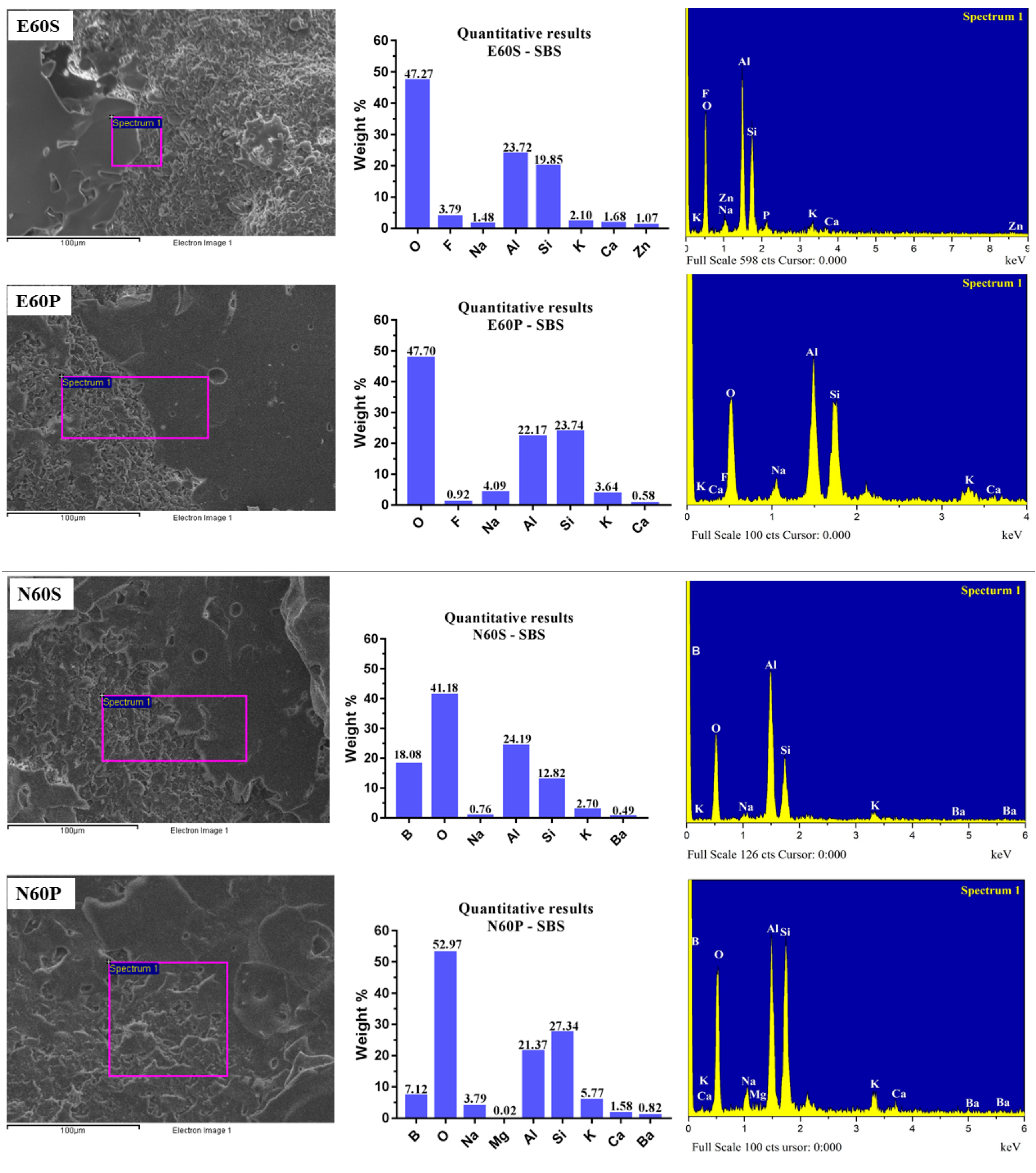
The EDS results for interface areas after SBS testing of different surface treatments are presented in Figure 14. These results indicated the silicon element is considered as the main element in the glaze and VC. A large amount of silicon element remained on the surface of E60P and N60P compared to the E60S and N60S groups.
4. Discussion
Previous studies have reported that the application of a glaze or low fusion porcelain on the zirconia core prior to VC promoted zirconia–porcelain bond strength [8,36]. However, the zirconia/glazed interface layer has been shown to provide a relatively weak bond, and delamination related to a mismatch in their CTE can occur [36]. The rationale for using alumina (<60 µm) was based on optimizing a rough surface to enhance micromechanical retention, and combining with a glaze as a mediator increases the wetting property [13] and improves the chemical adhesion on the zirconia surface between coating and zirconia specimens and VC [20]. On such bases, alumina composite coatings on surface modification of the inert surfaces of high strength zirconia ceramics has been proposed in this study. Alumina is a suitable candidate for zirconia surface modification due to its high strength, toughness and excellent biocompatibility [22]. XRD, SEM and EDS evaluations demonstrated that the deposition of composite crystal alumina (<60 µm) and glaze porcelain successfully modified the zirconia surface using different strategies at a high sintering temperature (1530 °C). Non-invasive alumina composite treatment on zirconia surfaces can survive thermal cycling [25]. Alumina is one of the most important ceramic materials, as it has relatively high melting (2054 °C) and boiling temperatures (2980 °C), ultra-high thermal stability and mechanical strength [37]. The XRD trace revealed that partially-sintered alumina (<60 µm) resulted in the formation of a purely alpha alumina crystalline phase. When subjected to a higher temperature with different glazes as a coating on the zirconia surface, a composite alpha alumina crystalline phase and glass were formed, and alumina peaks were dominant as the major crystalline phase instead of zirconia. The sharp peak intensities indicate high crystallinity and small peaks referred to the glass content.
The high-strength and fracture toughness of zirconia support its extensive application in aesthetic dentistry [27]. However, VC delamination from the core structure is frequently observed in the clinical situation [20], and its fracture remains a primary cause of failure [14,27]. Therefore, in achieving acceptable VC bonding in a wide range of clinical applications, alternative treatment methods that ideally utilize chemical adhesion in addition to mechanical retention [38] are required for zirconia ceramics.
The choice of non-destructive methods, such as airbrush spraying [20] and fine-brush deposition [27] are desirable for surface modification of inert zirconia ceramics to produce functionalized surfaces. A continuous composite coating with some degree of porosity for E60S and N60S with a constant thickness and minor irregularities was formed with zirconia substrate using airbrush spraying. Many variables, such as spraying air pressure, nozzle diameter, mixture dilution, the distance of the airbrush nozzle to the substrate, and the total spray time can affect the production of a homogenous and uniform thickness of deposited layers [20,30]. In this study, these parameters were selected and kept constant on the basis of the previous study to achieve the desirable coating thickness [20].
A successful surface adhesion was also obtained using fine-brush painting between zirconia and coating layers in E60P and N60P without evidence of cracking, spacing, or delamination at the interface when the composite was blended with the glaze liquid. The previous investigation applied this method with un-sintered zirconia powder mixed with glue (GF-8023) to modify the zirconia surface [27]. The thickness of the airbrush spraying groups represented a slightly higher value than the fine-brush painting groups. This phenomenon can be explained by the presence of irregularities in the latter group, and the thickness is dependent on the number of spraying cycles when airbrush spraying is used [30].
The surface coating is the additive approach for increasing the Ra of zirconia. In this study, it was also observed that the Ra promotion, which was caused by both procedures, resulted in the remodeling of zirconia surfaces. The values of the zirconia Ra were claimed to be significantly promoted after being airbrush sprayed with two different particle sizes—26.0 ± 0.3 µm and 47.0 ± 0.5 µm of pre-sintered zirconia [20]—and recorded higher Ra values than the current investigation. In this study, the particle size of alumina (<60 µm) was kept constant. Discrepancies in the results between the previous investigation [20] and the current study may be due to the use of various particle sizes and coating materials. Varying the glass percentage by weight may influence the melting temperature and its effectiveness in infiltrating the zirconia surface [39]. However, in the present study, results revealed a significant improvement in the average Ra of the fine-brush treated groups when compared to the alcoholic vapor deposition groups, particularly in N60P (Table 5). This finding is consistent with the previously reported literature [27]. This phenomenon can be explained by the different application mode (treatment) and coating materials (Table 6). The Ra in the airbrush spraying groups were the lower than their counterpart groups, and they also showed the lowest resistance to aging conditions. The current findings highlighted a potential influence of the application process (treatment technique) on Ra behavior of the treated zirconia ceramic, which denied the first hypothesis.
The enhancement of bonding between zirconia and VC is a prerequisite for improving clinical success and longevity of prosthetic restorations [6]. Clinical failures of zirconia FPDs often occur due to fractures or chipping of the VC, and this problem must be solved to obtain greater adhesion [6].
In the present study, the adhesion of two different VCs to surface-modified zirconia cores with different surface treatment processes was determined using the SBS test. SBS tests or microtensile tests are generally used to evaluate the bond strength of bi-layered zirconia-based ceramic systems [13]. The SBS test was used in this study because of its simplicity compared with other test methods, the ease of specimen preparation, applied forces perpendicular to the bonding zone, and the test reading was unaffected by inner structural flaws, which may be formed by the small cross-sectional area of the bonded surface to test the material [20,40]. The rationale for one-month water storage was based on observation of the longevity of the bond stability between the zirconia core and coating and the coating and VC. It was found in our study that after being subjected to the aging treatment, the bond strength is still higher in fine-brush painting than airbrush spraying. It has been observed that all aged specimens could survive the wet condition without evidence of chipping and delamination in either coating or spontaneous detachment of VC materials in one-month aging by storage in DW. Increased Ra in turn resulted in increased surface energy and better wetting for bonding [41]. The positive effect of stability in zirconia/coating and coating/VC integration needs to be invested further in long-term water storage.
The previous study reported that the mean (SD) SBS value was 47.02 ± 6.4 MPa for fine-brush painted 3 µm un-sintered zirconia on a zirconia core surface in dry conditions [27]. In this study, the initial SBS values of fine-brush painting of E60P and N60P were 34.51 ± 5.152 MPa and 37.22 ± 4.954 MPa, respectively. The discrepancy in the values of SBS with the current study can be attributed to factors such as coating materials, the use of different VC (Cercon Ceram), heating schedules for VC, and the specimen design. The results indicated a variation in the coating process, and materials involved in the VC adhesion—a rough surface resulted in high SBS. The irregularities in the core surface and the increased contact area with the VC improved the mechanical retention and the SBS values, thereby reducing the possibility of delamination [9]. The fine-brush painting groups showed the highest mean value of SBS of VC in initial and aged conditions (Table 7), which implied that these irregularities created a rougher surface and increased the contact area with the veneering material compared to those in the other coated groups, which is supported by the SEM and Ra values. These irregularities may act as the mechanical retentive means, which strengthened the integration between VC and the zirconia substructure [20]. The results are in accordance with the previous study that such treatment significantly enhanced Ra and SBS between zirconia and the VC [27].
The relatively low SBS measured after airbrush spraying compared with those generated by the manual deposition approach in dry and wet conditions could also support this claim. The SBS values in a dry condition in the present study in the airbrush spraying groups of E60S and N60S were 27.93 ± 3.096 MPa and 29.80 ± 3.799 MPa, respectively. In contrast to our findings, the previous study showed that the zirconia specimens treated with airbrush spraying significantly improved the SBS to the VC (Cercon Ceram Kiss) with cylindrical shape (3 mm height × 3 mm diameter). The coated group revealed the highest value of SBS 37.54 ±4.38 MPa in dry conditions, which had a modified zirconia core surface with 47 µm un-sintered zirconia powder with Cercon Ceram Kiss glaze [20]. The discrepancy in results may be attributed to the same reasons explained earlier. Given that our findings depicted that the fine-brush painting groups presented high SBS, the second tested hypothesis was also rejected.
Both mechanical interlocking and primary chemical bonding have been documented to play a pivotal role in the interfacial adhesion mechanism [42]. The EDS analysis of elements found in the present study confirmed the general components provided by the manufacture (Figure 11) and no major elemental changes in the coating mixture after the sintering process had occurred (Figure 12). During EDS analysis, the carbon element and other automatic selection of elements by the system were removed to eliminate the bias of the procedural section [43]. The differences in interfacial adhesion mechanisms between the interface of the coating/zirconia and coating/VC were that the former adhered to the flat surface and the latter to the rough surface. It has been shown that if the ceramic surface is smooth, the bond is dependent only on the silicon and oxygen and this then becomes a function of the surface composition and chemistry of the ceramic and not its surface topography [43]. In addition, a possible glass infiltration may occur during sintering. Nonetheless, according to the results of airbrush spraying in the current study, it may still be difficult to get a stable coated zirconia/VC adhesion. The EDS analysis showed lower silicon on the airbrush sprayed groups; this compromised the proper chemical bonding (Figure 13). The addition of Si-containing porcelain provides the necessary foundation for the establishment of chemical integration [36].
The presence of some microporosity in the interface level within the airbrush sprayed group might account for these results, in addition to the application process. This treatment did not appear to enhance the micromechanical retention needed for efficient mechanical and chemical bonding between zirconia and VC and the reduced Ra reflected in the reduced SBS values compared to the counterpart treatment.
Failure mode classification was consistent with the previous study using the SBS test [21]. In this study, the fractographic analysis of SBS tested specimens using SEM exhibited different fracture modes for the tested groups. The results of the E60P and N60P groups revealed a higher percentage of the mixed and cohesive mode of failure in both initial and wet storage than the other tested groups. It has been reported that when the surface becomes rougher, the bond strength will increase [13]. The Spearman test confirmed this claim that there is a significant correlation between Ra and the SBS test. A high percentage of the adhesive mode of fracture obtained for both the E60S and N60S groups in dry and wet conditions were due to the lower roughness values.
Interestingly, none of the specimens of the airbrush spraying groups failed cohesively. The results are not consistent with the previously reported literature [20]. The results have been explained by the effect of mechanical and chemical bonding, as has been proven by EDS analysis (Figure 14). Accurate selection of treatment technique and appropriate use of materials will assist in the approach to obtain reliable and durable zirconia/VC bonding.
The fine-brush painting technique can be considered an alternative treatment modality to other surface treatments to zirconia cores to avoid VC delamination and microcrack formation at the intergrain level, which will be detrimental to the longevity of ceramic restoration. This procedure is a highly versatile yet practical approach, which allows for the fabrication of rough bearing thin film coatings that are simple, strong, technique insensitive, and cost-effective material processing techniques. Furthermore, such coatings present the potential for a wide range of applications for the zirconia core with conventional and complex shapes (single crown and bridge) of fixed zirconia ceramic restorations.
The generalizability of these results is subject to certain limitations. For instance, the study did not include a control group because different materials and processes were used. The current study was unable to evaluate the possible negative effects of the CTE mismatch since glass and alumina have distinct CTE to that of zirconia. With the glass infiltrated zirconia, however, possible new crystalline phases formed during sintering could potentially minimize or compromise this aspect. The current in vitro study has only examined 30 days DW storage of the samples, and longer durations or an in vivo study is required to evaluate this approach regarding performance during clinical service. Although in vitro experiments are valid in determining the effects of such variables, randomized clinical studies should be incentivized to provide information about alumina composite coating behavior during service to improve the long-term success of restorations.
5. Conclusions
Within the limitations of the current study, the following conclusions can be drawn. The most striking observation was that the bond strength values of the coated zirconia core to VCs are significantly affected by Ra, treatment, and materials used. The coated specimens with alumina glaze mixture in the N60P group possess the highest SBS yield among the tested groups. The novel coatings by means of fine-brush painting are a promising surface treatment and an easy technique to obtain Ra, which subsequently improves the bond strength to VC.
Author Contributions
Conceptualization, F.K.M., S.P., X.S. and Y.L.; Methodology, F.M.; Software, F.K.M., S.P., X.S., A.O.A. and Y.L.; Supervision, X.S. and Y.L; Writing–Review & Editing, F.M., S.P., S.X., A.O.A. and Y.L.
Funding
This research was funded by the Chinese Scholarship Council (CSC) (No. 2016368012) and Liaoning Provincial Universities and Colleges Co-cultivation Post-graduate Project (No. 115-3110617005).
Acknowledgments
Authors would like to acknowledge Ching Mai dental laboratory for permitting the use of laboratory equipment.
Conflicts of Interest
The authors declare no conflict of interest.
References
- Thompson, J.Y.; Stoner, B.R.; Piascik, J.R.; Smith, R. Adhesion/cementation to zirconia and other non-silicate ceramics: Where are we now? Dent. Mater. 2011, 27, 71–82. [Google Scholar] [CrossRef] [PubMed] [Green Version]
- Denry, I.; Kelly, J.R. State of the art of zirconia for dental applications. Dent. Mater. 2008, 24, 299–307. [Google Scholar] [CrossRef] [PubMed]
- Kelly, J.R.; Denry, I. Stabilized zirconia as a structural ceramic: An overview. Dent. Mater. 2008, 24, 289–298. [Google Scholar] [CrossRef] [PubMed]
- Manicone, P.F.; Rossi, I.P.; Raffaelli, L. An overview of zirconia ceramics: Basic properties and clinical applications. J. Dent. 2007, 35, 819–826. [Google Scholar] [CrossRef] [PubMed]
- Kosmac, T.; Oblak, C.; Jevnikar, P.; Funduk, N.; Marion, L. Strength and reliability of surface treated Y-TZP dental ceramics. J. Biomed. Mater. Res. 2000, 53, 304–313. [Google Scholar] [CrossRef]
- Elsaka, S.E. Influence of surface treatments on the surface properties of different zirconia cores and adhesion of zirconia-veneering ceramic systems. Dent. Mater. 2013, 29, e239–e251. [Google Scholar] [CrossRef] [PubMed]
- Lee, M.H.; Min, B.K.; Son, J.S.; Kwon, T.Y. Influence of different post-plasma treatment storage conditions on the shear bond strength of veneering porcelain to zirconia. Materials 2016, 9, 43. [Google Scholar] [CrossRef] [PubMed]
- Yamamoto, L.T.; Rodrigues, V.A.; Dornelles, L.S.; Bottino, M.A.; Valandro, L.F.; Melo, R.M. Low-fusing porcelain glaze application on 3Y-TZP surfaces can enhance zirconia-porcelain adhesion. Braz. Dent. J. 2016, 27, 543–547. [Google Scholar] [CrossRef] [PubMed]
- Yoon, H.I.; Yeo, I.S.; Yi, Y.J.; Kim, S.H.; Lee, J.B.; Han, J.S. Effect of various intermediate ceramic layers on the interfacial stability of zirconia core and veneering ceramics. Acta Odontol. Scand. 2015, 73, 488–495. [Google Scholar] [CrossRef] [PubMed]
- Isgro, G.; Pallav, P.; van der Zel, J.M.; Feilzer, A.J. The influence of the veneering porcelain and different surface treatments on the biaxial flexural strength of a heat-pressed ceramic. J. Prosthet. Dent. 2003, 90, 465–473. [Google Scholar] [CrossRef] [PubMed]
- De Jager, N.; Pallav, P.; Feilzer, A.J. The influence of design parameters on the FEA-determined stress distribution in CAD-CAM produced all-ceramic dental crowns. Dent. Mater. 2005, 21, 242–251. [Google Scholar] [CrossRef] [PubMed]
- Al-Shehri, S.A.; Mohammed, H.; Wilson, C.A. Influence of lamination on the flexural strength of a dental castable glass ceramic. J. Prosthet. Dent. 1996, 76, 23–28. [Google Scholar] [CrossRef]
- Fischer, J.; Grohmann, P.; Stawarczyk, B. Effect of zirconia surface treatments on the shear strength of zirconia/veneering ceramic composites. Dent. Mater. J. 2008, 27, 448–454. [Google Scholar] [CrossRef] [PubMed]
- Yoon, H.I.; Yeo, I.S.; Yi, Y.J.; Kim, S.H.; Lee, J.B.; Han, J.S. Effect of surface treatment and liner material on the adhesion between veneering ceramic and zirconia. J. Mech. Behav. Bioomed. Mater. 2014, 40, 369–374. [Google Scholar] [CrossRef] [PubMed]
- Wang, C.; Niu, L.N.; Wang, Y.J.; Jiao, K.; Liu, Y.; Zhou, W.; Shen, L.J.; Fang, M.; Li, M.; Zhang, X.; et al. Bonding of resin cement to zirconia with high pressure primer coating. PLoS ONE 2014, 9, e101174. [Google Scholar] [CrossRef] [PubMed]
- De Mello, C.C.; Bitencourt, S.B.; Dos Santos, D.M.; Pesqueira, A.A.; Pellizzer, E.P.; Goiato, M.C. The effect of surface treatment on shear bond strength between Y-TZP and veneer ceramic: A systematic review and meta-analysis. J. Prosthodont. 2018, 27, 624–635. [Google Scholar] [CrossRef] [PubMed]
- Matani, J.D.; Kheur, M.; Jambhekar, S.S.; Bhargava, P.; Londhe, A. Evaluation of experimental coating to improve the zirconia-veneering ceramic bond strength. J. Prosthodont. 2014, 23, 626–633. [Google Scholar] [CrossRef] [PubMed]
- Liu, D.; Matinlinna, J.P.; Tsoi, J.K.; Pow, E.H.; Miyazaki, T.; Shibata, Y.; Kan, C.W. A new modified laser pretreatment for porcelain zirconia bonding. Dent. Mater. 2013, 29, 559–565. [Google Scholar] [CrossRef] [PubMed]
- Canullo, L.; Micarelli, C.; Bettazzoni, L.; Magnelli, A.; Baldissara, P. Shear bond strength of veneering porcelain to zirconia after argon plasma treatment. Int. J. Prosthodont. 2014, 27, 137–139. [Google Scholar] [CrossRef] [PubMed]
- Farhan, F.A.; Sulaiman, E.; Kutty, M.G. Effect of new zirconia surface coatings on the surface properties and bonding strength of veneering zirconia substrate. Surf. Coat. Technol. 2018, 333, 247–258. [Google Scholar] [CrossRef]
- Everson, P.; Addison, O.; Palin, W.M.; Burke, F.J. Improved bonding of zirconia substructures to resin using a “glaze-on” technique. J. Dent. 2012, 40, 347–351. [Google Scholar] [CrossRef] [PubMed]
- El-Meliegy, E.; van Noort, R. Glasses and Glass Ceramics for Medical Applications; Springer: London, UK, 2012. [Google Scholar]
- Akay, C.; Tanis, M.C. Influence of nano alumina coating on the flexural bond strength between zirconia and resin cement. J. Adv. Prosthodont. 2018, 10, 43–49. [Google Scholar] [CrossRef] [PubMed]
- Lee, J.J.; Choi, J.Y. Influence of nano-structured alumina coating on shear bond strength between Y-TZP ceramic and various dual-cured resin cements. J. Adv. Prosthodont. 2017, 9, 130–137. [Google Scholar] [CrossRef] [PubMed]
- Srikanth, R.; Kosmac, T.; Della, B.A.; Yin, L.; Zhang, Y. Effects of cementation surface modifications on fracture resistance of zirconia. Dent. Mater. 2015, 31, 435–442. [Google Scholar] [CrossRef] [PubMed] [Green Version]
- Jevnikar, P.; Krnel, K.; Kocjan, A.; Funduk, N.; Kosmac, T. The effect of nano-structured alumina coating on resin-bond strength to zirconia ceramic. Dent. Mater. 2010, 26, 688–696. [Google Scholar] [CrossRef] [PubMed]
- Teng, J.; Wang, H.; Liao, Y.; Liang, X. Evaluation of a conditioning method to improve core-veneer bond strength of zirconia restorations. J. Prosthet. Dent. 2012, 107, 380–387. [Google Scholar] [CrossRef]
- Waetjen, A.M.; Polsakiewicz, D.A.; Kuhl, I.; Telle, R.; Fischer, H. Slurry deposition by airbrush for selective laser sintering of ceramic components. J. Eur. Ceram. Soc. 2009, 29, 1–6. [Google Scholar] [CrossRef]
- Polanco, R.; Miranzo, P.; Osendi, M.I. Fabrication and microstructure of a ZrO2–Ni functionally graded bonding interlayer using the airbrush spraying method. Acta Mater. 2006, 54, 2215–2222. [Google Scholar] [CrossRef]
- Bainon, F.; Vitale-Brovarone, C. Feasibility of glass–ceramic coatings on alumina prosthetic implants. Ceram. Int. 2014, 41, 2150–2159. [Google Scholar] [CrossRef]
- Sturz, C.R.; Faber, F.J.; Scheer, M.; Rothamel, D.; Neugebauer, J. Effects of various chair-side surface treatment methods on dental restorative materials with respect to contact angles and surface roughness. Dent. Mater. J. 2015, 34, 796–813. [Google Scholar] [CrossRef] [PubMed] [Green Version]
- ISO 4288-1996 Geometrical Product Specifications (GPS)—Surface Texture: Profile Method—Rules and Procedures for the Assessment of Surface Texture; ISO: Geneva, Switzerland, 1996.
- Mosharraf, R.; Rismanchian, M.; Savabi, O.; Ashtiani, A.H. Influence of surface modification techniques on shear bond strength between different zirconia cores and veneering ceramics. J. Adv. Prosthodont. 2011, 3, 221–228. [Google Scholar] [CrossRef] [PubMed]
- Kim, H.J.; Lim, H.P.; Park, Y.J.; Vang, M.S. Effect of zirconia surface treatments on the shear bond strength of veneering ceramic. J. Prosthet. Dent. 2011, 105, 315–322. [Google Scholar] [CrossRef]
- ISO TR 11405: Dental Materials-Guidance on Testing of Adhesion to Tooth Structure; ISO: Geneva, Switzerland, 1994.
- Liu, D.; Pow, E.H.; Tsoi, J.K.; Matinlinna, J.P. Evaluation of four surface coating treatments for resin to zirconia bonding. J. Mech. Behav. Biomed. Mater. 2014, 32, 300–309. [Google Scholar] [CrossRef] [PubMed]
- Zhang, G.; Jiang, X. Investigation of the microstructure and mechanical properties of copper-graphite composites reinforced with single-crystal alpha-Al2O3 fibres by hot isostatic pressing. Materials 2018, 11, 982. [Google Scholar] [CrossRef]
- Shimoe, S.; Hirata, I.; Otaku, M.; Matsumura, H.; Kato, K.; Satoda, T. Formation of chemical bonds on zirconia surfaces with acidic functional monomers. J. Oral Sci. 2018, 60, 187–193. [Google Scholar] [CrossRef] [PubMed] [Green Version]
- Casucci, A.; Mazzitelli, C.; Monticelli, F.; Toledano, M.; Osorio, R.; Osorio, E.; Papacchini, F.; Ferrari, M. Morphological analysis of three zirconium oxide ceramics: Effect of surface treatments. Dent. Mater. 2010, 26, 751–760. [Google Scholar] [CrossRef] [PubMed]
- Oilo, G. Bond strength testing—What does it mean? Int. Dent. J. 1993, 43, 492–498. [Google Scholar] [PubMed]
- Lung, C.Y.; Kukk, E.; Hägerth, T.; Matinlinna, J.P. Surface modification of silica-coated zirconia by chemical treatments. Appl. Surf. Sci. 2010, 257, 1228–1235. [Google Scholar] [CrossRef] [Green Version]
- Inokoshi, M.; Yoshihara, K.; Nagaoka, N.; Nakanishi, M.; De Munckh, J.; Minakuchi, S.; Vanmeensel, K.; Zhang, F.; Yoshida, Y.; Vleugels, J.; et al. Structural and chemical analysis of the zirconia-veneering ceramic interface. J. Dent. Res. 2016, 95, 102–109. [Google Scholar] [CrossRef] [PubMed]
- Hooshmand, T.; Daw, R.; van Noort, R.; Short, R.D. XPS analysis of the surface of leucite-reinforced feldspathic ceramics. Dent. Mater. 2001, 17, 1–6. [Google Scholar] [CrossRef]
Figure 1.
Shrinkage percentage of alumina when sintered at 1100 °C and heated at 5 °C/min.

Figure 2.
Scanning electron microscopy (SEM) images of the alumina powder with a particle size < 60 µm, the composite powders of alumina (<60 µm) and IPS e.max Ceram glaze (E60) and alumina (<60 µm) and Noritake Cerabien ZR glaze (N60). The images were taken on carbon adhesive tape after spreading at 200× magnification.

Figure 3.
Coating procedure: (a) schematic illustration of airbrush spraying; (b) procedure of coating by airbrush spraying; (c) coated zirconia before (big cube) and after (small cube) the sintering process with the same procedure. (d) The procedure of coating by fine-brush painting. (e) Coated zirconia before (big cube) and after (small cube) the sintering process caused shrinkage.

Figure 4.
Schematic presentation of the split silicone mold used for ceramic veneering application to surface-treated zirconia: (a) silicon mold; (b) zirconia core; (c) veneering ceramic.
Figure 4.
Schematic presentation of the split silicone mold used for ceramic veneering application to surface-treated zirconia: (a) silicon mold; (b) zirconia core; (c) veneering ceramic.

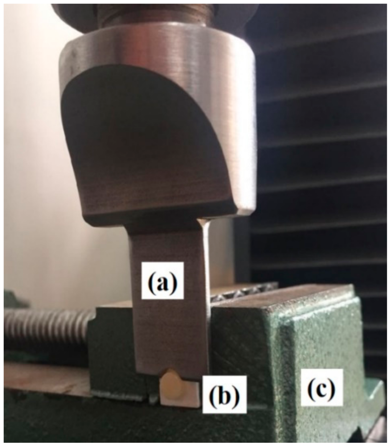
Figure 5.
Specimen tested by universal testing machine: (a) semicircular shaped piston; (b) zirconia specimen with veneering ceramic; (c) sample holder.
Figure 5.
Specimen tested by universal testing machine: (a) semicircular shaped piston; (b) zirconia specimen with veneering ceramic; (c) sample holder.

Figure 6.
SEM images of the surface morphology of the study groups at 100× magnification represent coating of composite alumina on zirconia substrate. E60S and E60P = zirconia cubes coated with <60 µm alumina IPS e.max glaze mixture. N60S and N60P = zirconia cubes coated with <60 µm alumina Noritake Cerabien ZR glaze mixture.

Figure 7.
Cross-section SEM images of all coated zirconia specimens: alumina composite layer and zirconia core.
Figure 7.
Cross-section SEM images of all coated zirconia specimens: alumina composite layer and zirconia core.

Figure 8.
XRD traces of alumina (<60 µm) and experimental groups of E60S, E60P, N60S, and N60P after surface treatments. The alumina (<60 µm) was heat-treated at 1100 °C for 2 h, with the peaks relating to portable document format (PDF) 81-1667 and corresponding to crystal alumina marked as •. Traces of coated zirconia by E60S, E60P, N60S, and N60P revealed a mixture of glass and crystalline phase of alumina PDF 81-1667 after heating at 1530 °C for 6 h.

Figure 9.
Spearman correlation analysis showing a significant correlation between shear bond strength and surface roughness (Spearman rho = 0.808, p < 0.001, n = 80).
Figure 9.
Spearman correlation analysis showing a significant correlation between shear bond strength and surface roughness (Spearman rho = 0.808, p < 0.001, n = 80).

Figure 10.
Representative SEM images of fractured zirconia in the study groups. The black arrows represent the remaining veneering ceramics in E60S and N60S and the fracture line of the remaining veneering ceramics in E60P and N60P.
Figure 10.
Representative SEM images of fractured zirconia in the study groups. The black arrows represent the remaining veneering ceramics in E60S and N60S and the fracture line of the remaining veneering ceramics in E60P and N60P.

Figure 11.
The energy dispersive spectroscopy (EDS) analysis for the glazes and veneering ceramics with their corresponding quantitative results.
Figure 11.
The energy dispersive spectroscopy (EDS) analysis for the glazes and veneering ceramics with their corresponding quantitative results.

Figure 12.
The EDS results of zirconia specimens with different surface treatments with their corresponding quantitative results of elements.
Figure 12.
The EDS results of zirconia specimens with different surface treatments with their corresponding quantitative results of elements.

Figure 13.
The EDS results of cross-sectional zirconia specimens with different surface treatments with their corresponding quantitative results of elements.
Figure 13.
The EDS results of cross-sectional zirconia specimens with different surface treatments with their corresponding quantitative results of elements.

Figure 14.
The EDS results for interface areas after SBS testing of different surface treatments indicate a different percentage of silicon (Si) considering the main element contained in the veneering ceramic study groups.
Figure 14.
The EDS results for interface areas after SBS testing of different surface treatments indicate a different percentage of silicon (Si) considering the main element contained in the veneering ceramic study groups.


Table 1.
Classification of experimental specimens according to surface treatments, liquids, and techniques used for coating.
Table 1.
Classification of experimental specimens according to surface treatments, liquids, and techniques used for coating.
| Groups n = 20 | Code * | Mixed Components/Powder | Mixed with Liquid | Technique |
|---|---|---|---|---|
| G1 | E60S | Alumina particle size < 60 µm + IPS e.max Ceram glaze powder | Alcohol | Airbrush spray |
| G2 | E60P | Alumina particle size < 60 µm + IPS e.max Ceram glaze powder | IPS e.max Ceram glaze liquid | Fine-brush paint |
| G3 | N60S | Alumina particle size < 60 µm + Noritake Cerabien ZR Glaze porcelain powder | Alcohol | Airbrush spray |
| G4 | N60P | Alumina particle size < 60 µm + Noritake Cerabien ZR Glaze porcelain powder | Noritake Cerabien ZR forming liquid | Fine-brush paint |
Note: * E = e. max Ceram; 60 = (<60 µm); N = Noritake; S = spray; P = paint; G = group.
Table 2.
Chemical compositions of the core and veneering materials according to the manufacturer’s information.
Table 2.
Chemical compositions of the core and veneering materials according to the manufacturer’s information.
| Material | Main Components (wt %) | Manufacturer |
|---|---|---|
| IPS e.max Ceram glaze powder | SiO2 61–68, Al2O3 5–8, Na2O 5–8, K2O 5–8, ZnO 2–4, other oxides 3.5–17, pigments 0–1 | Ivoclar-Vivadent, Schaan, Liechtenstein, Germany |
| IPS e.max Ceram glaze liquid | Butandiol (107-88-0 butane-1,3-diol) | Ivoclar-Vivadent, Schaan, Liechtenstein, Germany |
| IPS e.max Ceram | SiO2 50–60, Al2O3 16–22, K2O4 8, Na2O6 11, CaO, P2O5 and F: 2.0–6.0, other oxides: 1.5–8, pigments: 0.1–3 | Ivoclar-Vivadent, Schaan, Liechtenstein, Germany |
| Noritake Cerabien ZR glaze | SiO2 60–65, Al2O3 10–15, Na2O 5–10, K2O 10–15, CaO 0–3, BaO 0–2 | Noritake Dental Supply Co., Tokyo, Japan |
| Noritake Cerabien ZR forming liquid | Water, polyethyleneglycol additives | Noritake Dental Supply Co., Tokyo, Japan |
| Noritake Cerabien ZR, shade A2B | SiO2, Al2O3, Na2O, CaO, K2O, MgO, LiO2, B2O3 pigments | Noritake Dental Supply Co., Tokyo, Japan |
| Zirconium oxide (zirconium Zenostar®T (translucent)) | zirconium dioxide (ZrO2 + HfO2 + Y2O3) ≥ 99.0%, 4.5% < yttrium oxide (Y2O3) ≤ 6.0%, hafnium oxide (HfO2) ≤ 5.0%, aluminum oxide and other oxides ≤ 1.0% | Wieland Dental, Technik GmbH & Co. KG, Ivoclar Vivadent, Pforzheim, Germany |
| Commercial high purity α-Al2O3 powder | Al2O3 (100 nano particle) | Taimei Chemicals Co., Ltd., Tokyo, Japan |
Table 3.
Coating procedure parameters for airbrush spraying.
| Coating Parameters | Values |
|---|---|
| Mixing ratio Al2O3 (<60 µm)/glaze powder | 50 wt % |
| Mixing speed and duration | 500 rpm/min for 15 min |
| Air pressure for spraying | 37 psi (2.5 bars) |
| Dilution with pure ethanol | 1.5 mL |
| Distance between zirconia cube and airbrush nozzle | 10 cm |
| Spray time | 10 s |
| Nozzle diameter | 0.3 mm |
Table 4.
Firing schedules of the veneering ceramics.
| Veneering Ceramic | Pre-Drying | Firing Temperature | Holding Time | |
|---|---|---|---|---|
| Temperature | Time Heating Rate | |||
| Dentin (vacuum during heating) | – | – | – | – |
| IPS e.max Ceram | 400 °C | 90 °C/min for 4 min | 750 °C | 1 min |
| Noritake Cerabien ZR | 600 °C | 45 °C/min for 5 min | 930 °C | 1 min |
Table 5.
The mean values of Ra after surface treatment in different groups (n = 10).
| Groups | n | Mean (µm) | SD (±) | Category * |
|---|---|---|---|---|
| E60S | 10 | 1.154 | 0.160 | a |
| E60P | 10 | 3.177 | 0.204 | b |
| N60S | 10 | 1. 395 | 0.243 | c |
| N60P | 10 | 5.717 | 0.206 | d |
*: Values marked with different letters indicate significant differences (p > 0.001). SD = Standard deviation. * p-value tested by unpaired Mann-Whitney U test. SD = Standard deviation, Ra = surface roughness.
Table 6.
Tests between-subjects effects on the influence of treatment technique and coating materials on Ra.
Table 6.
Tests between-subjects effects on the influence of treatment technique and coating materials on Ra.
| Source | Type III Sum of Squares | Df | Mean Square | F | Significance |
|---|---|---|---|---|---|
| Corrected model | 133.196 a | 3 | 44.399 | 1048.299 | 0.000 |
| Intercept | 327.356 | 1 | 327.356 | 7729.209 | 0.000 |
| Technique | 100.648 | 1 | 100.648 | 2376.394 | 0.000 |
| Material | 19.335 | 1 | 19.335 | 456.517 | 0.000 |
| Treatment × materials | 13.214 | 1 | 13.214 | 311.985 | 0.000 |
| Error | 1.525 | 36 | 0.042 | – | – |
| Total | 462.076 | 40 | – | – | – |
| Corrected total | 134.721 | 39 | – | – | – |
a: R Squared = 0.989 (Adjusted R Squared = 0.988); Technique = airbrush spray and fine-brush paint; Materials = coating materials; Ra = surface roughness; Df = degree of freedom; F = F-Test.
Table 7.
Mean shear bond strength of four groups in dry conditions and water storage (n = 20).
| Groups | SBS Initial Value (n = 10) | SBS after Water Storage (n = 10) | Significant *** | ||||
|---|---|---|---|---|---|---|---|
| Mean (MPa) | SD (±) | Category * | Mean (MPa) | SD (±) | Category ** | ||
| E60S | 27.93 | 3.096 | a | 26.83 | 3.984 | d | 0.047 1 |
| E60P | 34.51 | 5.152 | b, c | 31.11 | 4.436 | d, e | 0.005 1 |
| N60S | 29.80 | 3.799 | b | 27.09 | 5.356 | d | 0.972 2 |
| N60P | 37.22 | 4.954 | c | 34.42 | 3.977 | e | 0.022 1 |
* p-value tested by unpaired Mann-Whiteny U non-parametric test. ** p-value tested by multiple comparison post hoc test. Identical letters (b, c, d, and e) in the same column indicate the value of SBS did not differ significantly p > 0.05. *** Significance indicates the tests between the SBS initial value and the SBS after water storage in the same row. 1: p-value tested by non-parametric Wilcoxon test. 2: p-value tested by paired t-test. SBS = shear bond strength. SD = standard deviation.
Table 8.
Tests between-subjects effects for the influence of surface treatment technique, materials and aging methods on SBS.
Table 8.
Tests between-subjects effects for the influence of surface treatment technique, materials and aging methods on SBS.
| SOURCE | TYPE III SUM OF SQUARES | DF | MEAN SQUARE | F | SIGNIFICANCE |
|---|---|---|---|---|---|
| CORRECTED MODEL | 822.633 a | 7 | 117.519 | 7.318 | 0.000 |
| INTERCEPT | 76,017.533 | 1 | 76,017.533 | 4733.470 | 0.000 |
| TECHNIQUE | 428.414 | 1 | 428.414 | 26.677 | 0.000 |
| MATERIALS | 291.963 | 1 | 291.963 | 18.180 | 0.000 |
| AGING | 10.404 | 1 | 10.404 | 0.648 | 0.424 |
| TREATMENT × MATERIAL | 47.911 | 1 | 47.911 | 2.983 | 0.088 |
| TREATMENT × AGING | 0.009 | 1 | 0.009 | 0.001 | 0.981 |
| MATERIALS × AGING | 13.737 | 1 | 13.737 | 0.855 | 0.358 |
| TREATMENT × MATERIALS × AGING | 30.197 | 1 | 30.197 | 1.880 | 0.175 |
| ERROR | 1156.290 | 72 | 16.060 | – | – |
| TOTAL | 77,996.456 | 80 | – | – | – |
| CORRECTED TOTAL | 1978.923 | 79 | – | – | – |
a: R Squared = 0.416 (Adjusted R Squared = 0.359). Technique = airbrush spraying and fine-brush paint. Materials = coating materials. Aging = before and after water storage.
Table 9.
Percentage of different modes of failure in each group in different aging conditions.
| Groups | Aging Method | Mode of Failure | ||
|---|---|---|---|---|
| Adhesive | Cohesive | Mixed | ||
| E60S | Initial | 80 | 0 | 20 |
| Water Storage | 90 | 0 | 10 | |
| E60P | Initial | 10 | 50 | 40 |
| Water Storage | 20 | 20 | 60 | |
| N60S | Initial | 60 | 0 | 40 |
| Water Storage | 70 | 0 | 30 | |
| N60P | Initial | 0 | 90 | 10 |
| Water Storage | 10 | 60 | 30 | |
© 2018 by the authors. Licensee MDPI, Basel, Switzerland. This article is an open access article distributed under the terms and conditions of the Creative Commons Attribution (CC BY) license (http://creativecommons.org/licenses/by/4.0/).
Share and Cite
MDPI and ACS Style
Muhammed, F.K.; Pollington, S.; Sun, X.; Abdullah, A.O.; Liu, Y. Novel Coatings on Zirconia for Improved Bonding with Veneer Ceramics. Coatings 2018, 8, 363. https://doi.org/10.3390/coatings8100363
AMA Style
Muhammed FK, Pollington S, Sun X, Abdullah AO, Liu Y. Novel Coatings on Zirconia for Improved Bonding with Veneer Ceramics. Coatings. 2018; 8(10):363. https://doi.org/10.3390/coatings8100363
Chicago/Turabian StyleMuhammed, Fenik K., Sarah Pollington, Xudong Sun, Adil O. Abdullah, and Yi Liu. 2018. "Novel Coatings on Zirconia for Improved Bonding with Veneer Ceramics" Coatings 8, no. 10: 363. https://doi.org/10.3390/coatings8100363
Note that from the first issue of 2016, this journal uses article numbers instead of page numbers. See further details here.