Cavitation Erosion and Jet Impingement Erosion Behavior of the NiTi Coating Produced by Air Plasma Spraying
by
 ,
,
Zhenping Shi
1,2, 
Jiqiang Wang
1,
Zhengbin Wang
1,
Yanxin Qiao
3,*,
Tianying Xiong
1 and
Yugui Zheng
1,* 1
CAS Key Laboratory of Nuclear Materials and Safety Assessment, Institute of Metal Research, Chinese Academy of Sciences, 62 Wencui Road, Shenyang 110016, China
2
School of Materials Science and Engineering, University of Science and Technology of China, 62 Wencui Road, Shenyang 110016, China
3
School of Materials Science and Engineering, Jiangsu University of Science and Technology, Zhenjiang 212003, China
*
Authors to whom correspondence should be addressed.
Coatings 2018, 8(10), 346; https://doi.org/10.3390/coatings8100346
Submission received: 17 July 2018
/
Revised: 24 August 2018
/
Accepted: 9 September 2018
/
Published: 28 September 2018
(This article belongs to the Special Issue Development and Characterization of Nanostructured Functional Coatings/Films)
Abstract
:Cavitation erosion and jet impingement erosion can result in a great loss of materials. NiTi alloy is a very promising candidate to acquire cavitation erosion resistance and jet impingement erosion resistance because of its superelasticity. Due to the high cost and poor workability of NiTi alloy, many people tried to overcome such drawbacks by preparing NiTi coatings on the basis of deteriorating the good properties as little as possible. From the aspect of the application of NiTi coating, the erosion resistance should be evaluated comprehensively. One of these evaluations involves the comparison of cavitation erosion resistance and jet impingement erosion resistance of NiTi. This evaluation has not been made thus far. Thus, in this study, the NiTi coating was prepared by air plasma spraying (APS) using pre-alloyed NiTi powder. Its microstructure, chemical composition and phase transformation were identified. Cavitation erosion behavior and jet impingement erosion behavior of the as-sprayed NiTi coating were compared. The results showed that the coating exhibited better jet impingement erosion resistance than cavitation erosion resistance. This was attributed to the oxides, impurities, cracks and pores that existed in the coating, whose effects on deteriorating the cavitation erosion were far greater than those worsening the jet impingement erosion.
1. Introduction
Cavitation erosion and jet impingement erosion often occur in high speed and ultrasonic mixing systems. To repair the damage caused by cavitation erosion and jet impingement erosion, millions of pounds have to be expended every year [1,2,3].
In general, when the hydrodynamic pressure changes, vapor cavities are formed. The subsequent collapse of these unstable bubbles creates the shock wave and/or micro-jet in turbulent flows, which can impact surfaces and initiate cavitation erosion damage [4,5,6,7]. Typically, jet impingement erosion is defined as the acceleration or increase in the rate of metal/alloy deterioration caused by the mechanical damage due to the impacting of solid particles. Such erosion involves in surface damage and severe material loss caused by the repetitive impact of hard erodent particles [8,9,10,11].
NiTi alloy is a very promising candidate to acquire both cavitation erosion resistance and jet impingement erosion resistance [12]. The nearly equiatomic NiTi intermetallic compounds, called the shape memory alloys, have unique properties such as shape memory effect, superelasticity, high corrosion resistance and fatigue strength [13,14,15]. For wear applications of shape memory alloys, the superelasticity has been considered as the major property. The martensitic transformation may also be stress-induced, giving rise to the superelastic effect. The superelastic effect occurs by the application of stress when the materials are in the temperature range of thermally stable austenite. This property allows for the material to undergo a significant deformation during loading, with full recovery of its shape upon unloading. For the particular case of NiTi shape memory alloys, the stress-induced martensite is highly deformable by twin boundary migration when external stresses are applied, leading to the reorientation of the martensitic plates [16]. In principle, the mass loss in the processes of both cavitation erosion and jet impingement erosion originates from either the impact stress (from the shock wave, micro-jet, or hard erodent particles) or the crack propagation. The superelasticity of the NiTi alloy can mitigate the effect of the impact stress and retard the crack propagation, which can result in high cavitation erosion and jet impingement erosion resistance. In recent years, the high cavitation erosion resistance of the NiTi alloy has already been demonstrated by several authors. Many authors reported that both austenite and martensite contributed to the high cavitation erosion resistance of NiTi alloy [13,17,18]. Wu et al. [14] reported that the variants accommodation, pseudoelasticity of stress-induced martensite and high work-hardening rate could improve the erosion resistance of NiTi alloy. Shida et al. [19] showed that the erosion resistance of the NiTi alloy was strongly dependent on chemical composition and microstructure, but not on hardness.
However, the high cost and poor workability restrict the wide application of NiTi alloy. In order to conquer its shortcomings, people have tried to prepare the NiTi coatings on the basis of sacrificing the superior properties of NiTi alloy as little as possible. Many investigations have been carried out to prepare NiTi coatings or films with cavitation and erosion resistance. These NiTi coatings are generally prepared by explosive welding [20,21], low pressure plasma spray process (LPPS, used to be called VPS) [4,15,22,23], air plasma spraying (APS) [22,23,24], high velocity oxy-fuel spray (HVOF) [22,23,24,25], tungsten inert gas (TIG) [26], laser [27,28], laser plasma hybrid spraying [29,30], sputter depositing [31], cold spraying [32,33] and modified high-velocity oxygen fuel spraying process (so called low temperature HVOF) [34,35,36,37]. Many researchers studied the cavitation erosion resistance of NiTi coatings. For example, Cheng et al. [26,27,28] reported that the cavitation erosion resistance was ranked in descending order as: NiTi plate > 316-NiTi-Laser > 316-NiTi-TIG > AISI 316L. However, almost no investigations focused on the resistance of jet impingement erosion. Furthermore, no one made a comparison of the cavitation erosion resistance and the jet impingement erosion resistance of NiTi coatings, which is useful for the application. Therefore, this comparison is worthwhile.
In the present work, our purpose is to make a comparison of the cavitation erosion resistance and the jet impingement erosion resistance of NiTi coatings. We are interested in whether the NiTi coating can hold the excellent characteristics of the NiTi alloy. The APS is used to prepare the NiTi coating because it does not need a vacuum chamber and the shape of the workpiece is not limited, although the coating made by this method has more oxides, pores and impurities compared to that made by LPPS. The microstructure, chemical composition and defects of the as-prepared NiTi coating are evaluated, and the cavitation erosion resistance and jet impingement erosion resistance are compared.
2. Materials and Methods
2.1. Materials
In the present work, NiTi powder was used, which was obtained from Beijing AMC Powder Metallurgy Technology Co., Ltd. (Beijing, China). The powder was prepared using commercial NiTi rods by electrode induction inert gas atomization. The chemical compositions of NiTi powder are listed in Table 1. Figure 1b shows the XRD patterns of NiTi powder. The main phase is austenite B2 (NiTi). No other intermetallic compounds, carbides or oxides are found, which may be due to the low content of these impurities. Figure 1a shows the morphology of NiTi powder used as a starting material for APS processing. The powder has a spherical shape, and its degree of sphericity is 0.89. That means excellent flowability for the powder feeding. The particle size of the powders was measured by the laser particle analyzer. The d10, d50 and d90 values are 53.20 μm, 78.13 μm and 124.70 μm, respectively. These values are suitable for APS. The relatively large diameter of the powders can ensure the flowability of the powders and reduce the phenomenon of overburning.
In addition, the NiTi alloy plate was used as the comparing material, whose phase and chemical composition are austenite B2 and Ni50.5Ti49.5 at %, respectively.
2.2. Preparation of Coating
The 304 stainless steel was selected as the substrate with 140 mm in length, 50 mm in width and 5 mm in thickness, which was prepared by descaling and blast cleaning before APS. The descaling can clean the surface of substrate, and the blasting with corundum can improve the roughness of substrate. The chemical composition of 304 stainless steel is listed in Table 2.
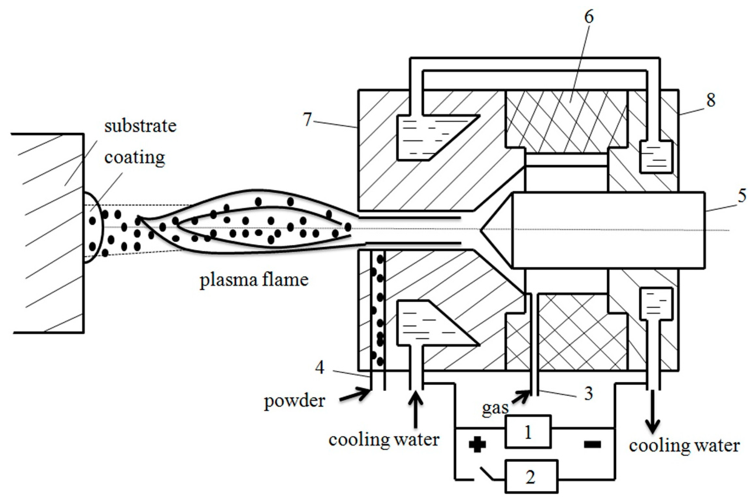
The APS equipment is homemade, mainly including the power supply, control cabinet, spray gun, powder feeder, circulating water cooling and gas supply systems. The schematic diagram of the APS system is shown in Figure 2. The inert gases are taken to the plasma generator (plasma gun), and these inert gases are heated and activated when they pass through the direct current arc between positive and negative poles in the plasma gun. Therefore, this ionized the inert gases. This process produces high temperatures and a high-speed plasma arc flow. The temperature of the plasma arc is so high that the powders are heated to a molten or semi-molten state. These powders impact the substrate in the high speed plasma arc flow, resulting in the formation of the coating.
Before the spraying process, the substrate is heated by the plasma arc flow without powder feeding. In the process of spraying, the plasma gun moves on a fixed route. When the route is complete and the spray completely covers the surface of the substrate, this is one spraying cycle. The spraying parameter is shown in Table 3.
2.3. Microstructure, Chemical Analysis and Phase Transformation
The microstructure of the powder was investigated by optical microscope (OM) (Carl Zeiss Axio Observer Z1 m, ZEISS, Oberkochen, Germany). The samples and powders were etched by a solution of 100 mL distilled water, 20 mL hydrofluoric acid and 50 mL nitric acid. The micro-hardness of the NiTi coating and NiTi plate was measured using a HV-1000 micro-hardness tester (laizhou hengyi tester equipment Co., Ltd., Laizhou, China). The hardness profile was acquired by means of a micro-hardness test at a load of 500 g and a loading time of 10 s. The morphology and chemical composition of the specimen were investigated by using a FEI XL30 field emission gun scanning electron microscope (FEG–SEM, FEI, Hillsboro, OR, USA). In addition, X-ray diffraction (XRD) using a Righaku D/max 2400 diffractometer (Rigaku Corporation, Tokyo, Japan)with monochromated Cu kα radiation (λ = 0.1542 nm) and differential thermal scanning analysis (DSC, STA 449 C, NETZSCH, Free State of Bavaria, Germany) were used to characterize microstructures, analyze chemical compositions and evaluate phase transformation.
2.4. Cavitation Erosion Test
In the cavitation erosion test, the ultrasonically vibratory apparatus was used. The test was carried out according to the ASTM G32-10 (2010) standard [37]. The equipment consists of an ultrasonic liquid processor (Q700) from Qsonica, LLC (53 Church Hill Rd., Newtown, CT, USA). A sonicator system is comprised of three major components: the generator, the converter and the horn (also known as a probe). The standard probe (probe 4420) was selected. The probe is made from titanium and the tip diameter is 13 mm. The area of the bottom surface of the probe was bigger than the top surface of the sample to ensure that the whole top surface of the sample suffers from the cavitation erosion. The vibration frequency of the probe was 20 kHz and the amplitude was 30 μm. Before the cavitation erosion test, the sample was ground with SiC emery paper up to grade 2000, washed in the alcohol, dried in hot air, and weighted using an analytical balance with an accuracy of 0.1 mg. The sample was submerged in the distilled water, and was placed at a distance of 0.5 mm to the lower surface of the probe, which was immersed into the test medium to a depth of 15 mm. The temperature of the distilled water was maintained at about 20 °C using the cooling water. The erosion damage of the samples was evaluated in terms of the mass loss. Each test was repeated at least three times to ensure the reproducibility.
2.5. Jet Impingement Erosion Test
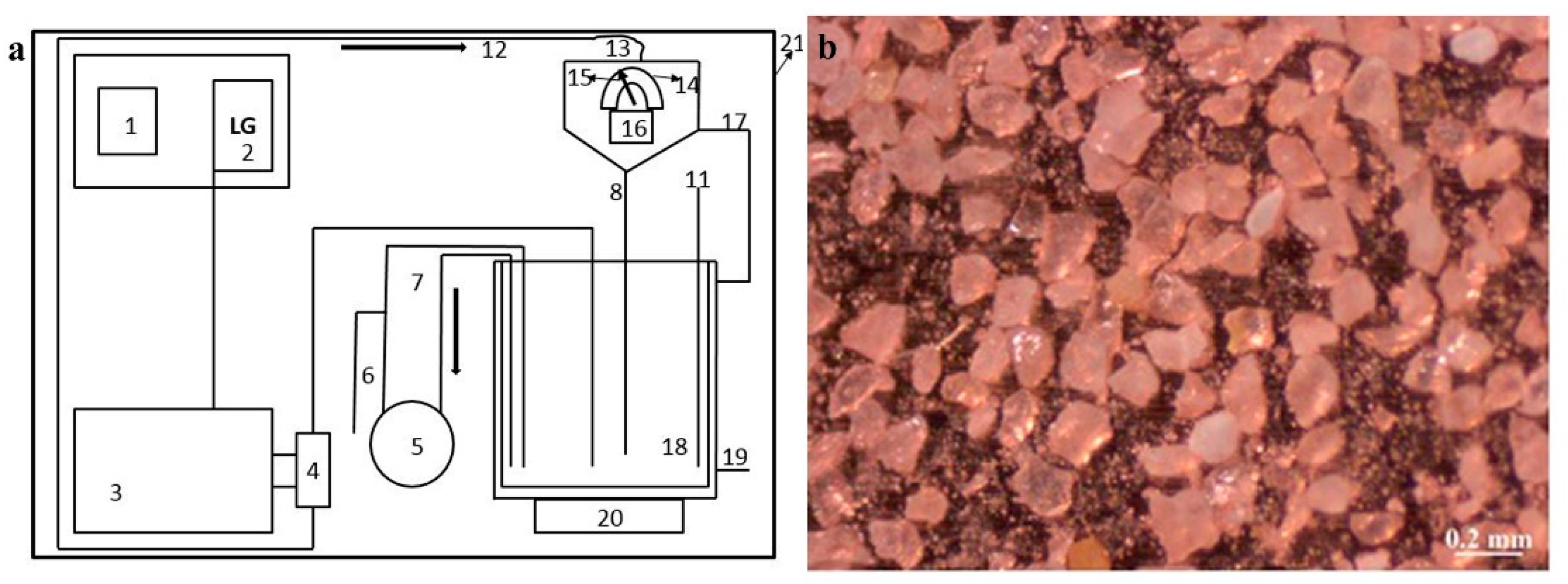
The jet impingement erosion equipment was homemade. The schematic diagram of the jet apparatus for erosion corrosion is shown in Figure 3a [38]. In the process of jet impingement erosion, the diameter of the nozzle was 3 mm. The sample was placed at 5 mm from the nozzle. The impact angle was set at 90°. Tap water containing 2 wt % silica sand (70–150 mesh) was used as the test medium. The shape of the silica sand was irregular and angled, as shown in Figure 3b. It is a recycled abrasive erosion test during each run and the new silica sand was used for each run. The flow velocity was 15 m/s throughout the whole process of the jet impingement erosion. Before the jet impingement erosion test, the samples were ground with SiC emery paper up to grade 2000 and washed in alcohol. The samples were dried before the tests, and weighed using an analytical balance with an accuracy of 0.1 mg. The erosion damage to the samples was evaluated in terms of the mass loss. Each test was repeated at least three times to determine reproducibility.
3. Results and Discussion
3.1. Microstructure, Chemical Analysis and Phase Transformation
The hardness profile was acquired by the means of a micro-hardness test. The hardness of the NiTi coating and the NiTi plate is 549.1 HV and 307.7 HV, respectively. Figure 4a shows the cross-sectional microstructure of the NiTi powder without etching by an optical microscope. Some pores exist in the interior of powder. These pores are formed in the process of the inert gas atomization of commercial NiTi rods using electrode induction. The molten powders have an affinity to the gas, and the gas dissolves into the molten powder. When the powders cool fast, the integrated gas has no time to escape completely. The residual gas causes the formation of these pores. The existence of these pores in the powders is taken as one of the reasons for the pores existing in NiTi coating, which will be shown later. Figure 4b shows the cross-sectional microstructure of NiTi powder after etching. The powders consist of equiaxed crystal. Figure 1b shows that the equiaxed crystal is austenite B2. Figure 4c shows the surface microstructure of the NiTi plate after etching. The second phases, oxides and pores are found on the surface of the NiTi plate before the cavitation erosion test.
Figure 5 shows the back scattered electron (BSE) microstructure of NiTi coating, in which un-melted powders, parallel cracks, perpendicular cracks, pores, oxides and impurities can be found. The un-melted powders retain the state of the starting powders. The length of the plasma arc flow is short, making it very easy for air entrainment. Then, it can induce the heat inhomogeneity of the particles in the process of APS. As a result, the partial particles are melted while the other partial particles are semi-molten. Under the effect of the plasma arc flow, the melted particles form the lamellae when the particles hit the substrate. However, the un-melted particles are inlaid in the coating and keep the initial shape of the particles. The existence of pores has a great influence on the mechanical and corrosion properties of the coating. There are two kinds of pores, macropores and micropores. The macropores exist between the lamellae. The incomplete filling of the droplets when the droplets impact substrate and the insufficient flattening of the unmelted particles are the reasons for the forming of macropores. The micropores are formed for the following reasons. The first one is the insufficient wetting of the surface of the existing coating. The second is the existing pores in the inner of starting powders. The third is that the integrated gas has no time to escape when the droplets cool at a high velocity. The formation of oxides and impurities results from the metallic droplets reacting with the atmospheric oxygen during their flight to the substrate.
The cracks in the coating perpendicular to the substrate are through the individual lamellae and are perpendicular to the lamellae. The forming of these kinds of cracks is due to the cooling of the droplets at a high velocity. In the process of APS, the cooling and flattening of the droplets are two separate processes. When the droplets with high temperatures impact the previously deposited lamellae, cooling and flattening can happen. The cooled and flattened droplets will shrink, but the previously deposited lamellae will limit this shrinking. It will induce staining inside the coating, and cracks will form consequently so the stress can be released. The reason the cracks in the coating form parallel to the substrate is the sheer stress generating at the interface between the freshly impacted lamellae and the previously deposited surface.
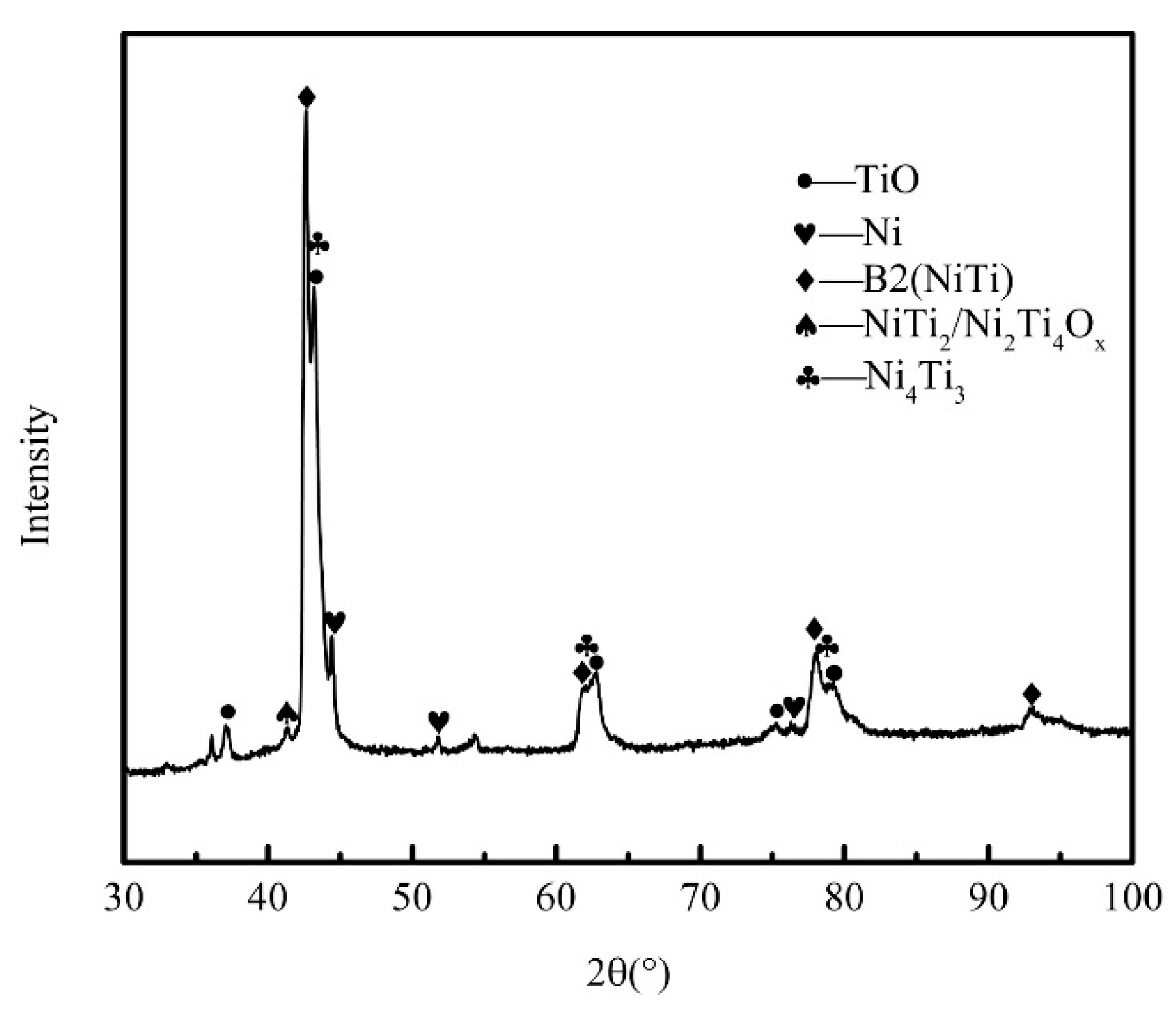
Figure 6 shows the EDS analysis of the NiTi coating. The dark grey areas C and D are the oxides. The oxide layer around each lamella can reduce the area fraction of intimate contact. The light grey area A is the austenite phase B2. The white area B is solid solution nickel with a very small amount of titanium. This result can be verified in the XRD patterns as shown in Figure 7. The austenite phase B2 of area A occupies the main part of the coating.
Table 4 shows the chemical compositions of the selected area from the NiTi coating. Combining the results of the XRD patterns as shown in Figure 7, the areas C and D may be the TiO and NiTi2/Ni2Ti4O3. Line scanning of the selected area from the NiTi coating is shown in Figure 6, in which titanium, nickel and oxygen elements are the foci. Because the titanium has an affinity for oxygen, the oxygen content increases with the titanium content. In the dark grey area, the content of titanium is more than that of nickel. In the white area, the content of nickel is more than the content of titanium. The XRD pattern of coating shown in Figure 7 also confirms that Ni4Ti3 exists in the coating. It is not found in Figure 5 (BSE microstructure of NiTi coating with a magnification). The Ni4Ti3 may be very small and is only distributed in area A as shown in Figure 6. Compared with the diffraction peak of the starting powder, the diffraction peak of the as-sprayed coating is obviously broadened as shown in Figure 7. The starting powder impact the substrate in high speed during the process of APS. The particles with high temperatures have severe plastic deformation. These could result in dynamic recrystallization and the emergence of high deformation regions. The grain refinement phenomenon leads to a decrease in the grain size and widens the diffraction peak. In addition, the plastic deformation of particles results in the microstrain between grains or intergranular grains. The crystal plane space and the diffraction angle of grains are changed. The diffraction peaks of different diffraction angles are superimposed, so the measured diffraction peaks broaden.
Figure 8 shows the DSC curve of (a) NiTi powder and (b) as-sprayed NiTi coating. The DSC peak of NiTi coating widens compared with that of the NiTi powder. Ni4Ti3, NiTi2/Ni2Ti4O3, Ni and TiO, can induce the fluctuations of the Ni:Ti ratio. This could be the main reason for the broadening of the NiTi coating DSC peak.
3.2. Cavitation Erosion Test
Figure 9a shows the cumulative mass loss with time for cavitation erosion of the NiTi coating and the NiTi plate. The mass loss of the NiTi coating was far greater than that of the NiTi plate. After testing for 30 h, the mass loss of the NiTi coating was 5.2 times that of the NiTi plate. There was no incubation period for the cavitation erosion of NiTi coating. In contrast, the mass loss of NiTi plate was still in the incubation period.
Figure 9b shows the XRD pattern of (A) as-sprayed NiTi coating and (B) NiTi coating after 30 h cavitation erosion. Compared to the as-sprayed NiTi coating, the NiTi coating after 30 h cavitation erosion had no Ni and NiTi2/Ni2Ti4O3. It indicated that Ni and NiTi2/Ni2Ti4O3 on the surface of the NiTi coating were removed after 30 h cavitation erosion. The austenite B2 is still in the main phase.
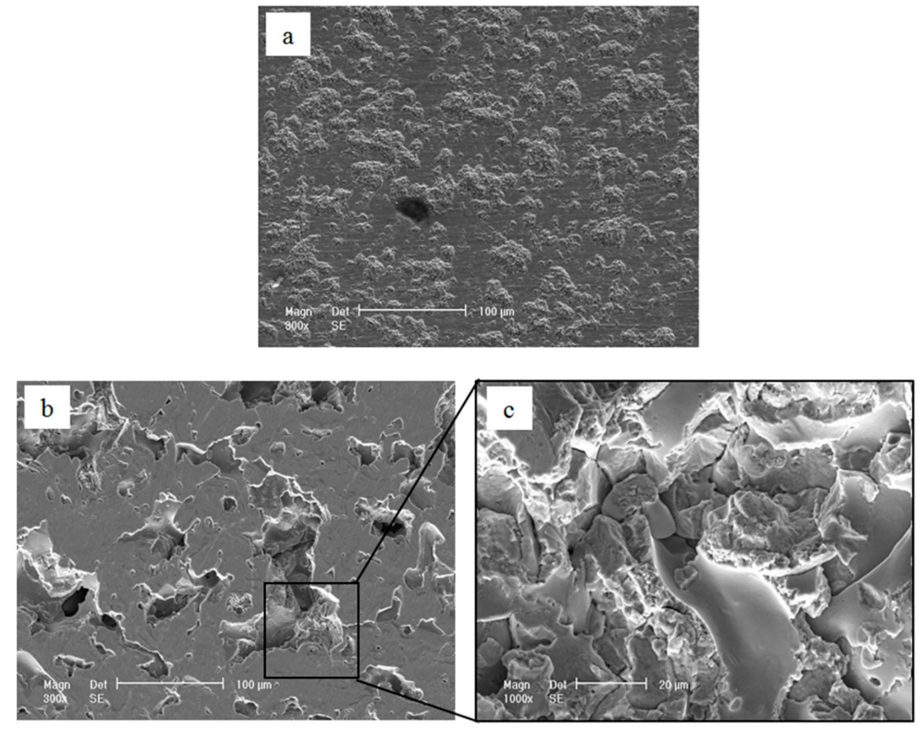
Figure 10 shows the surface morphologies of the NiTi plate and the NiTi coating after 30 h cavitation erosion. Some eroded areas and some little pits can be detected on the surface of NiTi plate. Even so, there are still some intact areas on the surface. The eroded areas look like popcorn. Some weak points like second phases and oxides in the NiTi plate (Figure 4c) could be removed easily in the initial stage of cavitation erosion. These little pores could be cavitation sources even when the quantity of the pores is small. Thus, the cavitation damages are mainly the location of these defects.
In Figure 10b, some huge and deep pits exist on the surface of the NiTi coating after 30 h cavitation erosion. There are also some intact areas on the surface. The diameter of some pits is more than 100 μm. The magnification of selected areas for the NiTi coating after 30 h cavitation erosion is shown in Figure 10c. The shape of the fracture shows typical brittle features. Some cracks existed in the bottom of the pit.
The shock wave or micro-jet generated in the bubble collapse resulted in the plastic deformation of materials. The repeated plastic deformation of the material’s surface caused the appearance of toughness reduction. Due to the continuous impacting of the shock wave or micro-jet, cracks were generated near the cavitation pits. The cracks expanded to defects at the inner part. The cracks continued to expand, and as a result, the particles were shed. The cavitation pits gradually expanded and connected to pieces. Eventually the whole surface is damaged by cavitation erosion.
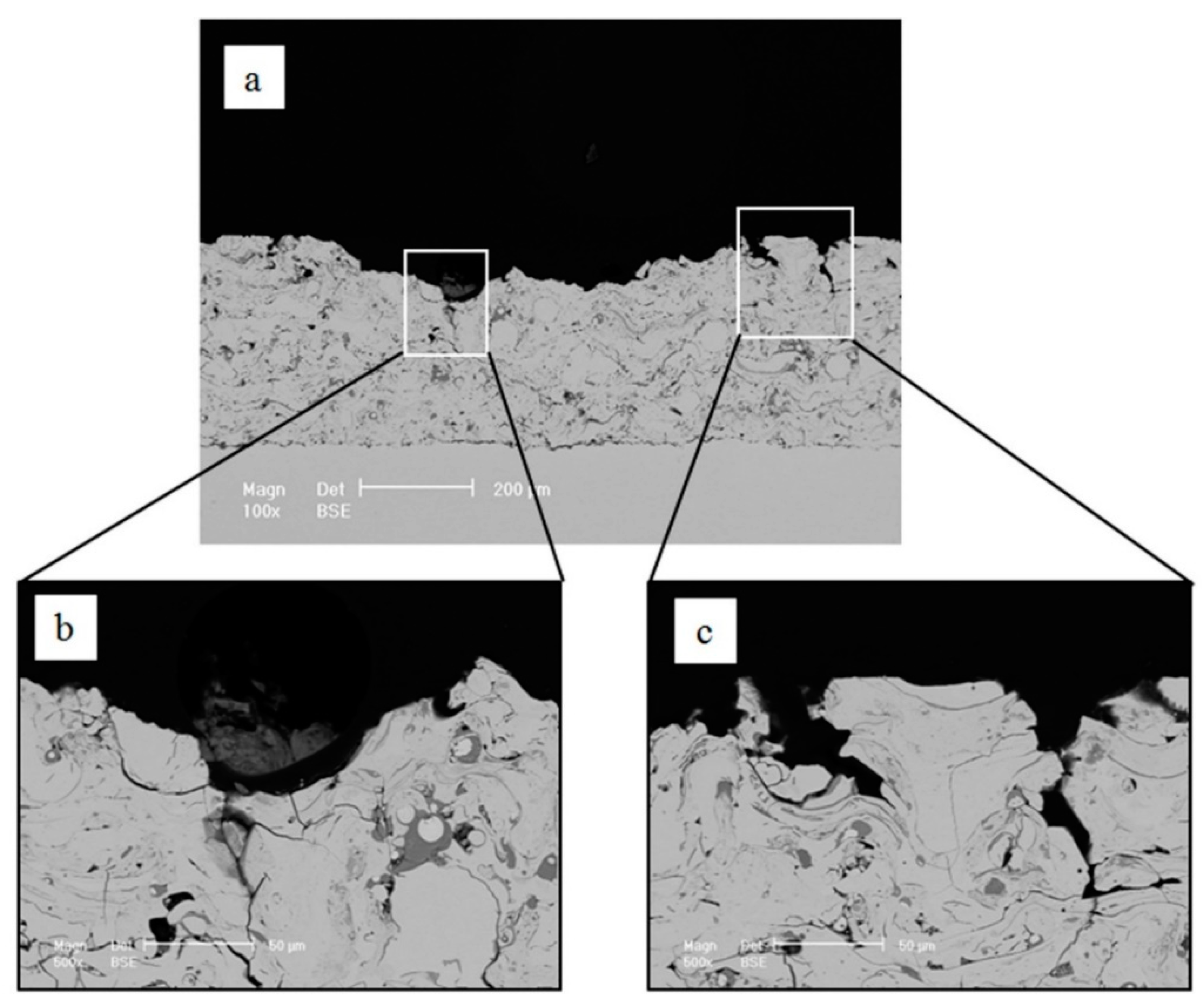
Figure 11 shows the cross-sectional microstructure of the NiTi coating after 30 h cavitation erosion. In general, the cavitation erosion damage, first happens in or around the defects [39]. The failure mechanism of NiTi coating is proposed in Figure 12 based on the results of Figure 10 and Figure 11. The removal of material is considerably slower in defect-free areas than in porous areas. Some weak points could be removed easily in the initial stage of cavitation erosion. In Figure 11a, the damaged areas are huge. The depth of some pits is more than 150 μm. At the bottom of the pits, there is a crack perpendicular to lamellae, as shown in Figure 11b. The formation of this pit should result from this kind of crack. Some cracks perpendicular to the lamellae had already existed within the prepared NiTi coating before the cavitation erosion test (Figure 5). The cavitation erosion damage will inevitably initiate at, or around, such cracks, and then these cracks will propagate and expand during the cavitation erosion test. The pits become deeper and deeper with the propagating of such cracks. Furthermore, Figure 11c documents that the two pits advance along a crack. When they encounter the cracks parallel to lamellae as shown in Figure 5, the two pits will connect with each other. Accordingly, the NiTi coating will suffer from severe cavitation erosion damage.
For the NiTi plate, despite the time spent in the cavitation test, there is little mass loss. Only some particles that are easy to peel off are removed in the initial period [6,13]. It should be emphasized that the incubation period is quite long. This should be ascribed to the superelasticity of the NiTi plate. During the cavitation erosion test, the stress induced martensitic transformation will occur in the austenite phase under external stress. The stress-induced martensite is highly deformable by twin boundary migration when external stresses are applied, leading to the reorientation of the martensitic plates [4,13]. Through the two kinds of mechanism, most of the energy generated by the bubble collapse is absorbed, which reduces the effect of the stress and retards the crack propagation.
In contrast, the prepared NiTi coating is destroyed by cavitation erosion at a faster rate and has no cavitation incubation period during the whole process of cavitation erosion. There are three main reasons for this. First, the coating contains large amounts of the oxides and impurities. These brittle oxides and impurities have poor cavitation erosion resistance. They are peeled off at the initial stage of cavitation erosion. There are many microcracks in these brittle materials. The external stress can easily cause stress concentration near the microcracks. When the stress exceeds the critical value, the cracks expand rapidly, which results in the brittle fracture of materials. The repeated stress from the shock wave or micro-jet acting on the surface is huge during the cavitation erosion, which causes the microcracks’ propagation. The oxides and impurities encounter brittle fracture and fall off. Second, after the surface oxides and impurities are all peeled off, the cavitation damage will develop along the longitudinal direction through the cracks perpendicular to the lamellae. The oxides and impurities completely fall off and form the cavitation pits. In the cavitation pits, the cracks propagate along the interface of particles. This causes the cavitation damage areas to increase, and some new particles are exposed and the damage repeats by the mechanism referenced above. Third, some pores exist in the NiTi coating. The cavitation bubbles are expected to nucleate and grow easily around these pores. The small damage pits are continuously attacked during further cavitation and grow wider and deeper [14].
In conclusion, the oxides, impurities and pores are the key reason for the severe cavitation erosion damage of the prepared NiTi coating.
3.3. Jet Impingement Erosion Test
Figure 13a shows the cumulative mass loss of jet impingement erosion for the NiTi coating and the NiTi plate in tap water with 2 wt % silica sand for 12 h. From the data point of view, the jet impingement erosion resistance of the coating is slightly better than that of NiTi plate.
Figure 13b shows the micro-beam XRD pattern of the as-sprayed NiTi coating, and before and after the 12 h jet impingement erosion. The reason for using the micro-beam XRD pattern with cobalt as the target is that the eroded surface of the jet impingement erosion is so small that it cannot be detected by conventional XRD. The Ni and NiTi2/Ni2Ti4O3 are not found in the XRD pattern of NiTi coating after 12 h jet impingement erosion. The main phase is still austenite B2, and the TiO and Ni4Ti3 are also found in the XRD pattern. The peak intensity of austenite B2 of the as-sprayed NiTi coating after 12 h jet impingement erosion become weak compared to the original coating. The reason may be that the partial austenite B2 on the surface of the coating transforms to martensite B19’ and partial B19’ transforms to martensitic variant B19 after 12 h jet impingement erosion. The B19’ or B19 is not found in the XRD pattern, which is probably due to the small amount of B19’ and B19.
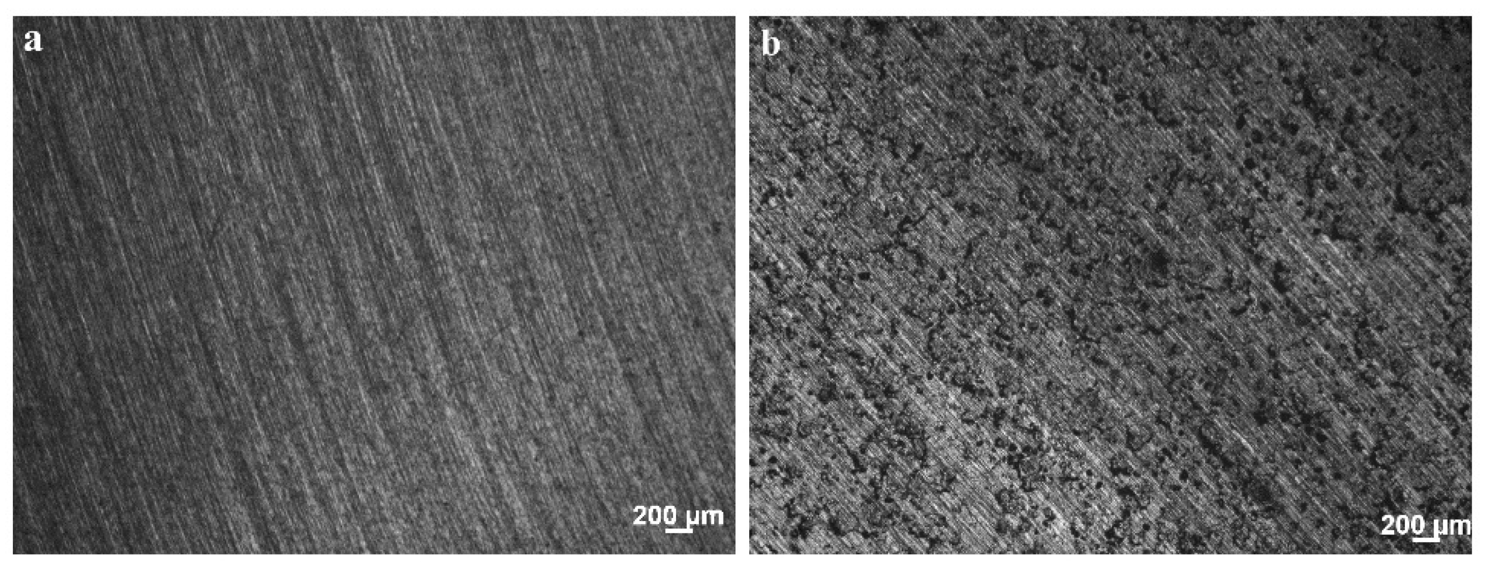
Figure 14 shows the surface morphology of the NiTi plate and the NiTi coating before the jet impingement test. Figure 15 shows the surface morphology of the NiTi plate and the NiTi coating after 12 h jet impingement erosion. The shape of impingement particles is irregular, which will cause severe damage. There is no intact place on the surface. It exhibits the typical damage features of ductile material in the jet impingement erosion. On the surface of the NiTi plate and the NiTi coating after 12 h jet impingement erosion, there is a small number of ploughed scratches, long furrows and ridges. But there are many overlaps and irregular concavities on the surface. At the high impinged angle, the material damage accumulation comes from fatigue, shear localization, microforging and extrusion processes. Lots of indented concavities and thin platelets come from this combined deformation of microforging and extrusion. These protruding thin platelets will be partially impinged off by the subsequent impinged particles. When the material encounters the subsequent impinged particles, many overlapping irregular concavities and residual protruding thin platelets attach on-to the nearby surface. In fact, these impinged surface morphologies are consistent with those reported for ductile materials [19,40].
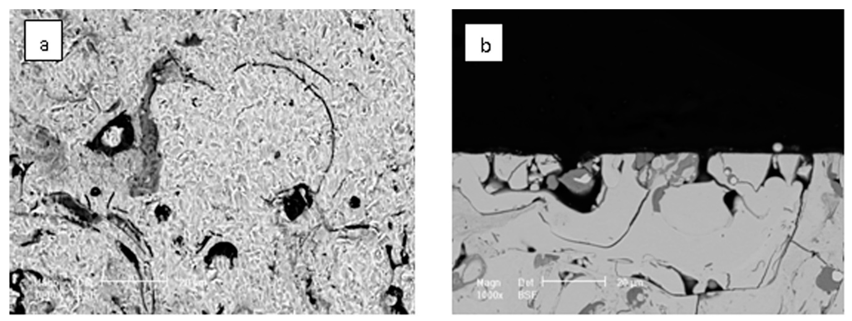
Like the cavitation erosion test, the stress induced martensitic transformation occurs in the austenite phase under external stress during the jet impingement erosion test. When external stresses are applied, the stress-induced martensite transforms to the martensite variant that has the most favorable orientation through the formation of a martensite twin boundary slip. In the NiTi plate or NiTi coating, the austenite phase B2 is the main component. The superelasticity of the austenite would also stabilize the fatigue crack tips and hinder the crack propagation. This mechanism partially relieves the impact load and accommodates the impact strain elastically. Figure 16 shows the BSE surface micrographs and cross-sectional microstructure of the NiTi coating after 12 h jet impingement erosion. Some small pits can be detected. Some of these pits existed before the jet impingement erosion test, while some were formed due to the solid particle impacting. No apparent falling off the bulk material can be recognized. During the process of jet impingement erosion, the oxides and impurities are impacted by the solid particle impacting. Although the impacting will cause mass loss, the existence of brittle phases is discrete and does not allow pits to connect. The mass loss caused by the oxides and impurities is small. In addition, the existence of pores in the coating has a certain buffer effect on the impact of the particles. So, the jet impingement erosion resistance of the NiTi coating is equivalent of that of the NiTi plate.
Compared with the NiTi plate, the NiTi coating presents inferior resistance to cavitation erosion. In contrast, the NiTi coating shows almost equivalently superior jet impingement erosion resistance. What results in such differences? The reasons are as follows.
First, during the cavitation erosion process, the velocity of the shock wave or micro-jet caused by the bubble collapse is very high. It is far greater than the velocity of particles during the jet impingement erosion process. In addition, the shock wave or micro-jet often impacts the material surface with high energy and an instantaneous high temperature. Therefore, the material damage caused by the shock wave or the micro-jet is far greater than that of the impactive particles during the jet impingement erosion process. During the cavitation erosion process, especially when defects exist in the coating, the oxides and impurities can easily be broken down by the shock wave or micro-jet to form a pit. The pits will become cavitation sources. Therefore, they can cause more bubble collapses near the pits. In addition, the energy carried by the shock wave or the micro-jet can make the existing cracks propagate and expand. This can cause a large amount of the material to fall off. During the jet impingement erosion process, the oxides and impurities will also be impacted. The impact strength is far less than the impact strength of cavitation erosion. The oxides and impurities rarely fall off during the jet impingement erosion process. The high hardness of these hard and brittle phases can help improve the resistance to erosion. In the process of jet impingement erosion, there is no phenomenon of bulk material falling off.
Second, there are some pores in the NiTi coating. The pores will become a cavitation source. The pores could cause more bubble collapses near the pores. The bubbles can collapse at the bottom of the pores. The shock wave or the micro-jet will impact the bottom of the pores and make the pores bigger and deeper. In the process of jet impingement erosion, the existence of pores in the coating has a certain buffer effect on the impact of the particles.
All in all, the effects of oxides, impurities, cracks and pores in the coating on the cavitation erosion are far greater than those on the jet impingement erosion. The NiTi plate has a relatively small quantity of defects compared with the NiTi coating. So, the NiTi coating presents inferior resistance to cavitation erosion but almost equivalently superior jet impingement erosion resistance compared with the NiTi plate.
In future research, it is important to optimize the parameters of APS which are related to the quantity of the oxides, impurities, cracks and pores in the NiTi coating. In addition, the interaction between the electrochemical corrosion behavior of the NiTi coating and cavitation erosion and jet impingement erosion also needs to be studied.
4. Conclusions
The NiTi coating produced by APS from the pre-alloyed NiTi powder is prepared successfully. The main phase of the NiTi coating is austenite B2. In addition, unmelted powders, parallel cracks, perpendicular cracks, pores, oxides and impurities have been found in the NiTi coating.
During the cavitation erosion process, the velocity of the shock wave or micro-jet caused is far greater than that of the particles during the jet impingement erosion process. The energy carried by the shock wave or the micro-jet can make the existing cracks propagate and expand. During the jet impingement erosion process, the oxides and impurities rarely fell off.
In addition, there are pores in the NiTi coating. The pores will become a cavitation source during the cavitation erosion process. In the process of jet impingement erosion, the existence of pores in the coating has a certain buffer effect on the impact of the particles.
All in all, the effects of defects in the NiTi coating on the cavitation erosion are far greater than those on the jet impingement erosion. As the result, the NiTi coating presents inferior resistance to cavitation erosion and nearly equivalently superior jet impingement erosion resistance compared with the NiTi plate.
Author Contributions
Conceptualization: Z.S. and Y.Z.; Methodology, Z.S. and Y.Z.; Validation, Y.Q. and Y.Z.; Formal Analysis, Y.Z. and Z.W.; Investigation, Z.S., J.W., Y.Q., T.X. and Y.Z.; Resources, Y.Q. and Y.Z.; Data Curation, Z.S.; Writing-Original Draft Preparation, Z.S.; Writing-Review & Editing, Z.S., Y.Z. and Z.W.; Visualization, Z.S.; Supervision, Y.Z.; Project Administration, Y.Z. and T.X.
Funding
This research was funded by National Key R&D Program of China (2018YFC0808503).
Conflicts of Interest
The authors declare no conflict of interest.
References
- Carlton, J.S. Marine Propellers and Propulsion, 1st ed.; Butterworth Heinemann: Oxford, UK, 1994; p. 199. ISBN 9780080971230. [Google Scholar]
- Hammit, F.G. Cavitation and Multiphase Flow Phenomena; McGraw-Hill: New York, NY, USA, 1980; p. 222. ISBN 0070259070. [Google Scholar]
- Wood, R.J.K. Erosion–corrosion interactions and their effect on marine and offshore materials. Wear 2006, 261, 1012–1023. [Google Scholar] [CrossRef]
- Stella, J.; Schüller, E. Cavitation erosion of plasma-sprayed NiTi coatings. Wear 2006, 260, 1020–1027. [Google Scholar] [CrossRef]
- Bitzer, M.; Rauhut, N. Cavitation-resistant NiTi coatings produced by low-pressure plasma spraying (LPPS). Wear 2015, 328, 369–377. [Google Scholar] [CrossRef]
- Lavigne, S.; Pougoum, F. Cavitation erosion behavior of HVOF cavitec coatings. Wear 2017, 386, 90–98. [Google Scholar] [CrossRef]
- Sreedhar, B.K.; Albert, S.K. Cavitation damage: Theory and measurements—A review. Wear 2017, 372, 177–196. [Google Scholar] [CrossRef]
- Rajahram, S.S.; Harvey, T.J. Investigation of erosion–corrosion mechanisms of UNS S31603 using FIB and TEM. Tribol. Int. 2012, 46, 161–173. [Google Scholar] [CrossRef]
- Xu, J.; Zhuo, C. Erosion–corrosion behavior of nano-particle-reinforced Ni matrix composite alloying layer by duplex surface treatment in aqueous slurry environment. Corros. Sci. 2009, 51, 1055–1068. [Google Scholar] [CrossRef]
- Stack, M.M.; Abdulrahman, G.H. Mapping erosion-corrosion of carbon steel in oil-water solutions: Effects of velocity and applied potential. Wear 2012, 274, 401–413. [Google Scholar] [CrossRef] [Green Version]
- Selvam, K.; Ayyagari, A. Enhancing the erosion-corrosion resistance of steel through friction stir processing. Wear 2017, 386, 129–138. [Google Scholar] [CrossRef]
- Yan, L.; Liu, Y. Wear behaviour of martensitic NiTi shape memory alloy under ball-on-disk sliding tests. Tribol. Int. 2013, 66, 219–224. [Google Scholar] [CrossRef]
- Richman, R.H. Cavitation erosion of two NiTi alloys. Wear 1992, 157, 401–407. [Google Scholar] [CrossRef]
- Wua, S.K.; Linb, H.C. A comparison of the cavitation erosion resistance of TiNi alloys, SUS304 and ni-based self-fluxing alloy. Wear 2000, 244, 85–93. [Google Scholar] [CrossRef]
- Hiragaa, H.; Inouea, T. Effect of laser irradiation condition on bonding strength in laser plasma hybrid spraying. Surf. Coat. Technol. 2001, 138, 284–290. [Google Scholar] [CrossRef]
- Ezaz, T.; Wang, J. Plastic deformation of NiTi shape memory alloys. Acta Mater. 2013, 61, 67–78. [Google Scholar] [CrossRef]
- Chenga, F.T.; Shi, P. Cavitation erosion resistance of heat-treated NiTi. Mater. Sci. Eng. 2003, A339, 312–317. [Google Scholar] [CrossRef]
- Liu, W.; Zheng, Y.G.; Yao, Z.M.; Liu, C.S. Cavitation erosion characteristics of a NiTi alloy. Metall. Mater. Trans. A 2004, 35, 356–362. [Google Scholar] [CrossRef]
- Shida, Y.; Sugimoto, Y. Water jet erosion behaviour of Ti–Ni binary alloys. Wear 1991, I46, 219–228. [Google Scholar] [CrossRef]
- Richman, R.H. Cavitation erosion of NiTi explosively welded to steel. Wear 1992, 181, 80–85. [Google Scholar] [CrossRef]
- Zimmerly, C.A.; Richman, R.H. Explosive welding of a near-equiatomic nickel-titanium alloy to low-carbon steel. Mater. Sci. Eng. 1994, A188, 251–254. [Google Scholar] [CrossRef]
- Cinca, N.; Isalgué, A. Wear of NiTi coatings obtained by thermal spraying. Eur. Symp. Martens. Transform. 2009, 06007. [Google Scholar] [CrossRef] [Green Version]
- Cinca, N.; Isalgué, A. Structure characterization and wear performance of NiTi thermal sprayed coatings. Smart Mater. Struct. 2010, 19, 085011. [Google Scholar] [CrossRef]
- Verdian, M.M.; Raeissi, K. Corrosion performance of HVOF and APS thermally sprayed NiTi intermetallic coatings in 3.5% NaCl solution. Corros. Sci. 2010, 52, 1052–1059. [Google Scholar] [CrossRef]
- Verdian, M.M.; Raeissi, K. Electrochemical impedance spectroscopy of HVOF-sprayed NiTi intermetallic coatings deposited on AISI 1045 steel. J. Alloys Compd. 2010, 507, 42–46. [Google Scholar] [CrossRef]
- Cheng, F.T.; Lo, K.H. NiTi cladding on stainless steel by TIG surfacing process part I. Cavitation erosion behavior. Surf. Coat. Technol. 2003, 172, 308–315. [Google Scholar] [CrossRef]
- Cheng, F.T.; Lo, K.H. A preliminary study of laser cladding of AISI 316 stainless steel using preplaced NiTi wire. Mater. Sci. Eng. A 2004, 380, 20–29. [Google Scholar] [CrossRef]
- Chiu, K.Y.; Cheng, F.T. Cavitation erosion resistance of AISI 316L stainless steel laser surface-modified with NiTi. Mater. Sci. Eng. A 2005, 392, 348–358. [Google Scholar] [CrossRef]
- Hiraga, H.; Inoue, T. Cavitation erosion mechanism of NiTi coatings made by laser plasma hybrid spraying. Wear 1999, 231, 272–278. [Google Scholar] [CrossRef]
- Hiraga, H.; Inoue, T. Fabrication of NiTi intermetallic compound coating made by laser plasma hybrid spraying of mechanically alloyed powders. Surf. Coat. Technol. 2001, 193, 93–100. [Google Scholar] [CrossRef]
- Kabla, M.; Seiner, H. The relationships between sputter deposition conditions, grain size, and phase transformation temperatures in NiTi thin films. Acta Mater. 2014, 70, 79–91. [Google Scholar] [CrossRef]
- Tria, S.; Elkedim, O. Ball milled Ni–Ti powder deposited by cold spraying. J. Alloys Compd. 2009, 483, 334–336. [Google Scholar] [CrossRef]
- Tria, S.; Elkedim, O. Deposition and characterization of cold sprayed nanocrystalline NiTi. Powder Technol. 2011, 210, 181–188. [Google Scholar] [CrossRef]
- Lin, Q.S.; Zhou, K.S. Deposition behavior and microstructural development of tini powder particles in low temperature-hvof spraying process. Appl. Surf. Sci. 2013, 283, 352–359. [Google Scholar] [CrossRef]
- Lin, Q.S.; Zhou, K.S. Cavitation erosion resistance of Ti-Ni intermetallic coatings prepared by low pressure plasma spray process. Adv. Mater. Res. 2014, 1058, 265–269. [Google Scholar] [CrossRef]
- Bram, M.; Ahmad-Khanlou, A. Vacuum plasma spraying of NiTi protection layers. Mater. Lett. 2002, 57, 647–651. [Google Scholar] [CrossRef]
- ASTM G32-10 Standard Test Method for Cavitation Erosion Using Vibratory Apparatus; ASTM International: West Conshohocken, PA, USA, 2010.
- Hu, H.X.; Jiang, S.L. Cavitation erosion and jet impingement erosion mechanism of cold sprayed Ni–Al2O3 coating. Nucl. Eng. Des. 2011, 241, 4929–4937. [Google Scholar] [CrossRef]
- Pohl, M.; Stella, J.S. Quantitative CLSM roughness study on early cavitation-erosion damage. Wear 2002, 252, 501–511. [Google Scholar] [CrossRef]
- Lina, H.C.; Wu, S.K. A comparison of slurry erosion characteristics of TiNi shape memory alloys and 304 stainless steel. Wear 2001, 249, 557–565. [Google Scholar] [CrossRef]
Figure 1.
(a) Morphology of NiTi powder used as staring material for APS procession, (b) XRD pattern of NiTi powder.
Figure 1.
(a) Morphology of NiTi powder used as staring material for APS procession, (b) XRD pattern of NiTi powder.

Figure 2.
Schematic diagram of plasma spray system: 1. power supply; 2. high frequency generator; 3. intake pipe; 4. powder feeding tube; 5. tungsten; 6. insulator; 7. the front of the gun; 8. the rear of the gun.
Figure 2.
Schematic diagram of plasma spray system: 1. power supply; 2. high frequency generator; 3. intake pipe; 4. powder feeding tube; 5. tungsten; 6. insulator; 7. the front of the gun; 8. the rear of the gun.

Figure 3.
(a) Schematic diagram of the jet apparatus for erosion corrosion: (1) Control cabinet; (2) variable-frequency drive; (3) motor; (4) lobular pump; (5) stirring pump; (6–8) valves; (9) impingement cabinet; (10) thermocouple I; (11) thermocouple II; (12) electromagnetic flowmeter; (13) screw elevator; (14) impingement angle meter; (15) nozzle; (16) sample; (17) overflow tube; (18) slurry container; (19) cooling water; (20) heater; (21) frame [38], (b) Morphology of silica sand used for jet impingement erosion by stereomicroscope.

Figure 4.
Cross-sectional microstructure of NiTi powder (a) without etching, (b) after etching and (c) surface microstructure of NiTi plate after etching.
Figure 4.
Cross-sectional microstructure of NiTi powder (a) without etching, (b) after etching and (c) surface microstructure of NiTi plate after etching.

Figure 5.
BSE microstructure of NiTi coating.

Figure 6.
EDS analysis of NiTi coating and line scanning of the selected area from NiTi coating.

Figure 7.
XRD pattern as-sprayed NiTi coating.

Figure 8.
Phase transformation temperatures of the (a) NiTi powder and (b) as-sprayed NiTi coating measured by DSC with the heating and cooling rate of 10 K/min.
Figure 8.
Phase transformation temperatures of the (a) NiTi powder and (b) as-sprayed NiTi coating measured by DSC with the heating and cooling rate of 10 K/min.

Figure 9.
(a) Cumulative mass loss as a function of cavitation erosion time for NiTi coating and NiTi plate; (b) XRD pattern of (A) as-sprayed NiTi coating and (B) NiTi coating after 30 h cavitation erosion.
Figure 9.
(a) Cumulative mass loss as a function of cavitation erosion time for NiTi coating and NiTi plate; (b) XRD pattern of (A) as-sprayed NiTi coating and (B) NiTi coating after 30 h cavitation erosion.

Figure 10.
Surface morphologies of (a) NiTi plate, (b) NiTi coating and (c) magnification of the selected area for NiTi coating after 30 h cavitation erosion.
Figure 10.
Surface morphologies of (a) NiTi plate, (b) NiTi coating and (c) magnification of the selected area for NiTi coating after 30 h cavitation erosion.

Figure 11.
Cross-sectional microstructure of (a) NiTi coating and (b,c) magnification of the selected area from NiTi coating after 30 h cavitation erosion.
Figure 11.
Cross-sectional microstructure of (a) NiTi coating and (b,c) magnification of the selected area from NiTi coating after 30 h cavitation erosion.

Figure 12.
Schematic diagram of cavitation erosion for the NiTi coating.

Figure 13.
(a) Cumulative mass loss of jet impingement erosion for NiTi coating and NiTi plate in 12 h, (b) micro-beam XRD pattern of (C) as-sprayed NiTi coating and (D) NiTi coating after 12 h jet impingement erosion.
Figure 13.
(a) Cumulative mass loss of jet impingement erosion for NiTi coating and NiTi plate in 12 h, (b) micro-beam XRD pattern of (C) as-sprayed NiTi coating and (D) NiTi coating after 12 h jet impingement erosion.

Figure 14.
Surface morphologies of (a) NiTi plate and (b) NiTi coating before jet impingement test.

Figure 15.
Surface morphologies of (a) NiTi plate and (b) NiTi coating after 12 h jet impingement erosion.
Figure 15.
Surface morphologies of (a) NiTi plate and (b) NiTi coating after 12 h jet impingement erosion.

Figure 16.
BSE micrograph of (a) surface and (b) cross-sectional microstructure of NiTi coating after 12 h jet impingement erosion.
Figure 16.
BSE micrograph of (a) surface and (b) cross-sectional microstructure of NiTi coating after 12 h jet impingement erosion.


Table 1.
Chemical compositions of NiTi powder (at %).
| Ni | Fe | C | Ti |
|---|---|---|---|
| 49.48 | 0.0001 | 0.0002 | 50.49 |
Table 2.
Chemical compositions of 304 stainless steel (wt %).
| C | Cr | Ni | Si | Mn | P | S | Fe |
|---|---|---|---|---|---|---|---|
| 0.024 | 17.38 | 8.13 | 0.53 | 1.074 | 0.034 | 0.004 | Bal. |
Table 3.
APS process parameters.
| Spraying Parameters | Value |
|---|---|
| Stand-off distance | 120–150 mm |
| Working current | 0.42 KA |
| Working voltage | 72 V |
| Carrier gas | 0.5 MPa N2 |
| Spraying cycles | 50 |
| Plasma gas | 0.45 MPa H2/0.48 MPa N2 |
Table 4.
Chemical compositions of the selected area from NiTi coating in Figure 6.
Table 4.
Chemical compositions of the selected area from NiTi coating in Figure 6.
| The Selected Area | Composition (at %) | ||
|---|---|---|---|
| Ni | Ti | O | |
| A | 49.41 | 50.59 | – |
| B | 97.90 | 2.10 | – |
| C | 7.78 | 25.30 | 66.91 |
| D | 17.54 | 33.49 | 48.97 |
© 2018 by the authors. Licensee MDPI, Basel, Switzerland. This article is an open access article distributed under the terms and conditions of the Creative Commons Attribution (CC BY) license (http://creativecommons.org/licenses/by/4.0/).
Share and Cite
MDPI and ACS Style
Shi, Z.; Wang, J.; Wang, Z.; Qiao, Y.; Xiong, T.; Zheng, Y. Cavitation Erosion and Jet Impingement Erosion Behavior of the NiTi Coating Produced by Air Plasma Spraying. Coatings 2018, 8, 346. https://doi.org/10.3390/coatings8100346
AMA Style
Shi Z, Wang J, Wang Z, Qiao Y, Xiong T, Zheng Y. Cavitation Erosion and Jet Impingement Erosion Behavior of the NiTi Coating Produced by Air Plasma Spraying. Coatings. 2018; 8(10):346. https://doi.org/10.3390/coatings8100346
Chicago/Turabian StyleShi, Zhenping, Jiqiang Wang, Zhengbin Wang, Yanxin Qiao, Tianying Xiong, and Yugui Zheng. 2018. "Cavitation Erosion and Jet Impingement Erosion Behavior of the NiTi Coating Produced by Air Plasma Spraying" Coatings 8, no. 10: 346. https://doi.org/10.3390/coatings8100346
Note that from the first issue of 2016, this journal uses article numbers instead of page numbers. See further details here.