3.2. HEA Coatings Characterization
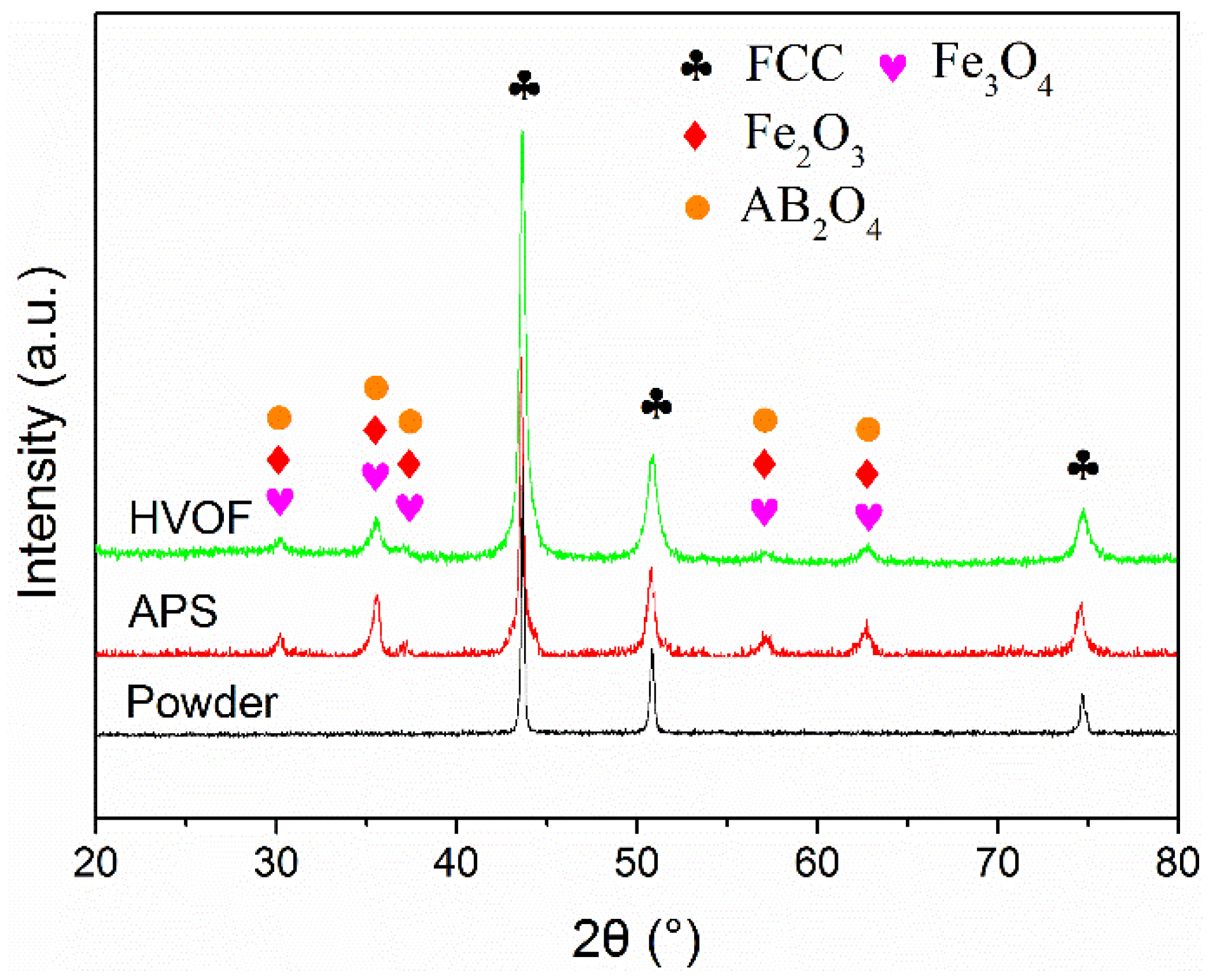
The XRD patterns of the feedstock powders and as-sprayed coatings were illustrated in
Figure 2. It is evident that FeCoCrNiMo0.2 gas-atomized powders exhibit a single typical FCC-structure solid solution phase with diffraction peaks at 2θ = 43.66°, 50.82°, and 74.67° [
18]. According to the empirical rules, solid solutions were generally formed in HEA systems under the following certain conditions. (1) The electron concentration (
VEC) was greater than 8 [
25]; (2) a new parameter combining effects of entropy and enthalpy (Ω) was proposed to be more than 1 and atomic size differences (δ) was less than 6.6% [
26]. The parameters
VEC, Ω, and δ were defined as the following equations, respectively.
where (
VEC)
i is valence electron concentration of the
ith component,
Xi is the mole fraction of the
ith component.
where
Tm is a melting temperature of the system, calculated as an average of melting temperatures of its components. R is the gas constant, 8.314 J/K·mol.
the configurational entropy.
where
ri is the atomic radius of
ith component, and
is the mean atomic radius of all elements.
In the present study, the Ω, δ, and
VEC values for the FeCoCrNiMo0.2 HEA were calculated to be 4.237, 2, and 8.14, respectively, which tallied well with that proposed by the criterion above. Furthermore, the configurational entropy of HEA calculated by Equation (3) was 12.57. According to the Thermodynamic Second Law, the state with lowest Gibbs free energy would be the equilibrium state. As a result, such high configurational entropy is available to enhance the solid solution by means of reducing the Gibbs free energy of formation, especially at high temperature [
27].
The XRD patterns of these as-sprayed coatings indicated that both of the HEA coatings were primarily composed of FCC solid solution with small amount of oxides, including a mixture of Fe
3O
4, Fe
2O
3, and some binary oxides of the chemical formula AB
2O
4 (A = Fe, Co, Ni and B = Fe, Cr). It could be concluded that no obvious phase transformation was identified except for the oxidation of feedstock powers during these thermal spray processes. Previous research proved that high entropy alloys generally exhibited high thermal stablity owing to the high entropy and sluggish diffusion effect. During the thermal spray process, each droplet cools at very high rates (>104 K/s) to form uniform, very fine-grained, polycrystalline coatings. It was apparent that FeCoCrNiMo0.2 gas-atomized powders were subjected to slight oxidation during these thermal spray processes. The results indicated that these oxides were also composed of a mixture of oxide solid solutions. On the basis of entropic effects, the random cation occupancy in spinels was known for oxide system [
28,
29]. According to the relative intensity of the diffraction peaks of oxides, it was concluded that the feedstock powders suffered from a much more seriously oxidation during the APS process. A broadened diffraction peaks in the XRD pattern was observed at 2θ = 43.664° in the HVOF coating, indicating a fine grain structure.
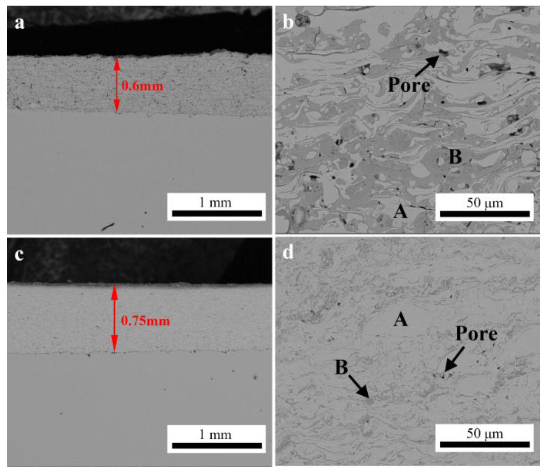
Figure 3 shows the cross-sectional SEM images of the HEA coatings prepared by APS and HVOF, respectively. It could be found that both of these coatings presented a typical lamellar structure with two obviously identifiable contrasts. The EDS analysis results (
Table 3) showed that the grey region was HEA phase (labeled as A) and the dark grey region was dispersed oxide phase (labeled as B). Except for the presence of oxygen, the results indicated that no obvious changes could be detected in the chemical composition between the feedstock powders and the metal phase included in the as-sprayed coatings. The oxides content and porosity of these as-sprayed coatings was calculated and shown in
Table 4. It was obvious that the APS coating has a high concentration of oxides with more microstructure defects, such as pores and inter-splat interfaces, than that in the HVOF coating. In the HVOF process, the flame temperature in the combustion chamber was reported to be up to approximately 3000 °C [
30]. The feedstock powders were heated up to approximately 3000 °C and accelerated to speeds in the range of 200–1000 m/s by the combustion gas in the gun. This gives high acceleration to powder particles which were partially melted and deposited on substrate layer by layer with splat cool mechanism. In contrast, gas heating is sufficient to generate core plasma temperatures exceeding 10,000 °C during the APS process. Therefore, the feedstock powders could be melted completely and were more easily oxidized during the in-flight process than that in HVOF [
30]. As the particles spread on impact, surface oxide films fractured with the flowing metal and become included in the coatings as the oxide stringers. As shown in
Figure 3c,d, pores were commonly distributed in the interface of the metal HEA phase and oxides, indicating that the formation of these microstructure defects, such as interlamellar gaps, porosity, and delamination, was significantly influenced by the oxidation behavior of the in-flight molten droplets. According to the literature [
31], pores can originate by the material shrinkage on cooling from the liquid state, shadowing effect and poor wetting onto adjacent surface of the oxidized droplets.
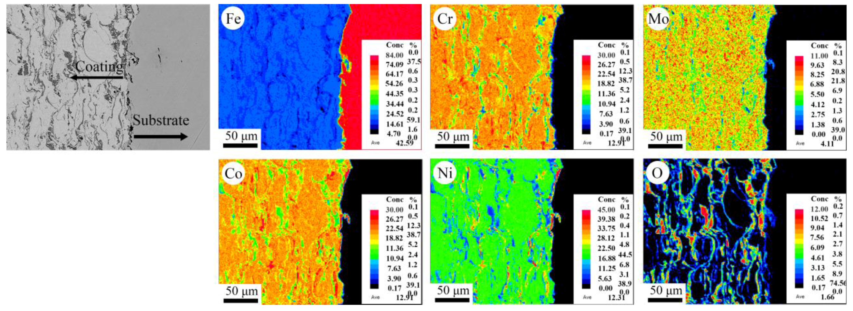
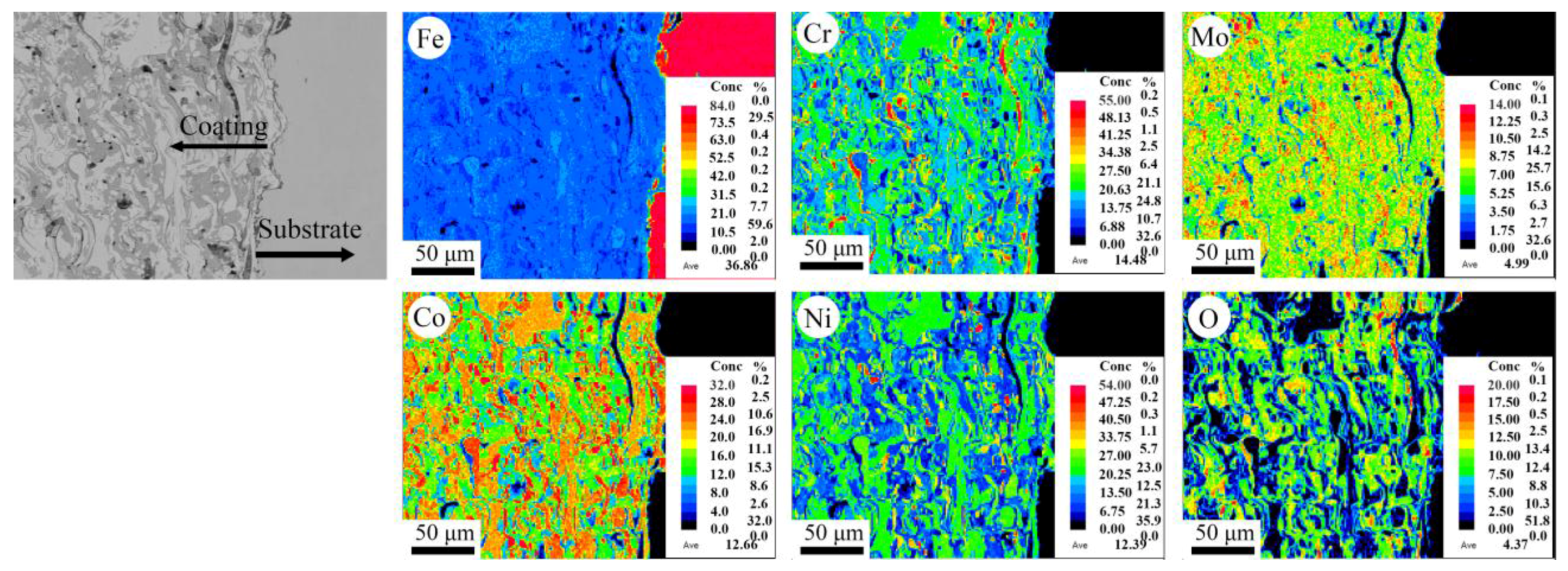
Figure 4 and
Figure 5 show the composition mapping of all the elements in the cross-sectional microstructure of these as-sprayed coatings. The results showed that the Fe, Co, Ni, Cr, and Mo elements were homogeneously distributed and enriched in the metal phase, while the O element is enriched in the grey oxide phase. It could be concluded that these coatings possessed a typical homogeneous microstructure, as reported in most of the traditional metal composite coatings.
3.3. Mechanical Properties
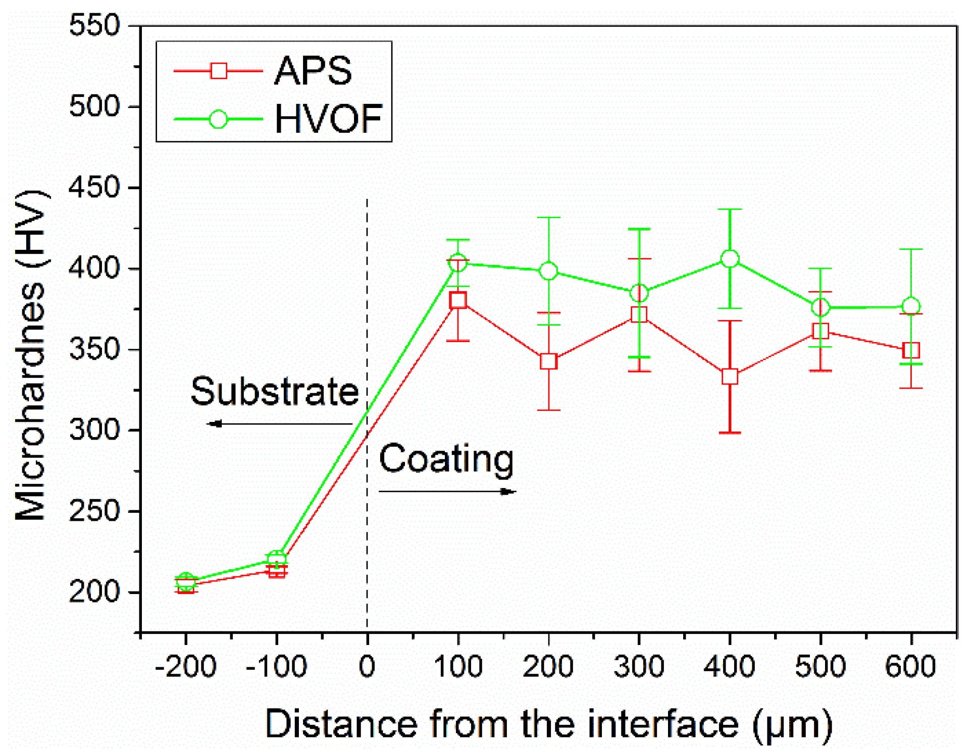
Figure 6 presents the evolution of microhardness values of these as-sprayed coatings as a function of distance from the interface to the surface. The average microhardness values of the APS coating and HVOF coating were measured to be 356 HV
0.2 and 390 HV
0.2, respectively, which were much higher than that of the substrate and the FeCoCrNiMo0.3 bulk alloys (210 HV) [
32]. Furthermore, it could be found that the microhardness values of the APS coating exhibited more drastic fluctuation than that of the HVOF coating. It was mainly ascribed to the heterogeneous microstructure with high content of oxides and defects, such as the pores and interfaces, as shown in
Figure 3. Futhermore, the microhardness of the oxides in the APS coating was also characterized to be as high as 594 HV
0.05. It could be concluded that the microhardness of the APS coating was enhanced by these oxide inclusions. However, the microhardness of thermal sprayed coatings could be generally degraded by the microstructure defects, as widely reported in the literature [
33,
34]. In HVOF spray process, the feedstock powders was heated at a relatively low temperature and accelerated to get an ultra-high velocity [
35,
36]. Therefore, the HVOF coating generally possesses a homogeneous microstructure with low content of oxides and defects, resulting in the comparatively uniform microhardness measurement results.
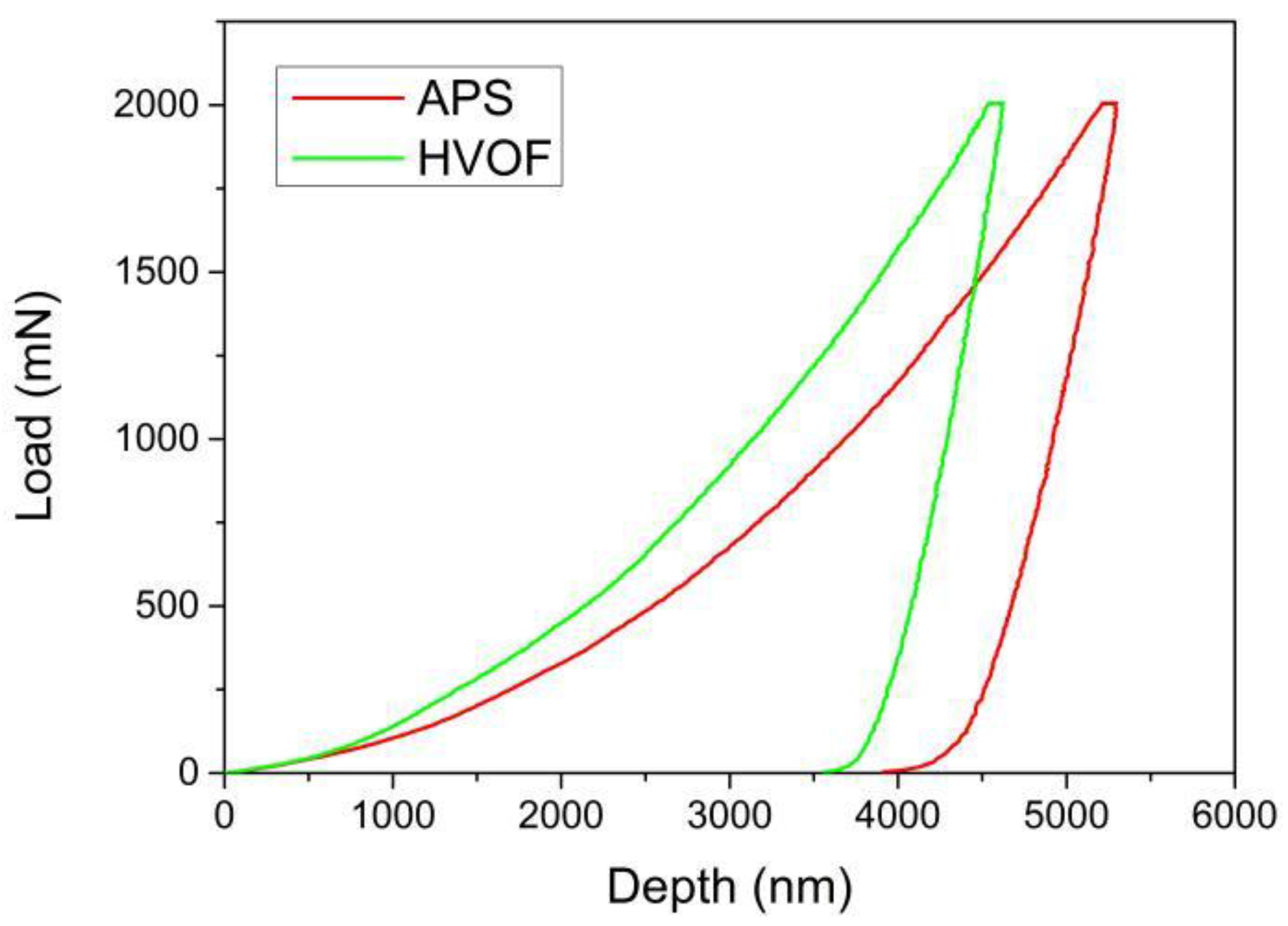
Figure 7 plots the the load-depth curves of these thermal-sprayed coatings. The maximum indention depth
hmax of the HEA coatings sprayed by APS and HVOF are 5.3 μm and 4.6 μm, respectively. The stiffness can be obtained by calculating the initial slope of the curve during unloading and then the value of reduced Young’s modulus can be further deduced [
37]. As listed in
Table 5, the Young’s modulus of these coatings were significantly lower than that of these bulk HEAs, such as 202 GPa for the typical FeCoCrNiMn alloy [
38].
3.4. Tribological Behavior
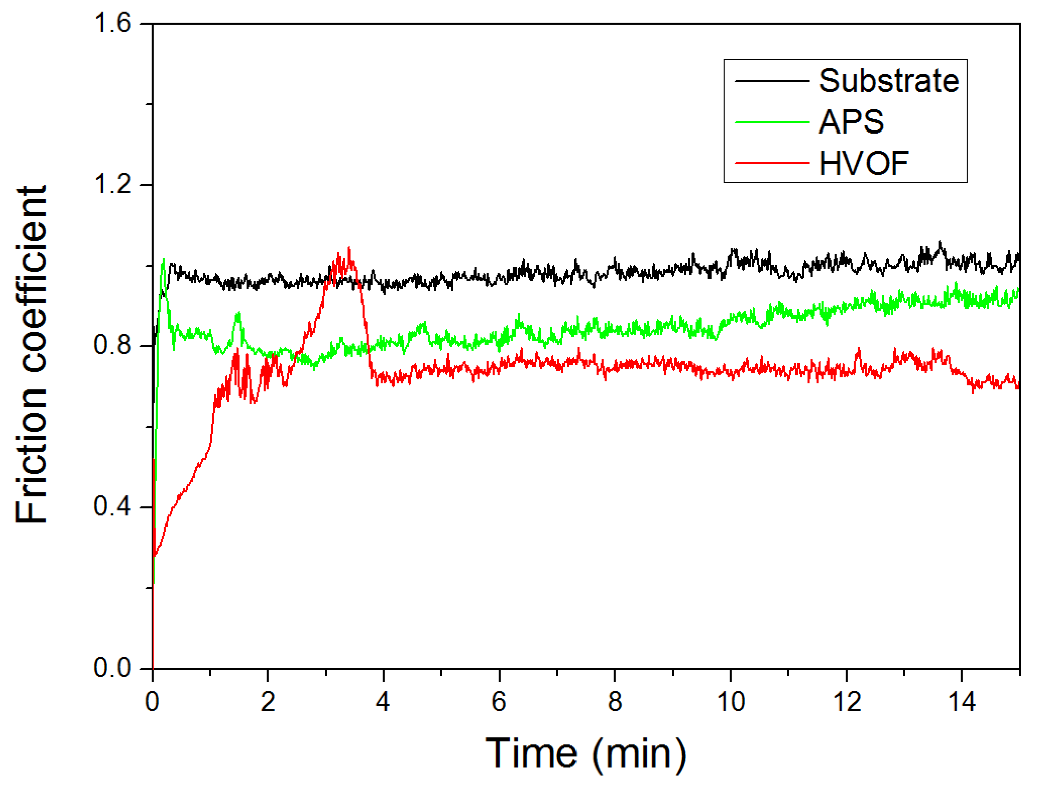
The evolution of friction coefficients of these coatings and the 45# substrate during the reciprocating wear test are displayed in
Figure 8. The average friction coefficient of the HVOF coating and APS coating was approximately 0.75 and 0.84, respectively, which was much lower than 1.0 of the substrate. It can be observed that the friction coefficient curves of these coatings fluctuated up and down in the initial stage, which was mainly ascribed to the variation in the actual contact area and adhesion between the counterpart ball. At the following stage, the friction coefficient curves tend to stabilize at a constant value. It was concluded that the contact area remains almost constant for the rest of the test. Furthermore, it was apparent that the friction curve of the HVOF coating exhibited a drastic fluctuation in the initial stage, which may be indicative of continuous formation and breaking of the transfer layer [
39].
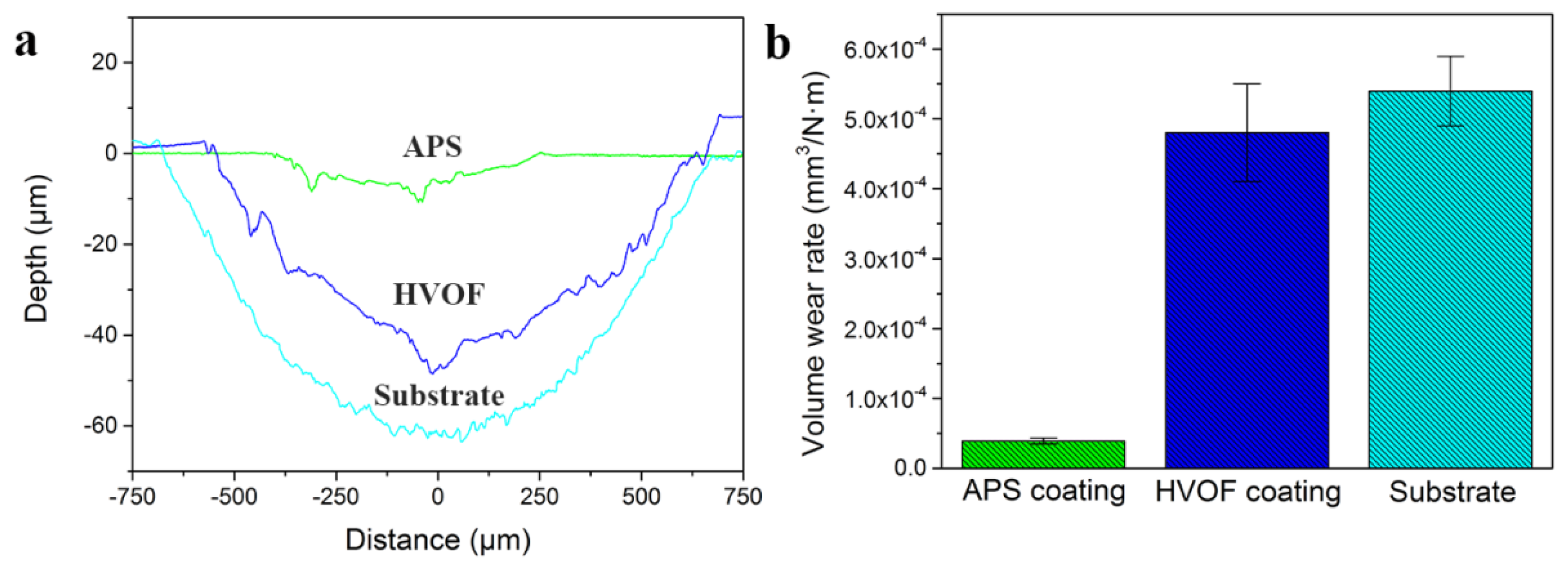
The volume wear rate was calculated to evaluate the wear resistance of these coatings, as shown in
Figure 9. It was observed that the wear rate of the APS coating was approximately 3.9 × 10
−5 mm
3/N·m, which was an order of magnitude lower than the 4.8 × 10
−4 mm
3/N·m of HVOF coating and the 5.4 × 10
−4 mm
3/N·m of the 45# steel substrate. The results indicated that the APS coating possessed the most outstanding wear resistance. Based on the results mentioned above, it could be concluded that the biggest difference between the APS and HVOF coatings was the abundant oxides inclusions and pores in the microstructure. Previous researches reported that these oxides were known as not only the reinforced particles for the enhanced microhardness, but also sometimes as the lubricant for the high wear resistance [
24,
40,
41].
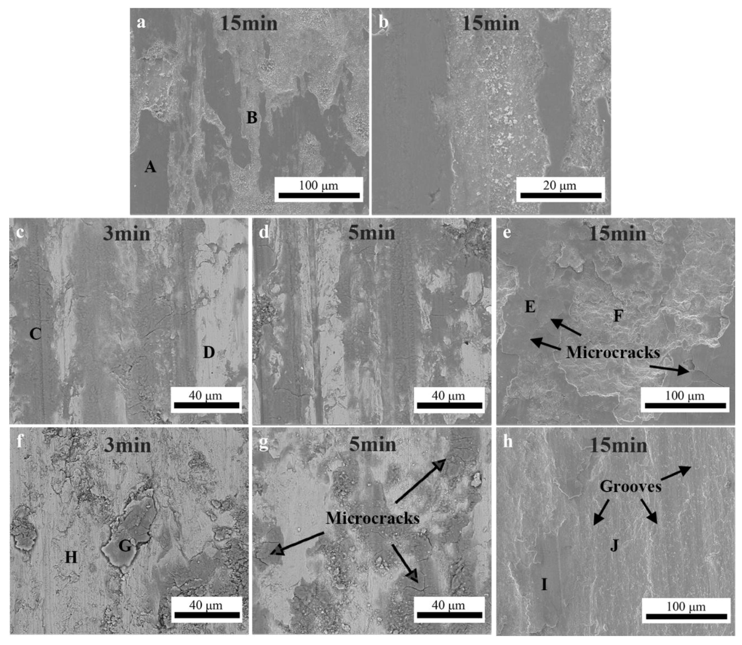
In order to further clarify the wear mechanism, the worn surfaces of HEA coatings and 45# steel substrate are presented in
Figure 10. As shown in
Figure 10a,b, it was apparent that the worn surface of the 45# steel was covered by inconsecutive oxide films referred to in the relatively dark area. The EDS analysis results indicated that the oxide film was mainly composed of iron oxides, as shown in
Table 6. Plenty of wear debris particles could be observed in the worn marks. The oxide scales were peeled off along with the sliding direction of the GCr15 counterpart, indicating that the oxide scales were uncompact and exhibited a poor bonding strength with the substrate. Therefore, we can deduce that the 45# steel suffered from seriously oxidative wear.
Figure 10c–e showed the worn surface morphologies of the APS coating after friction test for 3 min, 5 min, and 15 min, respectively. In the initial stage of the friction test (as shown in
Figure 10c), it was obvious that small amounts of oxides was formed on the worn surface. The oxidation behavior of the APS coating was significantly accelerated as the friction test proceeded. These oxides were trapped in the sliding surface and compacted into a layer called transfer layer, which exhibited a good adhesive strength with the APS coating. This transfer layer prevents the sliding surfaces from direct metal-to-metal contact and consequently inhibits adhesive wear [
42]. As shown in
Figure 10e, a thick oxide layer was formed on the worn surface of the APS coating after friction test for 15 min. This oxide layer underwent continuous stress, which can create damage. The orientation of the microcracks was disordered, revealing that the failure mechanism of the oxide scale was caused by the crack propagation. This compacted oxide layer cracked and flaked off during sliding, resulting in the formation of relatively large-sized wear debris [
43].
Figure 10f–h showed the worn surface of the HVOF coating after friction test for 3 min, 5 min, and 15 min, respectively. As shown in
Figure 10f,g, the worn surface of the HVOF coating also had been oxidized, caused by the frictional heating at the asperities contact. What is different from that on the APS coating is that only small portion of worn surface was covered with oxide layers. A lot of cracks could be observed within the oxide layers. The worn surface was much more uneven with a lot of large sized wear debris, which were proposed as the main reasons for the variation in the actual contact area, resulting in the drastic fluctuation of the friction coefficients in the initial stage of the friction test, as shown in
Figure 8. As the friction test proceeded, ploughed grooves were clearly observed in
Figure 10h. It was concluded that the dominant wear mechanism is mild abrasion and ploughing by plastic deformation.
As discussed above, both of the APS and HVOF coatings showed a superior wear resistance than that of the 45# steel substrate. It was suggested to be mainly attributed to their high hardness and the difference in wear mechanism. According to the classic wear theories, the wear resistance of materials was generally in direct proportion to its hardness or the ratio of hardness and elastic modulus [
44,
45]. It was apparent from
Figure 9 that both of the APS and HVOF coating showed a much higher hardness than that of 45# substrate. Furthermore, the oxide scale formed on the worn surface of the 45# steel was uncompact and exhibited a poor bonding strength with the substrate.
In the present study, the average microhardness of the HEA metal phase and oxides in the APS coating, labeled as A and B in
Figure 4, was measured to be 404 HV
0.05 and 594 HV
0.05, respectively. It was much higher than 332 HV
0.05 and 512 HV
0.05 of that in HVOF coating. However, the average microhardness values of the APS coating was little lower than that of the HVOF coating. It was indicated that the hardness of the APS coating could be degraded by the microstructure defects, such as the pores and the interface between the metal phase and oxide stringers. Similar research results also were reported by Guo et al. and Tian et al. [
46,
47].
Figure 9 indicated that the wear resistance of the APS coating was an order of magnitude higher than that of HVOF coating. It was apparent that the wear resistance properties of the APS and HVOF HEA coatings cannot be predicted according to the classic wear theories. As mentioned above, the excellent wear resistance of the APS coating can be attributed to lubricated effect caused by oxide layers [
48]. However, the oxide layers formed on the worn surface of these HEA coatings could be divided into two parts. One is the oxide inclusions formed during the thermal spraying process, and the other is the oxides formed by the oxidation of the metal phase during the wear test. Previous studies reported that the FeCoNiCr–M HEA alloys exhibited excellent oxidation resistance at high temperature due to the sluggish diffusion [
49,
50]. Furthermore, the oxide film was suggested to have a low rate of thickening and a high resistance to spallation. However, the content of the oxide inclusions of the APS coating, which formed during the spraying process, was calculated to be as high as 47%, much higher than 12.7% of that in the HVOF coating. During sliding wear test, all the oxides could be compacted into an oxide layer by the continuous stress. Due to the abundant oxide inclusions, the transformed oxide layer on the APS coatings could be easier to be formed than that of the HVOF coating, which resulted in the superior wear resistance. Saka et al. [
51] have claimed that a harder substrate is able to hold a thicker transfer oxide layer more firmly as compared to a softer one. Therefore, the oxide layer formed on the metal phase in the APS coating was suggested to be more stable than that on the HVOF coating.


