2. Materials and Methods
2.1. Optical Analysis of the Material
For the ultra-low anti-reflection coating, the optical constants of the deposited substrate and optical films were precisely measured as follows. The substrate (Thermanox Coverslip-174977, Thermo Fisher Scientific Inc., Waltham, MA, USA), which was made of polystyrene and had a diameter of 22 mm and a thickness of 0.2 mm, was ultrasonically cleaned for 15 min and then dried with an air spray gun. The transmittance was measured using a Varian Cary 5E spectrophotometer (Varian, Palo Alto, CA, USA) at wavelengths of 400 nm to 700 nm in the visible spectrum. To measure the precise optical constants of the plastic substrate, the back surface of the plastic substrate was carefully ground and blackened to eliminate its reflection. The polarized light reflected by the front surface in the visible area at three incident angles of 55°, 60°, and 65° was evaluated using a VASE ellipsometer made by J. A. Woollam Co., Inc. (Lincoln, NE, USA). The two coating materials, silicon dioxide and Substance-2 made by Merck, were respectively deposited on two silicon wafer substrates using a vacuum deposition method and their optical constants were also evaluated using the VASE ellipsometer.
2.2. Thin Film Design
In this study, we used the optical admittance method to design the double-layer anti-reflection coating on the plastic substrate. The coating materials for the double layer were silicon dioxide and Substance-2, with a low and a high optical index, denoted by
nL and
nH, respectively. The d
H and d
L are the thicknesses of the
nH layer and
nL layer, respectively. The admittance of the substrate is expressed as
Ys, where
Ys = (
ns −
iks)
Y0, and
Y0 is the admittance of free space. When the reference plane moves from the substrate surface to the input surface of the double layer, the input admittance
Y = C/B can be calculated at the new reference plane by the characteristic matrix expressed as:
where,
δ
H and δ
L are the phase thicknesses of the silicon dioxide and Substance-2 films, respectively. Then, the reflectance
R of the double-layer film on the substrate is calculated by [
3,
4,
5]:
where
Yl (=
nlY0) is the admittance of the liquid immersing the plastic substrate in our study. The value of the reflectance approaches zero if the equivalent admittance
Y equals that of the liquid
Yl. In this case, the double-layer film exactly matches the optical indices of the plastic substrate
ns −
iks and of the liquid
nl 1.34, which is a compound of ethylene glycol and pure water. The index of the liquid is close to the index of the biological material aqueous solution, allowing for strong optical coupling for biomedical applications [
6]. The optical index of the liquid was confirmed by an Abbe refractometer. For the purpose of anti-reflection matching, we then designed a LabVIEW program (version 7.1, National Instruments, TX, USA) to find the correct thickness of the double layer using the graphical technique of the admittance diagram [
3].
2.3. Deposition of the Thin Film
The index of each layer should be precisely determined by the coating process. At first, the substrates were ultrasonically cleaned in pure water for 15 min, dried with an air spray gun, and then put in the substrate holder of an 80 cm diameter vacuum chamber. The required base pressure for evaporation (6.0 × 10⁻⁶ torr) was obtained using a diffusion pumping system. A silicon dioxide film was prepared by thermal evaporation of the silicon monoxide granule from a molybdenum evaporation boat and a Substance-2 film was prepared by E-gun evaporation with argon ion-assisted deposition, to evaluate the optical constants of the two films deposited on the silicon wafer substrates, respectively. The ion voltage and ion current used in the home-made end-Hall ion source were 100 V and 0.5 A, respectively. Moreover, oxygen gas was fed at 70 sccm into the chamber to reach a partial pressure of 2.0 × 10⁻⁴ torr. The deposition rate and the thicknesses of the two films, which were monitored by a quartz monitor during the deposition process, were about 0.1 nm/s and 100 nm, respectively.
Before applying the double layer coating to the plastic substrate, its surface was cleaned using energetic Ar ions produced by the ion source in a vacuum for 10 min. According to the evaluation of the optical constants, the silicon dioxide and Substance-2 films were, in turn, deposited on each surface of the plastic substrates at 71.71 nm and 11.15 nm, respectively, with the abovementioned deposition process.
2.4. Optical Measurements
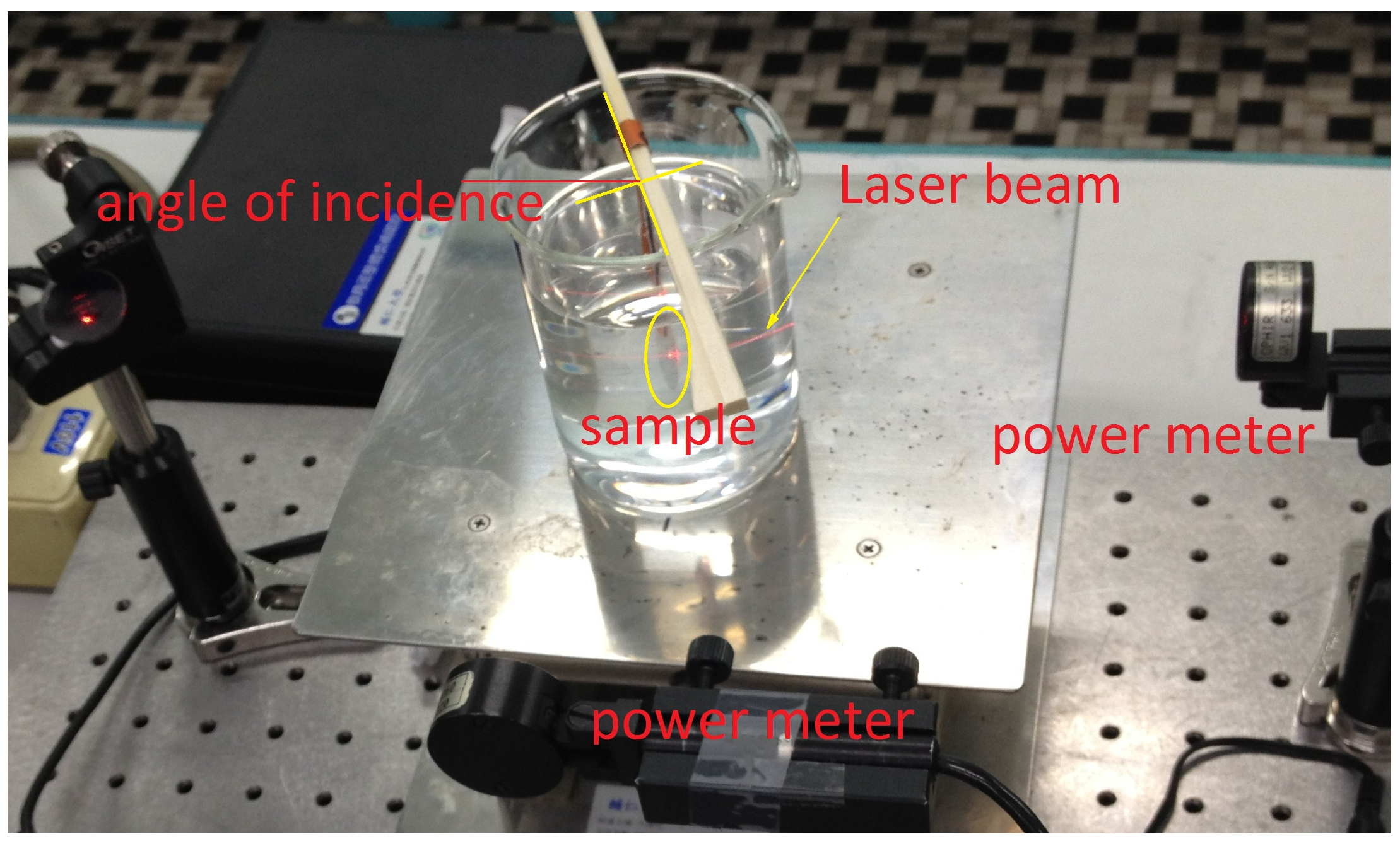
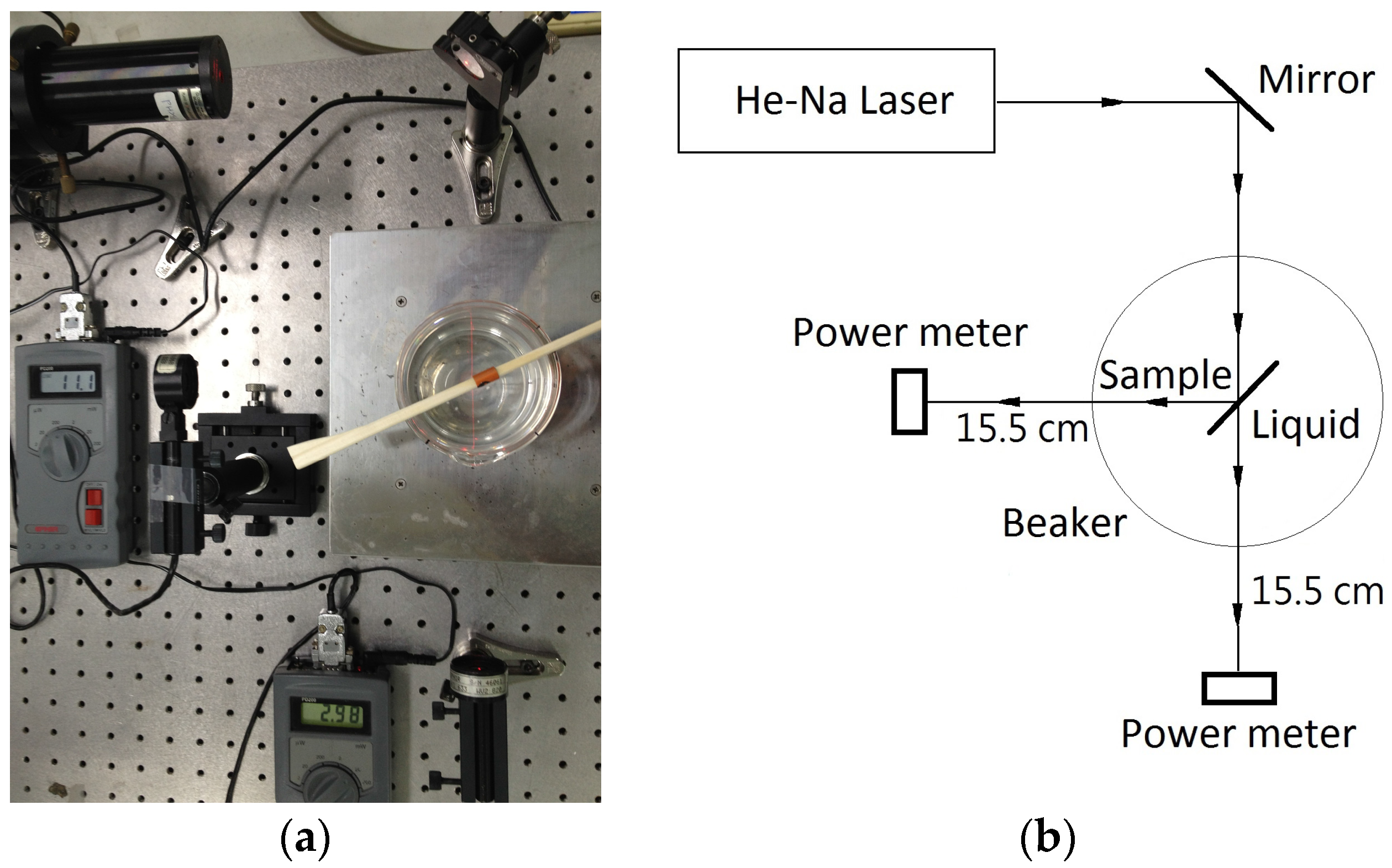
Before measuring the deposited sample while it was immersed in the liquid, the He-Ne beam was adjusted to the center of a beaker that had a diameter of 10 cm and was filled with the liquid. The power of the laser beam was measured by a power meter in a dark laboratory to determine a baseline measurement. The laser beam then illuminated the sample at incident angles of 20° and 45°. The distance between each power meter and the beaker center was 15.5 cm as shown in
Figure 1a,b and
Figure 2. We fine-tuned the power meter positions to measure the maximum values of the transmission and reflection of the laser beams at the incident angles.
3. Results and Discussion
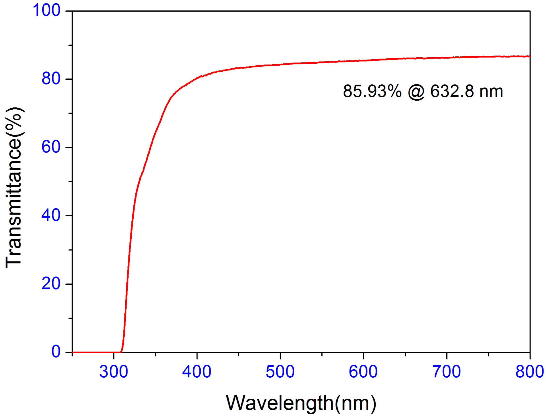
The transmittance of the plastic substrate measured by the spectrophotometer was 85.93% at a wavelength of 632.8 nm, as shown in
Figure 3. We found that the substrate had a higher optical refraction index or optical absorption than those of the B270 or PMMA substrates due to the lower transmittance value. Therefore, we carefully measured its optical constants again using the ellipsometer.
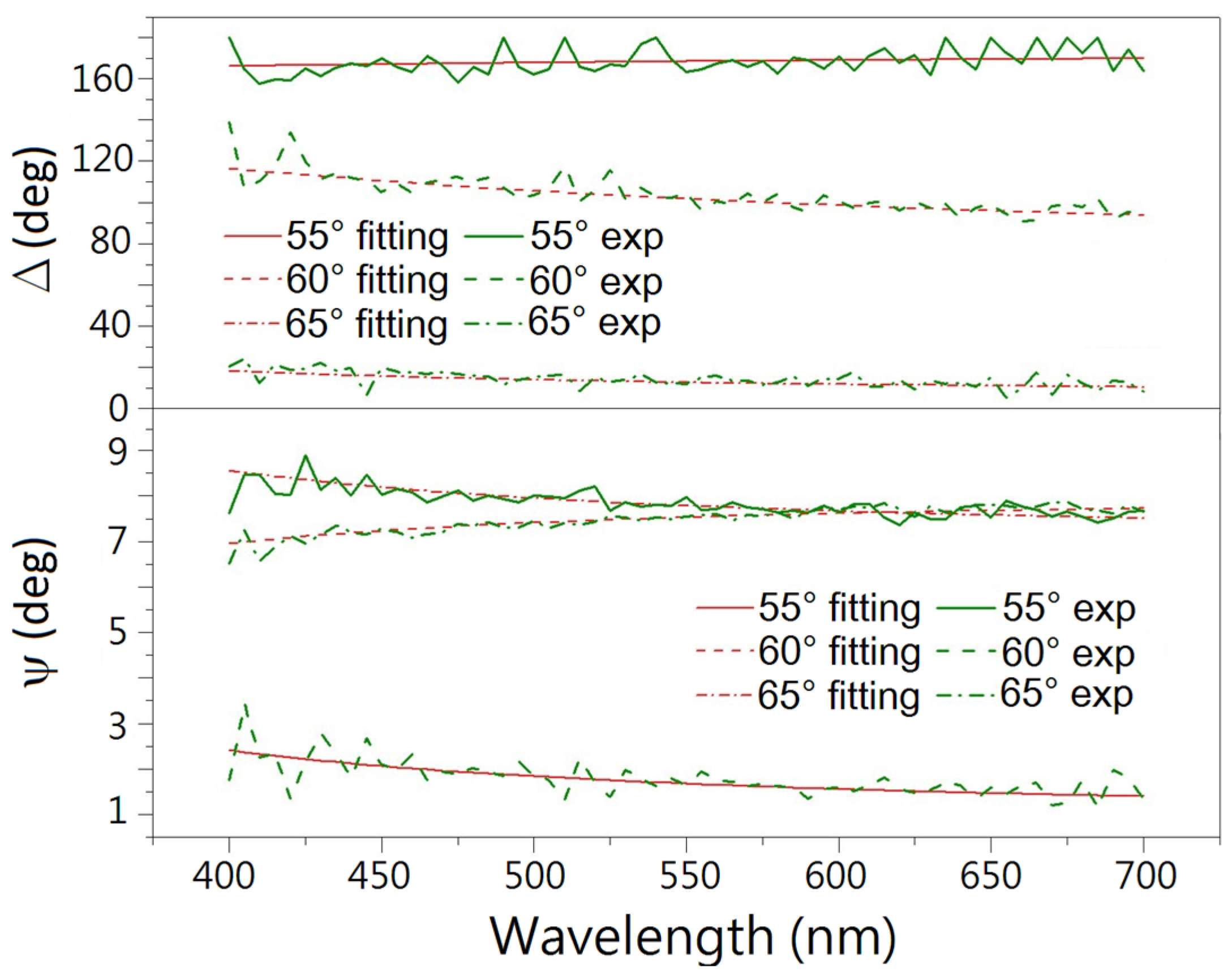
Figure 4 shows the measured ψ and Δ data at the three incident angles of 55°, 60°, and 65°. The experimental values are unstable due to the weak reflection of the transparent surface of the substrate. However, we constructed a Cauchy model for a single material containing only the optical constants. The surface roughness of the plastic substrate can be neglected because it is too small to trap moisture from the air, and therefore will not have an effect on the ellipsometry measurement [
7]. The ψ and Δ data were simulated by the ellipsometry software WVASE32 provided by J. A. Woollam Co. (Lincoln, NE, USA). The mean squared error (MSE) value of the fitted result is only 1.047 [
8], which illustrates that the simulated optical constant of
ns −
iks is reliable due to the small value.
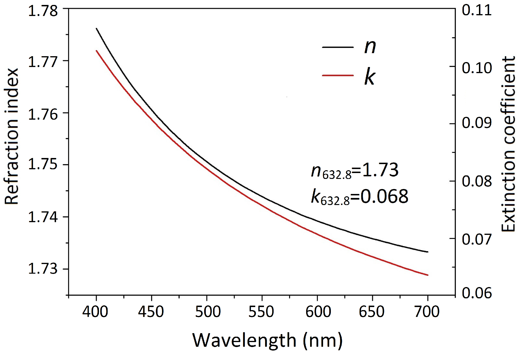
Figure 5 shows the results of the optical index
ns and the extinction coefficient
ks, where
ns is 1.73, and
ks is 0.068 at a wavelength of 632.8 nm.
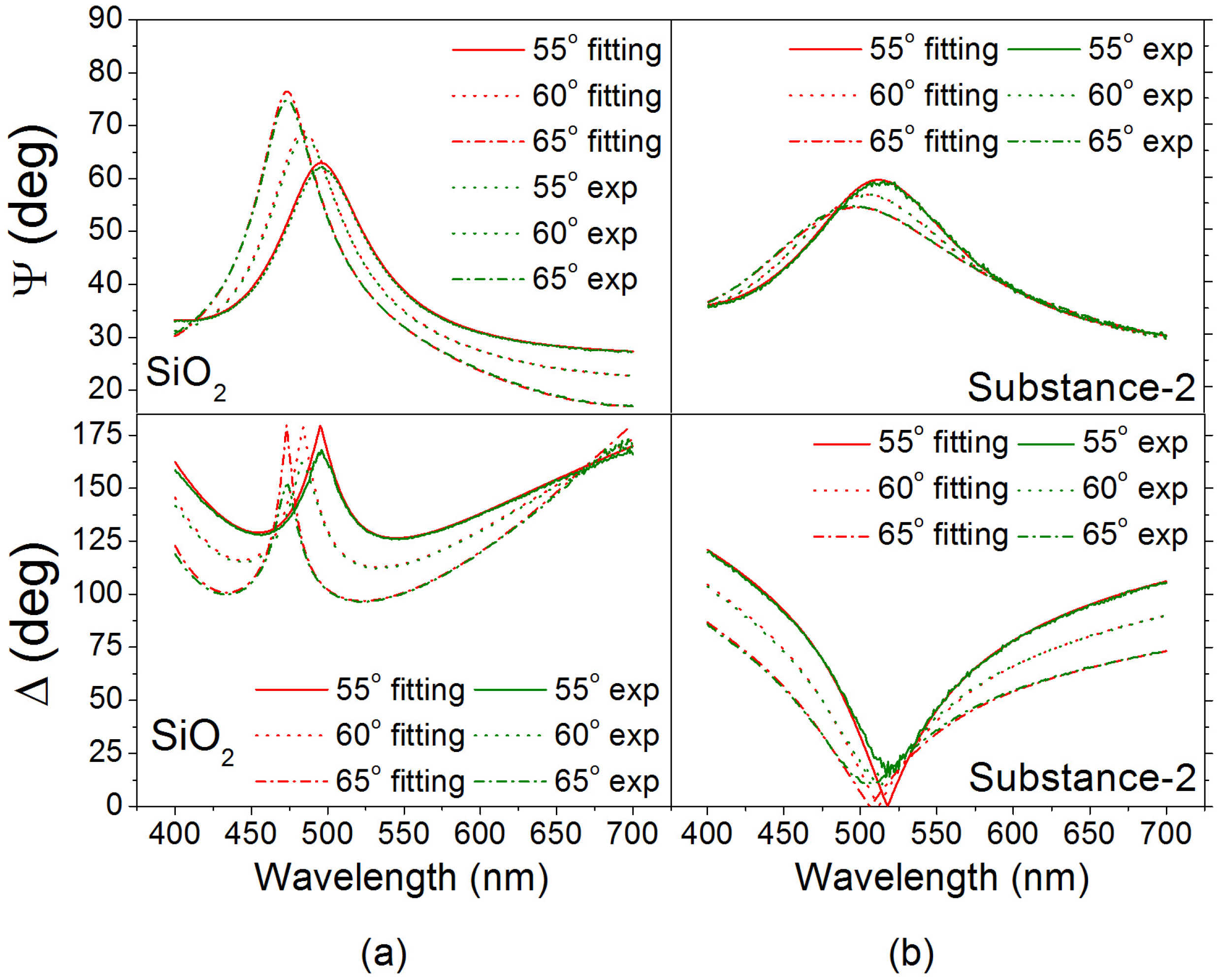
Figure 6a,b shows the measured ψ and Δ data and the simulated results of the silicon dioxide and Substance-2 films on the silicon wafer substrates. We constructed a Cauchy model for a single layer of the film on the substrate, where the surface roughness determined by the substrate was also neglected because the ion assisted deposition during the coating process decreased the boundary scattering and optical absorption, and stabilized the refraction index of the films [
9,
10]. For the measurements of the coating materials, the MSE values of the data fitting results are 2.27 and 2.75, respectively. The two coating materials have a low extinction coefficient
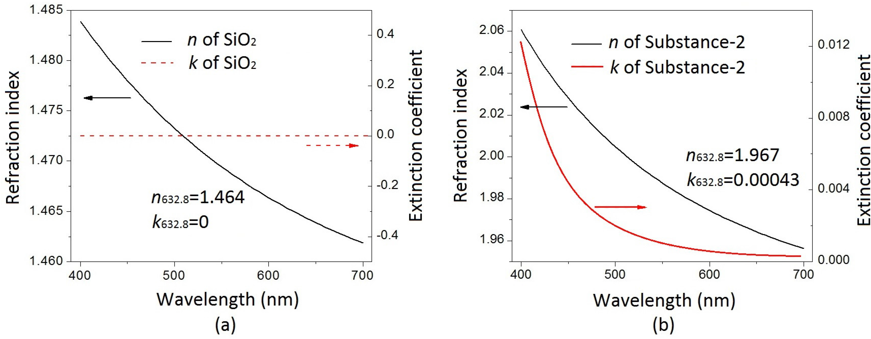
k and a suitable refraction index
n for the plastic substrate, shown in
Figure 7. The silicon dioxide has a low optical index of 1.464 and no optical absorption at a wavelength of 632.8 nm. The other coating material, Substance-2, has a higher optical index of 1.967 and a small extinction coefficient value of 4.3 × 10
−4, as shown in
Figure 7a,b, respectively. It was found that the Substance-2 film deposited under non-heated conditions had a slight absorption due to the lower oxidation of the titanium compound [
11].
Because the deposited substrate is a plastic material that is easily deformed by the heat during the vacuum deposition, the anti-reflection coating requires a smaller thickness and a smaller amount of deposited film. Catalán has expressed that such an anti-reflection coating can only be designed using a double layer [
12]. In this study, we chose silicon dioxide and Substance-2 as the two materials for the double layer. The silicon dioxide was deposited by thermal evaporation with silicon monoxide granules as the starting material [
13], because the evaporation temperature of silicon monoxide, 1200–1600 °C, is lower than that of silicon dioxide, 1800–2200 °C.
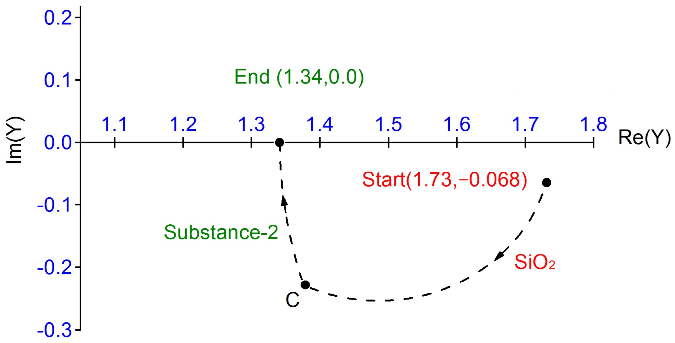
The thickness of the double-layer was designed using the admittance diagram shown in
Figure 8. For the purpose of drawing an admittance diagram, it is convenient to set all optical indices in units of
Y0. Then, the optical admittance will have the same numerical value as the refractive index. From Equation (2)
Y’, (
x +
iy)
Y0, represents the admittance of the double layer at the exit side of the silicon dioxide layer. The equation for the circle of the arc shown in
Figure 8 is:
Its center is at [(
ns2 +
ks2 +
nL2)/2
ns, 0] and it passes through the starting point (
ns, −
iks) in the complex plane. The circle is followed in the clockwise direction from the starting point. The admittance point
C is located when the thickness of the silicon dioxide is increased to the first design thickness of 71.71 nm. This location becomes the starting point of the second circle in the arc, as shown in
Figure 8. The second circle of the deposited Substance-2 film is traced clockwise as the layer successively increases from zero thickness to its designed value. As can be seen from the admittance locus, only the locus passes through the end point (1.34, 0) to obtain zero reflectance; here the thickness of the second designed film is 11.15 nm. The LabVIEW program can easily try to calculate the thickness of each pair of double-layers, which is based on the exact solution referred to in reference [
3]. According to the theoretical calculation above, the equivalent admittance
Y was 1.341 −
i0.000135 and the reflectance approaches 1.6 × 10
−5%. The presence of the double-layer coating produces about zero reflectance at only one wavelength and a low reflectance limited in a narrow region. However, depositing only double layers benefits the plastic substrate due to the low temperature of its softening point. The first layer is thicker than the second layer, which also reduces the heat generation during the deposition process, because the evaporation temperature of silicon monoxide is much lower than that of Substance-2, at 2000–2200 °C.
In our previous study, it was suggested that the plastic substrate be pretreated with plasma before the deposition and that an oxygen-deficient oxide layer, such as SiO
x (where
x is less than and close to 2), be used as a pre-coating layer since the oxygen-deficient oxide tends to chemically bind to plastic substrates [
14,
15]. Kahler et al. have also observed SiO
x (1 <
x < 2) layers with adjustable oxygen content by thermal evaporation of silicon monoxide in a controlled oxygen atmosphere. The chemical disorder in the matrix for SiO
x is higher than that in a pure silicon dioxide film [
13,
16]. In our study, an amorphous film with a small oxygen deficiency was, therefore, pre-deposited on the plasma-pretreated substrate at a low deposition rate with ion-assisted deposition in a non-heated process. These enhance the adhesion of the boundary between the first deposited film and the plastic substrate. Moreover, the evaporation temperature of the second layer Substance-2 is much lower than that of the other metal-oxide coating materials that have a high refraction index. The options described above are the best choice for the plastic substrate coatings. Finally, the ultra-low anti-reflection coating was designed and deposited on the sample, as shown in
Figure 9, to eliminate the laser-beam reflection from the two surfaces.
Table 1 and
Table 2 respectively show the transmission and reflection powers of the laser beam at the incident angles of 20° and 45° for ten as-deposited samples immersed in a liquid with a refraction index of 1.34. The transmittance and reflectance at a wavelength of 632.8 nm then are calculated with the baseline power of 3.08 mW. We cannot measure the value at the normal incidence because of the layout of the measurement instruments. The average power of the transmission and the reflectance at a 20° angle of incidence are 2.961 mW and 1.552 µW; those at 45° are 2.936 mW and 11.16 µW, respectively. The transmittance and reflectance can be calculated by dividing the baseline values. Although the double-layer anti-reflection coating presents zero reflectance at only one wavelength and a low reflectance limit in only a narrow region, the average transmittances of the two incident angles are 96.13% and 95.32%; and the average reflectances are only 0.050% and 0.362%, respectively. As can be seen from
Figure 1, the blurred red light passes through the round beaker due to the light scattering of the liquid. At incident angles of 20° and 45°, the sum of the light scattering and the light absorption of the liquid are 3.813% and 4.31%, respectively, and can be evaluated by subtracting the transmittance and reflectance. The reflectance increases as the angle of incidence increases due to the decrease in the phase thickness of each layer in the double layer [
3]. At the same time, the minimum reflection spectral position is shifted to less than 632.8 nm. It is presumed that the reflectance at a normal incidence will be less than 0.050%. After the optical evaluation of the ten samples in the liquid, the double layers on the surfaces remain intact. Furthermore, the standard deviations of the reflectance of 0.050% and 0.362% shown in
Table 1 and
Table 2, are only 0.0023% and 0.0012%, respectively. This indicates that the double-layer sample immersed in the liquid has very good optical stability. It is possible to speculate that the ion-assisted deposition in the deposition process solidifies the deposited film so that the moisture or water in the environment hardly penetrates the film and changes its refractive index [
10,
17].
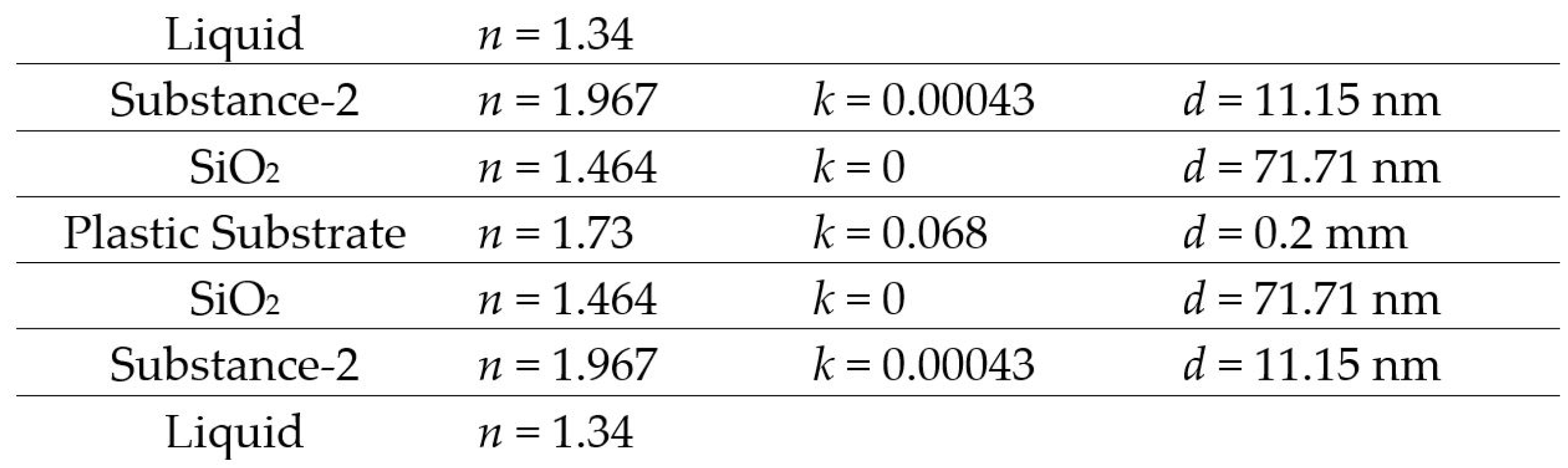
In this study, the two surfaces are designed to be in contact with liquid with refractive index of 1.43. The double-layer film design includes a low refractive index layer and then a high refractive index layer. If the upper surface is exposed to air, the admittance of the input surface should be designed to a value of one. In this case, the first layer may be designed using Substance-2 with a high refraction index; and the second may be silicon dioxide with a low refraction index for the double-layer anti-reflection coating, using the above-mentioned method of the admittance diagram. Moreover, we can pre-deposit a SiO
x layer of several nanometers for the anti-reflection coating of the plastic substrate to enhance the adherence of the double layer [
18].
As noted in the description of the experimental method above, the sample immured in the liquid is not conveniently measured by a conventional spectrometer. However, the theoretical reflectance of the two surfaces in the air without optical absorption of the substrate is 4.135% at a wavelength of 632.8 nm because the equivalent refractive index of each deposited double-layer surface is 1.34 [
3]. Our other experiment in the air measured the reflectivity of about 4.223%. The low reflectance of the sample in the liquid can also be approximately evaluated. However, the standard mean square error is 0.145%, which is larger than 0.050% of the ultra-low reflectance measured in the liquid in the abovementioned experiment.


