1. Introduction
Pneumatic atomizers are widely used in painting industries, especially in the automotive industry. For instance, they are used in the coating of the engine compartment and for spray coating using metallic paints, where a special appearance and high optical quality are required. Numerical simulation as an effective tool plays an important role for planning and optimizing in spray painting processes.
With the help of numerical simulations, it is currently possible to model the complete air flow field between the nozzle of an atomizer and the target [
1]. Some experimental and numerical studies [
2,
3,
4,
5,
6,
7,
8] of air and air-assisted spray guns have been carried out in recent years, focusing mainly on the characterization of droplet size distribution, on the effects of air flow and on the particle trajectory. However, modeling of the spray painting process using pneumatic atomizers—especially modeling the droplet phase—is still quite difficult: The mechanism of liquid atomization is quite complicated. There is no physical model that can be used to predict the atomization process, although currently more and more numerical studies [
9,
10,
11] on air-assisted primary break-up processes have been performed by means of direct numerical (DNS) and large-eddy simulation (LES). Furthermore, for instance, it is difficult to perform measurements of the droplet size distribution close to the atomizer nozzle by using optical methods, because of the high velocities and the high number density of droplets.
Experimental and numerical investigations on the spray characteristics of a pneumatic atomizer have been carried out by Domnick et al. [
2,
3]. Basically, they measured details of the spray structure at a 100 mm distance below the spray nozzle by using Phase-Doppler Anemometry (PDA) (Dantec). An elliptical spray region with a 220 mm long axis and an 80 mm short axis was obtained. Altogether, approximately 100 measuring points were taken in a quadrant of the spray region. These spray measurements were used to perform first numerical simulations of the coating process. However, PDA measurements are complicated and therefore time consuming when important atomizer parameters (e.g., atomizing and shaping air flow rate) are changed. This finally limits the practical relevance and applicability of the simulations. Another limitation is that PDA could not be applied to paints that have non-homogeneous optical properties.
In our previous study [
1], the spray behavior of a coaxial jet-type pneumatic atomizer was numerically modeled by means of a commercial Computational Fluid Dynamics (CFD) code. The air flow field between the nozzle and the target was calculated applying the known air inlet conditions directly at the atomizer. The measured integral droplet size distribution obtained at 50 mm distance below the spray nozzle was used for trajectory simulations, assuming that it is also valid close to the nozzle. The initial droplet velocity close to the nozzle was fitted by using measured downstream droplet velocity and film thickness pattern on the target. This way, the two-way coupling process between droplets and air flow—which alters the spray cone shape—can also be taken into account. A similar approach [
8] to creating initial conditions for droplet injection has been used in the CFD simulation of paint deposition using an air spray gun. There too, the droplets were injected quite close to the nozzle and the initial velocity was assumed to be that of the liquid jet at the moment of breakage. The flow field of the continuous phase was extensively analyzed and compared with PDA-measurements. Film thickness distributions on targets have been predicted. However, there was no validation between simulated and measured film thickness distribution.
In this paper, more detailed numerical investigations—namely, sensitivity studies considering different operating conditions and complicated target geometries—are presented. Measured and calculated film thicknesses on the targets are compared to each other. A good agreement between coating experiment and simulation has been found.
2. Experimental Investigation
2.1. Geometry of the Pneumatic Atomizer
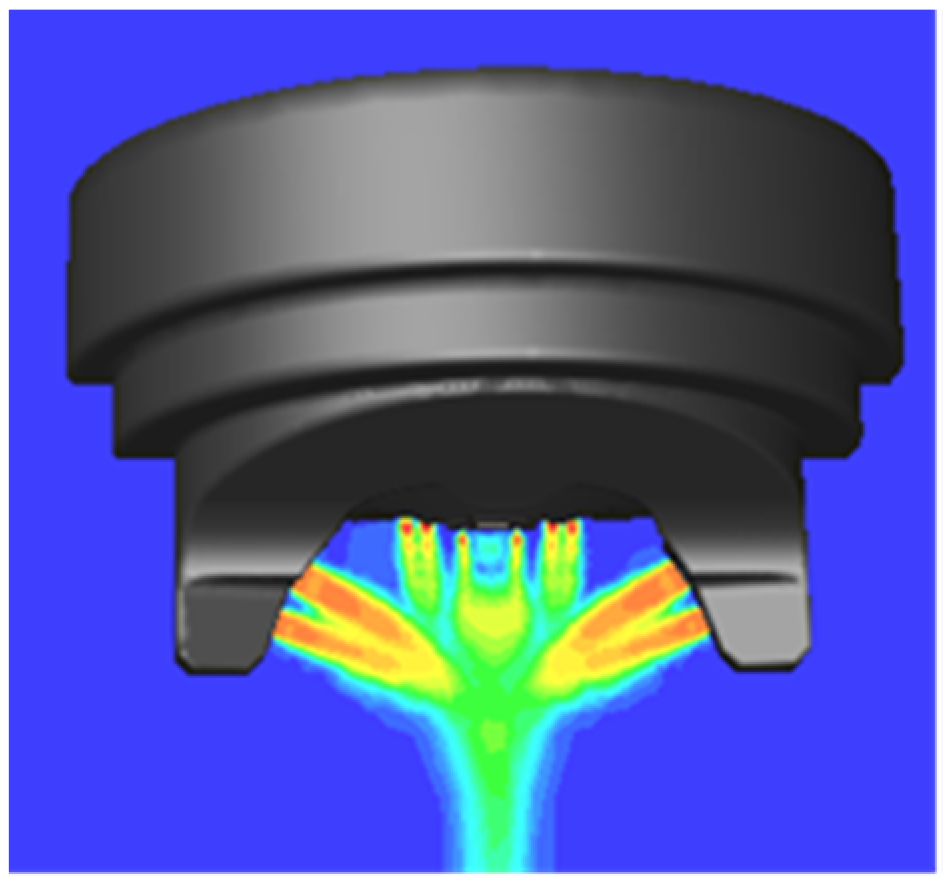
The basic geometry of the pneumatic atomizer used in this study is shown in
Figure 1. Atomization occurs by a coaxial jet arrangement, in which the central paint jet with diameter 1.4 mm (not shown in the figure) is surrounded by high-speed air, leaving the annular ring around the paint nozzle under supersonic conditions. Around the annular ring, there are eight small holes with 0.6 mm diameter, from which the high-speed air is supplied. Four of them are not coaxial, but are oriented at an angle of 45° to the spray axis. In addition, the so-called shaping air nozzles with 2 mm diameter on the two sides of the center jet are used to deform the spray cone for painting larger work pieces.
2.2. Droplet Size Measurements
As already mentioned in the introduction, the CFD model is not able to simulate the atomization process, and thus requires the measured droplet size distribution as necessary prerequisites for the droplet trajectory calculation. In the current study, the atomization characteristics were measured at locations 50 mm below the liquid nozzle using a Spraytec Fraunhofer type particle sizer, which can measure in a 560 µm size range with a f = 300 mm receiving lens. The measuring volume of the laser beam has a diameter of 9 mm.
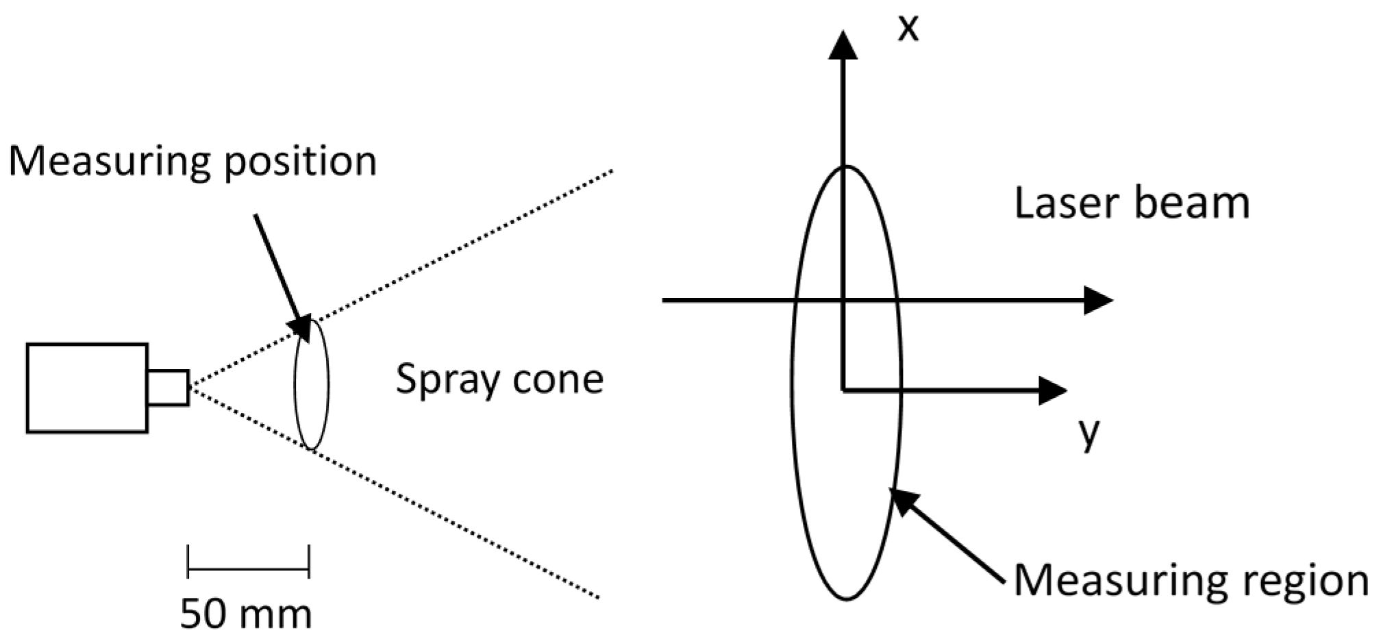
The major characteristics of the atomizer and the operating conditions investigated are summarized in
Table 1. Owing to the shaping air from the atomizer, an elliptical spray cone is formed downstream the atomizer. Size distributions along the long axis of the spray were obtained by moving the atomizer along the
x-direction, as shown in
Figure 2.
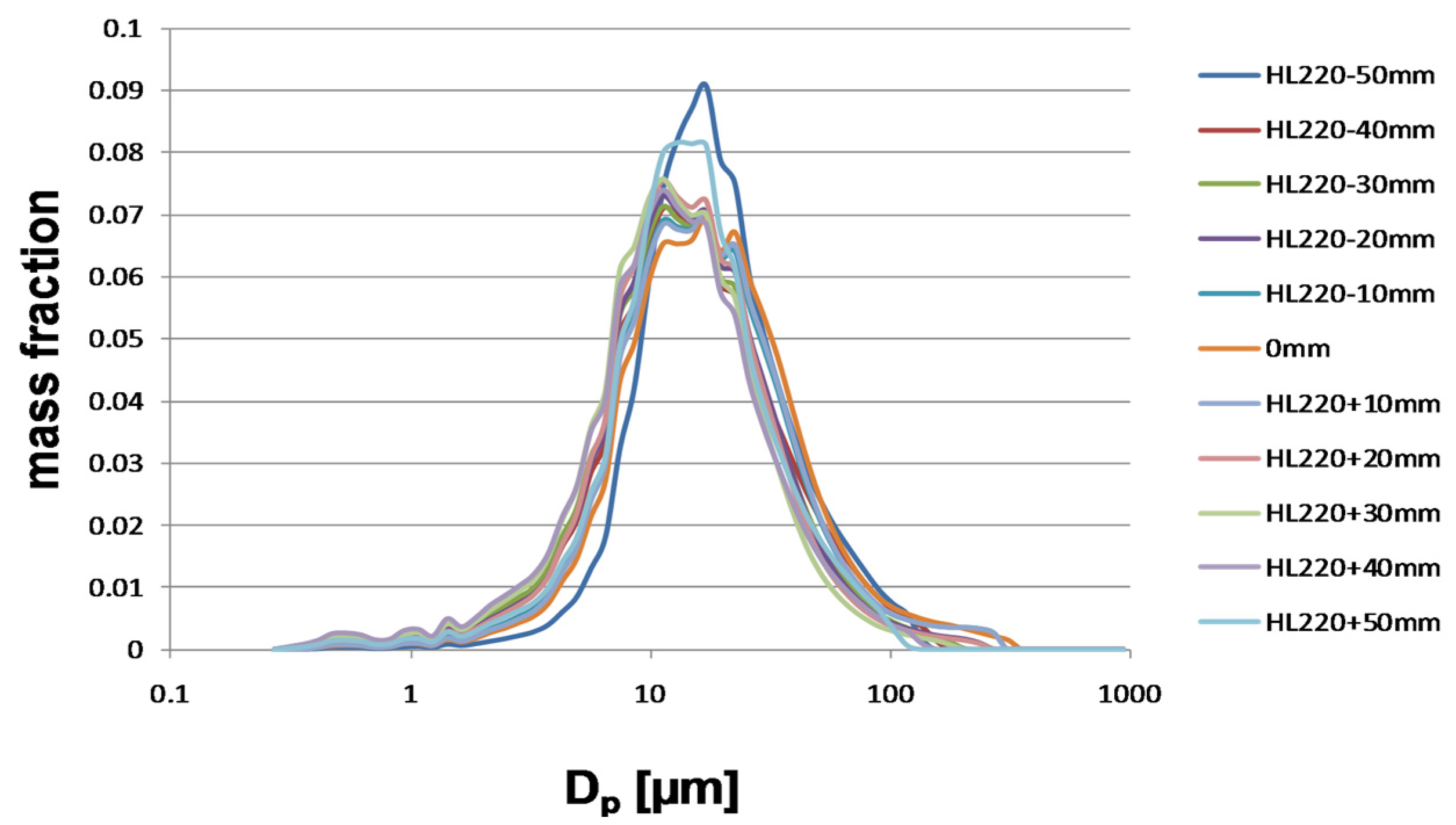
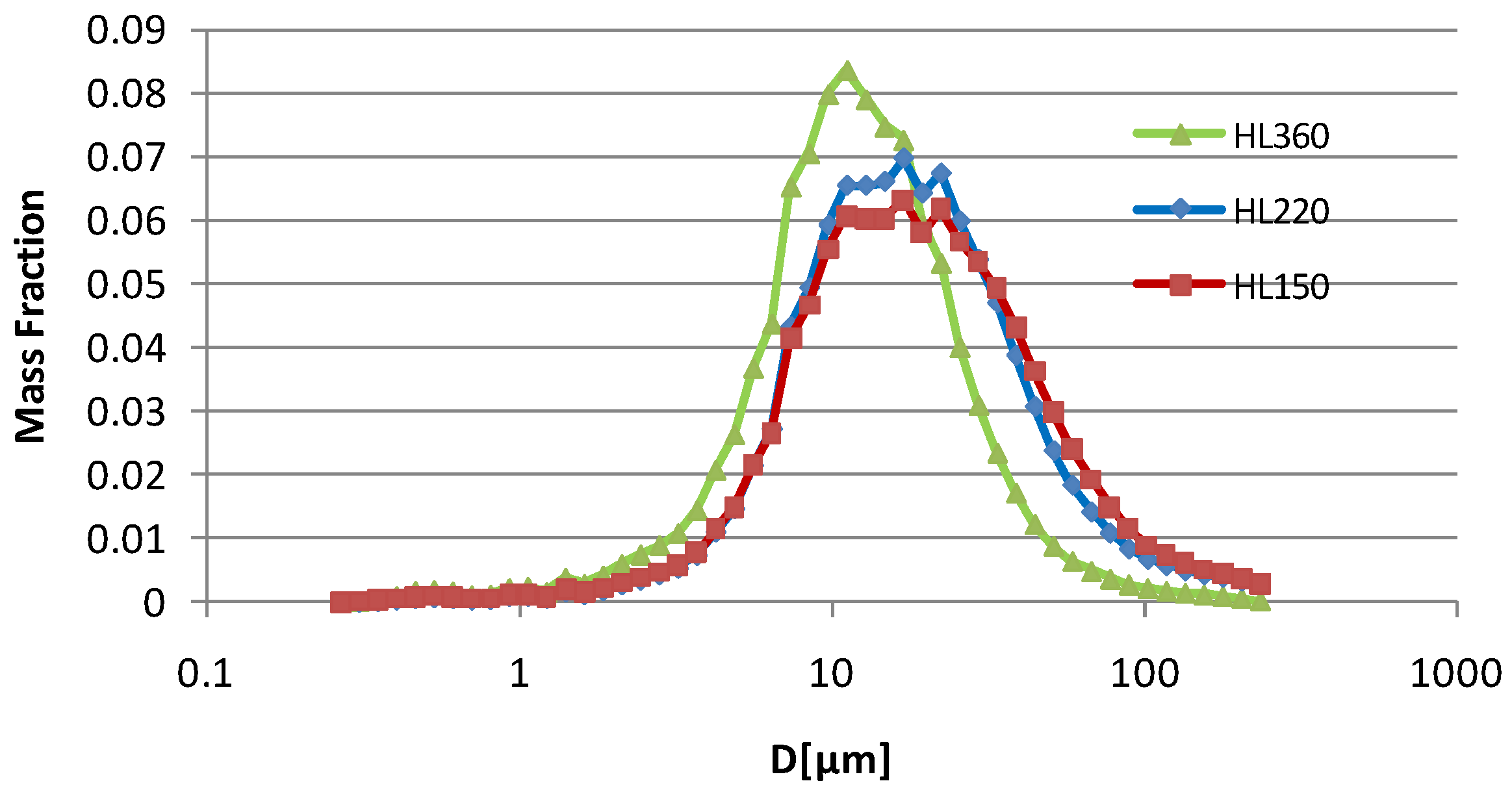
Figure 3 shows the individual droplet size distributions in the elliptical spray region; for instance, for the shaping air flow rate of 220 L/min. The integral distribution of the whole spray region was then calculated based on the individual droplet size distributions and the measured particle concentration in the measuring volume.
Figure 4 shows integral droplet size distributions for each shaping air flow rate. It can be seen that a finer droplet size distribution is obtained by increasing the shaping air flow rate, which means that the atomization process is also affected by the shaping air flow. The experimental results provide important information for the particle injection model in the following numerical simulations.
2.3. Measurement of Paint Film Thickness on the Target Plate
Dynamic spray painting with a relative speed between gun and target of 0.15 m/s and a gun-to-target distance of 250 mm was performed. The target—a flat steel panel with a size of 200 × 800 mm
2—was positioned horizontally. The gun axis was perpendicular to the target surface so that the major axis of the spray pattern was formed along the 800 mm direction. After painting, the panel was put horizontally into an oven for baking. The dry film thickness on the panel was then measured by means of magneto-inductive method.
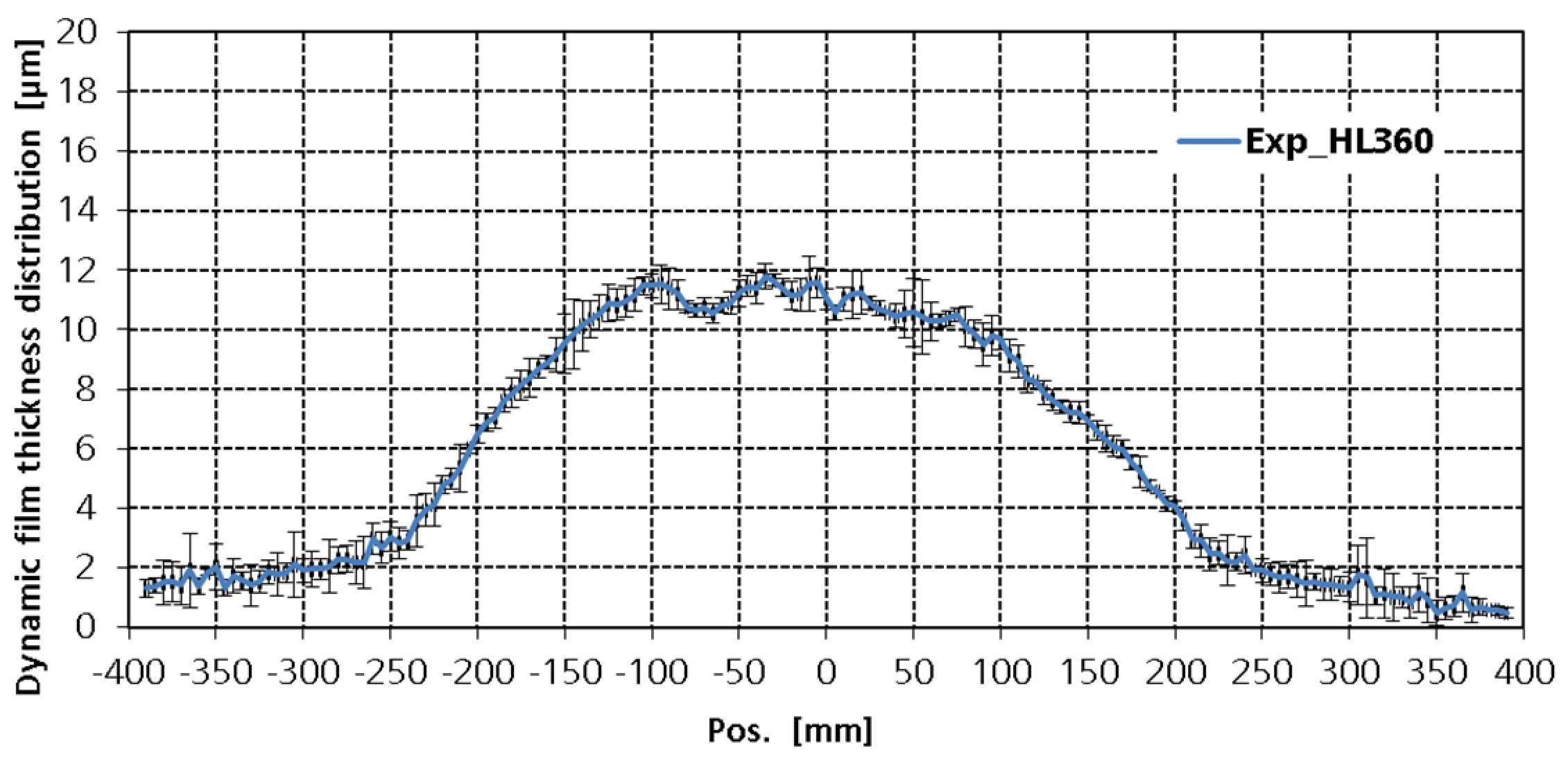
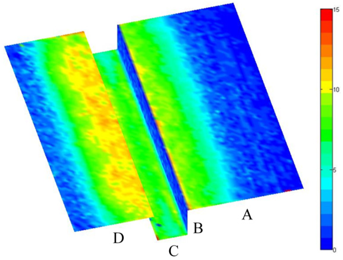
Figure 5 shows the mean values of the measured film thickness distribution with uncertainty bars (standard deviation) for a typical shaping air flow rate of 360 L/min. Spray painting was later also carried out on a more complicated substrate, a 3D-target that consists of four panels. The atomizer was located at the center directly above panel C, moving along the channel. The corresponding film thickness distributions on different panels are shown in
Figure 6. The measured film thickness distributions were applied to compare with the simulation results that will be shown in the next section.
3. Computational Method
The commercial CFD code ANSYS-Fluent 12.0.16—based on the finite-volume approach—was used for the numerical simulations. The gas phase was modeled using the Eulerian conservation equations of mass, momentum, and energy. The 3-D compressible airflow was directly simulated from the nozzle using the coupled solver, as it was found to be more stable than the segregated solver for this specific airflow calculation. As inlet boundary conditions, air mass flow rate and stagnation temperature were used at the air nozzles. Turbulent transport was modeled using the Realizable k-ε model with scalable standard wall function. An unstructured mesh with 1.8 million cells was used to discretize the computational domain of 600 × 2000 × 2000 mm³, and mesh refinement was carried out.
Droplet trajectories were calculated using the Lagrangian tracking method by integration of the equation of motion,
in which the drag force
fD(
u−
up) and the gravity force
FG (force/unit particle mass) were taken into account. Other forces, such as “virtual mass” and Saffman’s lift force may be neglected, since the density ratio between air and liquid is 1 to 1000, and the mean droplet diameter is about 40 μm in current painting processes. In the above equation,
up is the particle velocity and
u the instantaneous air velocity that was calculated by superimposing the local mean velocity and a fluctuating velocity component corresponding to the local turbulence level, using a stochastic tracking model. The effect of the turbulence dispersion on the droplet motion was thereby taken into account with an integral time scale constant of 0.3. In the current study, the interaction between droplets was neglected due to the low mass flow rate of the liquid. Computational particles—namely droplet parcels, representing a number of real droplets with the same properties—were used. The number of computational particles plays an important role in the Lagrangian tracking method. However, in order to save computation resources, 50,000 particles were used per trajectory calculation, which proved to be sufficiently accurate for current industry applications.
In order to carry out the particle trajectory calculation, initial conditions of droplet trajectory must be determined. A method similar to that in our previous study [
1] was applied in the present study. Basically, the droplet injection data was applied in a circular region with a radius of 1 mm, below the liquid nozzle and above the cross-section of the shaping air flow jets, where the axial velocity dominates the air flow field. The integral distributions shown in
Figure 4 were used as droplet size distributions. The droplets are uniformly distributed in the injection region. Nowadays there are more and more numerical studies available on the primary break-up of the liquid based on the Volume-of-Fluid method using different atomizers [
9,
11,
12]. The velocity of shot liquid filaments based on the atomization study [
12] using a coaxial jet atomizer was analyzed, which delivers useful information for the determination of the droplet initial velocity. In the present study, the axial and radial velocity of the droplets were fitted by using the information from the gas flow field and by matching the film thickness distribution on a flat plate. The droplet initial velocity was obtained from the local air velocity with a reduction factor in the order of 0.2–0.7, depending on the shaping air flow rate. The resulting injection data were used not only for spray coating on the flat plate, but also on a complicated three-dimensional work piece, as well as for the case of an inclined atomizer. The simulation results are discussed in the following section.
Static film thickness distribution—namely, the film growth rate (µm/s) on the target—can be obtained after particle trajectory calculation, assuming uniform distribution of droplet mass in a computational cell. Since the spray gun is static in the present numerical simulation, in order to compare with the measured dynamic film thickness distribution (as shown in
Figure 5), integration of the simulated static film pattern has to be carried out [
13], taking into consideration the robot velocity and the wet and dry density of the paint material.
4. Simulation Results
4.1. Spray Painting Calculation by Using a Flat Plate
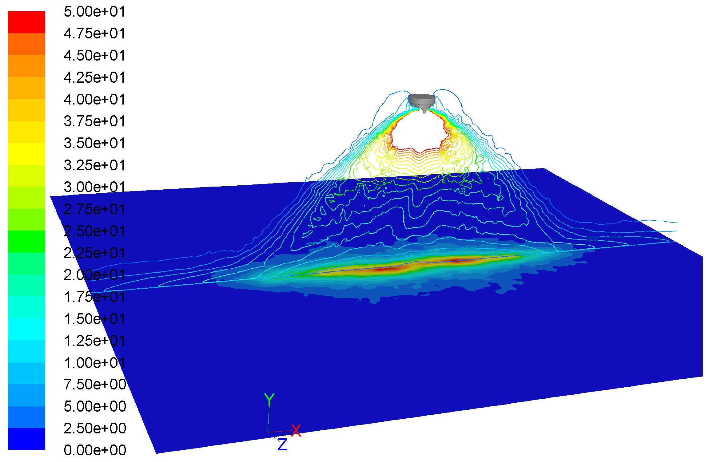
The calculated velocity contours of the airflow field in the plane
z = 0 are shown in
Figure 7. A supersonic velocity (about 545 m/s) is located at the atomizing air nozzle exits. To provide a sensible resolution of the entire flow field, the velocity contours are depicted in the range of 0–50 m/s. Air velocity close to the liquid nozzle and above the cross-section of shaping air jets is about 360 m/s, where computational droplets are injected with the maximum axial velocity of 72 m/s. The corresponding reducing factor for the initial droplet axial velocity is about 0.2 for the case of the shaping air flow rate of 360 L/min. Due to the shaping air, the gas flow field is deformed, deviating from the standard symmetric free jet of coaxial jet atomizers. Here, a quite narrow elliptic flow region is formed with a narrow extension along
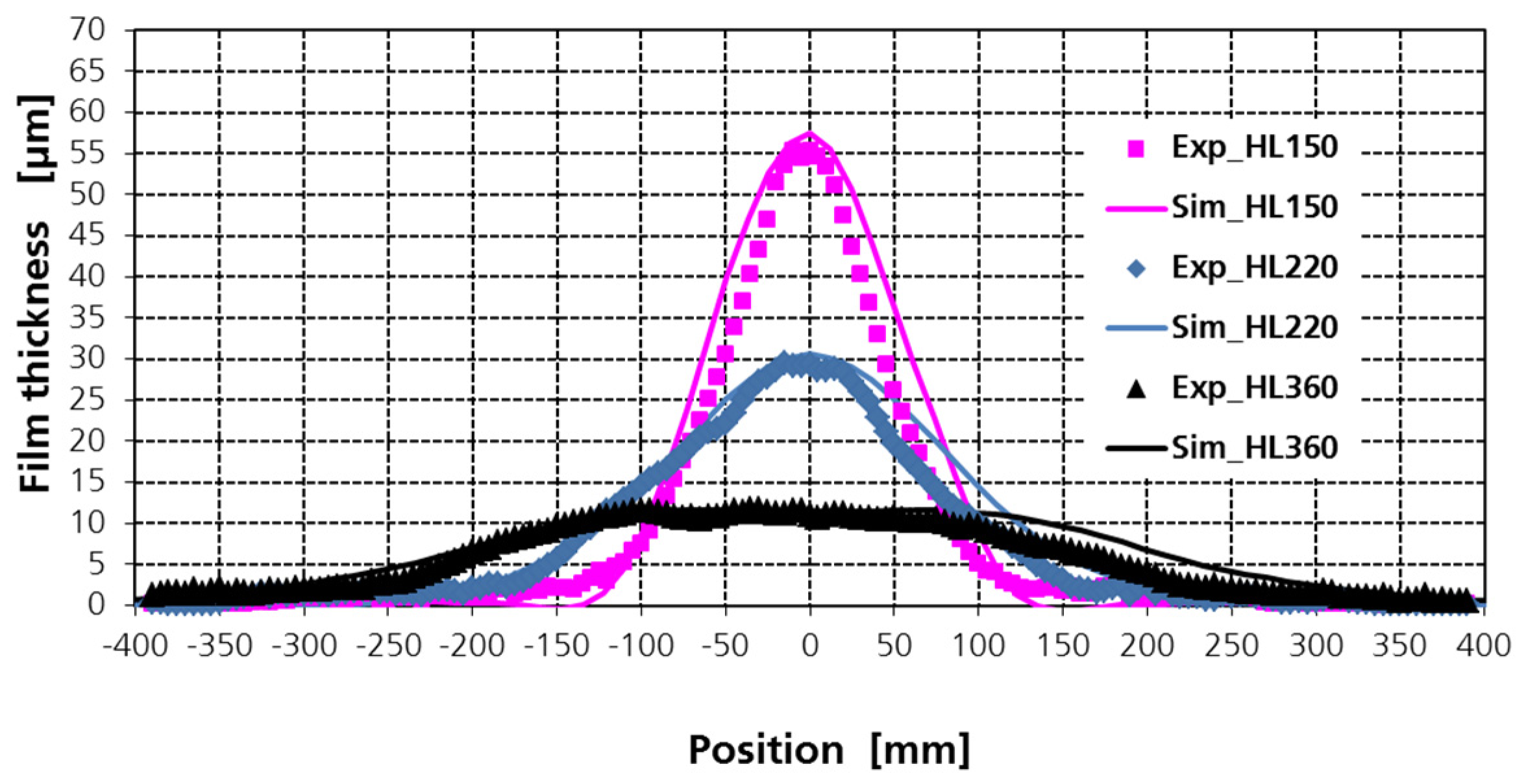
z, which results in a narrow film pattern on the plate (the so-called static film thickness distribution or static film growth rate (µm/s), since the spray gun is static in the simulation). With decreasing shaping air flow rate, the spray approaches a round spray. The liquid paint is concentrated in the center of the plate. The dependency of the film thickness on the shaping air flow rate is shown in
Figure 8, where for a movement of the atomizer along
z direction, the so-called dynamic film thickness distributions along the
x direction are derived by integrating the static film thickness in the
z direction. The calculated dynamic dry film thickness profiles were compared with the experimental results. A good agreement between measured and predicted film thickness was obtained.
4.2. Spray Painting Calculation for a Complicated Geometry of the Work Piece and an Inclined Atomizer
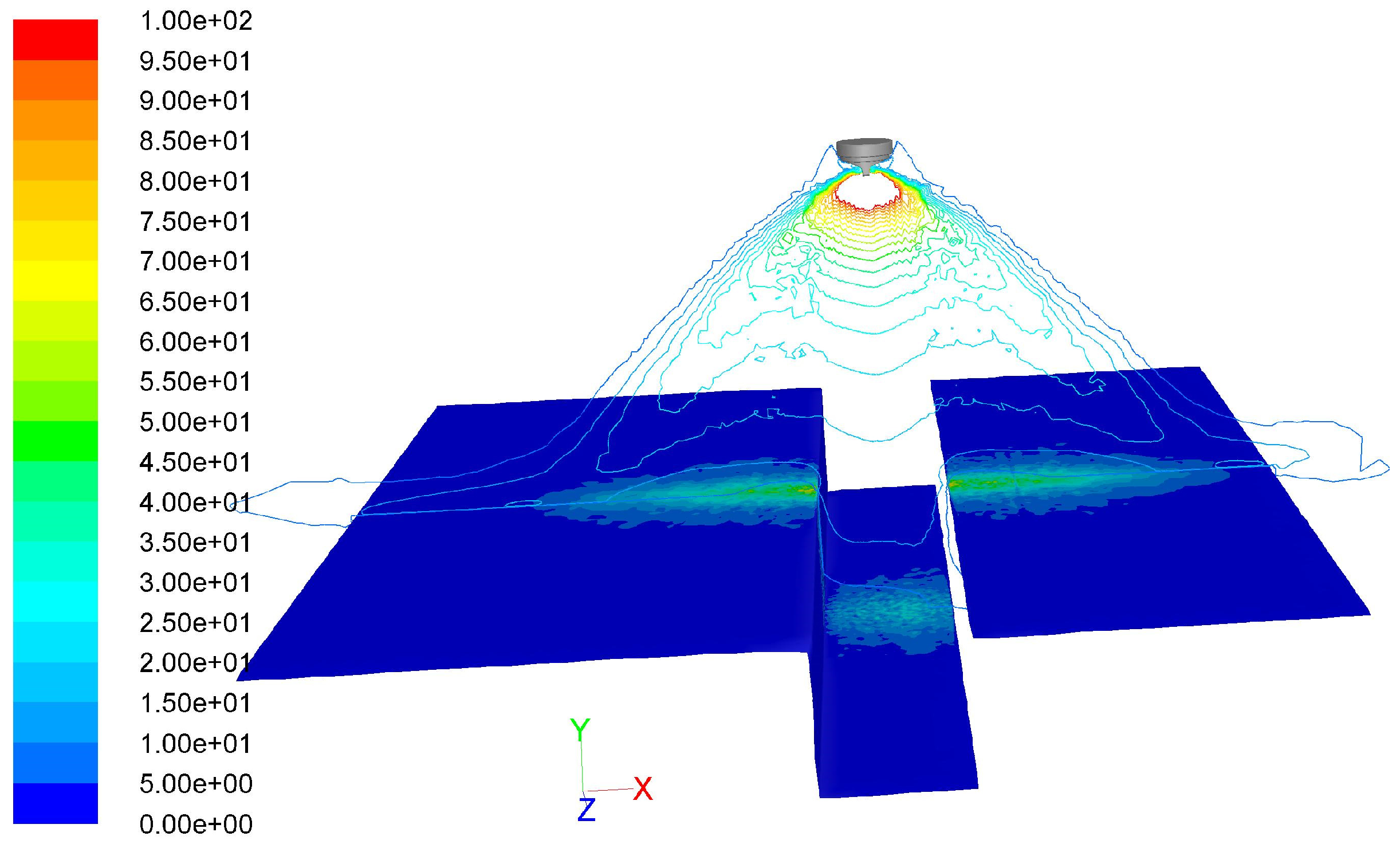
In order to verify the applicability of the numerical approach (especially the method for creating initial droplet conditions), additional tests were performed by purposefully increasing the complexity of the target geometry and the alignment of the atomizer. The target geometry considered herein is shown in
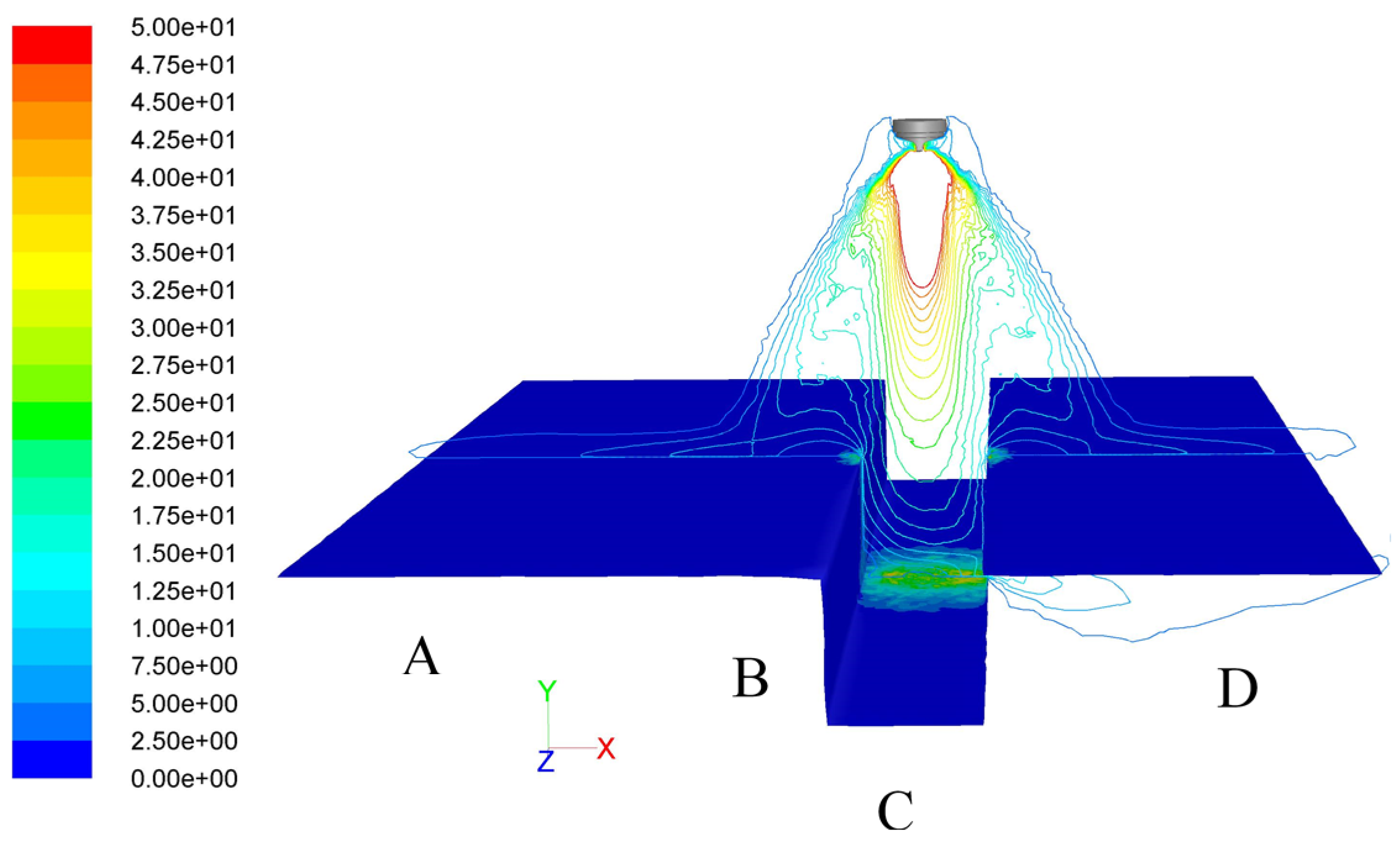
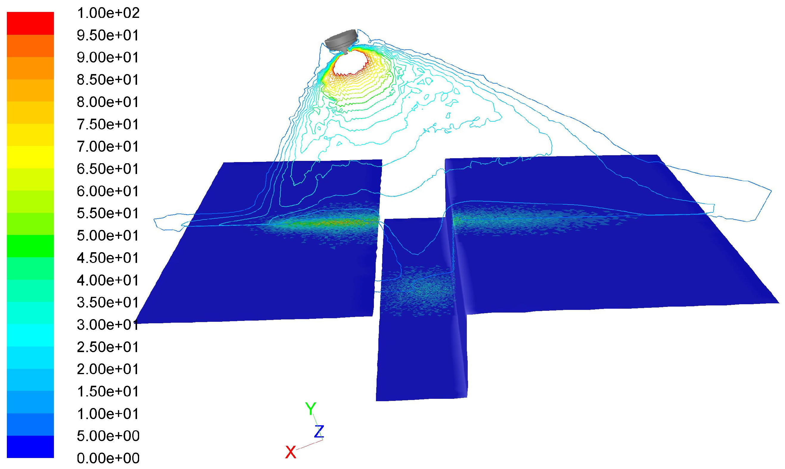
Figure 9. Essentially, it is a stylized rear part of a car body with a water groove. The 3D target consists of four panels. The atomizer is located at the center directly above and (initially) perpendicular to panel C. The same droplet injection data that were used for the simulations with the flat plate were used here. As an example, velocity contours in a cross section through the center of the atomizer for two shaping air flow rates are shown in
Figure 9 and
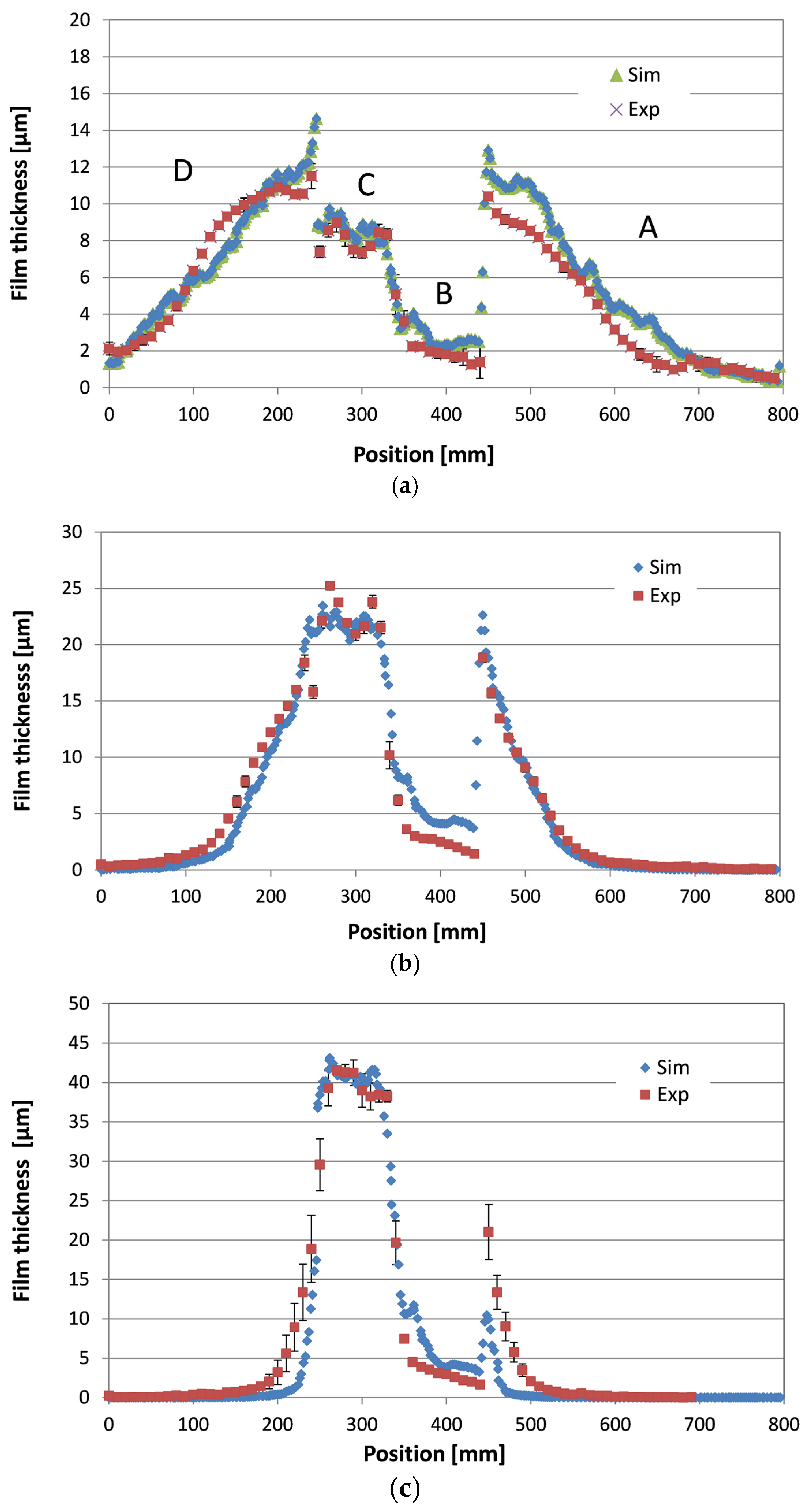
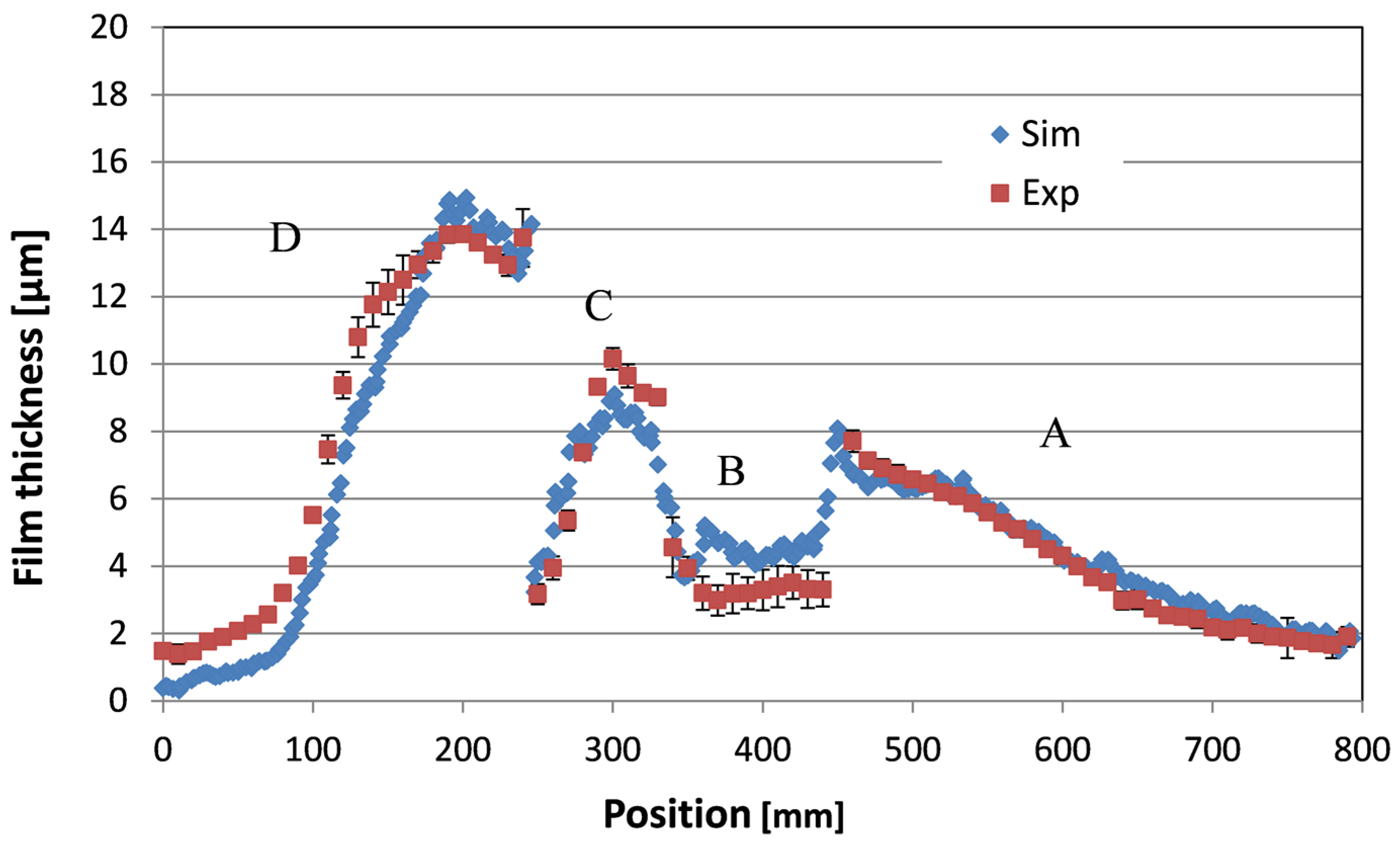
Figure 10, respectively. The liquid paint is distributed mainly on panels A, C, and D for the flat spray with the shaping air flow rate of 360 L/min. For the quasi round spray, almost all of the liquid paint is deposited on panel C. Detailed comparisons of the measured and the simulated film thickness distributions are depicted in
Figure 11. Error bars in the measured film thickness distributions were derived based on a few film thickness profiles in the center region on the 3D-target. Higher standard deviations of the measured film thickness were observed at the panel edges or corners, especially for the round spray.
Finally, the spray painting simulation with an inclination angle of 20° between atomizer axis and panel C was carried out. The velocity contours overlaid with the static film thickness distribution on the work piece and the comparison between simulation and experiment are shown in
Figure 12 and
Figure 13. Clearly, a reasonably good agreement between the measurements and the simulations has been obtained both without inclined atomizer (
Figure 11) and with inclined atomizer (
Figure 13), except at positions very close to the edge. Based on the numerical simulation results, the numerical approaches used in this study can be put into use for industrial computations of spray painting using a pneumatic atomizer with complicated substrate geometries and arbitrary atomizer alignments.
5. Conclusions
In this paper, a numerical simulation of the spray coating process using a pneumatic atomizer has been presented. The compressible airflow was directly calculated from the nozzles.
Droplet size distributions were measured by applying a Spraytec Fraunhofer-type particle sizer. It was found that for a given paint material, the atomization process—and in particular, the droplet size distribution—depends not only on the atomizing air flow rate, but also on the shaping air flow rate. Based on the experimental results of film thickness distributions on a flat plate and air flow field around the atomizer nozzles, the injection model for calculating initial conditions for the droplet trajectory calculation was created, which takes into account the influence of the operating conditions on the droplet size distribution. The droplet phase calculations were then carried out by using the obtained injection data that were set very close to the nozzle. In this way, the spray painting simulation can be used for complex geometries of work pieces and arbitrary alignments of the atomizer, which is meaningful for practical applications.
Special attention was also paid to the verification of the current numerical approach by using a complex work piece geometry and an inclined atomizer alignment. The calculated dynamic film thickness distributions on the work piece were compared with measurements. A quite good agreement between the simulation and the experiment was obtained.
Acknowledgments
This study was partly funded by the BMW in Germany. We would like to thank our colleague Paustian for his assistance in the experiments.
Author Contributions
Qiaoyan Ye wrote the paper. Qiaoyan Ye and Karlheinz Pulli carried out the numerical simulations.
Conflicts of Interest
The authors declare no conflict of interest.
References
- Ye, Q.; Domnick, J.; Khalifa, E. Effect of Inlet and Boundary Conditions on the Numerical Modelling of the Spray Coating Process Using a Pneumatic Atomizer. In Proceedings of the 10th Workshop on Two-Phase Flow Predictions, Merseburg, Germany, 9–12 April 2002.
- Domnick, J.; Lindenthal, A.; Rüger, M.; Sommerfeld, M.; Svejda, P. Zwischenbericht I zum AiF-Forschungsvorhaben 9076: Entwicklung und Anwendung der PDA-Messtechnik für die Bestimmung des Oversprays in der Lackiertechnik, Bericht des Lehrstuhls für Strömungsmechanik 393/I/93; Universität Erlangen-Nürnberg: Erlangen, Germany, 1993. (In German) [Google Scholar]
- Domnick, J.; Lindenthal, A.; Tropea, C.; Xu, T.-H. Application of Phase-Doppler anemometry in paint sprays. At. Sprays 1994, 4, 437–450. [Google Scholar]
- Lindenthal, A. Verbesserung der Effizienz der pneumatischen Lackapplikation mit Hilfe von Phasen-Doppler-Anemometrie-Untersuchungen. Ph.D. Thesis, Universität Erlangen-Nürnberg, Erlangen, Germany, 1997. [Google Scholar]
- Diwakar, R.; Fansler, T.D.; French, D.T.; Ghandi, J.B.; Dasch, C.J.; Heffelfinger, D.M. Liquid and vapor fuel distributions from an air-assist injector-an experimental and computational study. SAE Int. 1992. [Google Scholar] [CrossRef]
- Cheng, D.L.; Lee, C.F. Numerical studies of air-assisted sprays. At. Sprays 2002, 12, 463–500. [Google Scholar] [CrossRef]
- Guézennec, N.; Poinsot, T. Large eddy simulation and experimental study of a controlled coaxial liquid-air jet. AIAA J. 2010, 48, 2596–2610. [Google Scholar] [CrossRef]
- Fogliati, M.; Fontana, D.; Garbero, M.; Vanni, M.; Baldi, G. CFD simulation of paint deposition in an air spray process. JCT Res. 2006, 3, 117–125. [Google Scholar] [CrossRef]
- Desjardins, O.; McCaslin, J.O.; Owkes, M.; Brady, P. Direct numerical and Large-Eddy simulation of primary atomization in complex geometries. At. Sprays 2013, 23, 1001–1048. [Google Scholar] [CrossRef]
- Lebas, R.; Menard, T.; Beau, P.A.; Berlemont, A.; Demoulin, F.X. Numerical simulation of primary break-up and atomization: DNS and modelling study. Int. J. Multiph. Flow 2009, 35, 247–260. [Google Scholar] [CrossRef]
- Hirt, C.W.; Nichols, B.D. Volume of fluid (VOF) Method for the dynamics of free boundaries. J. Comput. Phys. 1981, 39, 201–225. [Google Scholar] [CrossRef]
- Shen, B.; Ye, Q.; Tiedje, O.; Westkämper, W. Primary Breakup of a Paint Liquid by a Coaxial High-Speed Gas Jet Used in Spray Painting Processes. In Proceedings of the 13th Triennial International Conference on Liquid Atomization and Spray Systems, Tainan, Taiwan, 23–27 August 2015.
- Ye, Q.; Shen, B.; Tiedje, O.; Domnick, J. Investigations of spray painting processes using an airless spray gun. J. Energy Power Eng. 2013, 7, 74–81. [Google Scholar]
© 2017 by the authors; licensee MDPI, Basel, Switzerland. This article is an open access article distributed under the terms and conditions of the Creative Commons Attribution (CC-BY) license (http://creativecommons.org/licenses/by/4.0/).


