3.1. Characterizing the Coatings
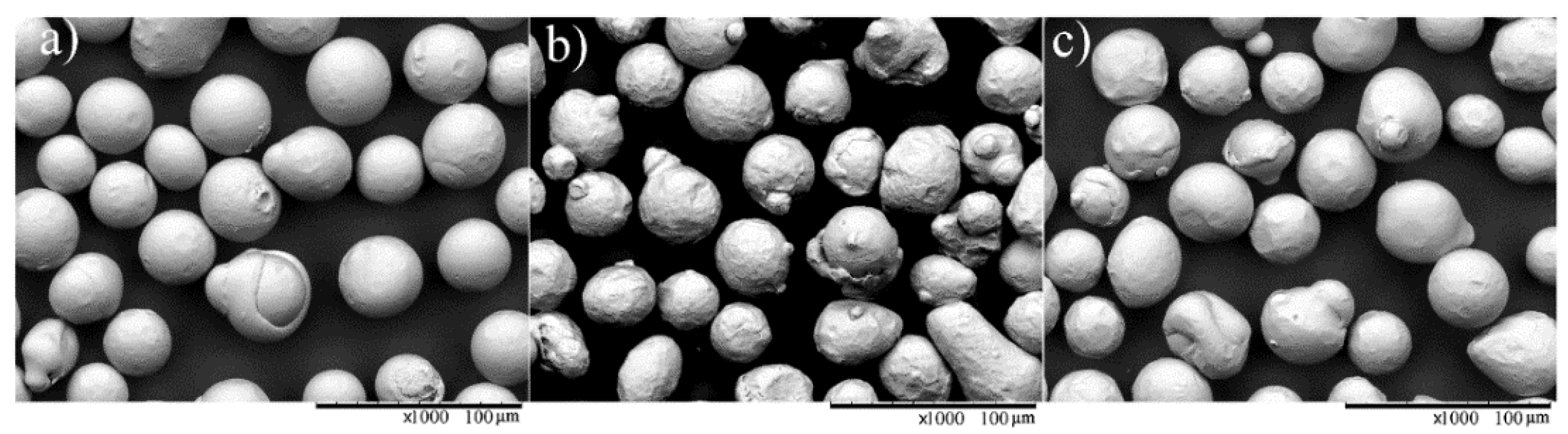
Micrographs of the as-sprayed Fe- and Co-based coatings are shown in
Figure 2a–f. All coatings showed a lamellar structure with elongated impacted splats parallel to the substrate surface. This lamellar structure was most significant in the FeNiCr coating, which implies that the low-alloyed Fe-based powder was better melted during spraying.
Porosity has been shown as an important parameter that can significantly influence the corrosion performance of thermal spray coatings [
8,
19,
40,
41]. The pores permit the electrolyte to penetrate and attack the substrate chemically [
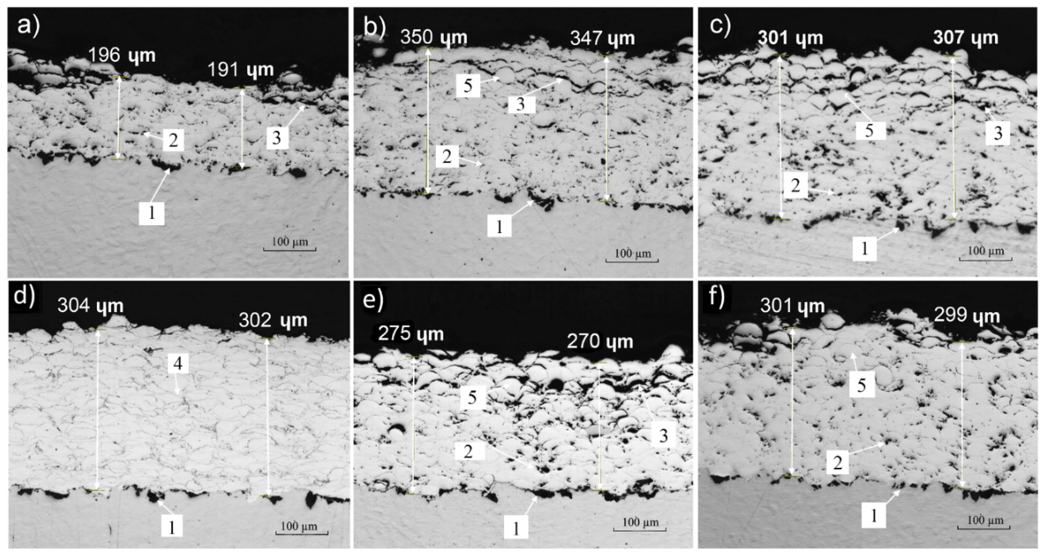
42]. The porosity level was low for the FeCrNi, reaching a maximum of 0.1%, while the values were measured at 2.6%, 2.2%, and 4.7% for the FeCrNiC coatings 1, 2, and 3 respectively. The porosity content in the CoCrC1 and the CoCrC2 coatings were measured at 2.9% and 2.2% respectively. Increasing the in-flight particle temperature from 1400 °C in FeCrNiC3 (
Figure 2c) to 1515 °C in FeCrNiC2 resulted in a denser microstructure, as in
Figure 2a,b.
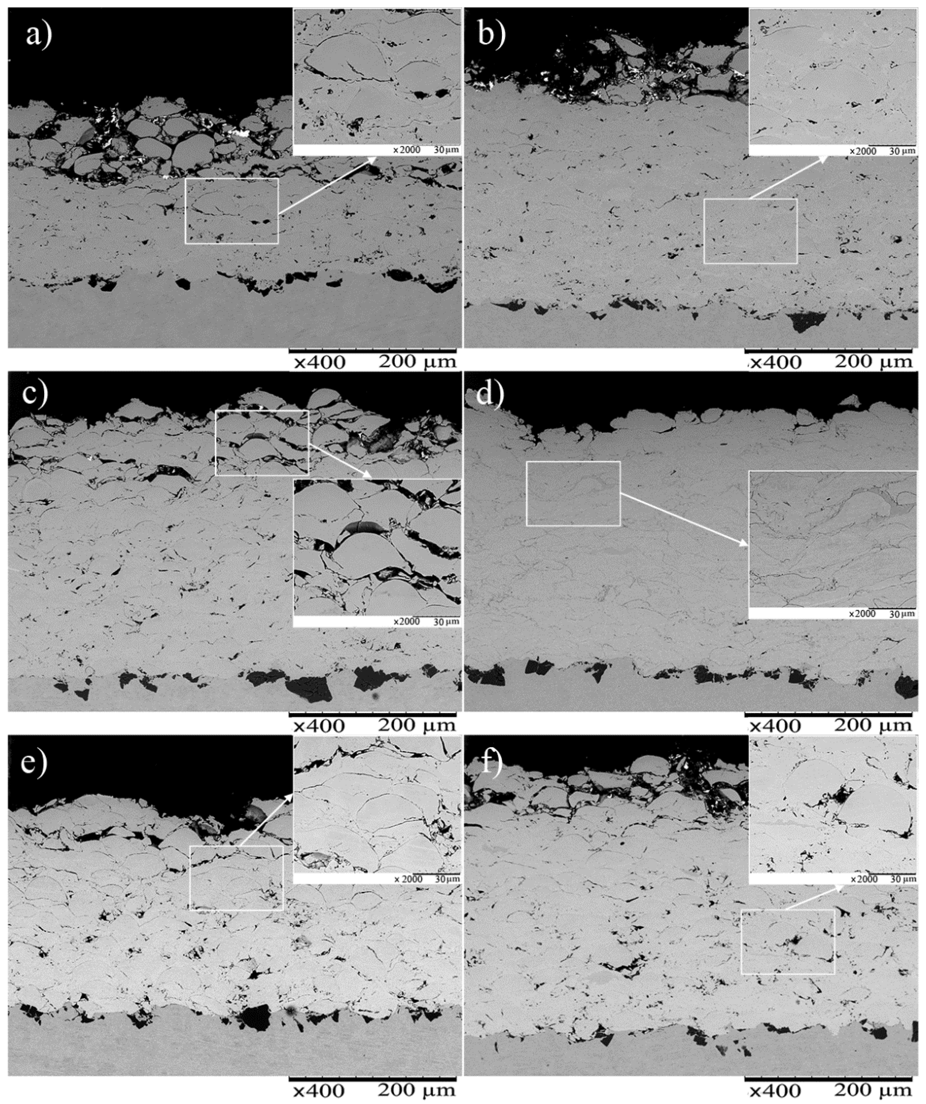
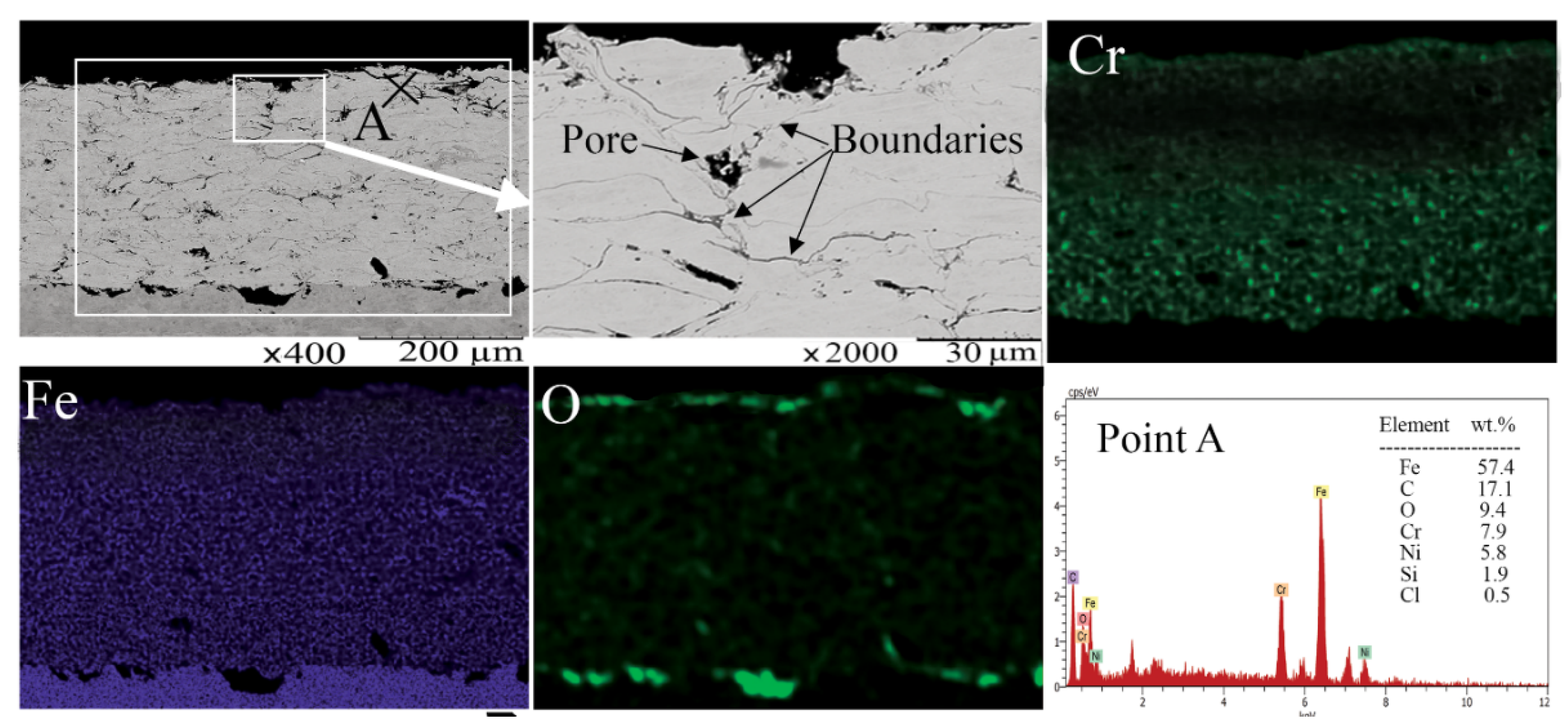
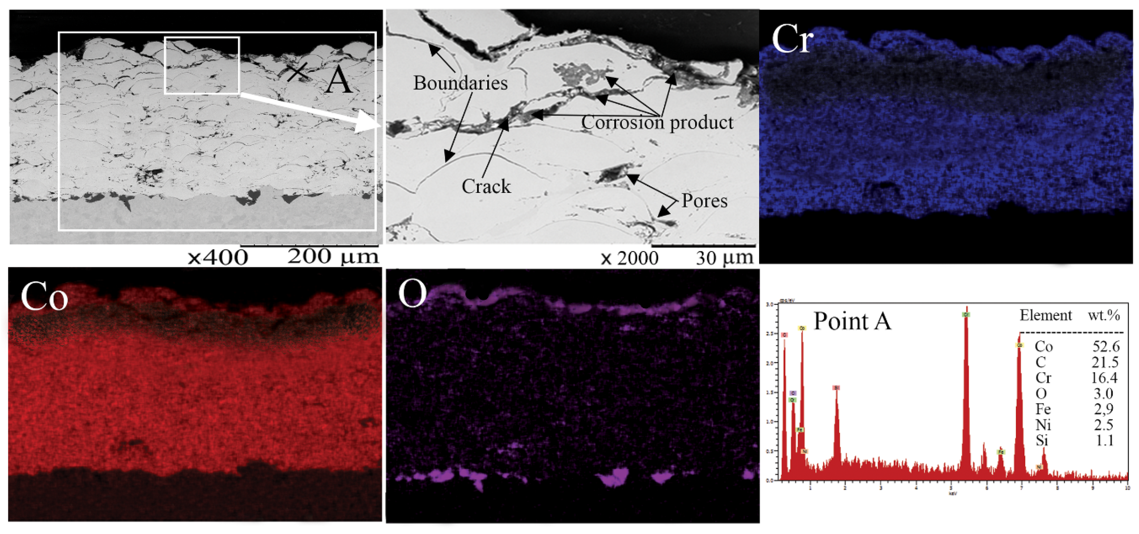
SEM cross-sectional images of the coatings are shown in
Figure 3. All coatings had a fairly porous structure in the near-surface region, however this porosity was expected not to be critical for corrosion resistance, as the pores were shallow and disconnected. The pores were specifically shown to be disconnected in the bottom region of the coating, where the coatings were shown to be well-attached to the substrate. This implied that the corrosive ions would not penetrate deep enough to reach the substrate/coating interface [
7]. Furthermore, there could be a trade-off among coating microstructure, feedstock characteristics, and coating properties. The defects e.g., porosity, or oxide might be compensated by the chemical composition of the coating in terms of coating properties (particularly corrosion) by adding some effective elements, e.g., Cr, Mo or Ni.
The measured thickness, surface roughness, and microhardness of the coatings are given in
Table 4. The respective value is an average of thirty measurements done on three different samples of each coating.
The surface roughness is important in terms of corrosion protection, as a lower surface roughness leads to a lower surface area exposed to the corrosive environment, which can result in less susceptibility to both general and localized corrosion [
43]. The FeCrNiC coating had the highest roughness 3 (8.9 µm) which should be compared to the FeCrNi coating (5.3 µm), which had the smoothest surface. It should be noted that the coating roughness can be decreased in the HVAF by increasing both particle velocity and flame temperature but no such optimization was performed [
24].
For the maximum protection of the substrate, thermal spray coatings have to be dense and defect-free in order to prevent the corrosive ions penetrating through defects (connected pores and cracks) and reach the substrate [
44]. In this case, localized corrosion such as pitting and crevice may occur autocatalytically [
45]. Fe-based coatings free of defects could not be achieved probably because of the inherent characteristics of the thermal spraying process as it is shown in
Figure 3. For instance, the Cr content of the alloy might rapidly oxidize during spraying (due to a great susceptibility of Cr to oxidation). Formation of chromium oxides within the spraying consumes Cr which could be used later in corrosion prevention by formation of the surface passive layer. Therefore, Cr-depletion zones are formed due to the lack of sufficient available Cr which finally leads the coating to be corroded [
46]. Thus, increasing the level of accessible Cr in the coating could improve the corrosion behavior. Altering the thickness of the coating is also reported as a way that can reduce the rate of corrosive ion penetration through defects [
24]. Thinner coating permits the electrolyte to meet the substrate through the coating defect, as it is not sufficiently thick to protect the substrate, unless the chemical composition of the coating (presence of alloying elements such as Cr) compromises the detrimental effect of the defects.
The presence of carbon in the coatings that contains Cr is probably one reason for the higher hardness values in Co-based coatings due to the formation of carbides, particularly Cr
2C
3. Another reason for the higher hardness values of these two coatings could be attributed to cobalt itself, since Co is inherently harder than Fe, and due to inclusions of cobalt oxides, a finer lamellar microstructure, and the presence of carbides, mainly Cr
2C
3, because of the presence of C and Cr in the feedstock Co-based powder. It is well understood that an increase in the level of coating porosity decreases the coating hardness [
47]. However, the CoCrC1 coating shows a higher hardness value than the CoCrC
2 coating, while the former presents a higher pore content than the latter. As the hardness measurement was performed in the area where the coatings showed dense and compact microstructures, the hardness values represent the hardness of the particles impacting the substrate, regardless of the level of pores around them.
The fairly high scatter in the microhardness values, might be due to the presence of heterogeneities in the composition of the coatings. This scatter enhances the coating sensitivity to some certain types of corrosion, particularly microgalvanic corrosion.
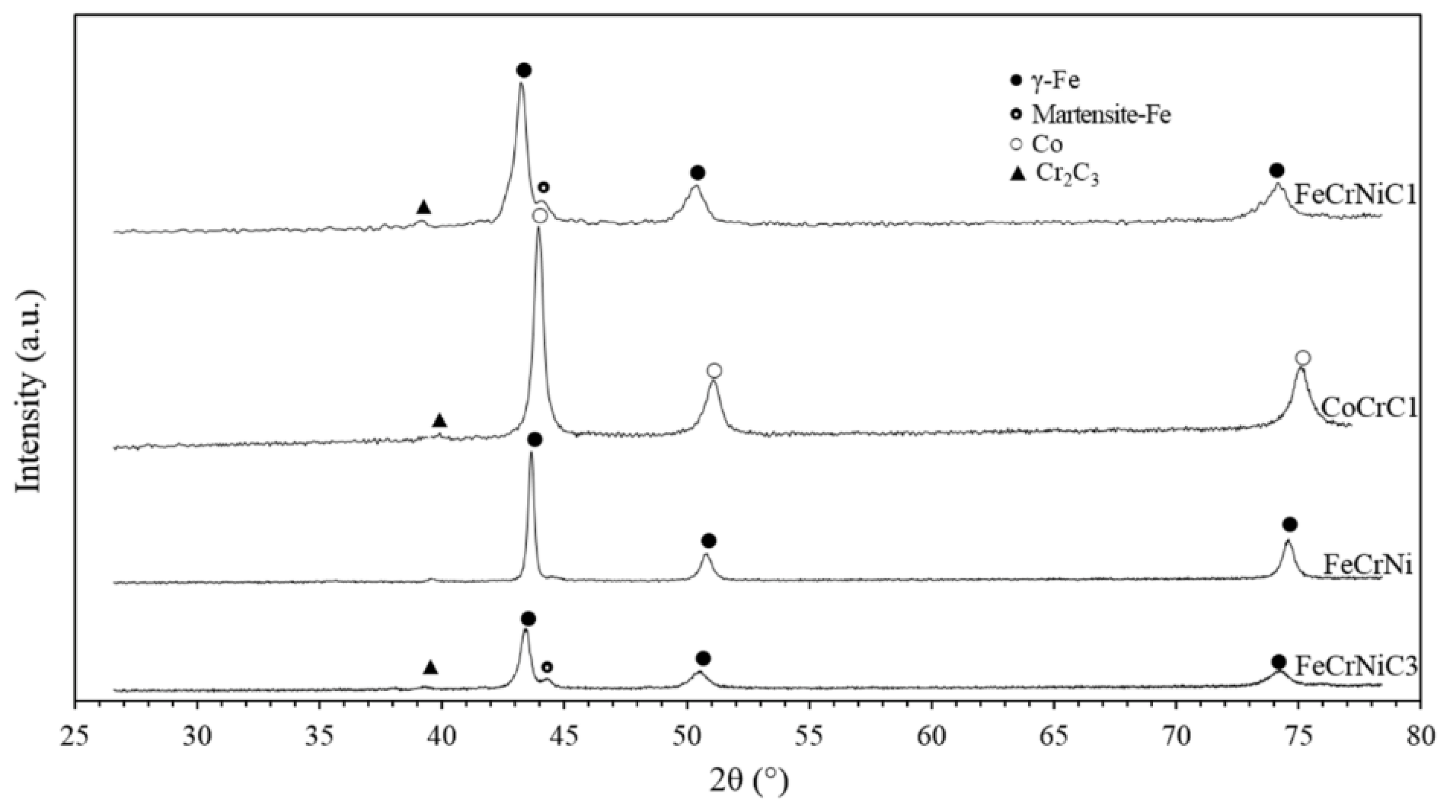
The phase identification of XRD patterns (
Figure 4) showed the presence of an austenitic (γ) matrix in the Fe-based coating, Co phase in Co-based coatings. A slight martensitic phase was also detectable which might be due to the high cooling rate during particle solidification. No σ-FeCr phase was observed which is susceptible to be formed at low particle cooling rate. A minor presence of Cr
2O
3 is indicated due to the increase of the low intensity peak at 38°. The XRD analysis was unable to identify any other presence of oxides, which might be due to the overall high roughness of the coatings [
4].
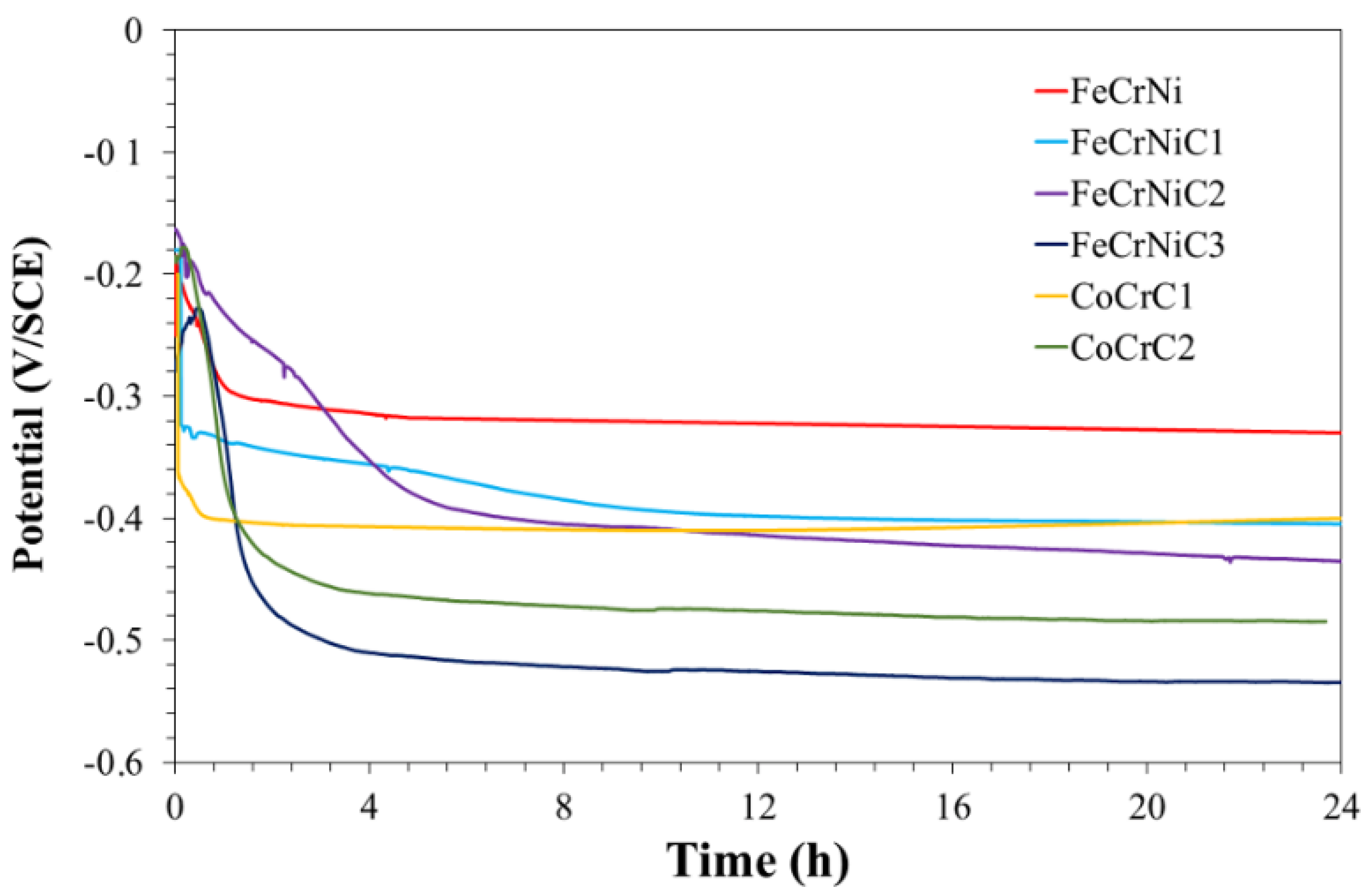
3.2. OCP
The penetration of the corrosive species of the electrolyte along the coating thickness towards the substrate was evaluated by OCP measurements at up to 24 h of immersion (
Figure 5). Higher potential values were measured for the Fe-based coatings (FeCrNi and FeCrNiC1) than both Co-based coatings. This implies that the Fe-based coatings have a better barrier effect compared to both Co-based coatings. The reason for this difference is probably attributed to the lack of interconnected porosity in the Fe-based coatings.
At the very early stage of the test, both Co-based coatings showed an initial low potential, which slowly increased and was later followed by a decrease over time. A potential drop at the beginning of the test was also detected for most of the coatings. The initial potential decrease can be due to; (1) the variation in the surface activity primarily due to the electrolyte penetration along the coating; and (2) the dissolution of the initial oxide layer, which was naturally formed, after immersion into the electrolyte. The decrease of potential after the first hours, confirmed the penetration of the corrosive ions through open porosity or localized defects. However, after such a drop, the potential became steady probably due to clogging of open-pores rather than the passivation of the coating. The frequent potential oscillations imply a susceptibility of the coatings to a localized corrosion such as pitting.
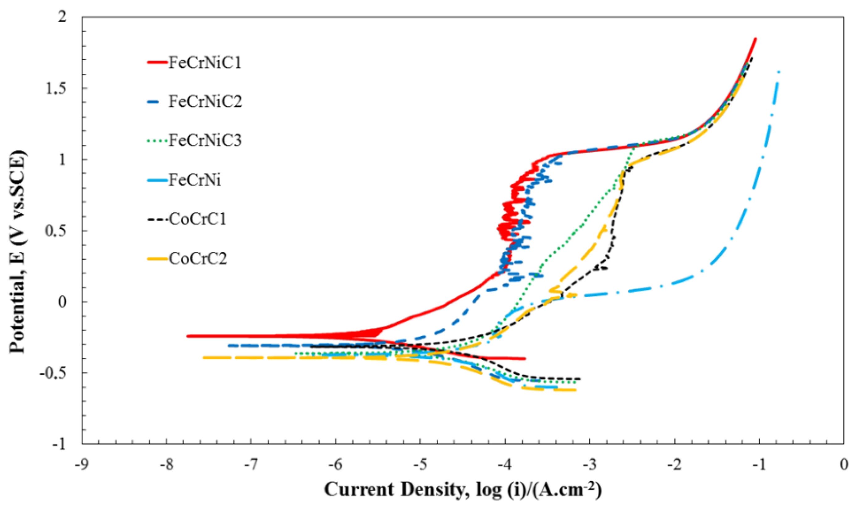
3.3. Potentiodynamic Measurements
Potentiodynamic polarization plots of various coatings immersed in 3.5 wt % NaCl at 25 °C are presented in
Figure 6 to illustrate the overall kinetics of the corrosion process. Electrochemical parameters including the corrosion potential (
Ecorr), corrosion current density (
icorr), anodic (β
a) and cathodic (β
c) Tafel slopes, and polarization resistance (
Rp), derived from the potentiodynamic polarization plots in
Figure 6, are given in
Table 5.
Apart from the FeCrNiC1 coating which had a potential of −0.25 V, the Ecorr of the other coatings varied from −0.31 to −0.38 V, thus showing negligible differences between those samples thermodynamically. The icorr varied from 0.9 to 9.4 μAcm−2. The FeCrNi coating had a high passive current density (ipass) combined with a narrow passive region and it even underwent active dissolution at the low potential without any visible passivation.
The lowest corrosion current density was observed for the FeCrNiC1 coating (0.9 μAcm−2), which is due to the formation of a stable and protective superficial layer. It was not possible to find a direct correlation between coating defects and icorr. The reason is probably the elemental composition in addition to that of the defects which can play a significant role in the corrosion process.
The FeCrNiC3 and CoCrC1 coatings showed a passivation stage at a relatively high
ipass. The reason for this behavior might be the structural defects in these coatings including pores and microcracks,
Figure 6. The FeCrNi coating showed a similar behavior which might be due in this case to the lamellar structure of this coating. The presence of the lamella boundaries hinders the outward migration of Cr to reach the top surface of the coating which eventually leads to weak passivation. The FeCrNiC1 and FeCrNiC2 coatings showed an exhibited passivation stage at low
icorr with some tiny fluctuations. The fluctuations imply a continuous process of active solution and passivation. The transpassive potential (
Etrans) of these coatings was about 1.0 V combined with a broad passive region, which confirmed that these coatings had an ability to prevent localized corrosion. Contrarily, the very limited passive region of the FeCrNi coating illustrated a low ability to hinder localized corrosion. The
Ecorr value was lower in the Co-based coatings compared to the FeCrNiC coatings, which confirms that these coatings were more active as galvanic couples. The passivation stage of the Co-based coatings occurred at higher
icorr compared to the FeCrNiC coatings, implying a poor ability for the surface passive films to be stable. However, broad passive regions were identified by similarly high
Etrans, 1.0 V, as observed in the FeCrNiC coatings. Thus, the Fe-based coatings, especially FeCrNiC1, seem efficient as a protective barrier with excellent corrosion properties and ability to prevent localized corrosion in aggressive environments.
The high resistance to localized corrosion such as pitting of the high-alloyed Fe-based coatings was considered to be determined by the presence of Cr-rich passive surface films formed on the Fe-based coatings, which prevented further attack by the corrosive solution. Moreover, Mo content of the coating could also reduce the possibility of pitting, improving the corrosion resistance and passivating ability. It is well understood that Mo could control the dissolution of Cr during passivation [
40]. FeCrNiC1 and FeCrNiC2 coatings which contained high amounts of Cr, Mo, and Ni were observed to have very low
icorr and, thereby, high resistance to corrosion. This indicates that the corrosion resistance of the Fe-based coatings is sensitive to the microstructure characteristics which were shown to be dependent on the spraying parameters.
It can be hypothesized that “passive-like” stages were produced due to the formation of a thin passive oxide film. However, defects such as pores, oxide inclusions, and interlamellar boundaries led to an interruption in perfect passivity, as these defects act as barriers for diffusion of beneficial elements (such as Cr) for passivation [
4,
8,
24,
48,
49]. The initial breakaway of a “passive-like” stage might be connected to the galvanic microcells or selective corrosion along lamellae boundaries, based on a mechanism identical to pitting. The former produces quite low damage; therefore, it can be attributed to lower anodic
icorr; instead, the latter inflicts more damage, resulting in higher anodic
icorr.
The largest polarization resistance
Rp was consistently reported for the FeCrNiC1 coating (43.9 kΩcm
2) due to the coatings low
icorr and quite high β
a and β
c.
Table 5, High β
a and β
c lead to lower anodic and cathodic current at the same overpotential during the polarization measurements which consequently results in higher
Rp.
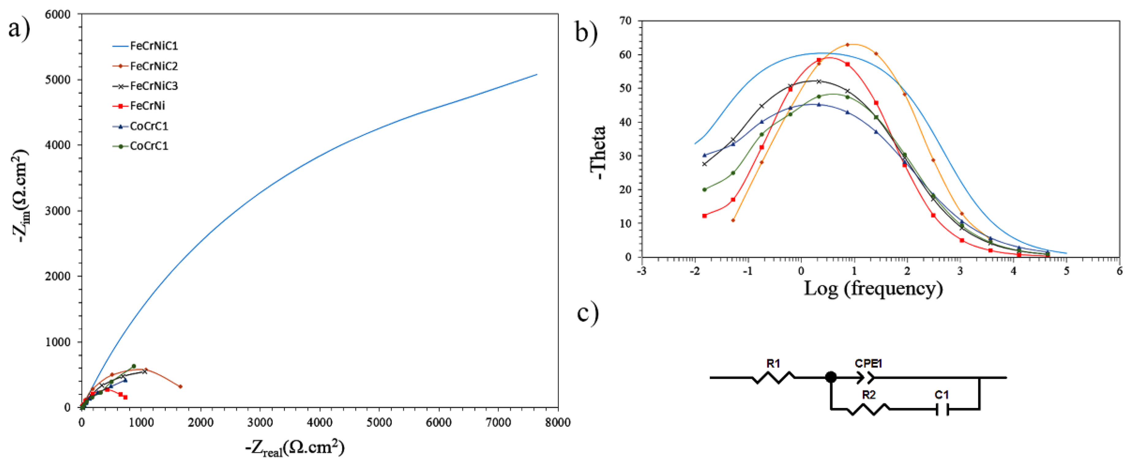
3.4. EIS (Electrochemical Impedance Spectroscopy)
EIS is a non-destructive method that relies on a small AC-voltage signal (20 mV), which is applicable for resistance and capacitance studies of the coatings through a fit of the data to a proper circuit model. Nyquist and Bode diagrams of coatings in 3.5 wt % NaCl solution is shown in
Figure 7a,b. During the exposure, corrosive ions penetrated the defects through the coating before reaching the substrate. Thus, at the beginning of the test, the electrochemical behavior could be associated with the intrinsic properties of the coating.
The EIS results show the presence of one capacitive loop for all coatings. The diameter of this capacitance loop can be linked to the corrosion resistance. The fact that only one single time constant was gained might be less likely due to the short exposure time. The electrolyte failed to penetrate through the whole thickness of the coating and thus reaching the coating/substrate interface. Thus, the electrochemical characteristics derived from the EIS measurements could be attributed to the Faradaic process (as a result of charge transfer across the interface) that comprised the coating reactivity [
50].
The formation of corrosion products showed a pore partial sealing in small pores [
51]. However, these corrosion products had poor adherence, which eventually led the electrolyte to penetrate further through the pores.
Consequently, a simple equivalent circuit to describe the electrochemical behavior of coatings was suggested, as shown in
Figure 7c. The equivalent circuits included the solution resistance (
Rs), charge transfer resistance in the coating/solution interface (
Rct), and coating double-layer capacitance (
Cdl) described by a constant phase element (
CPE).
The corrosion parameters derived from the equivalent electric circuit are given in
Table 6.
Rct describes the ability of the coating to inhibit ion transfer at the solution/coating interface. It can be observed that
Rct decreased with the increase of defects within the coating and most likely due to the dissolution of oxides because of chloride ion adsorption and chloride attack of the passive film. The higher
Rct confirmed the lower exposed coating/electrolyte interface and therefore lower coating open porosity and accordingly less corrosion of the coating. This confirms a better corrosion resistance of the FeCrNiC1 coating compared to both Co-based coatings. The high-alloyed Fe-based coating (FeCrNiC1) showed a better corrosion protection performance compared to the low-alloyed Fe-based (FeCrNi) in the 3.5 wt % NaCl solution.
CPE is generally employed to model the behavior of double layers in real electrochemical processes [
52].
CPE means the double layer capacitance at the solution/coating interface which includes the interfaces between the top surface of the coating and the solution and also the surface of defects with the solution. The measured value of
CPE (
Table 6) suggests that the porosity increased during the immersion, accordingly, due to the penetration of the solution. The “plugging effect” resulting from the accumulation of corrosion products in defects might be a reason for the increase in
CPE [
2,
28].
The time constants
n of all the coatings attributed to the charge transfer reaction were relatively similar, confirming that the same electrochemical mechanism occurred. By definition, the capacitance has a direct relationship to the electrical permittivity of the material and to the total exposed surface area as well as an inverse relationship with the distance between the two conductive plates [
53]. As the electrical permittivity of the 3.5 wt % NaCl solution and the distance (the thickness of the electrical double layer formed on the coating surface) were fixed, a decrease of the double layer capacitance might be associated with a lower electrolyte penetration (
i.e., lower overall area) and thus, lower open porosity [
24].


