1. Introduction
The energy sector is the largest CO
2 emitter globally [
1]. One concept to reduce the CO
2 emissions originating from the use of fossil fuels in power generation is carbon capture and storage (CCS) [
2,
3]. Integrated oxy-combustion is considered as one of the most promising technologies to facilitate CO
2 capture, because it can be built as a retrofit solution for existing boilers [
4]. The oxy-fuel process uses oxygen or oxygen-enriched air to reduce nitrogen in the flue gas and hence increase the CO
2 content to facilitate more efficient capture.
Oxy-fuel combustion can be expected to differ from combustion in air by modified distribution of fireside temperatures, much reduced NO
x emissions, increased levels of fireside CO
2 and H
2O with small amounts of O
2, Ar, N
2, and some impurities like SO
2 and Cl [
5]. Due to recycling of flue gas in oxy-fired combustion compared to air firing, there is an increased risk of corrosive species enrichment in the flue gas environment [
6,
7]. These changes in the combustion gas chemistry will also affect the chemistry and formation of deposits. This may increase corrosion of the boiler components that are in contact with the combustion and flue gas environment [
8,
9,
10]. Coatings are a promising approach to improve corrosion resistance because existing validated structural steels can be used as base material. Coatings can be tailored by composition and structure to give the best surface protection for selected conditions.
Several steels and alloys have been tested in air- and oxy-fuel combustion conditions [
11,
12,
13,
14,
15]. These include low alloy steels (13CrMo44), ferritic steels (T91, T/P92), austenitic steels (1.4910, Super 304H, TP347HFG, 310N, Sanicro 25 and HR3C), and nickel base alloys (IN617 and IN740). Gagliano
et al. [
11] tested several candidate materials both in laboratory and field tests in advanced ultra-supercritical conditions. They discovered that a material’s resistance to coal ash corrosion is primarily dependent on the chromium content. Alloys containing chromium more than 22 wt % generally exhibited satisfactory corrosion resistance in laboratory tests. The field study showed that materials containing roughly 25 wt % chromium exhibited satisfactory resistance, regardless of the fireside corrosion mechanism. Hussain
et al. [
14] exposed nickel-based thermal spray coatings to corrosion testing simulating fireside corrosion in coal and biomass co-combustion at 650 °C. The best performing coating in the study was NiCr coating with 46 wt % of chromium.
In future power plants, oxy-combustion may cause serious corrosion problems to boiler components. Besides testing present available materials, development of new protective materials is essential. Iron-based high chromium content coatings with aluminium addition offer a promising and readily applied solution [
16], but require further development and research. This paper presents the development of a new Fe-based alloy from thermodynamical calculations to laboratory testing under simulating oxy-combustion. The Fe-based alloy was tested as a coating manufactured by high velocity oxy-fuel (HVOF) thermal spray process and in a hot isostatic pressed (HIP) bulk form.
2. Experimental Section
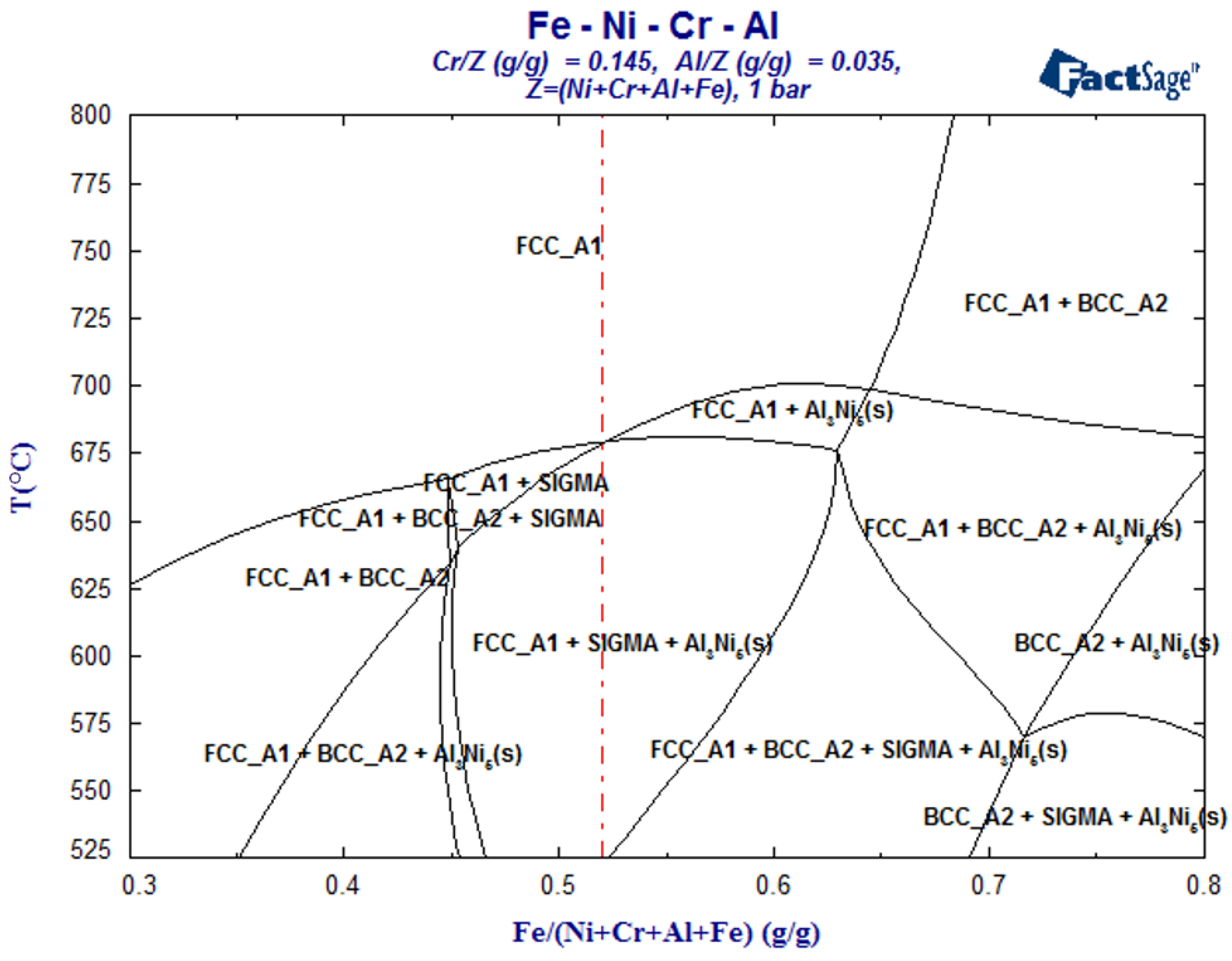
The material tailoring for oxy-combustion conditions began with composition selection by thermodynamic calculation. Iron was chosen as the base material, because it is inexpensive, and cost effective material solutions are valued. The thermodynamic calculations were made with the FactSage 6.3 program using the FSsteel database and a custom-compiled database for the environment and deposit. Based on the calculations (
Figure 1), Fe-30Ni-14.5Cr-3.5Al, the red dotted line in the
Figure 1, was chosen as the material composition. The phase diagram (
Figure 1) shows that at temperatures over 675 °C the structure should be fully austenitic (FCC_A1) with fully soluble alloying elements. The material might have some problems with the formation of a brittle σ-phase under temperature of 675 °C. Additionally Al
3Ni
6 precipitates can form under 675 °C.
Figure 1.
Phase diagram of the designed FeNiCrAl alloy. Selected material composition is marked with a dotted line. FCC_A1 = austenitic and FCC_A2 = ferritic.
Figure 1.
Phase diagram of the designed FeNiCrAl alloy. Selected material composition is marked with a dotted line. FCC_A1 = austenitic and FCC_A2 = ferritic.
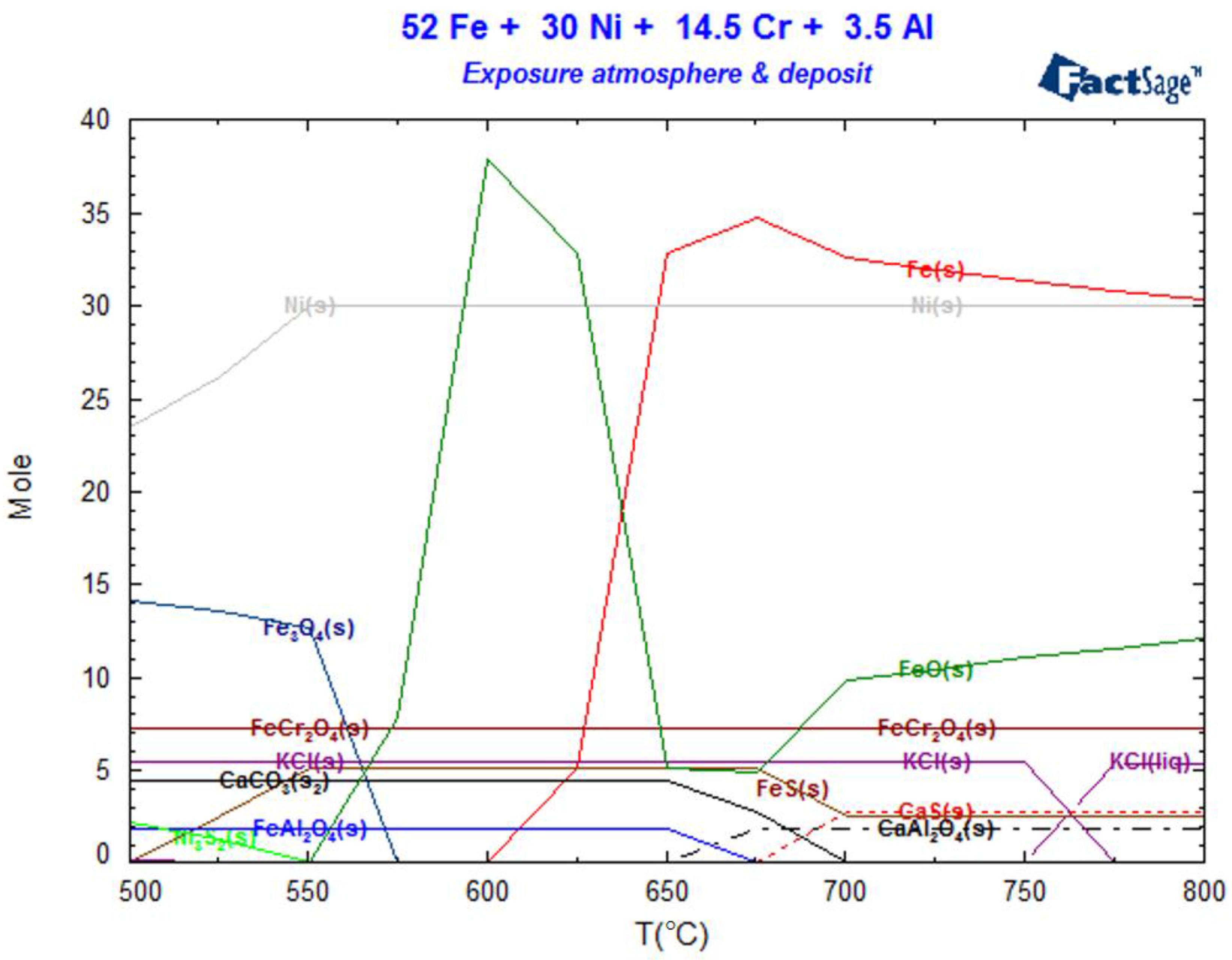
Thermodynamic equilibrium calculations were made with a surplus amount of exposure gases (44% CO
2-30% H
2O-0.6% SO
2-0.2% HCl-N
2) and deposit (CaSO
4-0.55 wt % KCl). The results are shown in
Figure 2, where it can be seen that at 650 °C, the equilibrium favors solid FeCr
2O
4 formation along with smaller amounts of FeO, FeS and FeAl
2O
4 on top of Fe and Ni, which have high stabilities according to the calculation. The salt and gas would react to form solid CaCO
3. Moving to 720 °C solid FeO is increasingly preferred while solid FeS is not. Solid CaAl
2O
4 should be formed instead of FeAl
2O
4 and solid CaS instead of CaCO
3.
Figure 2.
Thermodynamic equilibrium of the selected test material in the test exposure atmosphere, and deposit as a function of temperature.
Figure 2.
Thermodynamic equilibrium of the selected test material in the test exposure atmosphere, and deposit as a function of temperature.
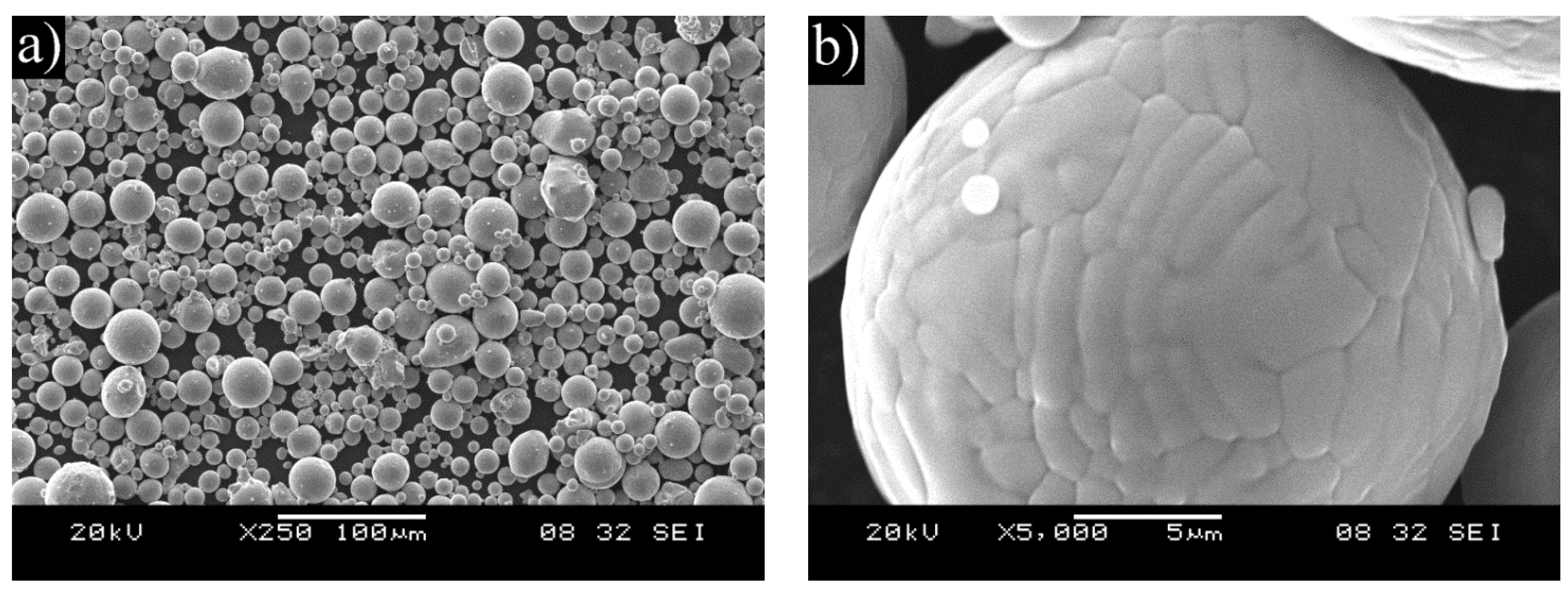
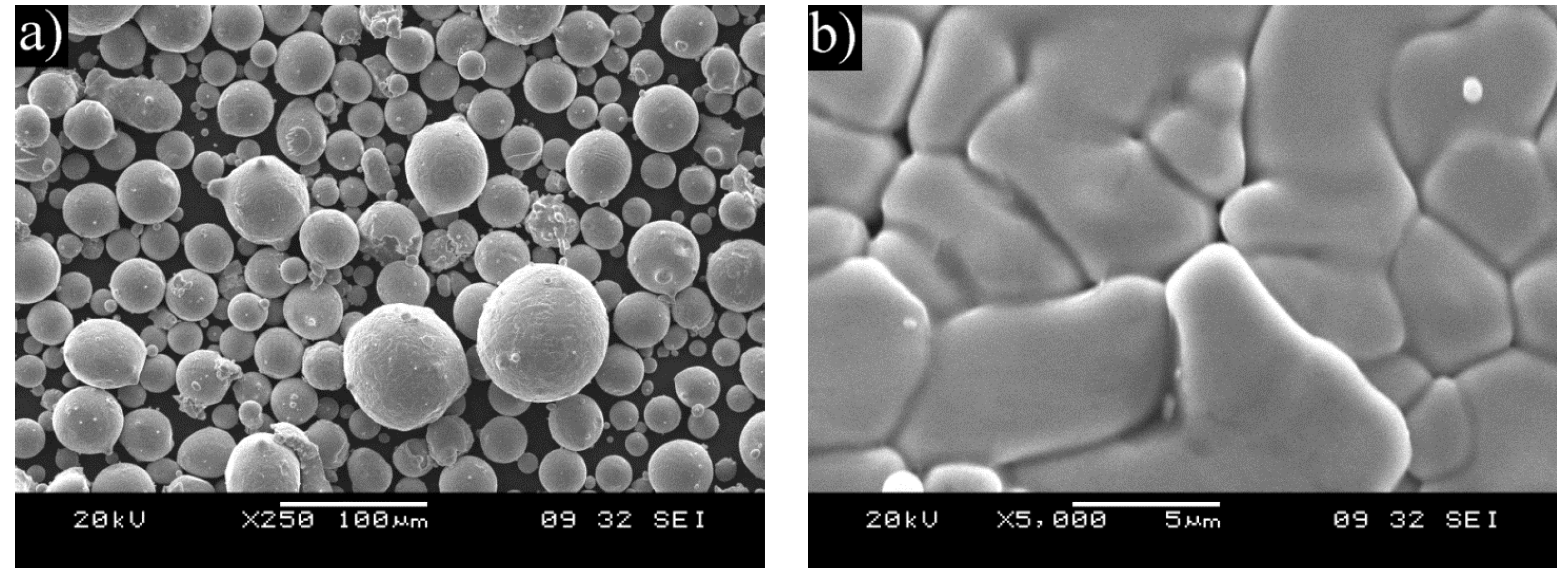
Powder of the selected composition was prepared by a Hermiga 75/5VI high-pressure gas atomizer. The atomizer was a 5 kg batch atomizer with induction melting. Argon was used as atomization gas providing an oxygen level of below 1 ppm. The used atomization gas pressure was 5 MPa and the overpressure in the melt chamber was 0.025 MPa. The melting point of the alloy is around 1450 °C and the melt temperature was 1650 °C. The FeNiCrAl metal alloy was pre-alloyed to ensure homogenous composition. Chamber fraction of the atomized powder was sieved with 45 μm aperture. Undercut was used in thermal spraying and overcut (45–125 μm) in HIP. Cyclone fraction was not used as it was considered too fine.
Thermal spray with an HVOF torch was used for depositing coatings of the manufactured powder on X20CrMoV121 ferritic stainless steel cylinders with prior degreasing and grit blasting. In addition, nitrogen permeability test buttons and plates for cross sectioning were coated. The test buttons for nitrogen permeability are porous discs that allow gas to freely flow though, but dense enough to be coated without issues [
17]. The used torch was DJ Hybrid (Diamond Jet Hybrid) and the -45 μm sieved chamber fraction was used as the powder.
Table 1 presents the used spray parameters.
Table 1.
Coating parameters for HVOF spray of the FeNiCrAl powder.
Table 1.
Coating parameters for HVOF spray of the FeNiCrAl powder.
| Torch | Nozzle | Stand Off | Air | Propane | O2 | N2 | Powder Feed |
|---|
| DJ | 2701 | 230 mm | 400 L/min | 62.4 L/min | 290 L/min | 12.5 L/min | 50 g/min |
Hot isostatic pressing was performed using an Asea Mini Hipper QUINTUS Hot Isostatic Press type QIH-9. The overcut of the chamber fraction of the gas atomized powder was packed in an AISI 316L HIP capsule of Ø27/30 mm × 100 mm using mechanical pressing. The evacuation of the capsule was 24 h at room temperature down to a pressure level of 10−5 mbar. Used HIP parameters were 1150 °C/3 h/1000 bar.
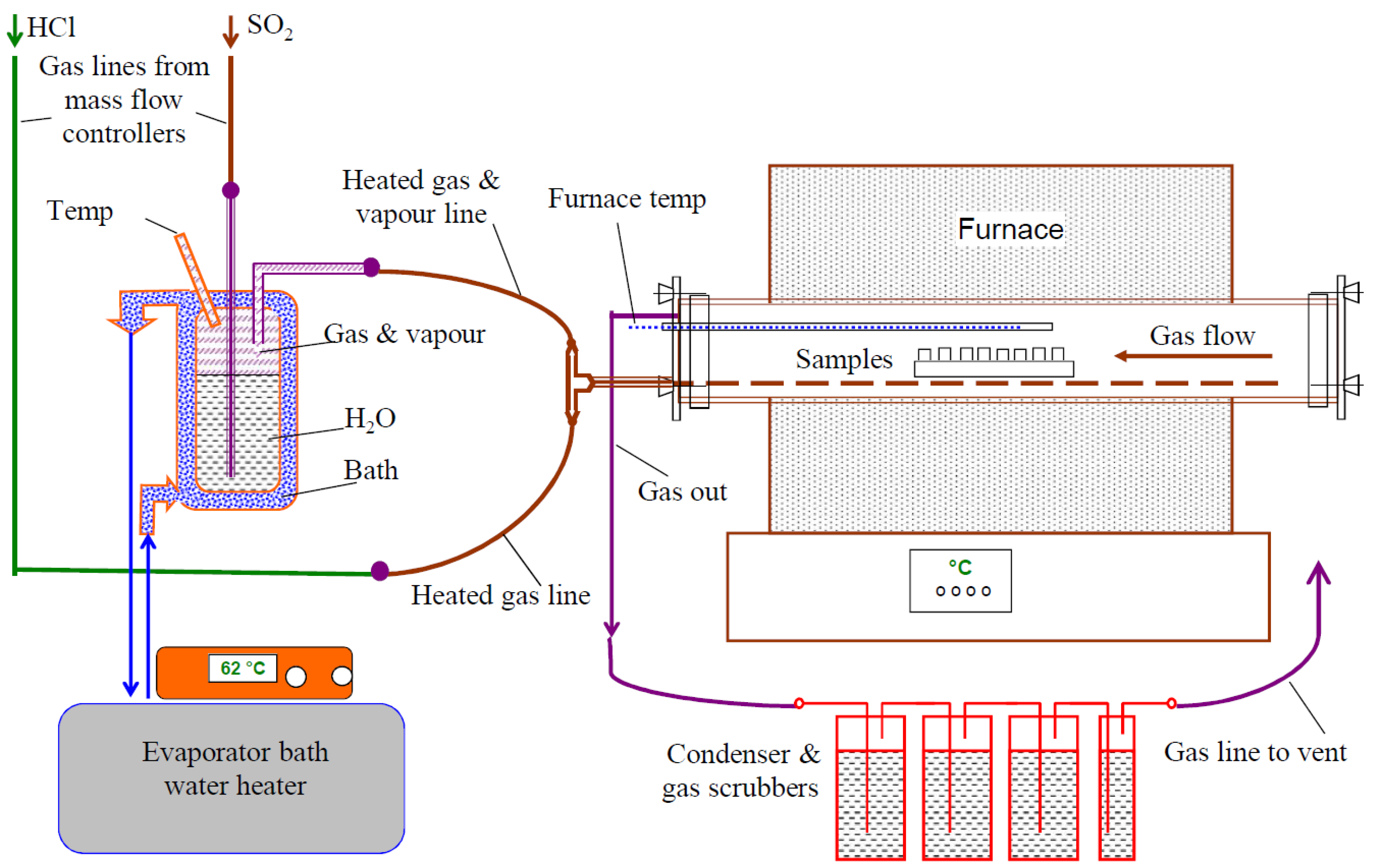
High temperature corrosion testing in oxy-fuel combustion conditions was carried out at VTT in a laboratory scale under isothermal conditions at temperatures of 650 and 720 °C up to 1000 h using a furnace system schematically illustrated in
Figure 3. The furnace consisted of a horizontal ceramic lined reaction tube and mass flow control systems to produce the targeted gas mixtures. The carrier gas mixture was passed through a humidifying unit containing deionized water before the furnace, to add moisture to the gas mixture. For preheating purposes the gas line goes through the length of the furnace tube before releasing the gas mixture at the other end. The used premixed gas composition was 44% CO
2-30% H
2O-0.6% SO
2-0.2% HCl-N
2. During the exposure the specimens were embedded on a CaSO
4-0.55 wt % KCl deposit. Due to space limitations, only one specimen of each type was exposed.
Figure 3.
Schematic figure of the high temperature corrosion test system.
Figure 3.
Schematic figure of the high temperature corrosion test system.
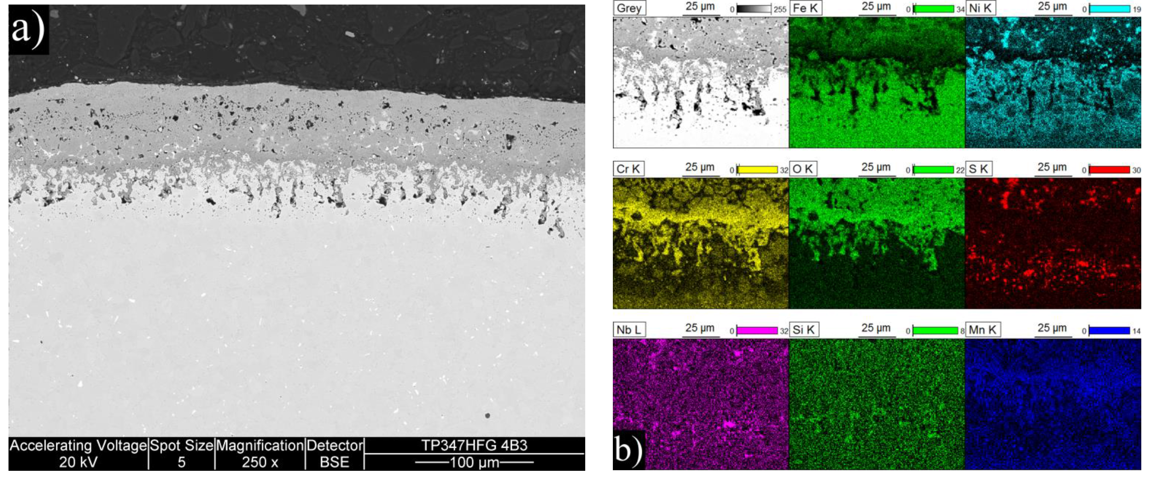
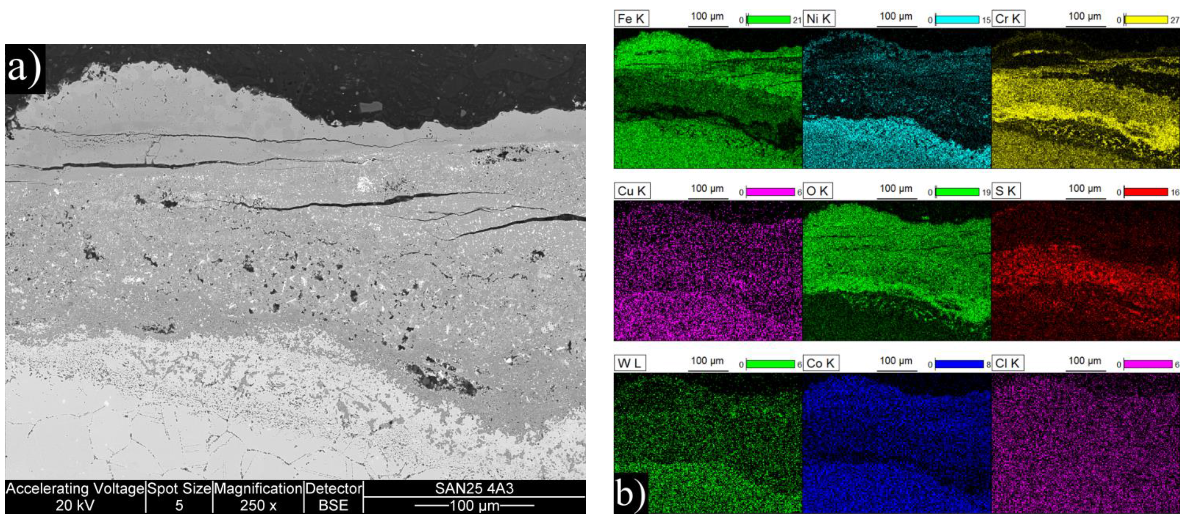
The coated specimen was in the shape of a cylinder with 15 mm diameter and 20 mm length and the surface was left as coated. The HIP’ed specimens were machined from 15 mm diameter bars to a disc shape with 15 mm diameter and 5 mm height and ground to 600 grit surface finish. Sanicro 25 (UNS S31035) and TP347HFG (UNS S34710) specimens with dimensions of 15 mm × 15 mm × 3 mm machined from thick walled tubes were used as reference specimens with the surfaces ground to 600 grit finish.
Table 2 shows the chemical composition of the reference materials.
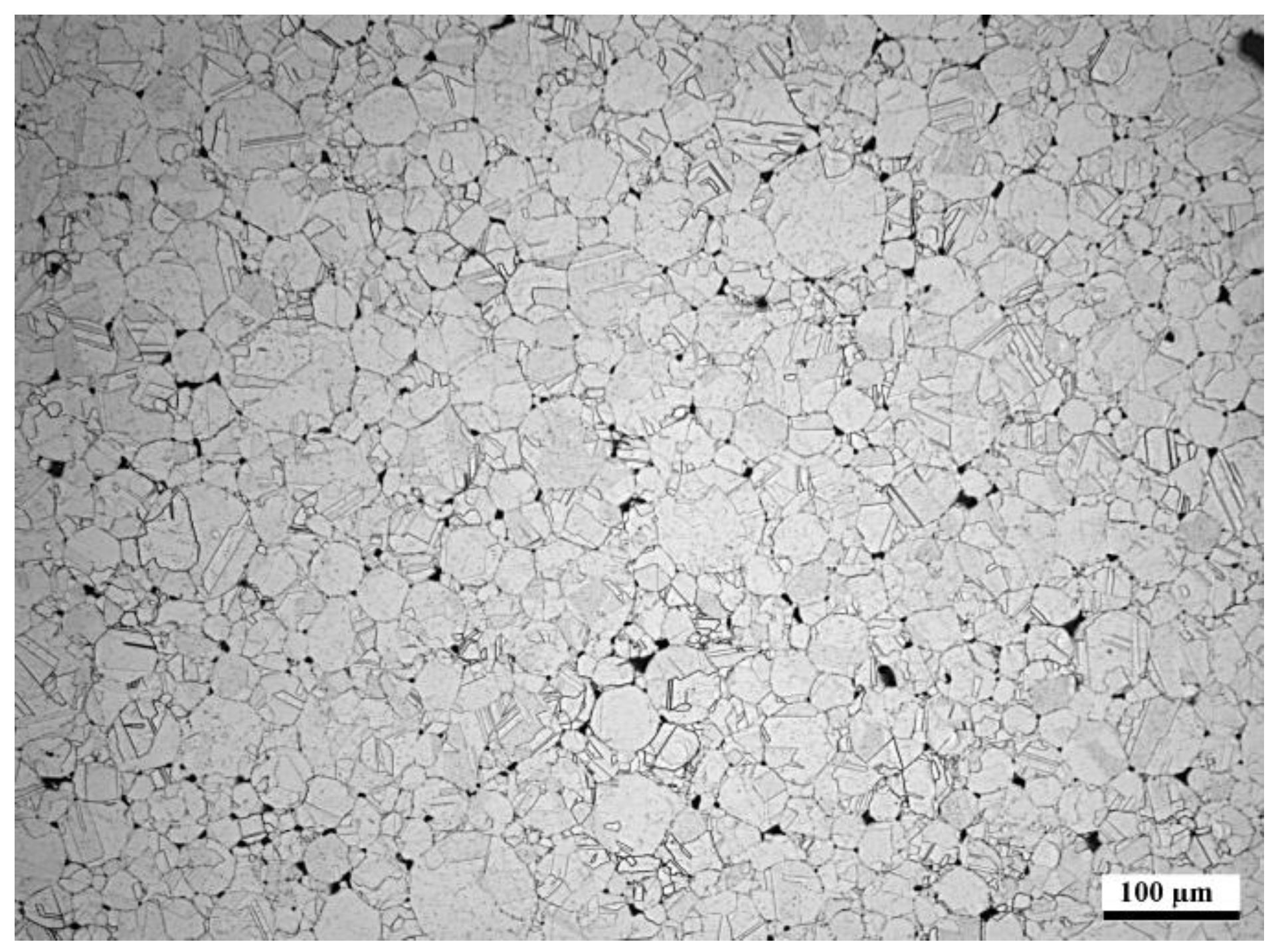
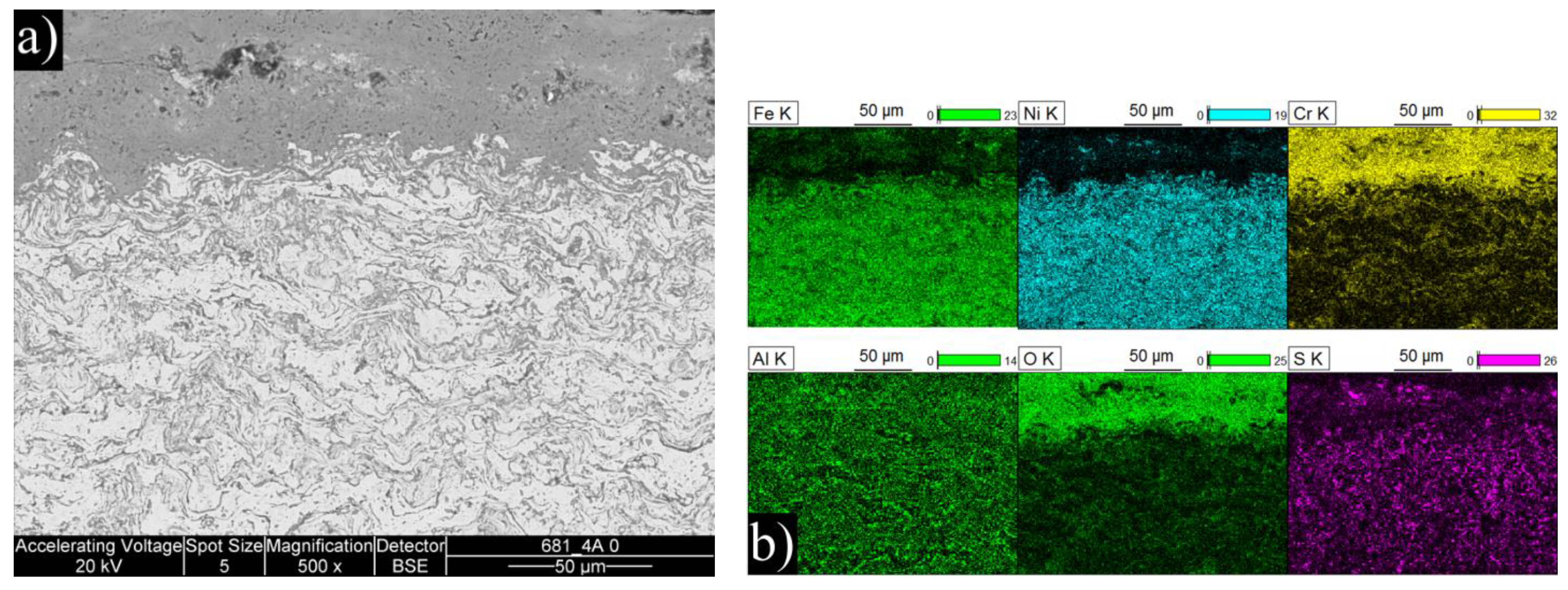
After the exposure in the simulated oxy-fuel combustion, metallographic cross-sections were prepared by cutting the samples, mounting them into resin and grinding and polishing with ethanol. Characterization was performed with an optical microscope and a FEI XL30 ESEM scanning electron microscope (SEM) equipped with a Thermo Fisher Scientific UltraDry energy dispersive X-ray detector (EDX). X-ray Diffraction (XRD) was performed on corrosion products of the coatings after exposure in the highest temperature. The aim of the materials performance assessment was to characterize the morphologies produced during the exposure testing and to determine the extent of metal damage caused to each specimen during the exposure.
Table 2.
Chemical composition of bulk materials Sanicro 25 and TP347HFG by optical emission spectroscopy (OES).
Table 2.
Chemical composition of bulk materials Sanicro 25 and TP347HFG by optical emission spectroscopy (OES).
| Alloy | Cr | Ni | Mo | Nb | Fe | Other |
|---|
| TP347HFG | 18.3 | 11.7 | 0.23 | 0.92 | bal. | 1.64 Mn, 0.33 Cu, 0.4 Si, 0.07 C |
| Sanicro 25 | 22.3 | 24.9 | – | 0.5 | bal. | 3.4 W, 1.5 Co, 2.9 Cu, 0.2 Si, 0.3 Mn, 0.24 N, 0.06C |
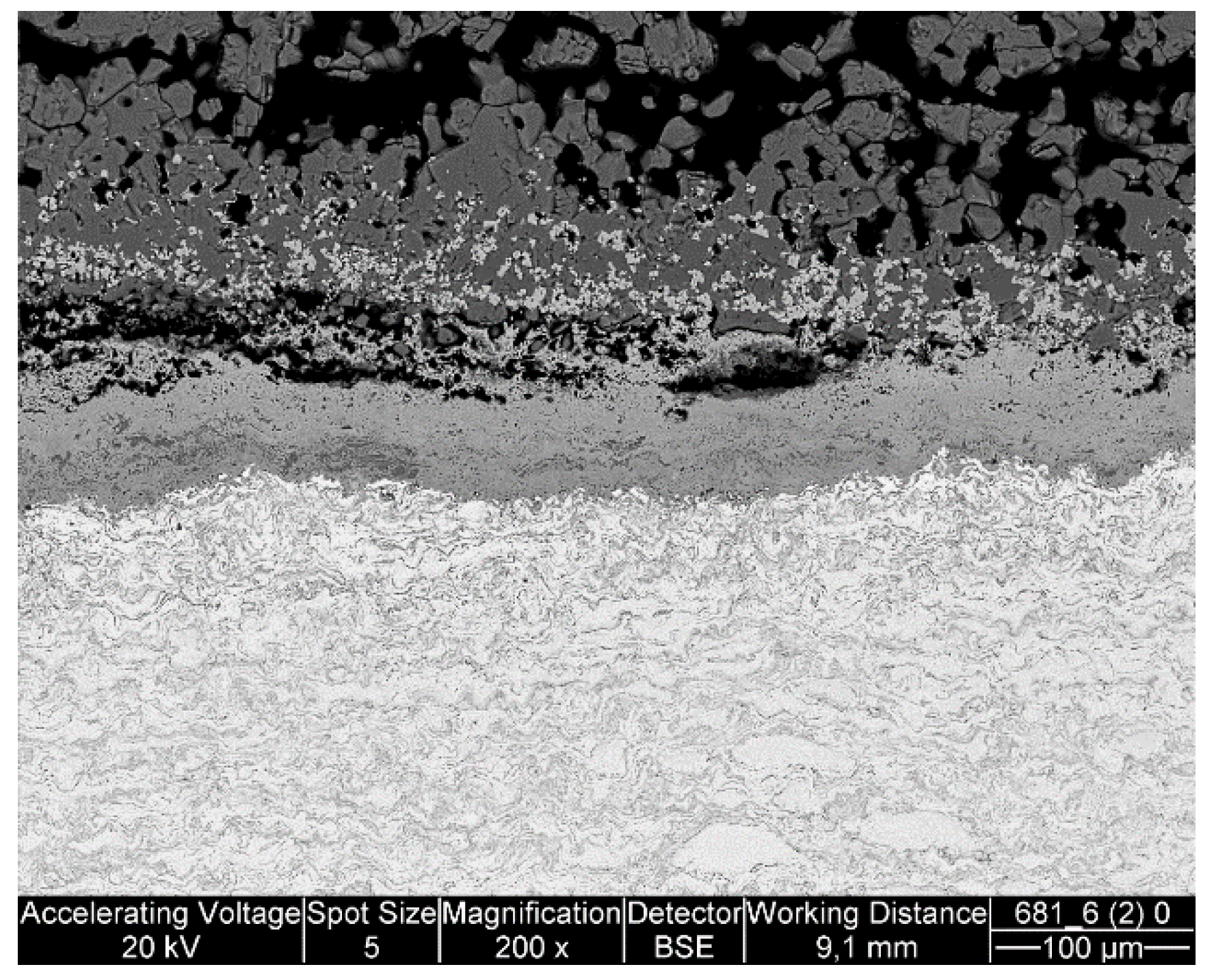
4. Discussion
As expected, the results showed that a higher temperature yielded higher amounts of corrosion. The corrosion mechanism appeared to be the same in both temperatures: sulfidation, possibly preceded by chlorine corrosion. The formation of such types of corrosion products cause by chlorine corrosion have also been reported by Oksa
et al. [
17]. Alkali chlorides in deposits may cause accelerated corrosion well below the melting point of KCl [
18]. Gases containing HCl for example, can influence the corrosion caused by other mechanisms, such as sulfidation, by breaking down the protective oxides and allowing corrosive species to reach the metal surface [
18]. Similar results have been reported by Haanappel
et al. [
19], who found that HCl in an oxidizing-sulfidizing environment increased the corrosion rate significantly and made the scales thick, porous and non-protective, comparable to the results of this study.
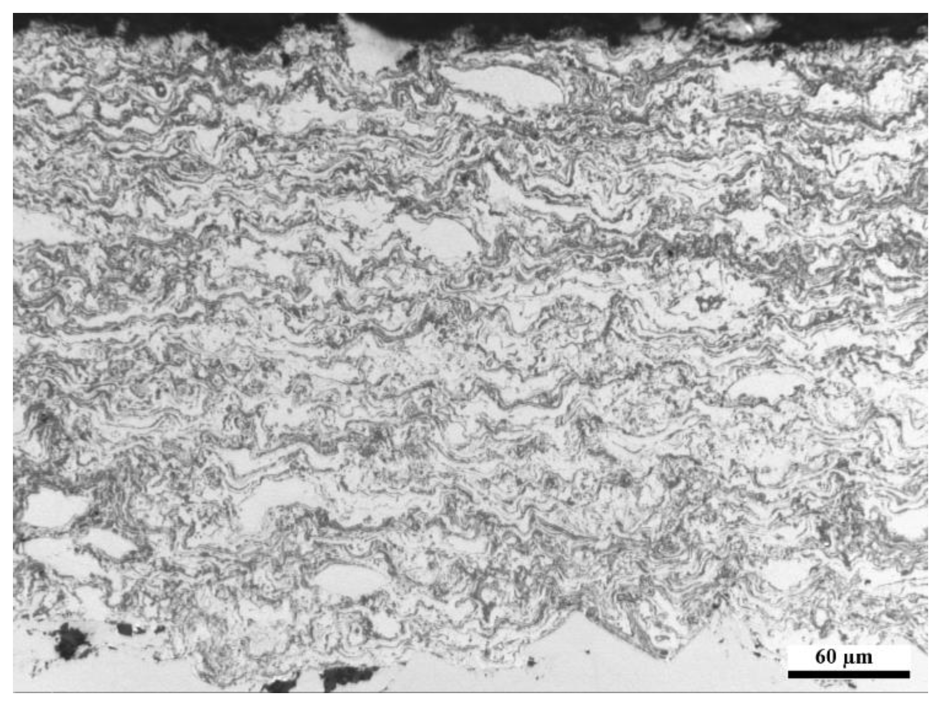
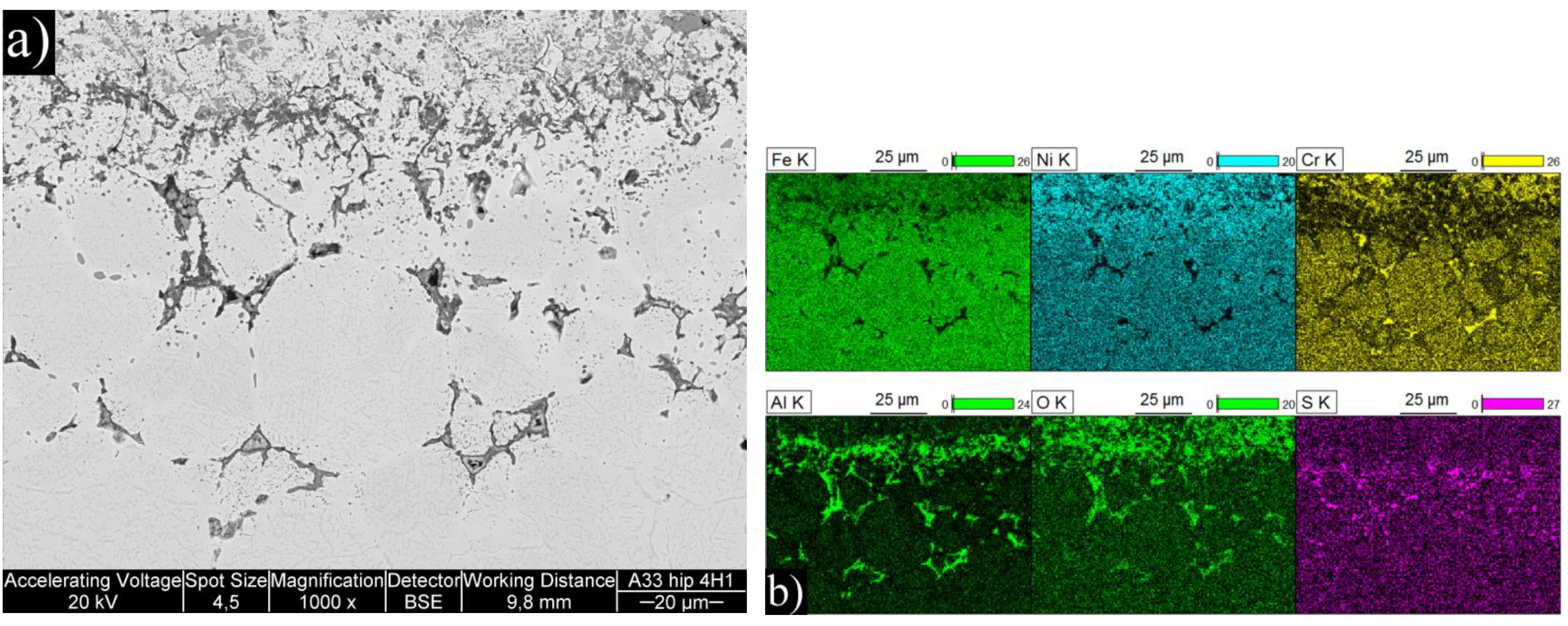
The manufactured FeNiCrAl composition was both thermal sprayed and HIP’ed so that the effect of microstructure to the performance could be seen. The structure of the DJ Hybrid coating showed some large splats, which were nicely deformed, and some completely oxidized small particles. The coating could have been improved by using a tighter powder fraction, either by removing the smallest particles and using current spray parameters, or by removing the largest particles and using cooler spray parameters. The over-oxidized lamellae boundaries in the coating could have contained porosity or might have micro-cracked under thermal stress and therefore allow faster diffusion of corrosive species into the coating and enabled diffusion of coating element outward, as Ni and Fe were found diffused deep into the deposits. Having small lamellas lead to an increased amount of lamellae boundaries and hence higher diffusion when the boundaries act as diffusion paths. Aluminum did not effectively block the lamellae boundaries, and XRD results showed that the predicted phases did not form. This was likely due to the composition mismatch between the calculated and manufactured powder. Based on the EDX results of
Table 3, there is room for optimization in the powder manufacturing, because the actual composition had 17% less Ni and 7% less Cr than planned. Al content was exactly as planned. Unfortunately, the HIP’ed specimen had large porosity between the particles, making it more difficult to compare with the other specimens as intended. However, the larger particles do show how the corrosive species diffused inside the particles through grain boundaries. The same was observed on a smaller scale in the coatings.
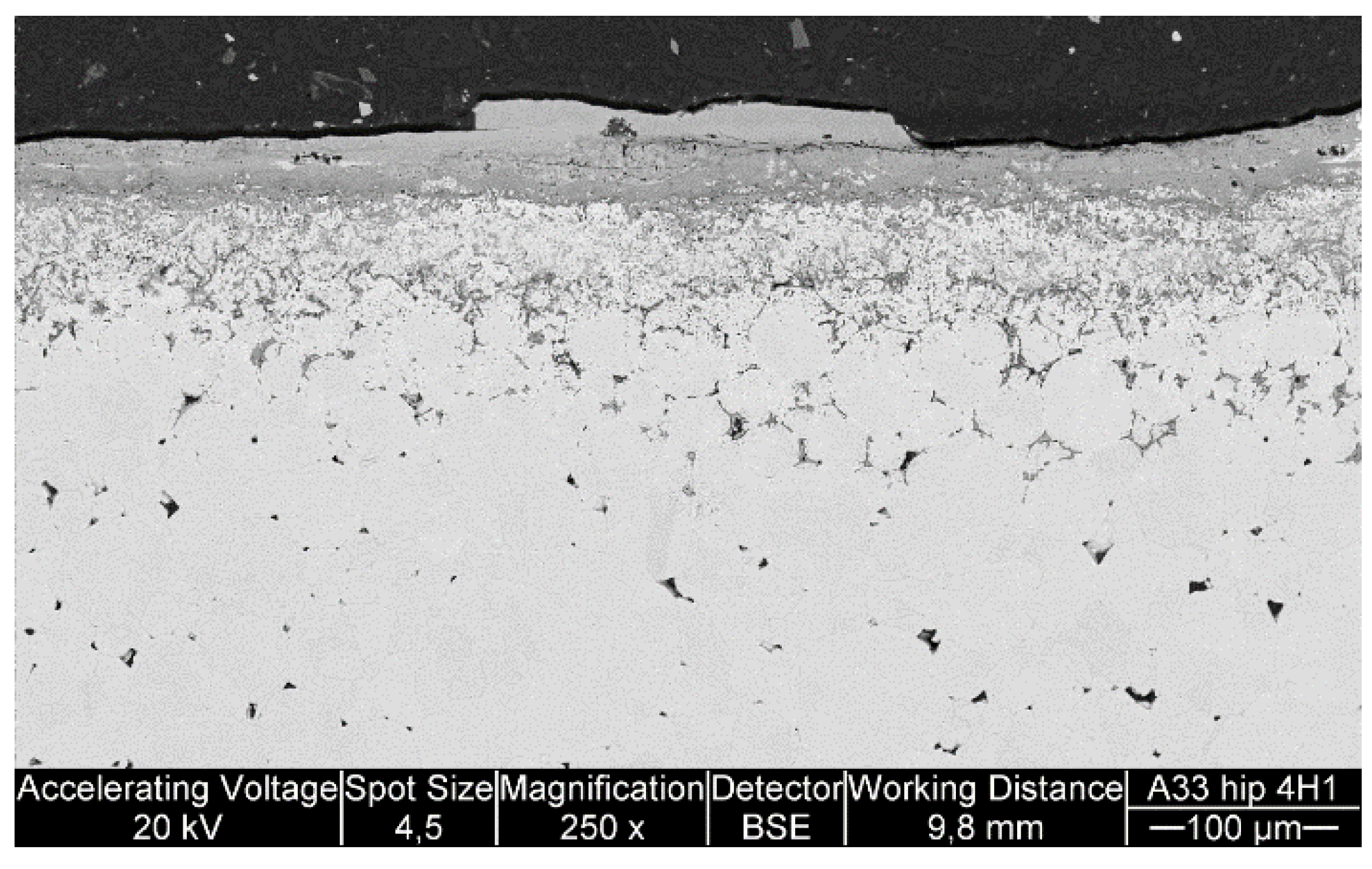
The exposure tests were conducted on single specimens, so the approach is guiding rather than statistical. TP347HFG performed well at 650 °C by having the second thinnest corrosion products (100 + 30 μm), being only slightly behind the HVOF coating, which would have had 86 + 29 μm if we assume linear growth from 700 h exposure to 1000 h. At 720 °C the oxide had spalled, but based on the amount of internal corrosion, the material could be the best performer of the experiment. The reference material Sanicro 25 had disastrous performance at both temperatures, even though it contained more Cr (22.5
vs. 18 wt %) and Ni (25
vs. 11 wt %) than the TP347HFG. Selective corrosion of Cr has been observed to increase in Cl containing atmospheres when Cr content increases [
20]. However, the Cr difference of TP347HFG and Sanicro 25 is quite small compared to the performance difference. Therefore, the very poor performance of Sanicro 25 steel was more likely related to its Cu content.
When present in deposits, copper has been found to increase corrosion rates significantly in chlorine containing conditions by catalyzing the formation of elemental chlorine from HCl [
21,
22]. Because chemical composition of Sanicro 25 with higher Cr and Ni content would suggest that the material had better corrosion resistance than TP347HFG, we suggest that copper has probably had an influence on the high corrosion rate as an alloying element. Together with preferential removal of Cr at the corrosion front, copper may have reacted with chlorine and contributed to the very high corrosion rate of Sanicro 25. As a reference, TP347HFG and SAN25 have been tested in air- and oxy-firing conditions by Holcomb
et al. [
13]. The corrosion rates varied from 0–25 nm/h at 550 °C to 210–615 nm/h at corrosion peak temperature of about 700 °C, when chlorine was not present in the deposit.


