Article

Light-Field Optimization of Deep-Ultraviolet LED Modules for Efficient Microbial Inactivation

1
Engineering Research Center of Micro-Nano Optoelectronic Materials and Devices, Ministry of Education, Fujian Key Laboratory of Semiconductor Materials and Applications, College of Physical Science and Technology, Pen-Tung Sah Institute of Micro-Nano Science and Technology, Tan Kah Kee Innovation Laboratory (FDIX), College of Chemistry and Chemical Engineering, Xiamen University, Xiamen 361005, China
2
Xiamen Intelligent Health Research Institute, Xiamen 361009, China
*
Authors to whom correspondence should be addressed.
Coatings 2024, 14(5), 568; https://doi.org/10.3390/coatings14050568
Submission received: 18 March 2024 / Revised: 24 April 2024 / Accepted: 30 April 2024 / Published: 3 May 2024

Abstract

:
Public awareness of preventing pathogenic microorganisms has significantly increased. Among numerous microbial prevention methods, the deep-ultraviolet (DUV) disinfection technology has received wide attention by using the nitride-based light-emitting diode (LED). However, the light extraction efficiency of DUV LEDs and the utilization rate of emitted DUV light are relatively low at the current stage. In this study, a light distribution design (referred to as the reflective system) was explored to enhance the utilization of emitted DUV from LEDs, leading to successful and efficient surface and air disinfection. Optical power measurements and microbial inactivation tests demonstrated an approximately 79% improvement in average radiation power density achieved by the reflective system when measured at a 5 cm distance from the irradiation surface. Moreover, a statistically significant enhancement in local surface disinfection was observed with low electric power consumption. The reflective system was integrated into an air purifier and underwent air disinfection testing, effectively disinfecting a 3 m3 space within ten minutes. Additionally, a fluorine resin film at the nanolevel was developed to protect the light module from oxidation, validated through a 1200 h accelerated aging test under humid conditions. This research offers valuable guidance for efficient and energy-saving DUV disinfection applications.

1. Introduction

Over the last two decades, there have been several instances of Public Health Emergency of International Concern (PHEIC) caused by viral infections, such as H1N1 influenza virus, Zaire Ebola virus, Zika virus, and the severe acute respiratory syn-drome coronavirus 2 (SARS-CoV-2) [1,2,3,4]. The majority of these viruses were transmitted by aerosols or direct inoculation from contact with infected surfaces, and they caused severe damage to the global economy and healthcare. To effectively reduce viral spread and bacterial reproduction, various disinfection approaches have been used, including ozone, chemical reagents, and ultraviolet (UV) [5]. While these approaches have proven effective in reducing microbial activity, it is crucial to acknowledge the potential drawbacks associated with certain disinfection agents. Notably, the approaches of ozone and chloric reagents might result in by-products and thus potential risks for the environment and human health. Consequently, it becomes imperative to strike a balance between the efficacy of the disinfection process and the potential adverse impacts on our surroundings and well-being. Striking this balance is essential to ensure that our endeavors to combat viral and bacterial threats do not inadvertently contribute to broader challenges in environmental sustainability and public health. Encouragingly, UV technology could be more eco-friendly thanks to the absence of by-products [6]. It has been reported that deep-ultraviolet (DUV), with a wavelength ranging from 200 nm to 280 nm, can be absorbed by microbial DNA and RNA. DUV radiation plays an important role in the disruption of genetic material. It can excite two adjacent thymine molecules in DNA or uracil molecules in RNA, causing the breakage of the hydrogen bonds between their original base pairs. This process results in the formation of thymine dimers or uracil dimers, respectively. The accumulation of such dimers can disrupt DNA/RNA replication, ultimately resulting in the inactivation of microorganisms [7]. It is reported that the DNA and RNA of microorganisms have an obvious peak absorption for UV ranging from 255 nm to 285 nm [8], making them more sensitive to absorbing UV photons. The DUV radiation dose for different microbial inactivation levels was widely investigated. In the case of SARS-CoV-2, it has been reported that ≥16.9 mJ/cm2 could completely inactivate the wildtype of SARS-CoV-2 at a multiplicity of infection (MOI) of 1000 [9]. Moreover, the mutations of SARS-CoV-2 (that is, Omicron) have significantly higher UV resistance and therefore require a higher UV radiation dose compared to the wildtype [10,11]. For effective and rapid disinfection against microorganisms, a DUV light source with high light output power, uniformity, and virucidal efficacy is indispensable. Currently, the light sources in the field of microbial inactivation include mercury lamps, excimer lamps, cathodoluminescent (CL) chips, and DUV light-emitting diodes (LEDs) [12]. Compared to traditional mercury lamps, DUV LEDs are chip-scale and have the advantages of narrow-band wavelength, eco-friendliness, high-speed switching capabilities, etc. [13]. It would be the trend in the future for a UV light source with outstanding scientific and practical values.
The DUV LEDs are mostly fabricated by aluminum gallium nitride (AlGaN) materials with quantum structure, and their performance could be evaluated by external quantum efficiency (EQE), light extraction efficiency (LEE), and wall-plug efficiency (WPE). However, the EQE and WPE of DUV LEDs still remain ≤10% due to current fabrication technology (around 40% for traditional blue light-emitting diodes) [14,15]. These parameters are closely related to the sealing material and electrode material. Meanwhile, the high aluminum composition in AlGaN quantum wells would result in a significant optical anisotropy and the subsequent high-portion transverse magnetic (TM) of the emitted light. This part of light tends to propagate laterally within the quantum wells and is hard to extract effectively for practical usage. Therefore, the low efficiency is mainly due to this part of lateral light loss [14]. Thus, related technological breakthroughs are required to face the challenges mentioned for improving the efficiency of DUV LED. Attempts such as the high-temperature annealing method in the material growth process and solid–liquid hybrid-state organic lenses in the packaging process have been investigated [16,17]. Nevertheless, the current performance of a single DUV LED chip on the irradiation area and uniformity still need a huge enhancement to meet the requirements in the practical application of disinfection.
Multi-LED chip integration with light distribution design is an expeditious method to form a large irradiation area with high uniformity. Liu et al. integrated DUV LEDs into an array to form a light module instead of a single chip, and this light module had an efficient inactivation result on SARS-CoV-2 [6]. With the integration of DUV LEDs, the electric energy consumption would increase. At the same time, the lateral light loss from each single LED chip would converge, resulting in much more optical power loss from the light module. Additionally, arranging LED chips together would not directly cause even DUV irradiation. For instance, the emission of LEDs follows a Lambertian emission pattern. The light output power (LOP) might be different between the central and edge of LED chips, thus requiring a light distribution design to optimize uniformity. The integration of multiple LEDs has not changed the irradiation distribution trend of the LEDs. A significant portion of ultraviolet energy fails to concentrate in the direct irradiation area of the light source. Therefore, optimized DUV disinfection by light distribution design is vital for improving optical efficiency and saving energy [18].
In this work, an optimized reflective system for a multi-chip DUV light module was designed. Comprehensive optical simulations and optical power tests were conducted to evaluate the efficiency and reliability of the optimized reflective system compared to those without the system. Subsequently, DUV disinfection tests for two different microorganisms were carried out on the local surface and in the air. Ultimately, a protective film was involved to extend the life span of the optimized reflective system, and its protection ability was confirmed by accelerated aging.

2. Materials and Methods

The optical simulations were conducted using the Monte Carlo ray-tracing method [19]. The DUV LED light module was constructed with 64 DUV LEDs with a 275 nm wavelength, arranged in an 8 × 8 matrix with an arrangement period of 13.5 mm (Figure 1). The LED chips (3.5 mm × 3.5 mm × 1.47 mm for length, width, and height, respectively) comprised n-AlGaN, multi-quantum wells, p-AlGaN, and sapphire substrates. A reflective system (12 cm × 12 cm for length and width, made of aluminum) was studied and designed to enhance the light efficiency. There were 64 designed structures in the reflective system, and the internal sidewall of each designed structure could have an influence on light efficiency enhancement. Before the optical simulations, a preliminary test was conducted to determine the basic structural parameters of the reflective system. The surface reflectance of the sidewall was set to 90% at the 275 nm wavelength, corresponding to the reflectance of aluminum [20]. A 10 cm × 10 cm planar surface was used to receive the UV irradiation, and the distance between the light module and this surface was set to 10 cm. The optical power of each LED was set to 50 mW, and the combinations between different incline angles and radii were investigated. Then, the light attenuation at different distances was investigated. The light module without the designed reflective system was defined as ‘Control’ in this study.
To assess the optical performance of the fabricated DUV light module with and without the designed reflective system, optical power and far-field distribution were measured by an optoelectronic analyzer (THORLABS PM100D). The aluminum reflective system was manufactured by precision machining. The internal sidewalls of the designed structures in the reflective system were mechanically polished to achieve high reflectivity. Additionally, DUV LEDs with a typical flip–chip structure would cause uneven thermal conduction, resulting in a poor thermal dissipation effect [21]. A thermal dissipation structure (such as air or water cooling) could be a solution to address this issue. Thus, a water-cooling system was installed to improve the thermal dissipation, and this cooling system started to work when the temperature of the module was above 28 °C, preventing the damage from overheating (Figure 2a). The material of the connection between the LED chip board and the water-cooling system was silicon grease, thanks to its great thermal conductivity. The optical power of the DUV light module was regulated by changing the electrical power. During the measurement, the distance between the light module and the optoelectronic analyzer was set to 5 cm based on the optical simulation result, and an irradiation area of 10 cm × 10 cm was monitored.
The microbial-inactivation experiments were carried out by the Guangdong Institute of Microbiology (Guangzhou, China), and the inactivation effect of the DUV light module has been evaluated subsequently. The standards and methods of testing were based on the Technical Standard for Disinfection (Ministry of Health, Edition 2002), Section 2 (2.1.5.4) [22]. The test temperature was 23 °C, and the distance between the light module and microorganisms was 5 cm. Staphylococcus aureus (ATCC 6538) was used as the test microorganism under different test conditions (20, 40, 60, 80, and 100% of the electrical power of the light module). The DUV irradiation time could be precisely controlled by a digital timer (one or two seconds were set in this study). The average colony-forming units (CFU) of positive controls and testing groups were recorded, and the killing log value and killing rate of organisms were calculated. The killing log refers to the difference in the 10-based logarithmic count of colonies after disinfection compared to that of the untreated group.
Furthermore, an air fan and the light module, along with the reflective system, were used to form an air purifier with a flowing rate of 200 m3 per hour. Subsequently, an air disinfection test at room temperature was carried out by the Xiamen Intelligent Health Research Institute. A three-cubic-meter test room (about 1.25 m × 1.25 m × 2 m for the length, width, and height, respectively) was used to examine the treatments. E. coli was used and cultivated in the Luria Broth nutrient agar. Before the DUV disinfection, the E. coli solution was sprayed by the TK-3 microbial aerogel generator at a concentration of about 106 CFU/mL, followed by a 5 min circulation and a 5 min settle down. During the DUV disinfection of air, 40% of the electrical power of the light module was set, and a series of irradiation times (5, 10, 15, 20, and 30 min, respectively) was investigated. After that, the purified air was collected by a six-stage sieve impact air microbiological sampler (FA-1) placed at the center of the test room with a one-meter height. This air collection was conducted at a flow rate of 28.3 L/min for 3 min for each treatment. Then, the collected samples were subsequently incubated at 37 °C for 24 h prior to the CFU calculation. The calculation results eliminated the influence of natural death factors on microorganisms in the air. It could be demonstrated by the following formula:
N t ( % ) = V o V t V o × 100
where Nt is the natural death rate, Vo is the bacterial content of the air before the test of the control group, and Vt is the bacterial content of the air after the test of the control group. The microbial disinfection rate could be calculated using the following formula:
K t ( % ) = V 1 × ( 1 N t ) V 2 V 1 × ( 1 N t ) × 100
where V1 is the bacterial content of the air before the test of the experimental group and V2 is the bacterial content of the air after the test of the experimental group. All DUV disinfection tests for surface and air were performed in triplicate, and the significant differences were analyzed by t-tests using GraphPad Prism.
The material aluminum was used to construct the reflective system, but this material is easy to oxidize and corrode in an atmospheric environment. Thus, a fluorine resin (T6, provided by Shanghai FluoroLuster Materials Co., Ltd. (Shanghai, China), with a refractive index of 1.34 under the DUV region) was selected to make a protective film protecting potential oxidation and corrosion of aluminum material, and an accelerated aging test was conducted to examine its ability subsequently.
Before the accelerated aging test, two groups (protected and non-protected) with six pieces of quartz sheet (the size of each quartz sheet was 2.0 cm × 2.0 cm × 0.1 cm) were set, and one side of each piece was coated with a 200 nm aluminum layer by magnetron sputtering. The fluorine resin was dissolved in the ether solution and coated on the aluminum-containing surface of each quartz sheet by spinning coating. Then, the ether solution was volatilized by heating at 120 °C for one hour, resulting in a protective film with a thickness of about 200~500 nm. All samples were placed at a humidity of 88% and a temperature of 297 K for the accelerated aging test. The reflectivity of each sample was measured by a spectrometer (Lambda 850) provided by PerkinElmer Inc. (Waltham, MA, United States), and all measurements were calibrated with the standard aluminum mirror (Φ38 mm, provided by Guangzhou Jingyi Optoelectronic Technology Co., Ltd. (Guangzhou, China)).
The data from the disinfection on local surfaces were analyzed by the t-test method. The data from the disinfection on air were analyzed by a one-way analysis of variance (ANOVA) at an alpha level (α) of 5%, and significantly different parameters were further analyzed with Fisher’s least significant difference (LSD).

3. Results

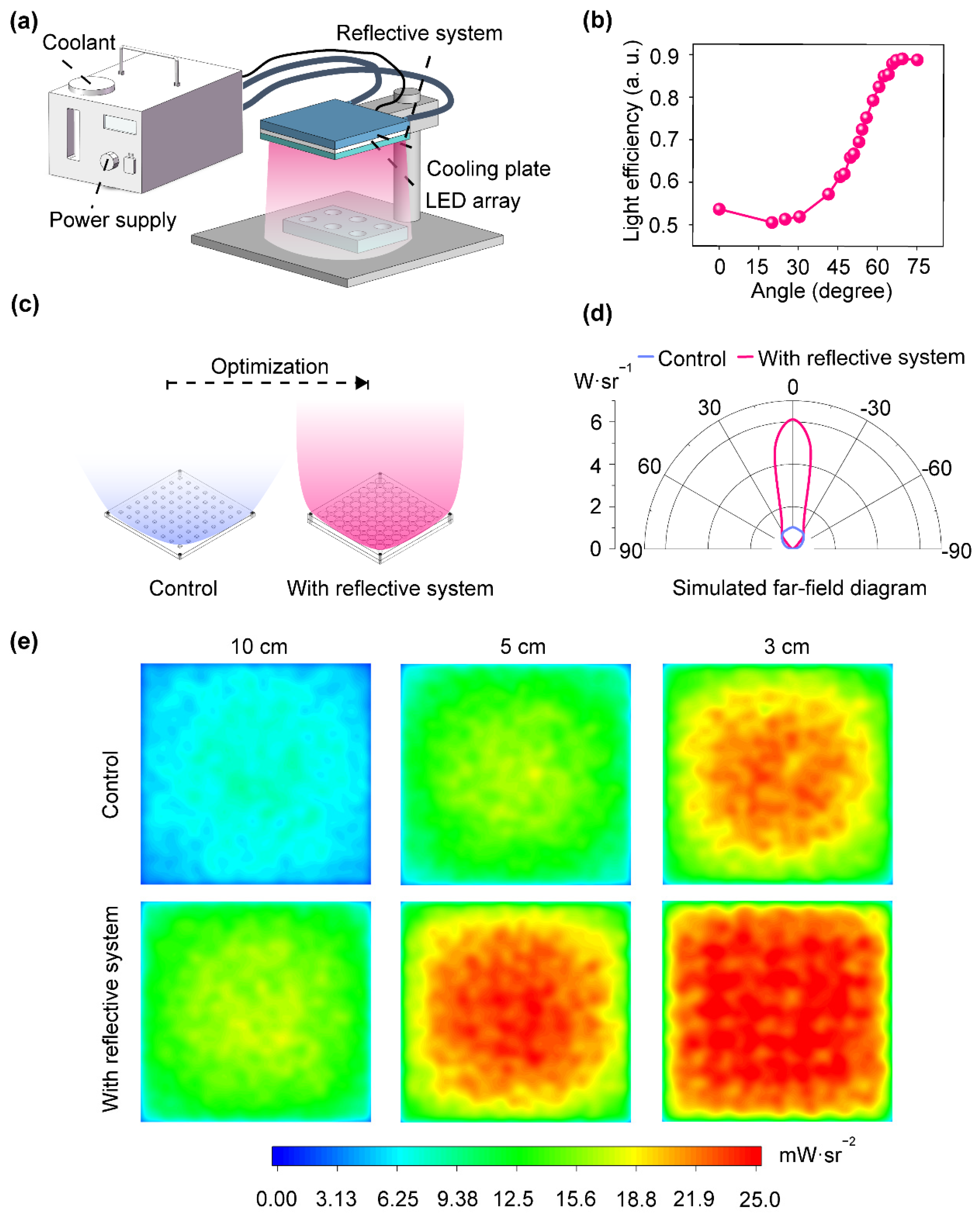
3.1. Preliminary Test

The structures of the DUV light module and the reflective system are shown in Figure 1. The designed structure in the reflective system was intended to modify the pathway of the laterally emitted DUV, and the incline angle of the designed structure had a significant influence on this modification. Thus, the degrees of the incline angle (that is, the θ in Figure 1) ranging from 0° to 75° were investigated in a preliminary test. The schematic diagram of the DUV light module used for the preliminary test and subsequent optical simulations is shown in Figure 2a. A huge enhancement of the light efficiency (defined as the ratio of the UV radiation intensity over the module’s projection area to the total radiation intensity of the light source) for the DUV module was obtained on the receiving surface when the angle ranged from 60° to 75° (Figure 2b). Therefore, the bottom radius of the designed structure was set to 2.6 mm, and the top radius was set to 6 mm with a height of 7 mm (this resulted in θ = 64.09°, and this angle was applied in the reflective system shown in Figure 2c). Additionally, the emitted light from the module could be dramatically concentrated from both the intensity and divergence angle aspects (Figure 2d). This might minimize the lateral power loss, ultimately leading to an enhancement in efficiency.

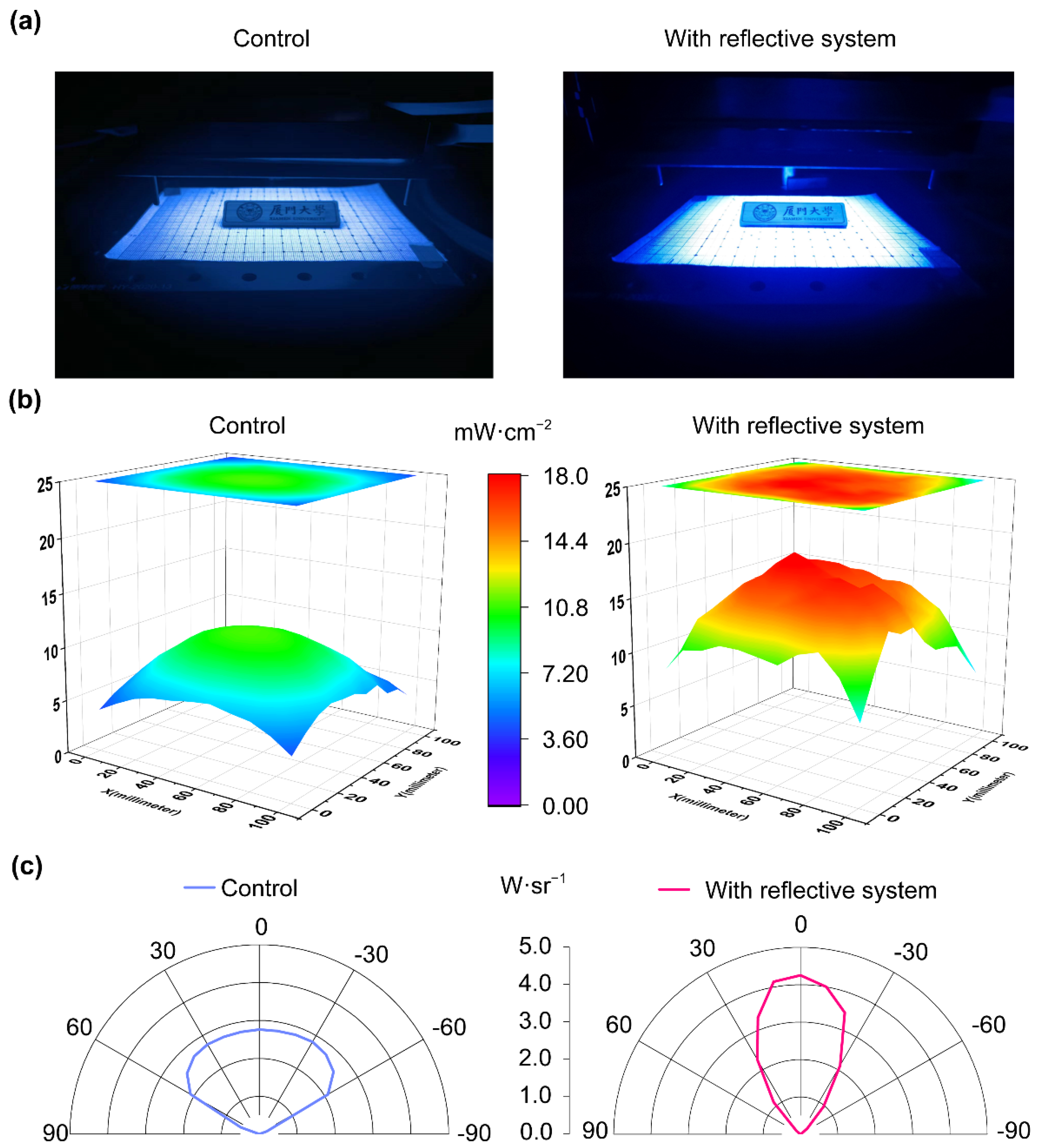
3.2. Optical Simulation and Measurement

In the optical simulation, a significant enhancement in optical power density and uniformity was obtained thanks to the light distribution design. The enhanced optical power density was able to reach averages of 21.50, 19.02, and 13.43 mW/cm2 at different distances of 3, 5, and 10 cm, respectively, in comparison with 17.36, 12.52, and 6.15 mW/cm2 for the control structure (Figure 2e). At a distance of 5 cm, the average radiation power density of the DUV light module with reflective system was 51.2% higher than the control. Similarly, at a 3 cm distance, the DUV light module with a reflection system demonstrated an average radiation power density 23.7% higher than the control. This indicated that at the irradiation distance commonly used for conventional sterilization applications, the reflective system significantly enhanced the utilization of the DUV energy, thereby improving the efficiency and reliability of the sterilization process.
The actual optical power and divergence angle of the fabricated light module were measured (Figure 3). Thanks to the optimization of the reflective system, the average optical power was improved from 7.87 mW/cm2 to 14.07 mW/cm2, and the peak intensity increased from 11 mW/cm2 to 18.8 mW/cm2. The average radiation power density had approximately a 79% improvement by optical measurement at a distance of 5 cm. In addition, the divergence angle was reduced from 120° to approximately 60°, resulting in a substantial reduction in lateral optical power loss. This indicated that the reflective system could effectively optimize the DUV light module and thus contribute to a high optical power density, and it might positively contribute to microbial inactivation. In addition, an irradiance intensity and relative driving power comparison was conducted to verify the profitability of the reflective system (Table 1). The findings indicate that the UV irradiance intensity of the reflective system doubled while maintaining the same electrical power as the control system. The control system, on the other hand, required an extra 50 W of electrical power to achieve the equivalent UV irradiance as the reflective system, effectively doubling the overall electrical power required.

3.3. Microbial Inactivation Test

The inactivation result (the reduction of ATCC 6538) on the local surface is shown in Figure 4. The average killing rate improved from approximately 95.8% to 97.3% when the test condition was 20% of the electric power, and the killing rate was over 99.99% when the electric power was greater than 40% of full power. There was no statistically significant difference between the positive control and the testing group. In addition, a killing log of approximately 4.9 was obtained under the condition of full electric power after 2 s of radiation, and the average CFU was reduced to below 40%. It could be demonstrated that the reflective system-optimized DUV light module could significantly and rapidly inactivate microorganisms on local surfaces with great reliability.
The schematic diagram of the air disinfecting test room is shown in Figure 5a. The DUV light module effectively inactivated the E. coli in the air flow passing through the purifier (Figure 5b). A disinfecting rate over 90% was obtained after ten-minute treatment of the DUV light module, and the disinfecting killing log was able to reach 1.4. The disinfecting rate became saturated when the irradiation time was extended to thirty minutes. In other words, a space of three cubic meters could be effectively disinfected within ten minutes (0.3 cubic-meter effective disinfection per minute) (Figure 5c). It demonstrated that the optimized DUV light module was efficient in the inactivation of bacteria. Thus, it could play a significant role in air disinfection, and it could effectively save electric energy or minimize the time needed for inactivation compared to the traditional DUV light module to achieve the same inactivation performance. This is of significant importance for improving the efficiency of preventing the spread of pathogenic microorganisms in indoor environments, and it could ultimately create a healthier living environment.

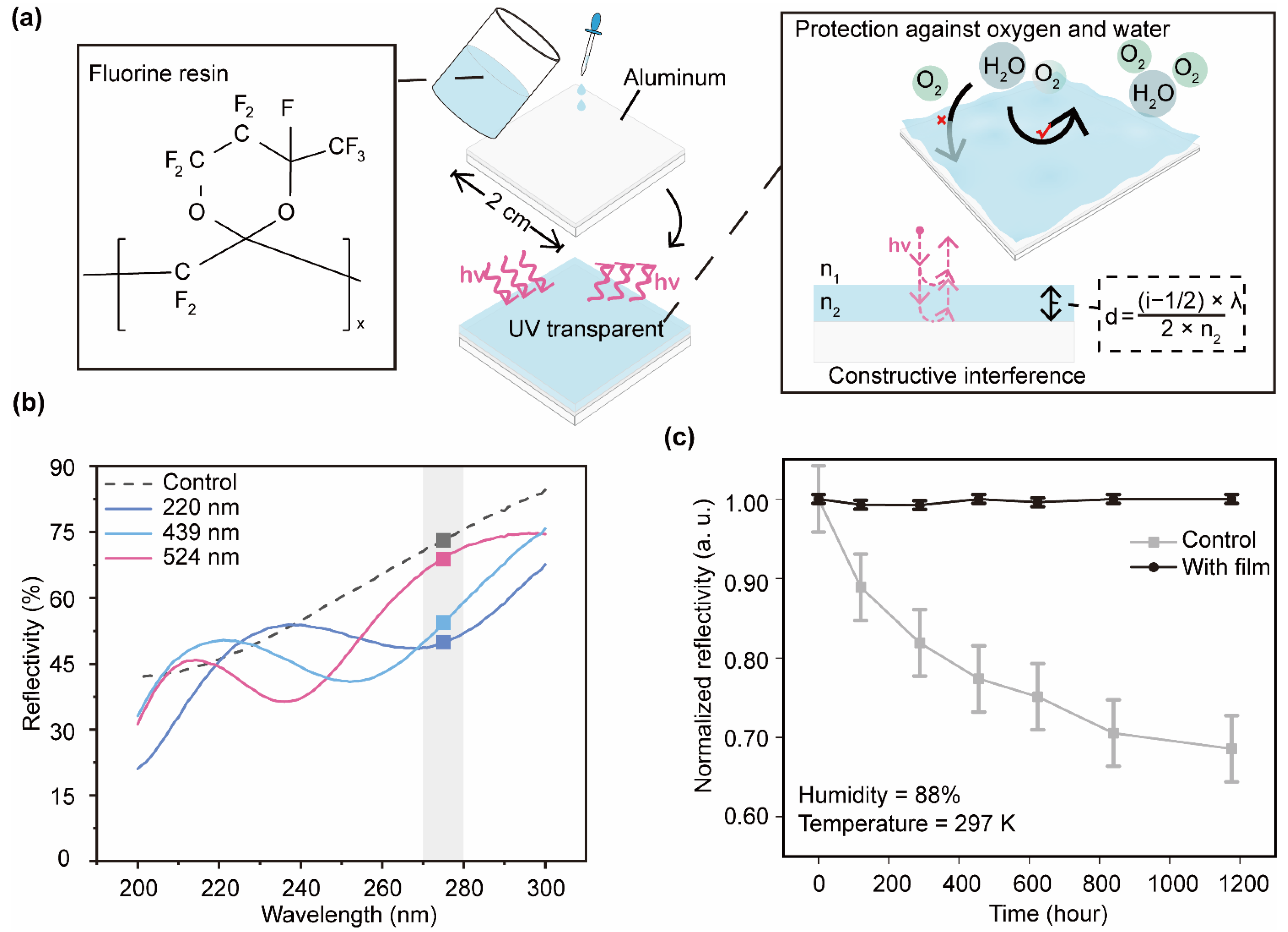
3.4. Fabrication and Verification of the Protective Film

The reflective system was made of aluminum, and this material is easy to oxidize and corrode in an atmospheric environment. Therefore, a nanolevel fluorine resin film was created in this study. Fluorine resin was selected because it has a relatively high transmittance within the entire DUV region and great thermal and UV resistance [23]. The chemical structure of the fluorine resin and the preparation of the protective film are shown in Figure 6a. The protective film would cause interference phenomena due to its thin thickness, resulting in either constructive interference or destructive interference. Thus, the thickness of the films was measured before the accelerated aging test, and the interference effect was observed by the reflectivity test (Figure 6b). It is expected that the reflected UV would be enhanced or, at the very least, stay unchanged when it passed through the film. It depends on the refractive index of this fluorine resin and the thickness of the film. For simplicity, only the case of a light incident perpendicular to the film was considered. Thus, a protective film was constructed following the equation below:
2 × n 2 × d + λ 2 = i × λ   ( i = 0 ,   1 ,   2 )
where n2 is the refractive index of the fluorine resin, d is the thickness of the film, and λ is the wavelength of the incident light. Thus, a protective film with a thickness of 154 nm, 256 nm, 359 nm, 461 nm, and 564 nm, respectively, was theoretically ideal for avoiding UV absorption. In fact, the reflection and transmission of light between two media must be determined by the Fresnel equations:
r = n 1 n 2 n 1 + n 2
t = 2 n 1 n 1 + n 2
R = | r | 2
T = n 2 n 1 | t | 2
where r is the reflection coefficient, t is the transmission coefficient, R is the reflectance, and T is the transmittance.
In the accelerated aging test, the reflectivity of the aluminum surface of the non-protected group decreased dramatically compared to the protected group at a wavelength of 275 nm (Figure 6c). It decreased approximately 30% compared to its initial condition after around 1200 h, while the protected group stayed unchanged. Therefore, the fluorine resin demonstrated a great performance on anti-oxidation, and thus it could contribute to the aluminum-made reflective system’s ability to work in a humid environment with an extended lifespan.

4. Conclusions

This work developed a light-field optimization for DUV LEDs and its nanolevel fluorine resin protective film. This optimization was achieved by a reflective system and verified by optical measurements and multiple disinfection tests against pathogenic microorganisms in local surface and air scenarios. An approximately 79% improvement in the DUV power density was achieved by this reflective system measured at a distance of 5 cm. Subsequently, a high disinfection rate was achieved with local surface disinfection with low electric power consumption. It demonstrated that the same disinfecting effect could be obtained with less electric energy and time consumption, resulting in a significant improvement in efficiency. The reflective system was installed to make an air purifier to conduct an air disinfection, and a disinfecting rate of up to 95.9% was reached after ten minutes when using 40% of full electric power. It demonstrated that the reflective system-optimized UV light module could have great performance in both local surface and air disinfection with low electric energy consumption. Furthermore, a fluorine resin film was fabricated to protect the reflective system from being oxidized, and it was verified through an acceleration aging test. It prevented about 30% degradation of the reflectivity of aluminum material after around 1200 h. The optical design developed in this work effectively improved the utilization rate and reliability of the DUV light emitted from LEDs and therefore enhanced the disinfection performance in surface and air scenarios. This work held the promise of contributing to human society by achieving better and more energy-efficient effects in microbial prevention.

Author Contributions

Conceptualization, W.K. and J.Y.; methodology, J.H., W.K. and J.Y.; software, J.Y. and J.K.; validation, J.H., X.Y., W.L., K.C. and S.Q.; formal analysis, J.H. and Q.W.; investigation, J.H., Q.W., X.Y., W.L., K.C., S.Q., W.K. and J.Y.; resources, W.K., J.Y. and J.K.; data curation, J.H. and Q.W.; writing—original draft preparation, J.H.; writing—review and editing, W.K. and J.Y.; visualization, J.H., W.K. and J.Y.; supervision, J.Y. and J.K.; project administration, W.K. and J.Y.; funding acquisition, W.K., J.Y. and J.K. All authors have read and agreed to the published version of the manuscript.

Funding

This work was financially funded by the National Key R&D Program of China (2022YFB3605002) and the Key Scientific and Technological Program of Xiamen (3502Z20231016 and 3502Z20211002).

Institutional Review Board Statement

Not applicable.

Informed Consent Statement

Not applicable.

Data Availability Statement

The data are contained within this article.

Acknowledgments

The authors thank Yunyong Zhang at the College of Physical Science and Technology, Xiamen University, for his assistance with the optical measurements.

Conflicts of Interest

The authors declare no conflicts of interest.

References

  1. Clerck, H. Emergence of Zaire Ebola virus disease in Guinea. N. Engl. J. Med. 2014, 371, 1418–1425. [Google Scholar]
  2. Hayes, E.B. Zika virus outside Africa. Emerg. Infect. Dis. 2009, 15, 1347. [Google Scholar] [CrossRef] [PubMed]
  3. Wu, D.; Wu, T.; Liu, Q.; Yang, Z. The SARS-CoV-2 outbreak: What we know. Int. J. Infect. Dis. 2020, 94, 44–48. [Google Scholar] [CrossRef]
  4. Neumann, G.; Noda, T.; Kawaoka, Y. Emergence and pandemic potential of swine-origin H1N1 influenza virus. Nature 2009, 459, 931–939. [Google Scholar] [CrossRef]
  5. Patterson, E.I.; Prince, T.; Anderson, E.R.; Casas-Sanchez, A.; Smith, S.L.; Cansado-Utrilla, C.; Solomon, T.; Griffiths, M.J.; Acosta-Serrano, Á.; Turtle, L.; et al. Methods of inactivation of SARS-CoV-2 for downstream biological assays. J. Infect. Dis. 2020, 222, 1462–1467. [Google Scholar] [CrossRef]
  6. Liu, S.; Luo, W.; Li, D.; Yuan, Y.; Tong, W.; Kang, J.; Wang, Y.; Li, D.; Rong, X.; Wang, T.; et al. Sec-Eliminating the SARS-CoV-2 by AlGaN Based High Power Deep Ultraviolet Light Source. Adv. Funct. Mater. 2021, 31, 2008452. [Google Scholar] [CrossRef]
  7. Bolton, J.; Cotton, C. The Ultraviolet Disinfection Handbook; American Water Works Association: Denver, CO, USA, 2008; pp. 25–40. [Google Scholar]
  8. Raeiszadeh, M.; Adeli, B. A Critical Review on Ultraviolet Disinfection Systems against COVID-19 Outbreak: Applicability, Validation, and Safety Considerations. ACS Photonics 2020, 7, 2941–2951. [Google Scholar] [CrossRef] [PubMed]
  9. Biasin, M.; Bianco, A.; Pareschi, G.; Cavalleri, A.; Cavatorta, C.; Fenizia, C.; Galli, P.; Lessio, L.; Lualdi, M.; Tombetti, E. UV-C irradiation is highly effective in inactivating SARS-CoV-2 replication. Sci. Rep. 2021, 11, 6260. [Google Scholar] [CrossRef] [PubMed]
  10. Kang, W.; Zheng, J.; Huang, J.; Jiang, L.; Wang, Q.; Guo, Z.; Yin, J.; Deng, X.; Wang, Y.; Kang, J. Deep-ultraviolet photonics for the disinfection of SARS-CoV-2 and its variants (Delta and Omicron) in the cryogenic environment. Opto-Electron. Adv. 2023, 6, 220201. [Google Scholar] [CrossRef]
  11. Jiang, K.; Liang, S.; Sun, X.; Ben, J.; Qu, L.; Zhang, S.; Chen, Y.; Zheng, Y.; Lan, K.; Li, D. Rapid inactivation of human respiratory RNA viruses by deep ultraviolet irradiation from light-emitting diodes on a high-temperature-annealed AlN/Sapphire template. Opto-Electron. Adv. 2023, 6, 230004. [Google Scholar] [CrossRef]
  12. Sharma, V.K.; Demir, H.V. Bright Future of Deep-Ultraviolet Photonics: Emerging UVC Chip Scale Light-Source Technology Platforms, Benchmarking, Challenges, and Outlook for UV Disinfection. ACS Photonics 2022, 9, 1513–1521. [Google Scholar] [CrossRef]
  13. Chen, J.; Loeb, S.; Kim, J.-H. LED revolution: Fundamentals and prospects for UV disinfection applications. Environ. Sci. Water Res. Technol. 2017, 3, 188–202. [Google Scholar] [CrossRef]
  14. Kneissl, M.; Seong, T.-Y.; Han, J.; Amano, H. The emergence and prospects of deep-ultraviolet light-emitting diode technologies. Nat. Photonics 2019, 13, 233–244. [Google Scholar] [CrossRef]
  15. Li, J.; Gao, N.; Cai, D.; Lin, W.; Huang, K.; Li, S.; Kang, J. Multiple fields manipulation on nitride material structures in ultraviolet light-emitting diodes. Light Sci. Appl. 2021, 10, 129. [Google Scholar] [CrossRef] [PubMed]
  16. Hagedorn, S.; Walde, S.; Susilo, N.; Netzel, C.; Tillner, N.; Unger, R.-S.; Manley, P.; Ziffer, E.; Wernicke, T.; Becker, C.; et al. Improving AlN Crystal Quality and Strain Management on Nanopatterned Sapphire Substrates by High-Temperature Annealing for UVC Light-Emitting Diodes. Phys. Status Solidi A 2020, 217, 1900796. [Google Scholar] [CrossRef]
  17. Li, Z.; Li, J.; Deng, Z.; Qiu, Y.; Li, J.; Yuan, Y.; Xu, L.; Ding, X. Solid–Liquid Hybrid-State Organic Lens for Highly Efficient Deep Ultraviolet Light-Emitting Diodes. Adv. Photonics Res. 2022, 3, 2100211. [Google Scholar] [CrossRef]
  18. Guan, Z.; Liu, P.; Zhou, T.; Zhou, L.; Zhang, D.; Xie, Q.; Yu, Q.; He, Y.; Wang, S.; Wang, X.; et al. Study on the Light Field Regulation of UVC-LED Disinfection for Cold Chain Transportation. Appl. Sci. 2022, 12, 1285. [Google Scholar] [CrossRef]
  19. Disney, M.; Lewis, P.; North, P. Monte Carlo ray tracing in optical canopy reflectance modelling. Remote Sens. Rev. 2000, 18, 163–196. [Google Scholar] [CrossRef]
  20. Hass, G.; Waylonis, J.E. Optical constants and reflectance and transmittance of evaporated aluminum in the visible and ultraviolet. J. Opt. Soc. Am. 1961, 51, 719–722. [Google Scholar] [CrossRef]
  21. Shatalov, M.; Chitnis, A.; Yadav, P.; Hasan, F.; Khan, J.; Adivarahan, V.; Maruska, H.P.; Sun, W.H.; Khan, M.A. Thermal analysis of flip-chip packaged 280 nm nitride-based deep ultraviolet light-emitting diodes. Appl. Phys. Lett. 2005, 86, 201109. [Google Scholar] [CrossRef]
  22. Ministry of Health of the People’s Republic of China. The Ministry of Health’s Notice on the Issuance of the “Technical Standard for Disinfection” (2002 Edition). 2002. Available online: http://www.nhc.gov.cn/cms-search/xxgk/getManuscriptXxgk.htm?id=16508 (accessed on 3 March 2023). (In Chinese)
  23. Liang, S.; Sun, W. Recent Advances in Packaging Technologies of AlGaN-Based Deep Ultraviolet Light-Emitting Diodes. Adv. Mater. Technol. 2022, 7, 2101502. [Google Scholar] [CrossRef]
Figure 1. A schematic diagram of the DUV light module and the designed reflective system (highlighted by baby-blue).
Coatings 14 00568 g001
Figure 2. (a) Schematic diagram of the DUV light module, including the power supply, cooling system, DUV LED, and reflective system. (b) Light efficiencies changed with different incline angles (that is, the θ in Figure 1). (c) Schematic illustration of the optimization of the DUV light module by the reflective system. (d) Simulated far-field diagram with and without the reflective system. (e) Simulated UV irradiation distribution at different action distances (10 cm, 5 cm, and 3 cm).
Coatings 14 00568 g002
Figure 3. (a) Photo images of the DUV light modules without and with the reflective systems. (b) Irradiation intensities of the DUV light module measured at a distance of 5 cm. (c) Far-field light distribution is improved by the reflective systems.
Coatings 14 00568 g003
Figure 4. The killing rate of ATCC 6538 on the local surface is caused by different DUV irradiations at different electric powers of the light module. Symbol * denotes for a p-value < 0.05 from the t-test analysis (comparing killing rates with and without the reflective system), and ns means no significance.
Coatings 14 00568 g004
Figure 5. (a) A schematic diagram of the air disinfecting test. (b) Details of the air purifier installed with the DUV light module. (c) Killing rate (mean ± standard error) of the E. coli caused by different DUV irradiation times (all tests were conducted under 40% of the electric power). The symbol *** denotes a p-value < 0.001 from the ANOVA analysis, and ns means no significance.
Coatings 14 00568 g005
Figure 6. (a) The chemical structure of the fluorine resin used for protection and a schematic diagram of the fabrication of the protective film. (b) Interference caused by different thicknesses of the protective film in the DUV region. (c) The reflectivity of the coated aluminum layers with and without fluorine resin protection (mean ± standard error) changed with time under the accelerated-aging condition.
Coatings 14 00568 g006
Table 1. Irradiance intensity and relative driving power tests of the DUV light modules without and with reflective systems.
GroupDistance (cm)Irradiance (mW/cm2)Current (A)Voltage (V)Electrical Power (W)
Control101.77650.99641.82342
With reflective system103.85350.99641.82542
Control103.85082.12243.31992
Disclaimer/Publisher’s Note: The statements, opinions and data contained in all publications are solely those of the individual author(s) and contributor(s) and not of MDPI and/or the editor(s). MDPI and/or the editor(s) disclaim responsibility for any injury to people or property resulting from any ideas, methods, instructions or products referred to in the content.

