
Water Lubrication of Al-Cu Composites Reinforced by Nickel-Coated Si3N4 Particles


College of Mechanical & Electrical Engineering, Nanjing University of Aeronautics & Astronautics, Nanjing 210016, China
*
Author to whom correspondence should be addressed.
Coatings 2024, 14(2), 225; https://doi.org/10.3390/coatings14020225
Submission received: 25 January 2024
/
Revised: 6 February 2024
/
Accepted: 10 February 2024
/
Published: 14 February 2024
(This article belongs to the Special Issue Design, Preparation, and Thermocapillary Migration Behavior of Lubricating Materials)
Abstract
:Silicon nitride (Si3N4) particle-reinforced aluminum–copper (Al-Cu) alloy matrix composites have been prepared in our previous works and experimental result shows that they can be used as a new kind of water-lubricated materials. However, the wettability between Si3N4 ceramics and Al-Cu alloys is poor and the manufacturing process is usually carried out at a high temperature of 1100 °C. To overcome this shortcoming, a layer of nickel was deposited on the surface of Si3N4 particles, forming a core-shell structure. Thus, the interface bonding property between Si3N4 and Al-Cu alloy can be improved and the lower sintering temperature can be applied. Si3N4/Al-Cu alloy composites with different proportions of Ni-coated Si3N4 were fabricated by powder matrix metallurgy technology at 800 °C, and the water lubrication properties of the composite were investigated. The experimental results show that with the increase in the particle content (10 wt%–40 wt%), the microhardness of the composites increased first and then decreased, while the porosity increased continuously. A low friction coefficient (0.001–0.005) can be achieved for the composites with the lower particle content (10 wt%–20 wt%). The major wear mechanism changes from the mechanically dominated wear during the running-in process to the tribochemical wear at the low frictional stage.
1. Introduction
Water has the advantages of environmental friendliness, flame retardation and low cost. Water as a lubricant has been used for mechanical equipment wear reduction; hydraulic machinery has also reflected the superiority of water lubrication. Therefore, compared with oil lubrication, the application prospect of water as a lubricant is broader, and water lubrication materials have become a research hotspot. Metal and ceramic materials as commonly used materials for water lubrication still have more or less shortcomings. Therefore, the combination of metal and ceramics to prepare metal-based ceramic materials has great prospects.
Cermet composites are widely used for metal cutting, rock drilling, and metal forming tools. In general, these composites consist of ceramic particles bonded with a metal matrix. However, it is a great challenge to design and fabricate cermet composites [1,2,3] since metals contain metallic bonds while ceramics mainly comprise ionic and covalent bonds. To improve the interface bonding strength between ceramic particles and metal, the surface metallization of ceramic particles is an effective method [4,5,6,7,8]. When the surface of the particle is coated with a metal film forming a core-shell structure, the wettability between the metal matrix and particle will be improved. Thus, the bonding strength of sintered cermet composites may be enhanced naturally.
There are many ways to fabricate the core-shell structured ceramic particles and electroless plating is a relatively convenient process. Electroless plating (EP) is a non-galvanic type of chemical treatment in which metals are produced by the controlled chemical reduction of metal ions onto the catalytic surface [9,10,11]. By using electroless plating, the surface of ceramic particles can be coated with a layer of metal. It has been verified that the Cu-coated Al2O3, SiC, and Al2O3-SiC mixed particles may increase the wettability of metals and improve the interface bonding strength [12,13,14]. Hu et al. [12] deposited Cu-coated SiC and prepared Cu-based SiC composites with better wear resistance and interfacial bonding force. Wang et al. [13] studied the effect of the plating solution composition on Cu-coated Al2O3 composite particles. The results showed that the proportion of the plating solution components plays an important role in synthesizing the Al2O3/Cu composite powders. Khosroshahi et al. [14] found that the wettability of molten A356 alloy to the Cu-coated Al2O3-SiC mixed particles can be improved markedly, and the strength and microhardness of ceramic reinforced A356 composite was also enhanced as well.
Besides copper, particles coated with nickel were also studied widely. Leo’n et al. [15] studied the wettability influence of nickel-coated Al2O3 and SiC ceramics on aluminum. The results showed that the contact angle between the coated ceramic and aluminum reduces to about 12°. Kretz et al. [16] prepared the nickel coating on SiC particles and they found that the thickness, morphology and microstructure of the nickel coating were mainly controlled by the growth conditions. LÜ et al. [17] fabricated Ni-coated SiC particles and found that the interface bonding strength of modified SiC/Al composites was enhanced. In addition, studies [18,19] also showed that trace amounts of nickel are beneficial to the wear resistance, microhardness and impact toughness of the final metal matrix composites.
Previously, our group has studied the preparation and water lubrication performance of Al-Cu alloy-based Si3N4 composites. It was found that the proper content of Si3N4 particles can increase the microhardness of the composite with a low friction coefficient in water. During the friction process, the main wear mechanism shifts from mechanical wear at the running-in period to tribochemical wear [20]. In this paper, to increase the wettability between the Si3N4 and Al-Cu alloy, the surface of the Si3N4 particles was coated with nickel by using electroless plating. Thus, Ni-coated Si3N4 particles reinforced aluminum–copper alloy composites are expected to sinter at low temperatures. The effects of Si3N4 content on the structure, morphology, porosity and microhardness of the composite were investigated. More attention was paid to the tribological performance of the composite in water.
2. Materials and Methods
2.1. Preparation of Ni-Coated Si3N4 Particles by Electroless Plating
Herein, Si3N4 particles with an average size of 10 μm (Shanghai Chao Wei Nano Technology Limited Company, Shanghai, China) were used. To achieve the core-shell structure, electroless plating was applied to fabricate the Ni-coated Si3N4 particles. The process could be divided into five steps: cleaning, coarsening, sensitization, activation and electroless plating. First, the Si3N4 particles were placed in anhydrous ethanol for 10 min with ultrasonic cleaning. The cleaned Si3N4 particles were etched in HF acid (AR, ≥40%) for 30 min and cleaned with deionized water three times. After that, the Si3N4 particles were sensitized by SnCl2·2H2O solution (16 g/L) and activated by PdCl2 solution (0.25 g/L), respectively. Specific sensitization and activation processes can be found in Table 1. Finally, the activated Si3N4 particles were put in the plating solution and the composition of bath are shown in Table 2. After electroless plating, the treated Si3N4 particles were cleaned three times with deionized water and vacuum dried at 200 °C to remove hydrogen. The surface appearance and EDS analysis of particles were examined by cold field emission scanning electron microscopy (Regulus-8100, Hitachi, Japan), as can be seen in Figure 1.
The surface of raw Si3N4 particles is smooth and flat (seen in Figure 1a), while the surface of treated Si3N4 becomes rough and a layer of tiny particles is deposited (seen in Figure 1b). The EDS analysis shows that nickel element has been detected on the particle surface. It can be confirmed that these ceramic particles had been coated with nickel.
2.2. Preparation of Al-Cu Alloy Composites Reinforced by Ni-Coated Si3N4
Ni-coated Si3N4 reinforced Al-Cu alloy matrix composites were prepared by powder metallurgy technology. The specific content of the treated particles used is shown in Table 3. During the preparation process, Al-Cu alloy powder and Ni-coated Si3N4 particles were mixed by using a planetary ball mill with a rotation speed of 300 r/min (XGB04, Nanjing Bo Yun Tong Instrument Technology Limited Company, Nanjing, China). Then, the mixed powder was cold-extruded into a wafer with a radius of 15 mm by an electric powder pressing machine (DY-30T, Tianjin Keji High-tech Limited Company, Tianjin, China), with a pressure of 240 MPa and held for 5 min. After that, the pressed wafer was put into a high-temperature vacuum furnace (BR-1700A, Bona Hot Kiln in Zhengzhou, China) with a vacuum degree of 10−1 Pa and a sintering temperature of 800 °C. The specific sintering process can be found in the literature [20].
2.3. Friction and Wear Test in Water
The water lubrication behavior of Ni-coated Si3N4 reinforced Al-Cu alloy matrix composites was evaluated by using a ball-on-disk tribometer. A Si3N4 ball with a diameter of 8 mm (Vickers hardness 14 GPa, surface roughness about 120 nm) was used to slide against the wafers (S1–S4). Before the experiment, all the wafers were polished to a surface roughness of Ra 0.2 μm. Throughout the test, the contact between the wafer and the ball was completely submerged in deionized water (pure water after removing impurities in the form of ions). The applied load, sliding radius and sliding speed were 2 N, 8 mm and 0.168 m/s, respectively; the sliding time was 1200 min. To ensure reliability, each test was conducted three times. The worn surfaces were observed by an optics microscope (VHX-600E, Keyence, Japan) and a cold field emission scanning electron microscope. Besides, the wear scars on the ball and the wear tracks were also characterized by a 3D profilometer (Contour GT-K0, Bruker, Billerica, MA, USA). Figure 2 shows the cross-section of the wear track on the wafer. It can be seen that there exists an obvious groove area (Adown) and an upwarped area (Aup). The wear volume (Vd) was obtained by integrating the average cross-section area (A), which can be calculated as (Adown − Aup). The wear volume Vd of Ni-coated Si3N4 reinforced Al-Cu alloy matrix composites is calculated as follows:
where r is the radius of the wear track on the worn wafer.
The wear volume (Vb) of the sliding Si3N4 ball can be calculated by:
where , R is the radius of the ball and d is the diameter of the wear scar.
3. Results and Discussion
3.1. Effect of Particle Content on the Structure, Morphology, Porosity and Microhardness
The phase of the sintered wafer was determined by an X-ray diffractometer (D8 Advance A25, Bruker, USA) with Cu Ka radiation (k = 0.15404 nm) and the results are shown in Figure 3. It can be seen that Al, CuAl2, and the Si3N4 peaks are predominant in the Ni-coated Si3N4 reinforced Al-Cu alloy matrix composites. According to reference [21], when the content ratio of Al and Cu is 9:1, there will be α phase (Al) and θ phase (CuAl2), which is consistent with the XRD results. With the increase in Ni-coated Si3N4 content, the Si3N4 peak strengthened gradually. In addition, it was also found that no new products appeared, indicating that no chemical reaction occurred during the sintering process. Al-Cu alloy and Ni-coated Si3N4 were bonded together mainly by metal melting. There are two reasons for the appearance of Al2O3. One is the oxidation of Al during the ball milling, and the other is during the sintering process due to the low vacuum degree of the furnace.
The surface morphology of the wafers after polishing was observed by a laser confocal microscope (VK-X3000, Keyence, Japan); the final arithmetical mean height of area Sa values was the mean of nine areas taken evenly across the composite wafer surface, as shown in Figure 4. S1 and S2 wafers express a smooth surface, while the other two are rough with visible pits.
Based on the images in Figure 4, the porosity of the four wafers was obtained by using ImageJ software and the result is shown in Figure 5. It can be seen that with the increased content of Ni-coated Si3N4, the porosity of the wafer increases. The surface porosities of S1 and S2 wafers are about 2.034% and 5.751%, respectively. When the content of Ni-coated Si3N4 reaches 30 wt%, the porosity increases abruptly, which is more than two times the S2 wafer. As the content increases to 40 wt% (S4), the increment of the porosity tends to be gentle. As the content of Ni-coated Si3N4 increases, the bonding phase of the Al-Cu alloy reduces relatively, which is not conducive to filling in the space between the Ni-coated Si3N4 particles, resulting in the increment of the porosity.
Figure 6 presents the effect of the particle content on the microhardness. For each sample, 9 points are measured by a microhardness tester (VMH-002VMA, Lecia, Germany). The normal load of 0.2 kgf/cm2 was applied with a loading time of 10 s. It can be seen that with the increase in Ni-coated Si3N4 content, the microhardness first increases and then decreases. According to the phase structure analysis in Figure 3, Al-Cu alloy is used as the bonding phase, and a small amount of Ni-coated Si3N4 particles are used as the reinforcing phase. For the low particle content (S1 and S2), the microhardness increases with the increasing particle content, which can be attributed to the traditional dispersion-strengthening mechanism [22]. For the high particle content (S3 and S4), the porosity of wafers increases obviously. In addition, the reduced bonding phase of the Al-Cu alloy cannot package the high content of Ni-coated Si3N4 completely. As a result, the bonding strength decreases. Thus, the microhardness of the S3 and S4 wafers declines.
3.2. Water Lubrication Performance
Figure 7 shows the friction curves of the four wafers under water lubrication conditions. At the very beginning, all the samples present a high friction coefficient of about 0.7. After a period of running-in, the friction coefficient reduced gradually. After sliding in water for 300 min, the friction coefficient of S1 and S2 wafers reaches about 0.05. The friction coefficients of both S3 and S4 wafers show a decreasing trend with a large fluctuation. Only the friction coefficient of wafer S3 dropped below 0.1 after the 1200 min test and the value of the S4 wafer was still above 0.25.
Figure 8 shows the final morphologies of the four wafers and the corresponding Si3N4 ball. It can be observed that the wear track of S1–S4 wafers is relatively smooth in general. With the increase in the Ni-coated Si3N4 particles, the wear tracks of the four wafers become wider and deeper, especially for the S4 wafer. The wear scar on the Si3N4 ball changes from a circle to the final oval with the increment of the Ni-coated Si3N4 particle content in the S1–S4 wafers; the size of the scars enhances significantly.
According to Equations (1) and (2), the wear volumes of the S1–S4 wafers and the Si3N4 ball were calculated, as shown in Figure 9. The wear volume of the S1 and S2 wafers is close and the values are about 0.012–0.013 mm3, while that of the S3 and S4 wafers increases significantly, especially for that of the S4 wafer (0.838 mm3). The wear volume of the Si3N4 ball also increases continuously, but the difference is not significant. The porosity of the S1 and S2 wafers is much lower than that of the S3 and S4 wafers (Figure 5), and the microhardness of the S1 and S2 wafers is higher (Figure 6). Thus, the samples of the S1 and S2 wafers present a lower wear volume. The samples S3 and S4 show high friction coefficients during the whole test period, which means mechanical wear dominates the friction process. Therefore, the two samples express the higher wear volume.
3.3. Water Lubrication Mechanism for the Low Friction Coefficient
As shown in Figure 7, the water lubrication performance of the S2 wafer is the best. To further explore the mechanism of the low friction, the evolutions of the wear morphology, wear volume, contact pressure as well as electrical conductivity of the lubricant were studied at the different sliding stages (50 min, 100 min, 200 min and 400 min). As shown in Figure 10, there are obvious groove areas and side ridge areas on the wear tracks, which are caused by the plastic deformation and plowing action of the Si3N4 ball sliding on the surface of the S2 wafer [23,24]. As time prolongs, both the width and depth of the wear track increase gradually. Note, that the side ridge areas on the wear track of the S2 wafer are obvious after sliding for 50 min; the side ridge areas decrease with the increase in time. In addition, the diameter of the wear scar on the Si3N4 ball at the sliding time of 50 min was 1214.5 μm, and the value increased by about 200 μm at 100 min. After sliding for another 100 min, the diameter of the scar increased by about 200 μm. When the sliding time increases from 200 min to 400 min, the value of the diameter only increases by about 16 μm. It can be determined that the side ridge areas at the wear track of the S2 wafer are most likely to be flattened or worn down by the ever-growing Si3N4 ball wear plane. The wear between the S2 wafer and the Si3N4 ball is relatively severe within the first 100 min.
In order to further determine the wear form of the S2 wafer and Si3N4 ball in the severe wear stage, the surface morphology of the S2 wafer was observed after sliding for 50 min, as shown in Figure 11. The entire worn area (a) appears fish scaled. The fish scale plane (b) is smooth, and the other areas are obviously convex and uneven with small particles. EDS analysis of a single fish scale plane shows no presence of N element, which means no Si3N4 existence. It can be concluded that mechanical and tribochemical wear co-dominated at this stage, and an oxide lubrication layer was formed, according to the tribochemical wear mechanism reported by Tomizawa and Fischer [25].
According to the wear morphologies of the wafer and the Si3N4 ball in Figure 10, the wear volume of the Si3N4 ball and track of the wafer at different stages were calculated by using the Equations (1) and (2), as shown in Figure 12. Firstly, the wear volume curve of the Si3N4 ball rises first and then flattens. The wear volume of the Si3N4 ball increases to 0.0419 mm3 in the first 200 min, and the value only enhances by 0.007 mm3 during the following 1000 min. Combined with the tribological curve of the S2 wafer, the friction coefficient can reach 0.05 after sliding in water for 150 min. It indicates that the wear volume of the Si3N4 ball is very small.
While for the wafer, the volume of the side ridge areas increases only within the first 50 min. Since the wear volume of the Si3N4 ball is also the largest at this stage, the friction coefficient is high. This indicates that at this stage, Si3N4 balls are mainly abrasive wear. Therefore, the wear volume of Si3N4 balls is enhanced quickly. The wafer is mainly plastic deformation, resulting in a large amount of side ridge areas at the wear track to 0.0068 mm3, while the groove volume is very small at 0.0005 mm3. With sliding continuing, the wear between the wafer and the Si3N4 ball is mainly caused by the plastic deformation and removal of the wafer by the Si3N4 ball. The microhardness of the Si3N4 ball is far greater than that of the wafer, so the wear volume of the Si3N4 ball is very small. However, the side ridge volume of the wafer begins to decrease gradually, and the groove volume surges to 0.00683 mm3. After 100 min, the changes in the side ridge volume and groove volume at the wear tracks of the wafer gradually tend to be flat, indicating that the mechanical wear between the wafer and Si3N4 ball gradually decreased, and tribochemical wear played a major role. In particular, the friction coefficient decreases to about 0.05 after 200 min, and the groove volume of the wafer only increases by 0.0031 mm3 within 1000 min.
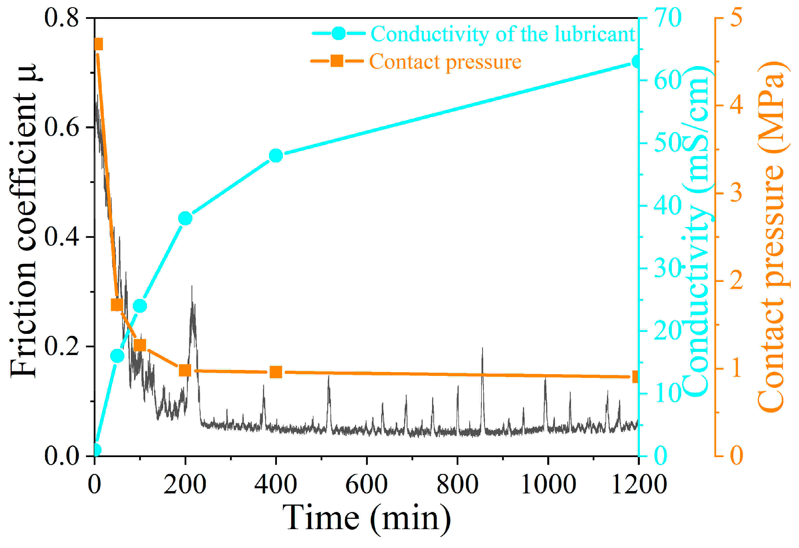
In addition, the contact pressure and the conductivity of the aqueous solution at different sliding times were also tested, as shown in Figure 13. It is well known that contact pressure is directly related to the friction. Therefore, the contact pressure between the wafer and the Si3N4 ball is roughly calculated according to the wear scar of the Si3N4 ball. According to Figure 13, it can be found that the whole friction process can be divided into two major stages: the surge stage (0–200 min) and the stabilization stage. In the surge stage, the contact pressure decreases gradually with the increment in the sliding time. The coefficient of friction at this stage also declined rapidly. While in the stabilizing stage, the value of contact pressure tends to be stable. In this state, the formation of the highly matched flat-on-flat geometry is essential for low friction. In addition, Xu et al. [26] found that tribochemical reactions can also be detected indirectly by monitoring the electrical conductivity of the aqueous solution. This value can be used to evaluate ion concentration and tribochemical reaction kinetics. It can be seen from Figure 13 that the conductivity value shows a gradually increasing trend, indicating the occurrence of tribochemical reactions. As mentioned in many reports [25], the chemical reactions consist of forming silicon oxide and silica gel, which may be written as
Si3N4 + 6H2O = 3SiO2 + 4NH3
SiO2 + 2H2O = Si(OH)4
It is believed that the formation of silica gel film between the tribo-pair can improve the lubricant viscosity as well as the load-bearing capacity. Thus, a low friction coefficient of 0.05 can be achieved.
4. Conclusions
In this paper, core-shell structured Si3N4 particles were successfully prepared, which may improve the wettability with the metal. Thus, the sintering temperature of the Ni-coated Si3N4 particle-reinforced Al-Cu alloy matrix composites can be reduced from 1100 °C to 800 °C. The microhardness of the composites increases first and then decreases. The highest value is 119 Hv for the S2 wafer with a particle content of 20 wt%. When the content of Ni-coated Si3N4 reaches 30 wt%, the porosity of the sample increases obviously. The wafers S1 and S2 with Ni-coated Si3N4 content of 10 wt% and 20 wt% present a low friction coefficient of about 0.005 in water. However, the friction coefficients of S3 and S4 wafers show a downward trend in the whole stage, and the value of the S3 wafer reduces below 0.1 after sliding in water for 1200 min. Since the S3 and S4 wafers have a lower microhardness and higher coefficient of friction, their wear volume reaches a high value of 0.838 mm3.
The water lubrication performance of the S2 wafer at different friction stages was studied. It is found that the wear mechanism of the S2 wafer is mainly from the initial abrasive wear dominated by plastic extrusion removal, and finally tribochemical wear.
Author Contributions
Conceptualization, Y.P. and W.H.; methodology, Y.P.; software, Y.P.; validation, Y.P., W.H. and Q.D.; formal analysis, Y.P.; investigation, Y.P.; resources, Y.P.; data curation, Y.P.; writing—original draft preparation, Y.P.; writing—review and editing, W.H and X.W.; visualization, Y.P.; supervision, W.H.; project administration, W.H.; funding acquisition, W.H. All authors have read and agreed to the published version of the manuscript.
Funding
This research was funded by the National Key Laboratory of Science and Technology on Helicopter Transmission (Grant No. HTL-A-22G14).
Institutional Review Board Statement
Not applicable.
Informed Consent Statement
Not applicable.
Data Availability Statement
The data presented in this study are available on request from the corresponding author.
Conflicts of Interest
The authors declare no conflicts of interest.
References
- Ramos-Masana, A.; Colominas, C. Evaluation of DC-MS and HiPIMS TiB2 and TaN coatings as diffusion barriers against molten aluminum: An insight into the wetting mechanism. Surf. Coat. Technol. 2019, 375, 171–181. [Google Scholar] [CrossRef]
- Pagounis, E.; Talvitie, M.; Lindroos, V.K. Influence of the metal/ceramic interface on the microstructure and mechanical properties of HIPed iron-based composites. Compos. Sci. Technol. 1996, 56, 1329–1337. [Google Scholar] [CrossRef]
- Ru, J.; He, H.; Wang, X.; Wei, S. Preparation and characterization of Ni-Cu dual coated ZTA particles by ionic liquid-assisted electroless plating as reinforcement of metalbased composites. Surf. Coat. Tech. 2020, 387, 125476. [Google Scholar] [CrossRef]
- Loto, C.A. Electroless nickel plating–A review. Silicon-Neth. 2016, 8, 177–186. [Google Scholar] [CrossRef]
- Ghosh, S. Electroless copper deposition: A critical review. Thin Solid. Film. 2019, 669, 641–658. [Google Scholar] [CrossRef]
- Kumar, K.; Bansal, V.; Sharma, S.; Kimothi, S.; Sharma, A. Microhardness and wear resistance of alkaline electroless Ni-P/Ni-P-ZnO nanocomposite platings. Mater. Today Proc. 2023, 80, 1219–1224. [Google Scholar] [CrossRef]
- Wang, S.; Sun, Y.; Li, G. Study on cobalt coating on ZTA particles by electroless plating and impact-abrasive wear behavior of ZTAp reinforced iron matrix composite. Wear 2022, 510–511, 204489. [Google Scholar] [CrossRef]
- Li, G.; Huang, X.; Guo, J. Fabrication of Ni-coated Al2O3 powders by the heterogeneous precipitation method. Mater. Res. Bull. 2001, 36, 1307–1315. [Google Scholar] [CrossRef]
- Dios, M.; Gonzalez, Z.; Gordo, E.; Ferrari, B. Chemical precipitation of nickel nanoparticles on Ti(C,N) suspensions focused on cermet processing. Int. J. Refract. Met. Hard Mater. 2017, 63, 2–8. [Google Scholar] [CrossRef]
- Zhang, Y.; Wang, W. A facile fabrication of Ag/SiC composite coating with high mechanical properties and corrosion resistance by electroless plating. Mater. Today Commun. 2023, 36, 106737. [Google Scholar] [CrossRef]
- Nguyen, D.H.; Kim, K.M.; Nguyen Vo, T.T.; Shim, G.H.; Kim, J.H.; Ahn, H.S. Improvement of thermal-hydraulic performance of plate heat exchanger by electroless nickel, copper and silver plating. Case Stud. Therm. Eng. 2021, 23, 100797. [Google Scholar] [CrossRef]
- Ming, H.; Yunlong, Z.; Lili, T.; Lin, S.; Jing, G.; Peiling, D. Surface modifying of SiC particles and performance analysis of SiCp/Cu composites. Appl. Surf. Sci. 2015, 332, 720–725. [Google Scholar] [CrossRef]
- Wang, H.; Jia, J.; Song, H.; Hu, X.; Sun, H.; Yang, D. The preparation of Cu-coated Al2O3 composite powders by electroless plating. Ceram. Int. 2011, 37, 2181–2184. [Google Scholar] [CrossRef]
- Beigi Khosroshahi, N.; Taherzadeh Mousavian, R.; Azari Khosroshahi, R.; Brabazon, D. Mechanical properties of rolled A356 based composites reinforced by Cu-coated bimodal ceramic particles. Mater. Des. 2015, 83, 678–688. [Google Scholar] [CrossRef]
- León, C.A.; Drew, R.A.L. The influence of nickel coating on the wettability of aluminum on ceramics. Compos. Part. A Appl. Sci. Manuf. 2002, 33, 1429–1432. [Google Scholar] [CrossRef]
- Kretz, F.; Gácsi, Z.; Kovács, J.; Pieczonka, T. The electroless deposition of nickel on SiC particles for aluminum matrix composites. Surf. Coat. Technol. 2004, 180–181, 575–579. [Google Scholar] [CrossRef]
- Lü, P.; Wang, X.; Dong, C.; Peng, C.; Wang, R. Preparation and characterization of different surface modified SiCp reinforced Al-matrix composites. J. Cent. South. Univ. 2020, 27, 2567–2577. [Google Scholar] [CrossRef]
- Kang, J.Y.; Heo, Y.U.; Kim, H.; Suh, D.W.; Son, D.; Lee, D.H.; Lee, T.H. Effect of copper addition on the characteristics of high-carbon and high-chromium steels. Mater. Sci. Eng. A 2014, 614, 36–44. [Google Scholar] [CrossRef]
- Li, T.Z.; Li, L.; Lu, H.; Parent, L.; Tian, H.; Chung, R.J.; Li, D.Y. Effect of trace Ni on the resistance of high-Cr cast iron to slurry erosion. Wear 2019, 426–427, 605–611. [Google Scholar] [CrossRef]
- Peng, Y.; Ma, C.; Dai, Q.; Huang, W.; Wang, X. Preparation and Water Lubrication Behaviors of Al-Cu Alloy-Based Si3N4 Composites. J. Mater. Eng. Perform. 2023, 1–11. [Google Scholar] [CrossRef]
- Ashkenazi, D. How aluminum changed the world: A metallurgical revolution through technological and cultural perspectives. Technol. Forecast. Soc. 2019, 143, 101–113. [Google Scholar] [CrossRef]
- Wang, S.; Xie, G.; Yang, J.; Liu, F.; Liu, X. Analysis of microstructure evolution and deformation mechanism of nano-oxides Al2O3 dispersion strengthened copper alloy during compression at room temperature. J. Alloy Compd. 2023, 949, 169837. [Google Scholar] [CrossRef]
- Chen, J.; Sun, T.; Su, J.; Li, J.; Zhou, P.; Peng, Y.; Zhu, Y. A novel agglomerated diamond abrasive with excellent micro-cutting and self-sharpening capabilities in fixed abrasive lapping processes. Wear 2021, 464–465, 203531. [Google Scholar] [CrossRef]
- Chen, J.; Zhu, N.; Niu, F.; Peng, Y.; Su, J.; Zhu, Y. Influence of agglomerated diamond abrasive wear on sapphire material removal behavior. Diam. Relat. Mater. 2020, 108, 107965. [Google Scholar] [CrossRef]
- Tomizawa, H.; Fischer, T.E. Friction and wear of silicon nitride and silicon Carbide in water: Hydrodynamic lubrication at low sliding speed obtained by tribochemical wear. ASLE Trans. 1987, 30, 41–46. [Google Scholar] [CrossRef]
- Xu, J.; Kato, K. Formation of tribochemical layer of ceramics sliding in water and its role for low friction. Wear 2000, 245, 61–75. [Google Scholar] [CrossRef]
Figure 1.
Surface morphology and EDS of Si3N4 particles, (a) raw Si3N4 particles; (b) treated Si3N4 particles.
Figure 1.
Surface morphology and EDS of Si3N4 particles, (a) raw Si3N4 particles; (b) treated Si3N4 particles.
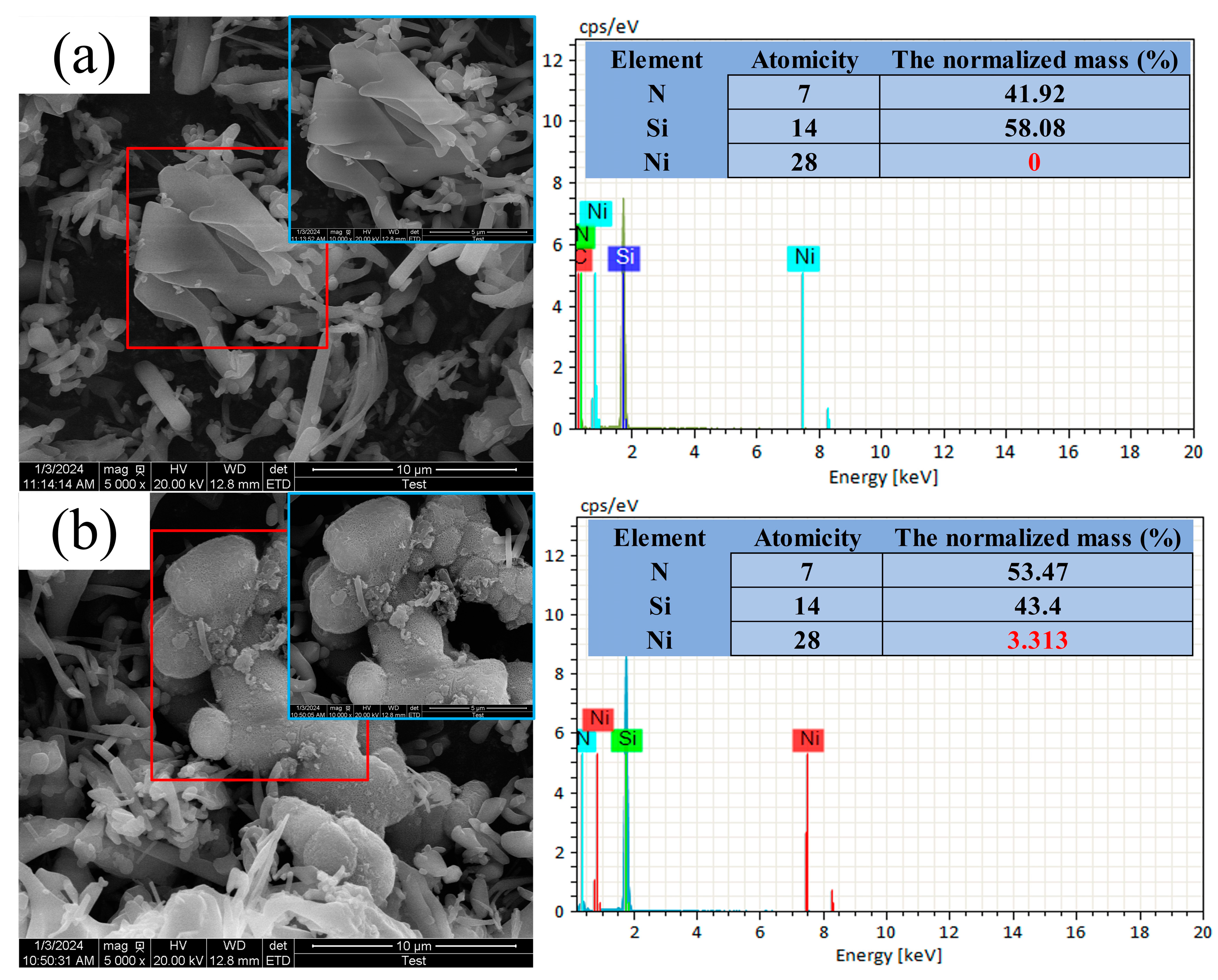
Figure 2.
The three-dimensional cross-section of the track on the wafer.

Figure 3.
XRD spectra of S1–S4 wafers.
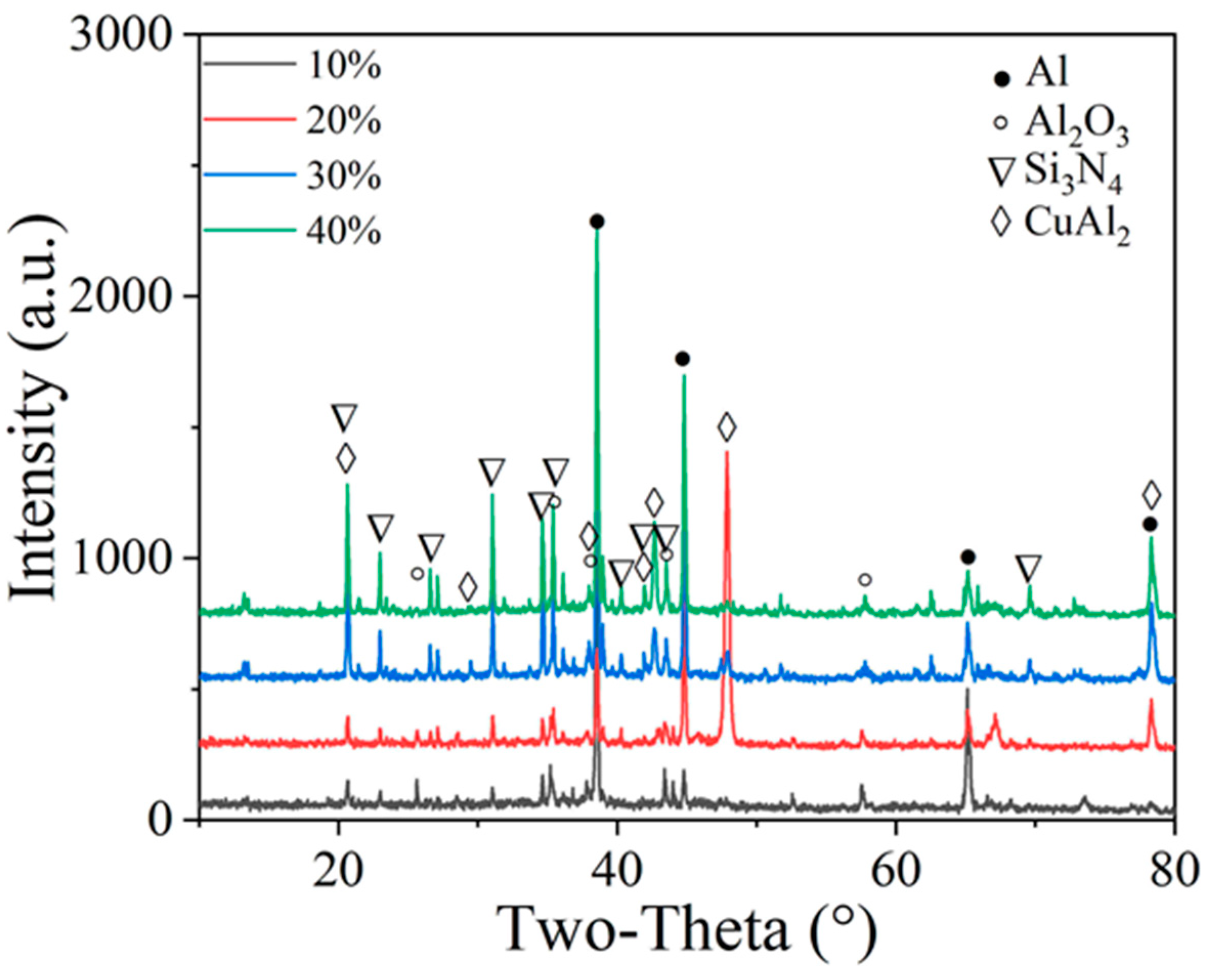
Figure 4.
Surface morphology of the S1–S4 wafers after polishing.

Figure 5.
Porosity of the S1–S4 wafers.
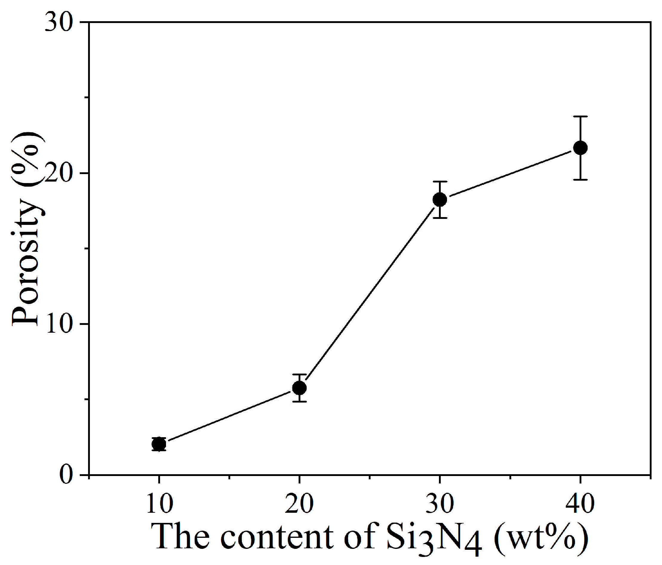
Figure 6.
Microhardness of the S1–S4 wafers.

Figure 7.
Tribological curves of S1–S4 wafers in water.
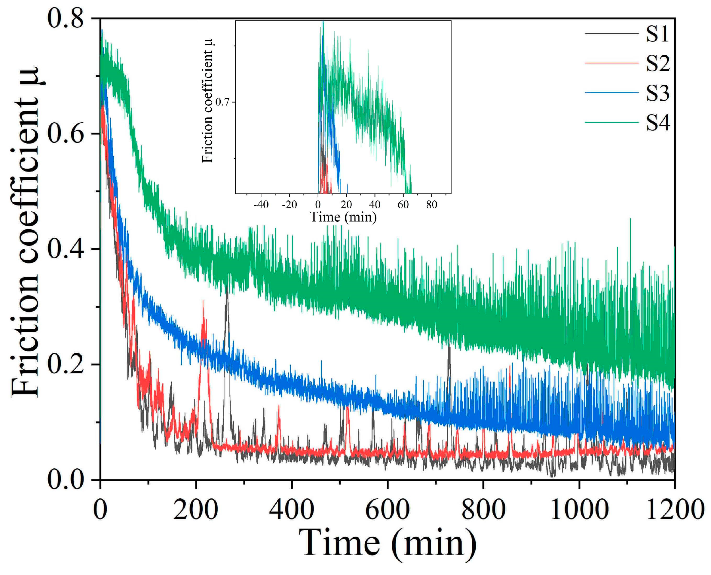
Figure 8.
Wear morphology of Si3N4 ball and the wafers.
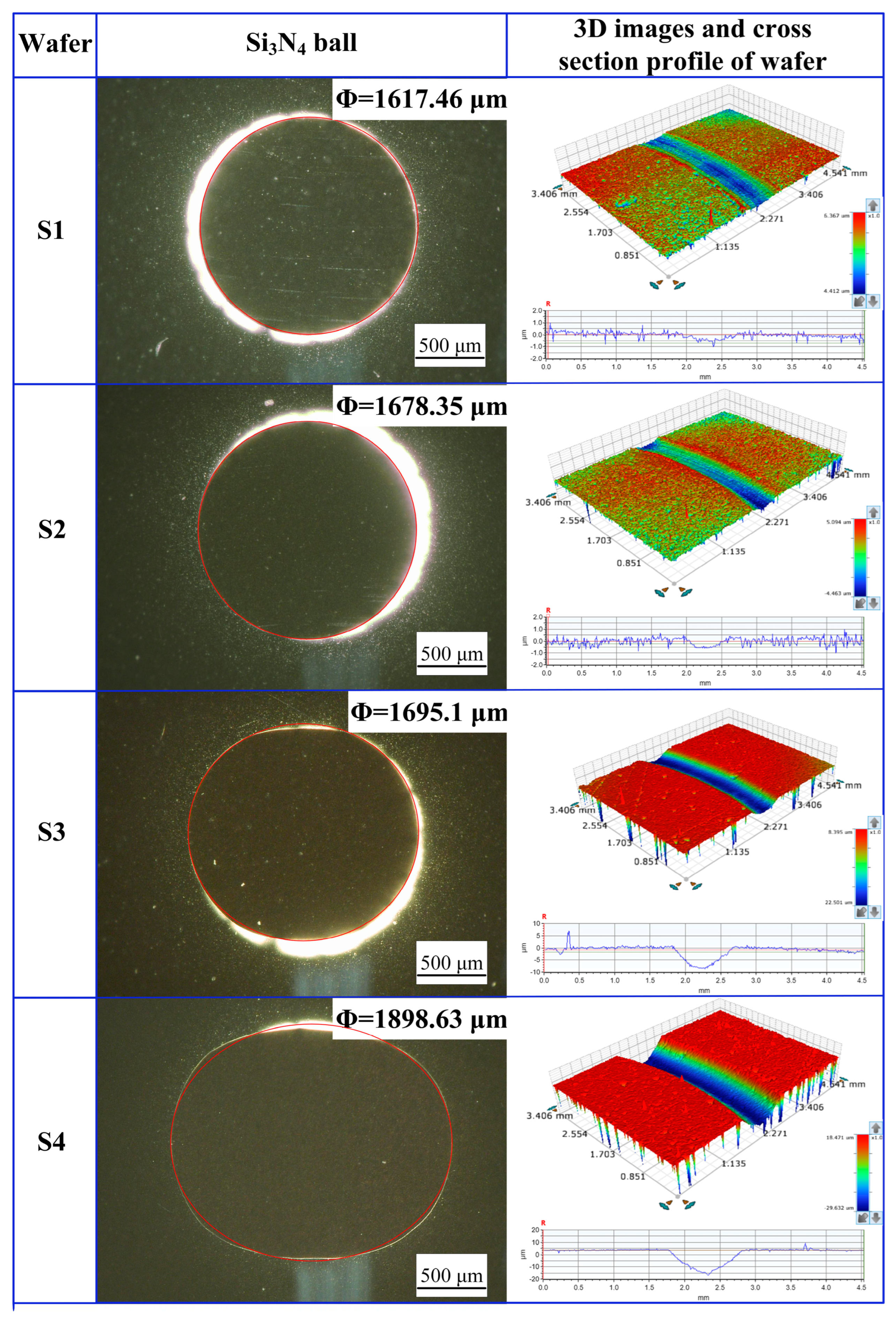
Figure 9.
Wear volume of the S1–S4 wafers and Si3N4 ball after 1200 min friction test.

Figure 10.
The images and 3D wear morphologies of the S2 wafers and Si3N4 ball at different time sliding stages (a) 50 min, (b) 100 min, (c) 200 min, (d) 400 min.
Figure 10.
The images and 3D wear morphologies of the S2 wafers and Si3N4 ball at different time sliding stages (a) 50 min, (b) 100 min, (c) 200 min, (d) 400 min.
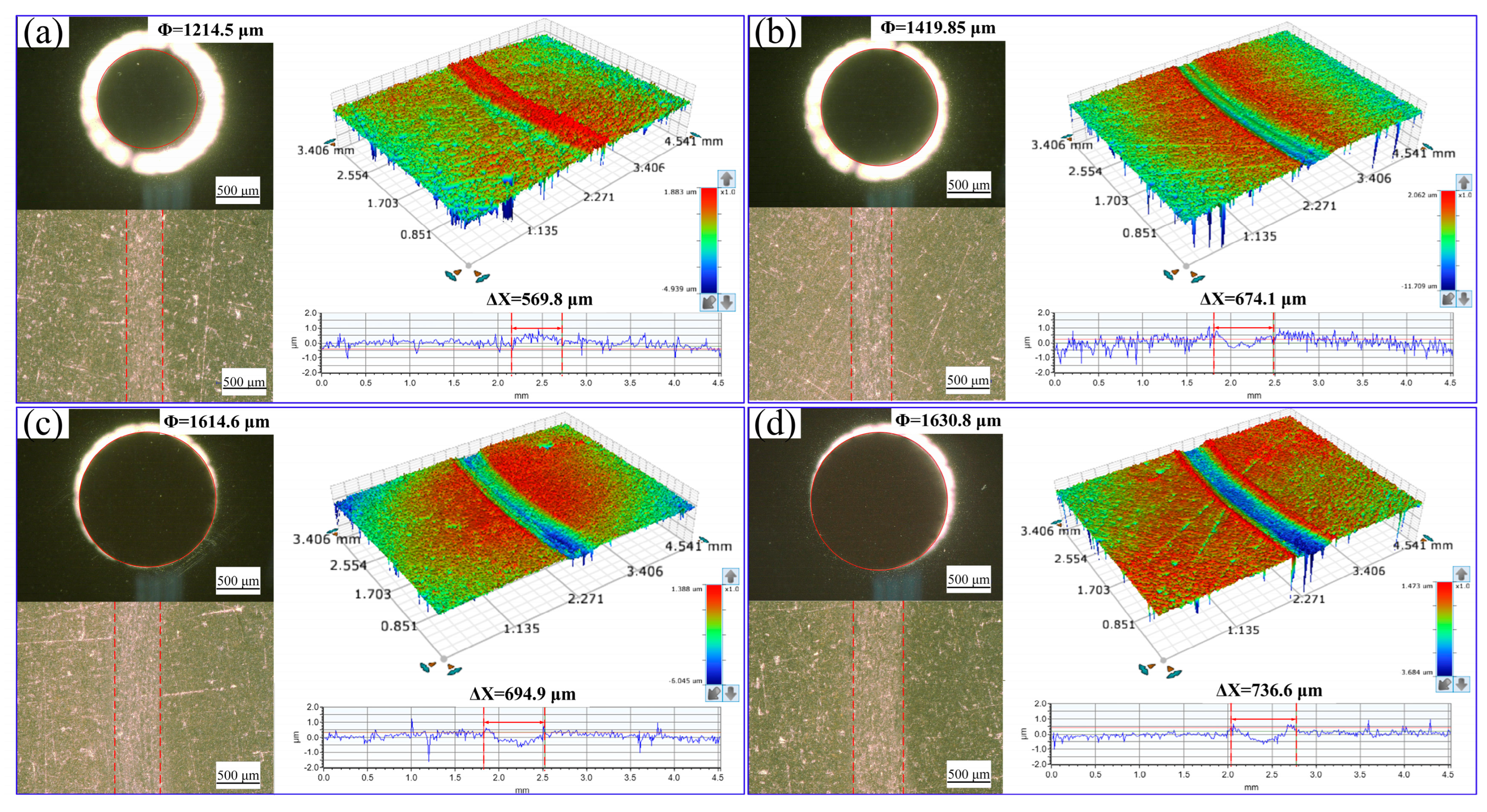
Figure 11.
SEM images (a,b) of the worn S2 wafer surface and EDS analysis (c) according to the area A shown in SEM image (b) after 50 min.
Figure 11.
SEM images (a,b) of the worn S2 wafer surface and EDS analysis (c) according to the area A shown in SEM image (b) after 50 min.
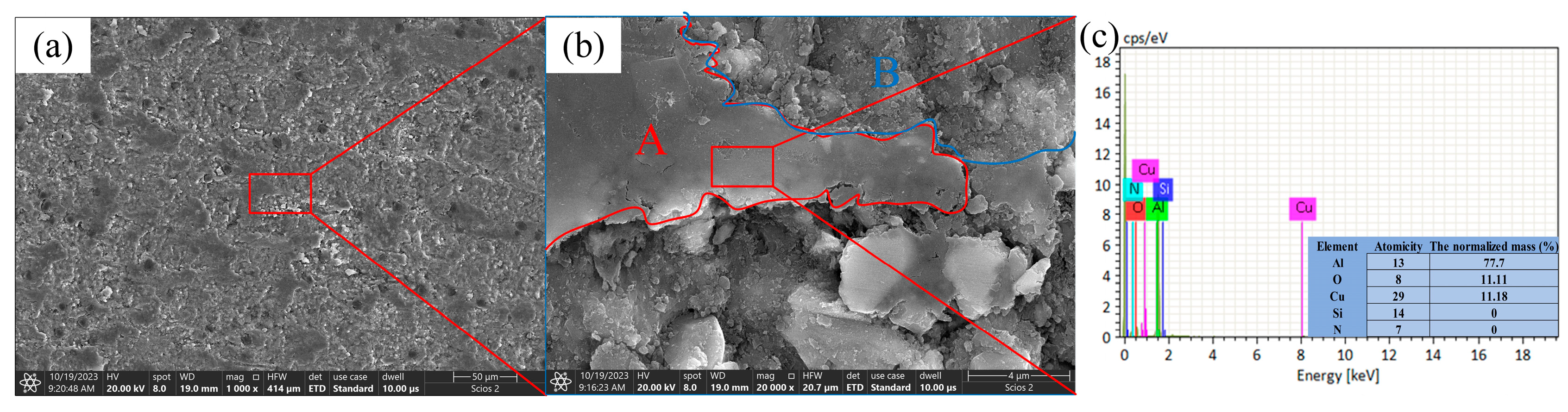
Figure 12.
The wear volume of the S2 wafers and Si3N4 ball in different time periods.
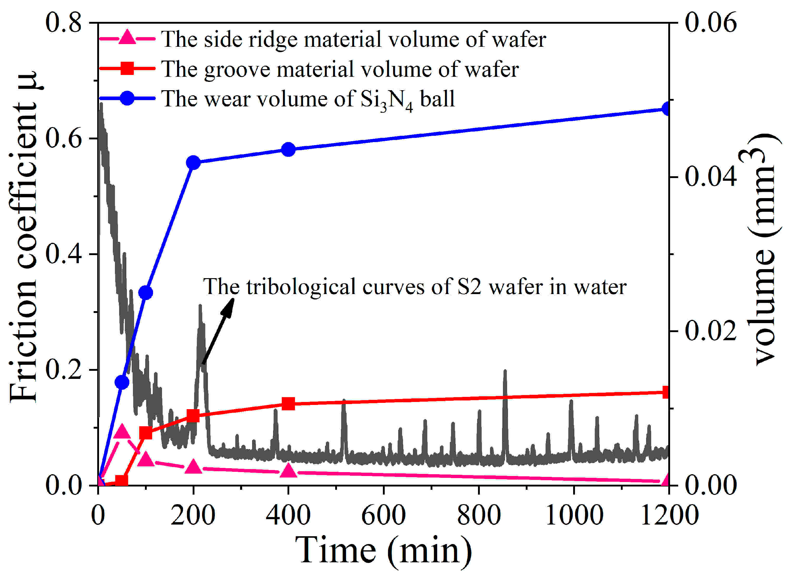
Figure 13.
Contact pressure between the wafer and the Si3N4 ball and conductivity of aqueous solution at different time periods.
Figure 13.
Contact pressure between the wafer and the Si3N4 ball and conductivity of aqueous solution at different time periods.

Table 1.
Chemical plating activation and sensitization formula.
| Sensitization | Activation | |||
|---|---|---|---|---|
| Reagent | SnCl2·2H2O | HCl | PdCl2 | HCl |
| Concentration | 16 g/L | 50 mL/L | 0.25 g/L | 10 mL/L |
| Condition | Constantly stirred for 30 min, cleaned 3 times in deionized water | Constantly stirred for 20 min | ||
Table 2.
Composition of bath and reaction conditions for electroless deposition.
| Reagent | Concentration | Condition |
|---|---|---|
| NiSO4·6H2O | 25 g/L | pH = 5.5 Temperature: 85 °C Time: 2 h |
| NaH2PO2·H2O | 18 g/L | |
| CH3COOH | 20 mL/L | |
| CH3COONa | 15 g/L | |
| Thiourea | 0.25 mg/L | |
| NH3·H2O | / |
Table 3.
The component and name of the Ni-coated Si3N4 reinforced Al-Cu alloy matrix composites wafers.
Table 3.
The component and name of the Ni-coated Si3N4 reinforced Al-Cu alloy matrix composites wafers.
| Wafer Sample | S1 | S2 | S3 | S4 |
|---|---|---|---|---|
| Ni-coated Si3N4 mass percent (wt%) | 10 | 20 | 30 | 40 |
Disclaimer/Publisher’s Note: The statements, opinions and data contained in all publications are solely those of the individual author(s) and contributor(s) and not of MDPI and/or the editor(s). MDPI and/or the editor(s) disclaim responsibility for any injury to people or property resulting from any ideas, methods, instructions or products referred to in the content. |
© 2024 by the authors. Licensee MDPI, Basel, Switzerland. This article is an open access article distributed under the terms and conditions of the Creative Commons Attribution (CC BY) license (https://creativecommons.org/licenses/by/4.0/).
Share and Cite
MDPI and ACS Style
Peng, Y.; Dai, Q.; Huang, W.; Wang, X. Water Lubrication of Al-Cu Composites Reinforced by Nickel-Coated Si3N4 Particles. Coatings 2024, 14, 225. https://doi.org/10.3390/coatings14020225
AMA Style
Peng Y, Dai Q, Huang W, Wang X. Water Lubrication of Al-Cu Composites Reinforced by Nickel-Coated Si3N4 Particles. Coatings. 2024; 14(2):225. https://doi.org/10.3390/coatings14020225
Chicago/Turabian StylePeng, Yanan, Qinqwen Dai, Wei Huang, and Xiaolei Wang. 2024. "Water Lubrication of Al-Cu Composites Reinforced by Nickel-Coated Si3N4 Particles" Coatings 14, no. 2: 225. https://doi.org/10.3390/coatings14020225
Note that from the first issue of 2016, this journal uses article numbers instead of page numbers. See further details here.