


A Guiding Framework for Process Parameter Optimisation of Thermal Spraying
by
 , , and
Viswanathan Venkatachalapathy
1,
Nirmal Kumar Katiyar
1 ,
,
Allan Matthews
2,
Jose Luis Endrino
3 and
Saurav Goel
1,4,*
1
School of Engineering, London South Bank University, London SE1 0AA, UK
2
Department of Materials, The University of Manchester, Manchester M13 9PL, UK
3
Department of Engineering, Universidad Loyola Andalucia, Avenida de las Universidades s/n, 41704 Dos Hermanas, Spain
4
Department of Mechanical Engineering, University of Petroleum and Energy Studies, Dehradun 248007, India
*
Author to whom correspondence should be addressed.
Coatings 2023, 13(4), 713; https://doi.org/10.3390/coatings13040713
Submission received: 21 February 2023
/
Revised: 27 March 2023
/
Accepted: 28 March 2023
/
Published: 31 March 2023
(This article belongs to the Topic Multi-Process and Interdisciplinary Approaches in Modern Coating and Surface Design)
Abstract
:Currently, most thermal spray coating service providers expect original equipment manufacturers (OEMs) to suggest the coating recipe, comprising of the right coating equipment, starting process parameters, type of inert gases, and robot program. The microstructure and mechanical properties may not comply in the first few runs. Feedback from a competent material testing service provider forms the initial step to adjust the parameters in the development journey, toward identifying the processing parameters required to obtain an acceptable coating. With the surge of interest in sustainable manufacturing, the time spent on trials in the future will shrink, and a more rigorous process needs to be applied to achieve the “right-first-time manufacturing” approach in thermal spraying. However, a framework for the systematic development of thermal spray parameter optimisation is lacking. This article provides a framework, based on a logical acumen, in selecting the right process parameters, using available data and prior knowledge about the thermal spraying process. To that end, the article summarises the extant developmental journey of thermal spray process parameters, by covering the aspects of equipment choice, robot and spray parameters, and how to minimise iterations, using diagnostic tools to get to the end solution most efficiently. This article, in its current form, will serve as a good guide for early career engineers and scientists or workers, to minimise the time processing window, by avoiding endless iterations to deposit a certain type of coating using thermal spraying. Besides, this work is also aimed at transforming academic research innovations to a robust and repeatable industrial manufacturing process.
1. Introduction
Thermal spray industries provide services to a variety of sectors, such as aviation, power generation, and medical implants [1,2]. Many enterprises develop their coating recipe in-house, to protect proprietary information. The spray parameters used during coating deposition such as gas flow rate, type of gas, substrate choices, surface preparation, and feed rate can jointly influence the final results, and this is why the development of coating parameters, to achieve the desired coating quality, can sometimes take a few months [3]. With the incorporation of data-driven modelling, [4,5,6] it is expected that the lead time associated with this development work can accelerate, however, a physics-based rationale [7] can aid in the selection of the right parameters for the shop floor engineers, without having to perform intensive simulations using data exercises.
There could be multiple pathways to deposit a certain coating, but to be cost and time efficient, the response time in developing an optimal recipe is the most important determining factor. The success of developing coatings to comply with the desired specifications, depends on many factors, such as the forecast of the volume of parts to be coated annually, post-coating finish requirements, and the base material type and its melting point. The tendency of the coating material to oxidise, its melting point, the density of the powder, and the surface roughness of the coating need to be factored in when developing the process parameters [8]. Additionally, the base material’s physical properties, microstructural features, mechanical properties of the coating, and its end applications, also need to be factored in, prior to the process development. The selection of equipment such as coating gun, coating process controller, powder feeder is an equally important consideration, as it has implications for the equipment operation and its maintenance. This also includes the choice of wheel feeders and fluidised bed feeders, as this could become an upfront cost in governing or influencing the feeder maintenance. Wheel feeders come with fewer digital parts and thus could be extremely useful in coping with shutdowns related to electronics, as in the case of fluidised bed feeders. However, the downside could be measuring the live feed rate, although OEMs have started to provide load cells in the wheel feeders [9].
Currently, the OEM-provided parameters serve as a good starting point in the parameter optimisation journey. There is no article in the literature that provides a physics-based rationale as to how can someone reduce the iterations of the coating recipe optimisation. In pursuit of this question, this work outlines a procedural approach one can take, as guidance toward developing a rationale for optimal parameter selection.
Several factors can influence the matrix of cost vs. performance, and in the digital age of “responsive manufacturing”, where demand–supply gaps grow within a fraction of days, it is desirable to expedite the coating process development. Taking this as the main motivation, this article provides a framework to account for various factors, challenges, and nuances of process parameter development, while providing a ready guide to field practitioners to speed up the development of new coating. The article does not focus on a single thermal spray process but on general air plasma, HVOF (High Velocity Oxygen Fuel), wire arc, and flame spray processes.
2. Process and Equipment Selection Based on Materials
2.1. Materials
It is important to know the materials that need to be coated before attempting the process parameter development. The flow chart shown in Figure 1 can guide the decision-making process for selection of the type of spraying process. Figure 1 is not comprehensive by any means, but it provides a good guide to develop a technical rationale for the selection of the right spraying method, linking materials with the manufacturing process. This flow chart is designed to choose a process based on the coating’s physical properties, such as melting point and morphology. However, other factors such as masking of overspray locations and post-coat surface finish, may also be considered to expand this flowchart. Parameter development needs unbiased thinking, as there could always be a better choice of process and material when it comes to meeting the end properties compared to how others may have obtained it. Environmental sustainability should constitute the primary factor in asserting the final choice, to achieve a “net zero” focus in thermal spraying.
2.2. Inert Gases vs. Combustibles—An Educated Choice
Inert gases such as nitrogen, argon and helium [15] are cleaner choices for plasma spraying. There are also other choices such as hydrogen, oxygen, acetylene, propylene, and propane, which are used in processes such as HVOF and flame spray. The discussions held during the Thermal Spray Week [16], which was an event organised by the EPSRC Digitalised Surface Manufacturing NetworkPlus, from 21–25 March 2022, revealed that many developed countries plan for liquid tanks of these gases, except for hydrogen, as a sustainable long-term measure to avoid any shortages of raw material. As for developing countries, liquid tanks are a premium to pay, and inert gases are much less affordable compared to hydrocarbons. A schematic of recommended gases for each process and material is shown in Figure 2.
The consideration of gases for heat generation during plasma spraying requires a good understanding of the physics of dissociation and ionization of the gaseous atoms of the atmospheric pressure jet plasma. Currently, four gases are popularly used in the plasma spraying process. Two of them are monoatomic gases (helium and argon) and two of them are diatomic (hydrogen and nitrogen). Hydrogen gas has one electron in its shell. Extreme energy is required to dissociate a diatomic molecule into monoatomic. Once dissociated, the heat energy produced knocks out the electron from the monoatomic shell, thereby causing the hydrogen to become a cation, and the free electron further aids in the ionisation process. Likewise, nitrogen has five electrons in its outermost shell and the diatomic gas is first dissociated into the monoatomic variant. This is followed by the liberation of electrons and the formation of nitrogen cations. Thus, hydrogen and nitrogen plasmas carry most heat, which is necessary to melt ceramics and triballoys. It must be noted that air plasma spray tends to oxidise metallic and alloy particles, especially with nitrogen and hydrogen gases. Thus, either argon or helium is preferred, although they are quite expensive. Argon and helium are inert gases, and their outer most shell is filled with the maximum capacity of electrons, and it requires a lot of energy to liberate an electron from the outermost shell. However, once liberated, the plasma energy is sufficient to melt materials such as metals and alloys and, due to their inert nature, the coating has fewer oxides. Figure 3 highlights the enthalpy of various gases, which can form a good basis to understand the energy needs associated with the spraying of material, in selecting the right gas.
2.3. Choices within an Air Plasma Spray Process
For the plasma spray process, several types of spraying guns, ranging from 20 to 200 kW power are available in the market. This often leads to confusion as to which type of gun is most appropriate. The first choice on this front begins by understanding the portfolio of the coating process, especially considering whether there are any future expansion plans. For example, a 60–80 kW gun would be sufficient to coat porous coatings such as the thermal barrier coating (TBC) [20], Triballoys [21], and Al–Si polyester [22]. However, if there is a plan to venture into segmented TBC [23], a natural choice would be to set up a 200 kW power supply in the first place. This high-capacity power supply should be able to coat porous, as well as denser segmented coatings. A higher-power gun requires installation of a higher-capacity electrical transformer, so there would be differences in the capital expenses on electrical installation depending on the gun power. It is prudent to have a heat exchanger and a closed loop chiller that can cater to most spray guns. Typically, guns in the range of 60–100 kW would need a water flow rate of 35–45 L per minute, to extract heat and prolong hardware life, and the high energy guns that could coat the segmented coating would need a water flow rate of 55–60 L per minute.
2.4. Robots for Coating Development
The choice of a robot, and its ability to withstand a certain payload (to hold the plasma discharge from a gun carrying gases and powder), is crucial. The choice of the gun decides the payload, which in turn depends on the part geometry and the location of the coating (internal diameter (ID) vs. outer diameter (OD)). The potential of the robot must be fully utilised and not just confined to 6-axis or 8-axis movements. Many accessories such as air jets, auxiliary cooling, gun start/stop, and powder start/stop could be triggered by the robot and can be coded along with the robot program to automate and improve the quality of coatings as much as possible.
Robots can play a vital role, especially if the coating controllers are analogue and not much budget is available to upgrade them to a PLC based controller (for example using a 9MC controller vs. a UniCoat or MultiCoat).
Future robotics should disrupt the conventional coating controller technologies by way of metering and controlling the gas flows and pressure, and powder feeder choice, so that critical real estate on the shop floor is spent on processing more parts. An ideal robot controller should control the mass flow controllers, powder feeder, gun, power supply, and the robot mechanical unit, rather than just controlling the robot mechanical unit. Speed and robot spray distance are important parameters to address the coating quality and manufacturing issues. These two parameters are generally disregarded by the engineers and more focus is given to gun parameters instead. In the true sense, from achieving porous/dense microstructures to achieving optimum tensile strength, a suitable robot can create the appropriate quality of coatings. With low kW energy output guns, it is possible to achieve dense microstructures and high-tensile-strength coatings just by robot programming parameters such as standoff distance and robot speed. Offline robot programming is useful to achieve complex geometry coverage and to achieve better coverage on curved surfaces, such as radius and off-angle locations. Robots are capable to switch guns, or measure coating thickness (such as an eddy current thickness meter) mounted to it. It is good to have a robot speed of 500 mm/s to understand the deposition rate (microns/pass). Plasma spray parameter development can start with a spray distance of 100 mm, flame spray and HVOF can have a minimum of 200 mm to start the development process, whereas a cold spray process can typically start with a spray distance of about 25–50 mm.
2.5. Physical Properties and Parameter Correlations
It is important to know the physical properties of the powder before selecting the carrier gas, type of gun, equipment, and process type. Physical properties such as melting point, apparent density, particle size, morphology, and chemical composition can play an important role in defining the thermal spray parameters. It is important to know why ceramics are not coated with HVOF [24] or why plasma spray is seldom used for spraying aluminium or zinc [25]. Figure 4 shows the elements marked on the periodic table that are typically sprayed with certain processes. Plasma spray can melt high-melting-point materials such as zirconium oxide and WC, which makes this process preferable to deposit these hard coatings. On the other hand, HVOF may be used for improving the density of coating chemistries such as WC and improving the as-sprayed surface finish [26].
A high hydrogen flow creates enough enthalpy to enable complete melting and avoid unmelts in the process. Low density metals and alloys, such as aluminium and titanium powders, require more carrier gas, to be pushed into the flame against the turbulent plasma plume and to melt, contrary to the high-density materials such as WC or Mo. It is important to know the difference between apparent density and tap density, for planning powder feeder capacity for uninterrupted production runs. A spherical powder is easy to flow through the powder hose compared to other morphologies. Especially for nano-powder, it is important to dry the powders to get a spherical morphology before the spray is commenced [27]. Materials which tend to oxidize are better to be sprayed with inert carrier gases, such as argon or helium, rather than hydrogen. Oxidation renders the coating harder and may thus exceed the specified upper limit, and sometimes render the coating brittle. The mismatch in the coefficient of thermal expansion is another prime factor to consider while choosing plasma spray. For example, using plasma spray to deposit Ni–Cr powder on an aluminium substrate [28], would prove ineffective because of the enthalpy generated by the plasma gases, which is too high for the aluminium substrate. Thus, the wire arc process is a suitable choice, to keep the substrate temperature low and deposit strong coatings over aluminium. Axial injectors are designed to inject the powder at 90° to the axis of the plume, while radial injectors are designed to be in line with the same axis of the plume. The selection between an axial or a radial injector [29], requires a deeper understanding about gun design and the material’s physical properties. It is prudent at this stage to understand the relationship between material choice (Figure 1), choice of gases (Figure 2), physics of enthalpy generation (Figure 3), and the periodic table (Figure 4), to have a holistic expectation of the end results to be achieved with the parameter choice.
2.6. Spraying Low Melting Point Materials Such as Aluminium
Aluminium and magnesium are low-melting-point base materials, and thus there is a large coefficient of thermal expansion (CTE) mismatch between the coating and the base material. Care must be taken to grit blast the surface to a higher roughness, to ensure adequate adhesion. The temperature of the coating during pre-heating and during coating must not exceed a threshold temperature. Use of wire arc coatings is very useful for coating aluminium base materials, especially due to wire arc being an economical low-temperature coating process.
2.7. Process Parameter Development
After the selection of a suitable power supply and thermal spray gun, one must pay attention to the right selection of the nozzle, electrode, gas, robot speed, spray distance, powder feed rate, carrier gas flow, and the hopper pressure. The selection of these parameters requires extensive spray iterations and repeatability checks, backed up with robust material testing feedback.
The use of design of experiments (DOE), involving methods such as Taguchi design, can aid to significantly reduce unnecessary iterations. Additionally, particle diagnostic tools, such as particle velocity monitoring and substrate temperature monitoring, could help to screen the iterations, to start with a reasonable DOE [30,31].
Development of parameters starts with a DOE, followed by a good statistical analysis, with tools such as analysis of variance (ANOVA) or, for instance, random forest regression (RFR) [32]. An example case is shown in Table 1, to highlight a case study where 8YSZ powder is to be sprayed with a 9MB gun, and it is important to note that hydrogen and standoff distance were determined to be the important parameters to change, leaving all other parameters unchanged. Four different sets of parameters were applied in spraying 9MB and 8YSZ powder on super alloys, and the relevant output data providing information about the microstructure and tensile properties are shown in Table 1.
After obtaining the experimental outcomes, a statistical software, such as Minitab, can be used to obtain a matrix plot of the data, to compare the two most important parameters (i.e., flow rate of hydrogen and spray distance) affecting the quality of coating, namely, kW and the thickness/pass. It can therefore be concluded, based on the matrix plot shown in Figure 5a, that hydrogen and standoff distance are the most influential parameters in changing the quality of the coating, and the subsequent array tested only the interaction between these two variables, as shown in Figure 5b.
Based on the DOE in this case, it is easy to decide the standoff distance should be 100 mm with five standard litres per minute (SLPM) hydrogen. The next steps involve repeatability checks and analysing whether all the desirable properties, such as porosity and tensile strength, meet the target specifications. As shown in Figure 6, a histogram plot showing properties such as porosity, unmelts, thickness/pass, and tensile strength could help to identify if the process is within the compliance window. It is important to publish a range instead of a specific number, for users to achieve the target specifications without any difficulties. Hence, it is important to obtain the mean, median, and standard deviation from such repetitive studies (see Table 2).
For achieving high tensile adhesion for materials with high oxygen affinity, HVOF could be an alternative, to achieve tensile strength with minimal oxidation. Although predominantly plasma spray is used to melt ceramic powders, HVOF could be used for some fine ceramic particle sizes, ranging from 10–20 microns [23]. Plasma-sprayed coatings [37] generally achieve a higher tensile strength compared to flame sprayed [11]. The selection of the nozzle bore size in the plasma gun is dependent on the amount of powder which needs to be deposited through the gun. Typically, 35–50 g/min of powder would need a smaller bore size nozzle (6 mm) and powder feed rates of 100 g/min would need a bore size of twice the diameter (12 mm), to get better deposition efficiency.
In general, nitrogen (primary) and hydrogen (secondary) are good choices for plasma guns to melt alloys with high melting points, while argon (primary) and hydrogen (secondary) can also be used, but are an expensive choice. For processes involving nitrogen as the primary gas, it is good to have an argon start first, to ensure that the nozzle hardware (typically copper) does not melt during the arc discharge. Initially, the coating development can start with coating trials made on a flat plate, and this can be moved to a round part if the coating is on a round part. Table 3 summarizes the effects of different parameters on the coating properties.
2.8. Plume Study
A well-defined plume should have no fluctuation in the plasma jet. This can be studied with thermal imaging cameras, as a low-cost monitoring tool. Excessive fluctuation in the plasma plume would indicate the necessity to check for physical damage in the hardware and may also require reassembly of the gun. If the arc is attached to different locations of the nozzle, then it could be due to nozzle damage. It is then worth performing a plume plate study. A plume plate study is a process where a gun is moved in front of a flat plate and focused on a point for 5–10 s, to study the spot size and find out gun whether there are any hardware/powder injector issues. Before performing a plume study, it is worth knowing the expectation of the plume slice at a particular standoff distance. If a plume is sliced in the transverse direction of the powder impinging direction, then one could find out the particle density in the core vs. periphery, spot size, particle temperature, and velocity. Figure 7 provides an overview of the plume cross-section. Future lens technology should be able to estimate the ingredients of the plume cross-section while monitoring the plume axially.
Figure 8 reveals the spot location concerning the target crosshair on the flat plate. If the spots shoot exactly at the target, both the robot tool centre point (utool in the Fanuc robot terminology), or the tool centre point (TCPF in ABB robot terminology), it means that the nozzle/injector is in a good condition. Sometimes, even with new hardware/injector replacement, there is a possibility of the spot size being off target. The reason could be a damaged gun mount or an inaccurate tool centre point. It is good to involve a robot programmer at that stage, to modify the tool centre point coordinates, to bring back the spot to the target. The ovality of the particle plume can be caused either by a worn-out injector or by the carrier gas pulsing and must be corrected appropriately.
The appropriate primary and secondary gas flow rates used for plasma generation and gas pressure, depend on the melting point and composition of the powders. In general, a high flow is needed to melt high-melting-point alloys. A high flow gas rate also helps to achieve superior hardness and tensile strength, but care must be taken not to increase the oxide content in the coating. Segmented coatings need higher energy and the part sometimes needs to be insulated or externally heated, to maintain the part temperature.
3. Plume Monitoring and Process Diagnostics
3.1. Is the Plume Coaxial to the Nozzle Axis?
To increase the residence time of the particle in the plume, a 75° injector (Figure 9) can be used to push the particle stream up against the plasma, thereby getting the most out of the intense plasma plume.
Having the optimum amount of carrier gas to push the powder in the plasma or combustion flame, is critical in ensuring that a higher proportion of particles are melted and unmolten particles in the coating formation can be avoided. This is regardless of whether high-plasma-generating gases, such as nitrogen, are be used. Using welder’s glasses to view the plume before coating is of paramount importance, to ensure that the powder plume is coaxial to the nozzle.
Figure 10 shows that dense bond coats can be better achieved with the HVOF process, especially by using hydrogen; it is easier to achieve porous coatings by using a 50–100 kW gun, and segmented coatings by using a 200 kW gun. It is also possible to obtain dense, segmented coatings with low kW guns, but it takes time and a lot of powder gets wasted in performing the trials. It is wise to select a gun that is short, able to coat outside parts, and easy to handle for the operator. It is also appropriate to use a long ID gun to coat internal diameter parts.
Depending on the location to be coated, it is wise to choose a table that is shorter than the robot arm by half, so that it is in easy reach for the robot arm. It is better to have a table with at least 100 RPM and 300 kg payload for handling gas turbine and aviation parts. However, parts such as the rotor of a gas turbine, need a dedicated lathe or a turn table of at least 10-tonne capacity to handle the load and a minimum of 25 RPM.
3.2. Nozzle Design and Health Check of Hardware
The choice of nozzle plays an important role in developing coating parameters. It can be quite confusing to think about what nozzle to start with. The selection is constrained by the gun itself. Several nozzles can be chosen for the same gun. For example, the Metco 3MB gun, can accommodate G, GP, GH, and GE nozzles. These nozzles have different exit diameters, and the converging divergent designs are suited for high-velocity, high-temperature particle choices. For example, a GP nozzle is suitable for spraying WC–Co at a high velocity with Ar/H2 gas, while a G nozzle is good for low-velocity/high-temperature particle states, for a ceramic coating such as YSZ.
The anode serves the dual role of electron receptor and shaping the plasma jet, and is thus a critical component in determining the gun’s transfer of energy to the particles. The terms nozzle and anode can be used interchangeably here. Different nozzle designs exist to achieve different gas velocities, or to suit plasma gases or coating deposition rates. The anodes are designed to be easily cooled by internal water flow, so design components such as water/gas seals and cooling fins generally protect a nozzle’s exterior. Heat is transferred to the anode by condensation of electrons; electron enthalpy flow and thermo-diffusion effects; heavy particle and electron conduction; and ion recombination at the anode surface [7].
Electrons exiting the cathode ionically, excite the gas in the convergent zone. Thus, the generated plasma is constricted to the central axis of the anode and the cathode. Therefore, apart from where the plasma bridges the anode and the cathode, the plasma should be centrally aligned when it emerges from the nozzle. Some nozzles have a perfectly flat exit (GP nozzle of Metco) to the face of the gun, while some nozzles have a divergent portion (GH nozzle of Metco), which enhances the diameter of the plume and thereby gives more enthalpy and less velocity to the particles. In the case of the GP nozzle, it would be prudent to use low-melting and low-density alloys compared to the GH nozzle, which is better for high-melting-point and dense powders. Arc attachment should be constrained to a specific location and should not be allowed to extend and retract. This will lead to voltage fluctuation and thereby lead to improper melting and a poor microstructure.
Nozzles (anode) often get eroded or partially melted when nitrogen gas is used during the gun start in the case of plasma spray, and the gun barrel, in the case of HVOF, gets choked due to powder build up. The electrode (cathode), although made of tungsten, or thoriated or lanthanated tungsten, tends to erode if the arc becomes constricted because of premature melting of nozzle. Thus, the use of argon gas to start the gun, in the case of plasma, and providing water cooling as mentioned in the manual, with deionised water, and checking the conductivity of the water at regular intervals, will maintain the integrity of the gun and produce consistent coating with the parameters developed.
3.3. Use of Diagnostic Tools for Reducing Iterations
The use of particle state monitoring [42] at the desired standoff distance, can reduce the number of iterations of sampling and sectioning to see the microstructure and testing for mechanical properties. It is important to monitor the particle temperature, velocity, and the intensity of the plume, and determine their relevance to the microstructure obtained. If the particle temperature is low, we can expect unmelts in the microstructure, or if the velocity is low, we can expect more porosity. Thus, the particle states and microstructure obtained from few iterations can be processed using the Python language, to estimate the expected temperature and velocity states for a desired target microstructure. Use of IR equipment [43] to monitor the surface temperature of the base material, can help to tweak the robot parameters, and auxiliary cooling needs to target desirable mechanical properties. A digital library of particle states vs. microstructural properties could be created for future review and improvement of the processes.
Likewise, acoustic emission (AE) has been used for decades, in industries such as aerospace and automotive, for quality control purposes. Its potential applications are far-reaching, and include predictive maintenance and health monitoring during coating deposition. In general, AE techniques are characterised by the emission of sound waves, which can be detected and monitored using specialised equipment, such as an acoustic transducer and a set of amplifiers. In one study, multi-linear regression analysis has been used to correlate the number of AE events during a four-point bending test of YSZ topcoat and NiCrAlY, to the spray parameters [44]. The analysis revealed that coatings with thicker bond coat sprayed on a heated substrate at shorter distances, released higher AE energy under bending. As expected, the greater emission activity and higher AE energy were evidence of severe cracking. Acoustic emission has also been applied in situ, during HVOF processes, monitoring the signals at the substrate [45]. In this case, the sources of acoustic emission included particle impact, released strain energy, thermal mismatch, cracks in the layers, and noise in the coating chamber. Another similar study looked into airborne aeroacoustics (AAE), by positioning a piezoelectric sensor near the torch [46], the data obtained proved that the AE contains measurable information related to the spraying parameters, such as the powder feed rate, the spraying distance, and the resulting micro-hardness of the coating. Both of these acoustic monitoring techniques have been implemented industrially, to detect and identify defects in materials or components before they become visible or cause failure, with the aid of machine learning algorithms [47].
4. Other Important Considerations
Masking parts for sprayed coatings is perceived as an art. There are three primary types of masking: (i) tape masking, (ii) silicone paste masking, and (iii) metal masking. For the HVOF process, liquid fuel guns have more powder throughput compared to gas-fuelled guns, and the choice of maskants must be accurate. When the HVOF process is chosen, it is to be ensured that the part design is amenable to receive metal masking, since other types of masks such as tape masking will not withstand the HVOF gas pressure and flow, and the tapes will tear during coating. Silicone paste masking is useful for locations such as cooling holes. Tape masking is useful to cover overspray on parts coated with plasma spray and wire arc and flame spray guns. With careful masking, the amount of blending needed to clean the over-sprayed surface can be reduced. In addition, the coated surface roughness can be reduced or increased by careful choice of the coating powder size, spray distance, and gun. This may eliminate the need for post-coating polishing or machining to achieve roughness.
The aspects discussed in Section 2 and Section 3 were valid primarily for the plasma spray, HVOF, and flame spray processes and hence can be used as a framework to develop a recipe for parameter development. Cold spray, by virtue of being a kinetic energy driven process, is not discussed extensively in this article, but a similar type of rationale can be drawn for this variant of spraying.
5. Conclusions
Thermal spray is an excellent overlay coating technique, used in a myriad of engineering applications. Careful choice of equipment, process, and parameters will eliminate expensive masking, prevent material waste, and produce long-lasting superior coatings, that can help to achieve the ambition of the thermal spray community, to achieve “net zero”. However, significant barriers exist in this direction, of which a particularly important one is the need to reduce or eliminate the number of iterations involved in developing process parameters or the recipe for the development of a new coating–substrate combination. In this article, we present a scientific rationale to help allow the thermal spray community to achieve the right-first-time manufacture approach, by having an appropriate understanding of the role that each important variable in the thermal spray process plays and how it affects the outcome. It is shown that, parameter development involves an interdisciplinary approach, from materials engineering, mechanical engineering, and robotics, as well as the programming of tool paths. The developer of these process parameters must vet the properties that can be achieved, by repeating the development of the parameters before declaring the specifications. It then becomes easier for the thermal spray manufacturing professional to take the parameters forward in the manufacturing unit and produce consistent quality parts. The purpose of this work is to emphasize the subtle details that one needs to pay attention to while developing these parameters.
Author Contributions
Writing–original draft, Methodology and conceptualization: V.V.; Reviewing and editing: N.K.K.; Mentoring, resources and supervision: S.G.; Project Administration: J.L.E. and A.M. All authors have read and agreed to the published version of the manuscript.
Funding
All authors would greatly like to acknowledge the financial support provided by the UKRI, via grant nos. EP/S036180/1 and EP/T024607/1, feasibility study awards to LSBU from the UKRI National Interdisciplinary Circular Economy Hub (EP/V029746/1), Transforming the Foundation Industries: a Network+ (EP/V026402/1) and the Newton Fellowship award from the Royal Society (NIF\R1\191571). J.L.E. gratefully acknowledge funding from Spanish Ministry of Science (Projects PID2021-128727OB-I00 and TED2021-132752B-I00).
Institutional Review Board Statement
Not applicable.
Informed Consent Statement
Not applicable as this study didn’t involve human beings.
Data Availability Statement
There is no supporting data needed to publish this article.
Acknowledgments
We sincerely acknowledge the generous help of Senior management to help setup the Thermal spray facility at LSBU.
Conflicts of Interest
The authors declare no conflict of interest.
References
- Herman, H.; Sampath, S.; McCune, R. Thermal Spray: Current Status and Future Trends. MRS Bull. 2000, 25, 17–25. [Google Scholar] [CrossRef]
- Viswanathan, V.; Katiyar, N.K.; Goel, G.; Matthews, A.; Goel, S. Role of thermal spray in combating climate change. Emergent Mater. 2021, 4, 1515–1529. [Google Scholar] [CrossRef]
- Kumar, S.; Kumar, R. Influence of processing conditions on the properties of thermal sprayed coating: A review. Surf. Eng. 2021, 37, 1339–1372. [Google Scholar] [CrossRef]
- Faisal, N.H.; Prathuru, A.; Ahmed, R.; Rajendran, V.; Hossain, M.; Venkatachalapathy, V.; Katiyar, N.K.; Li, J.; Liu, Y.; Cai, Q.; et al. Application of Thermal Spray Coatings in Electrolysers for Hydrogen Production: Advances, Challenges, and Opportunities. ChemNanoMat 2022, 8, e202200384. [Google Scholar] [CrossRef]
- Faisal, N.H.; Ahmed, R.; Sellami, N.; Prathuru, A.; Njuguna, J.; Venturi, F.; Hussain, T.; Nezhad, H.Y.; Katiyar, N.K.; Goel, S.; et al. Thermal Spray Coatings for Electromagnetic Wave Absorption and Interference Shielding: A Review and Future Challenges. Adv. Eng. Mater. 2022, 24, 2200171. [Google Scholar] [CrossRef]
- Katiyar, N.K.; Goel, G.; Goel, S. Emergence of machine learning in the development of high entropy alloy and their prospects in advanced engineering applications. Emergent Mater. 2021, 4, 1635–1648. [Google Scholar] [CrossRef]
- Mir, A.; Luo, X.; Llavori, I.; Roy, A.; Zlatanovic, D.L.; Joshi, S.N.; Goel, S. Challenges and issues in continuum modelling of tribology, wear, cutting and other processes involving high-strain rate plastic deformation of metals. J. Mech. Behav. Biomed. Mater. 2022, 130, 105185. [Google Scholar] [CrossRef] [PubMed]
- Vardelle, M.; Vardelle, A.; Fauchais, P. Spray parameters and particle behavior relationships during plasma spraying. J. Therm. Spray Technol. 1993, 2, 79–91. [Google Scholar] [CrossRef]
- Crawmer, D.E.; Bartoe, R.L.; Kramer, J. Technical note: Improved universal powder mass flow control for thermal spray applications. Surf. Coat. Technol. 1987, 33, 353–365. [Google Scholar] [CrossRef]
- Devaraj, S.; Anand, B.; Gibbons, M.; McDonald, A.; Chandra, S. Thermal spray deposition of aluminum and zinc coatings on thermoplastics. Surf. Coat. Technol. 2020, 399, 126114. [Google Scholar] [CrossRef]
- Ziegelheim, J.; Lombardi, L.; Cesanek, Z.; Houdkova, S.; Schubert, J.; Jech, D.; Celko, L.; Pala, Z. Abradable Coatings for Small Turboprop Engines: A Case Study of Nickel-Graphite Coating. J. Therm. Spray Technol. 2019, 28, 794–802. [Google Scholar] [CrossRef]
- Tului, M.; Marino, G.; Valente, T. Plasma spray deposition of ultra high temperature ceramics. Surf. Coat. Technol. 2006, 201, 2103–2108. [Google Scholar] [CrossRef]
- Espallargas, N. (Ed.) Future Development of Thermal Spray Coatings; Woodhead Publishing: Sawston, UK, 2015; pp. 281–286. [Google Scholar] [CrossRef]
- McPherson, R. A review of microstructure and properties of plasma sprayed ceramic coatings. Surf. Coat. Technol. 1989, 39–40, 173–181. [Google Scholar] [CrossRef]
- Feuerstein, A.; Knapp, J.; Taylor, T.; Ashary, A.; Bolcavage, A.; Hitchman, N. Technical and Economical Aspects of Current Thermal Barrier Coating Systems for Gas Turbine Engines by Thermal Spray and EBPVD: A Review. J. Therm. Spray Technol. 2008, 17, 199–213. [Google Scholar] [CrossRef]
- Available online: https://www.youtube.com/watch?v=nlDmhM1qhpQ&t=4114s (accessed on 29 January 2023).
- Tikkanen, J.; Gross, K.A.; Berndt, C.C.; Pitkänen, V.; Keskinen, J.; Raghu, S.; Rajala, M.; Karthikeyan, J. Characteristics of the liquid flame spray process. Surf. Coat. Technol. 1997, 90, 210–216. [Google Scholar] [CrossRef]
- Vardelle, A.; Moreau, C.; Akedo, J.; Ashrafizadeh, H.; Berndt, C.C.; Berghaus, J.O.; Boulos, M.; Brogan, J.; Bourtsalas, A.C.; Dolatabadi, A.; et al. The 2016 Thermal Spray Roadmap. J. Therm. Spray Technol. 2016, 25, 1376–1440. [Google Scholar] [CrossRef]
- Pfender, E. Fundamental studies associated with the plasma spray process. Surf. Coat. Technol. 1988, 34, 1–14. [Google Scholar] [CrossRef]
- Lima, R.S. Porous APS YSZ TBC Manufactured at High Powder Feed Rate (100 g/min) and Deposition Efficiency (70%): Microstructure, Bond Strength and Thermal Gradients. J. Therm. Spray Technol. 2022, 31, 396–414. [Google Scholar] [CrossRef]
- Sahraoui, T.; Feraoun, H.I.; Fenineche, N.; Montavon, G.; Aourag, H.; Coddet, C. HVOF-sprayed Tribaloy©-400: Microstructure and first principle calculations. Mater. Lett. 2004, 58, 2433–2436. [Google Scholar] [CrossRef]
- Öksüz, M.; Yıldırım, H.; Erturan, S. Microstructure and wear properties of plasma-sprayed aluminum–silicon–polyester coatings. J. Appl. Polym. Sci. 2006, 100, 3609–3614. [Google Scholar] [CrossRef]
- Karger, M.; Vaßen, R.; Stöver, D. Atmospheric plasma sprayed thermal barrier coatings with high segmentation crack densities: Spraying process, microstructure and thermal cycling behavior. Surf. Coat. Technol. 2011, 206, 16–23. [Google Scholar] [CrossRef]
- Bolelli, G.; Lusvarghi, L.; Manfredini, T.; Pighetti Mantini, F.; Polini, R.; Turunen, E.; Varis, T.; Hannula, S.-P. Comparison between plasma-and HVOF-sprayed ceramic coatings. Part I: Microstructure and mechanical properties. Int. J. Surf. Sci. Eng. 2007, 1, 38–61. [Google Scholar] [CrossRef]
- Jandin, G.; Liao, H.; Feng, Z.Q.; Coddet, C. Correlations between operating conditions, microstructure and mechanical properties of twin wire arc sprayed steel coatings. Mater. Sci. Eng. A 2003, 349, 298–305. [Google Scholar] [CrossRef] [Green Version]
- Zhang, Z.; Zhang, D.; Xie, Y. Experimental study on water droplet erosion resistance of coatings (Ni60 and WC-17Co) sprayed by APS and HVOF. Wear 2019, 432-433, 202950. [Google Scholar] [CrossRef]
- Viswanathan, V.; Rea, K.E.; Vaidya, A.; Seal, S. Role of spray drying of nanoagglomerates in morphology evolution in nanostructured APS coatings. J. Am. Ceram. Soc. 2008, 91, 379–386. [Google Scholar] [CrossRef]
- Brossard, S.; Munroe, P.R.; Tran, A.T.T.; Hyland, M.M. Effects of Substrate Roughness on Splat Formation for Ni-Cr Particles Plasma Sprayed onto Aluminum Substrates. J. Therm. Spray Technol. 2010, 19, 1131–1141. [Google Scholar] [CrossRef]
- Caliari, F.R.; Miranda, F.S.; Reis, D.A.P.; Filho, G.P.; Charakhovski, L.I.; Essiptchouk, A. Plasma torch for supersonic plasma spray at atmospheric pressure. J. Mater. Process. Technol. 2016, 237, 351–360. [Google Scholar] [CrossRef] [Green Version]
- Mauer, G.; Vaßen, R.; Stöver, D. Comparison and Applications of DPV-2000 and Accuraspray-g3 Diagnostic Systems. J. Therm. Spray Technol. 2007, 16, 414–424. [Google Scholar] [CrossRef]
- Zimmermann, S.; Vogli, E.; Kauffeldt, M.; Abdulgader, M.; Krebs, B.; Rüther, B.; Landes, K.; Schein, J.; Tillmann, W. Supervision and Measuring of Particle Parameters During the Wire-Arc Spraying Process with the Diagnostic Systems Accuraspray-g3 and LDA (Laser-Doppler-Anemometry). J. Therm. Spray Technol. 2010, 19, 745–755. [Google Scholar] [CrossRef]
- Mahendru, P.; Tembely, M.; Dolatabadi, A. Artificial Intelligence Models for Analyzing Thermally Sprayed Functional Coatings. J. Therm. Spray Technol. 2023. [Google Scholar] [CrossRef]
- Available online: https://www.youtube.com/@dsmnetwork7248 (accessed on 29 January 2023).
- Available online: https://www.youtube.com/watch?v=c_RyulgFX84 (accessed on 29 January 2023).
- Available online: https://www.youtube.com/watch?v=hBjLwySsYyU (accessed on 29 January 2023).
- Available online: https://www.youtube.com/watch?v=ds7V6t0AYRs&t=41s (accessed on 29 January 2023).
- Soltani, R.; Heydarzadeh-Sohi, M.; Ansari, M.; Afsari, F.; Valefi, Z. Effect of APS process parameters on high-temperature wear behavior of nickel–graphite abradable seal coatings. Surf. Coat. Technol. 2017, 321, 403–408. [Google Scholar] [CrossRef]
- Madhwal, M.; Jordan, E.H.; Gell, M. Failure mechanisms of dense vertically-cracked thermal barrier coatings. Mater. Sci. Eng. A 2004, 384, 151–161. [Google Scholar] [CrossRef]
- Scrivani, A.; Rizzi, G.; Berndt, C.C. Enhanced thick thermal barrier coatings that exhibit varying porosity. Mater. Sci. Eng. A 2008, 476, 1–7. [Google Scholar] [CrossRef]
- Perez, E. Development of APS MCrAlY Dense Bond Coats; Report; University of Central Florida: Orlando, FL, USA, 2006. [Google Scholar]
- Sadeghimeresht, E.; Markocsan, N. Electrochemical Behavior of Bilayer Thermal-Spray Coatings in Low-Temperature Corrosion Protection. Coatings 2017, 7, 162. [Google Scholar] [CrossRef] [Green Version]
- Cabral-Miramontes, J.A.; Gaona-Tiburcio, C.; Almeraya-Calderón, F.; Estupiñan-Lopez, F.H.; Pedraza-Basulto, G.K.; Poblano-Salas, C.A. Parameter Studies on High-Velocity Oxy-Fuel Spraying of CoNiCrAlY Coatings Used in the Aeronautical Industry. Int. J. Corros. 2014, 2014, 703806. [Google Scholar] [CrossRef] [Green Version]
- Dvorak, M.; Florin, C.; Amrhein, E. Online Quality Control of Thermally Sprayed Coatings. Therm. Spray 2001, 1255–1259. [Google Scholar]
- Kucuk, A.; Berndt, C.C.; Senturk, U.; Lima, R.S. Influence of plasma spray parameters on mechanical properties of yttria stabilized zirconia coatings. II: Acoustic emission response. Mater. Sci. Eng. A 2000, 284, 41–50. [Google Scholar] [CrossRef]
- Faisal, N.H.; Steel, J.A.; Ahmed, R.; Reuben, R.; Heaton, G.; Allcock, B. Application of acoustic emission for monitoring the HVOF thermal spraying process. Adv. Mater. Res. 2006, 13–14, 291–298. [Google Scholar]
- Kamnis, S.; Malamousi, K.; Marrs, A.; Allcock, B.; Delibasis, K. Aeroacoustics and Artificial Neural Network Modeling of Airborne Acoustic Emissions During High Kinetic Energy Thermal Spraying. J. Therm. Spray Technol. 2019, 28, 946–962. [Google Scholar] [CrossRef]
- Mauer, G.; Moreau, C. Process diagnostics and control in thermal spray. J. Therm. Spray Technol. 2022, 31, 818–828. [Google Scholar] [CrossRef]
Figure 1.
Flow chart for decision-making process in selecting the appropriate spraying method (author’s own contribution based on prior knowledge) [10,11,12,13,14].
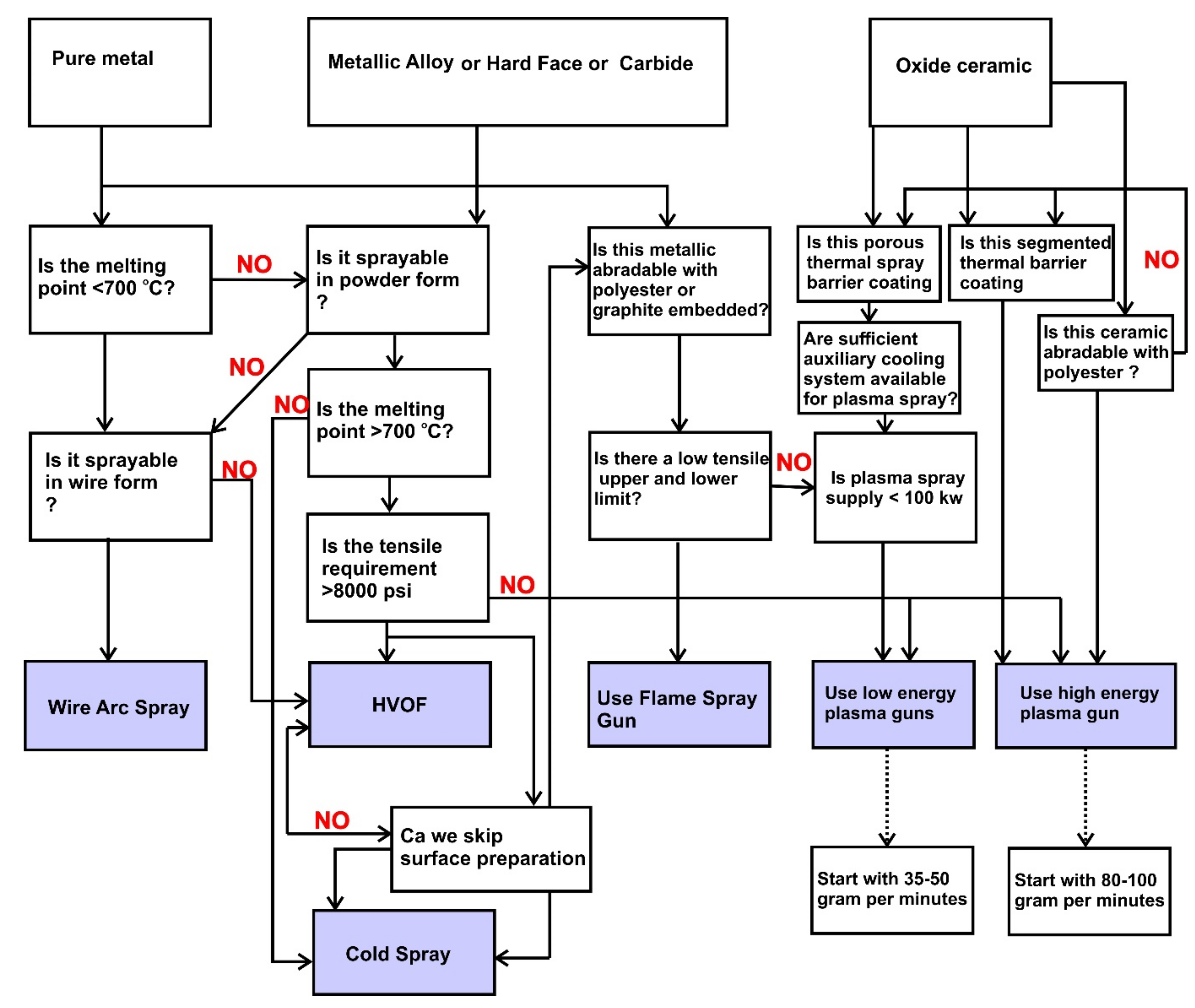
Figure 2.
Thermal spray plume showing high, medium, and low enthalpy producing gases, and suitable materials that rely on those plumes (author’s own contribution based on prior knowledge) [17,18].

Figure 3.
Enthalpy of diatomic gas vs. monoatomic gases—adapted from [19].
Figure 3.
Enthalpy of diatomic gas vs. monoatomic gases—adapted from [19].
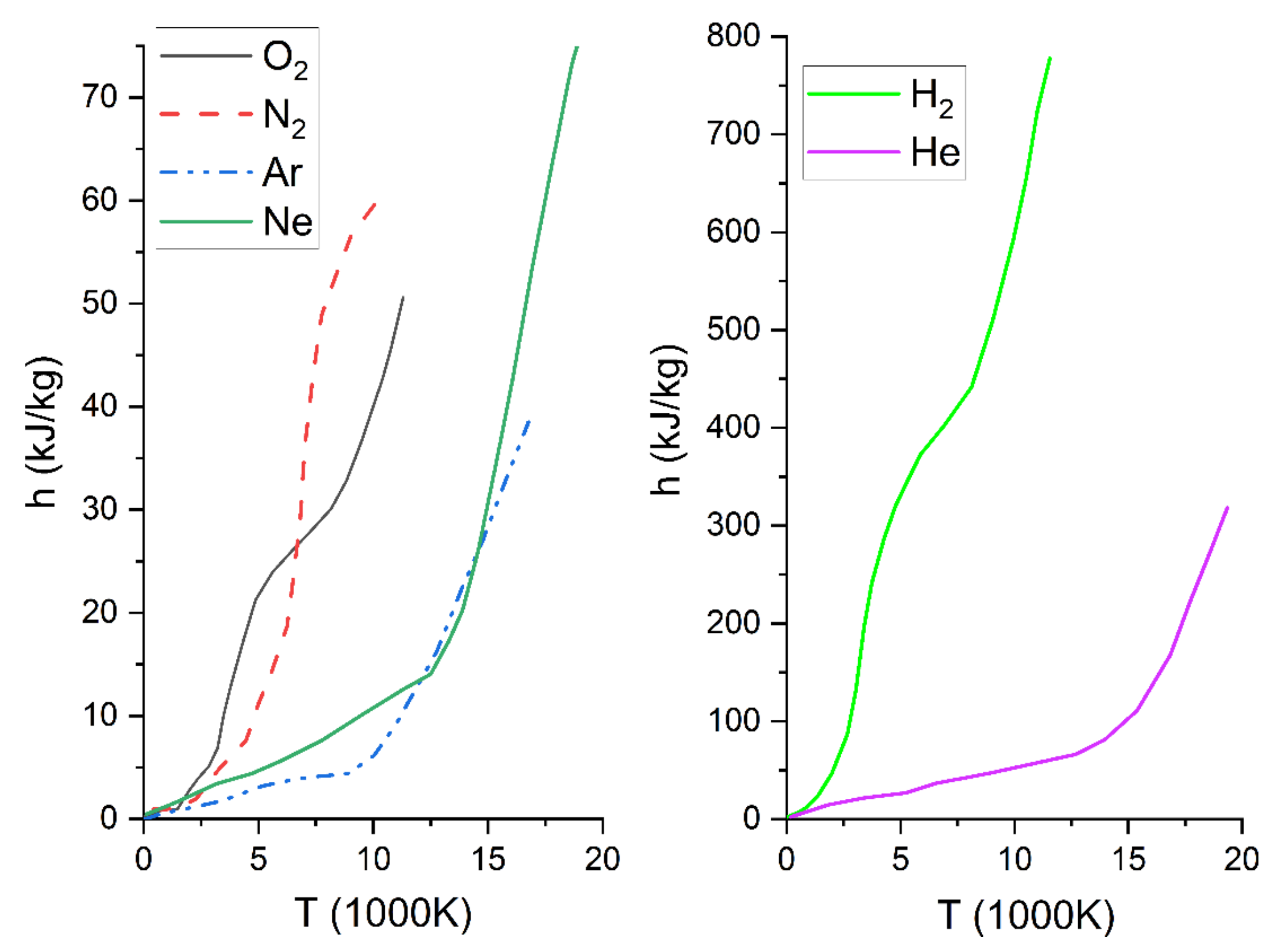
Figure 4.
Elements in the periodic table that are typically preferred for different spraying routes. Uncoloured elements are those which are yet to find their space in the thermal spray ecosystem (author’s own contribution).
Figure 4.
Elements in the periodic table that are typically preferred for different spraying routes. Uncoloured elements are those which are yet to find their space in the thermal spray ecosystem (author’s own contribution).

Figure 5.
(a) Matrix plot of parameters vs. two important coating requirements (kW and m/pass). (b) A DOE with five finalised trials with LL (low hydrogen, low spray distance), LH (low hydrogen, high spray distance), HL (high hydrogen, low spray distance), HH (high hydrogen, high spray distance), and MM (medium hydrogen, medium spray distance)—author’s own work.

Figure 6.
Histograms showing coating properties and the range of values that are expected (author’s own work).
Figure 6.
Histograms showing coating properties and the range of values that are expected (author’s own work).
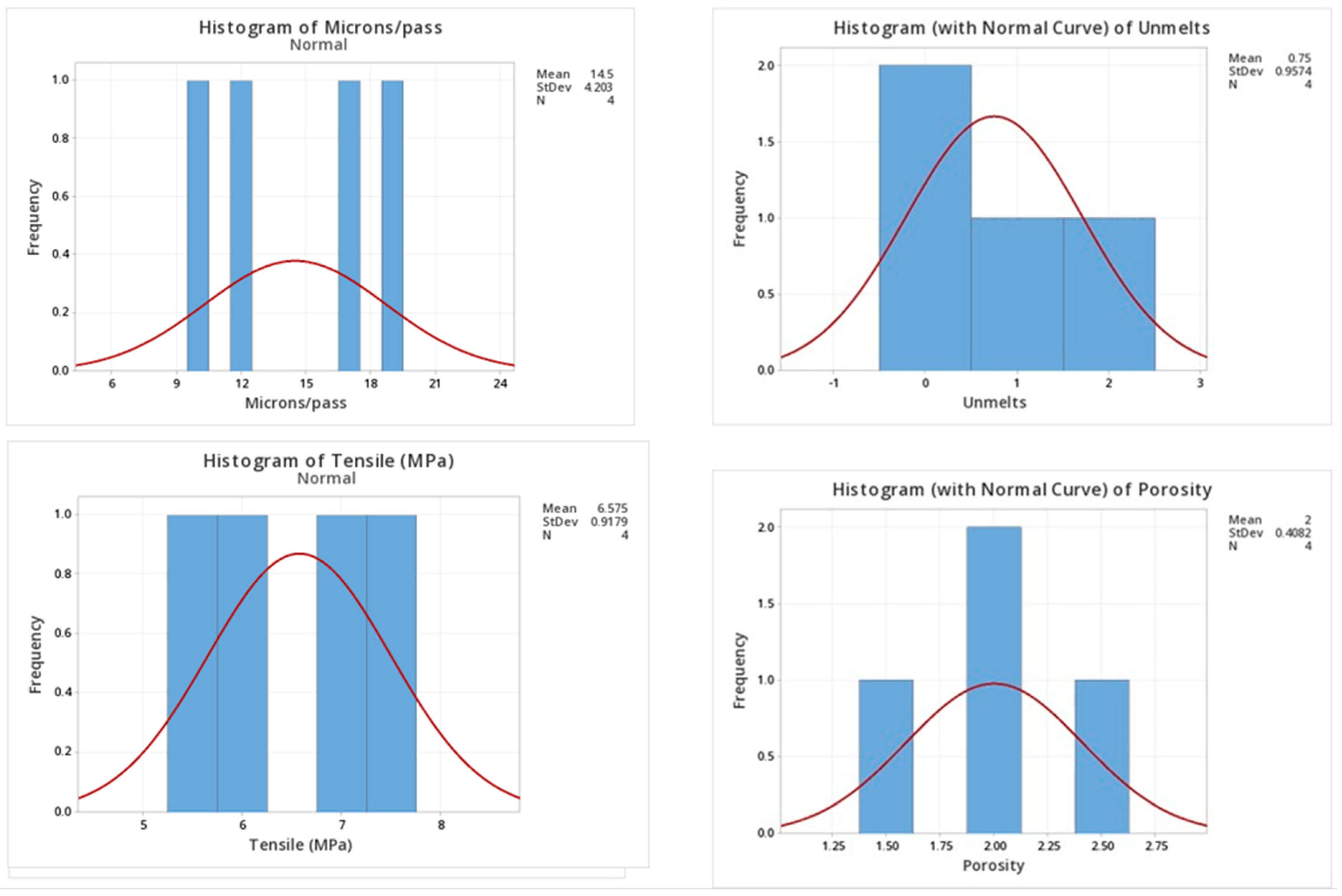
Figure 7.
Plume plate picture and how to ensure deposition efficiency during thermal spraying (standoff distance refers to the face of the nozzle in the gun) (author’s own work).
Figure 7.
Plume plate picture and how to ensure deposition efficiency during thermal spraying (standoff distance refers to the face of the nozzle in the gun) (author’s own work).
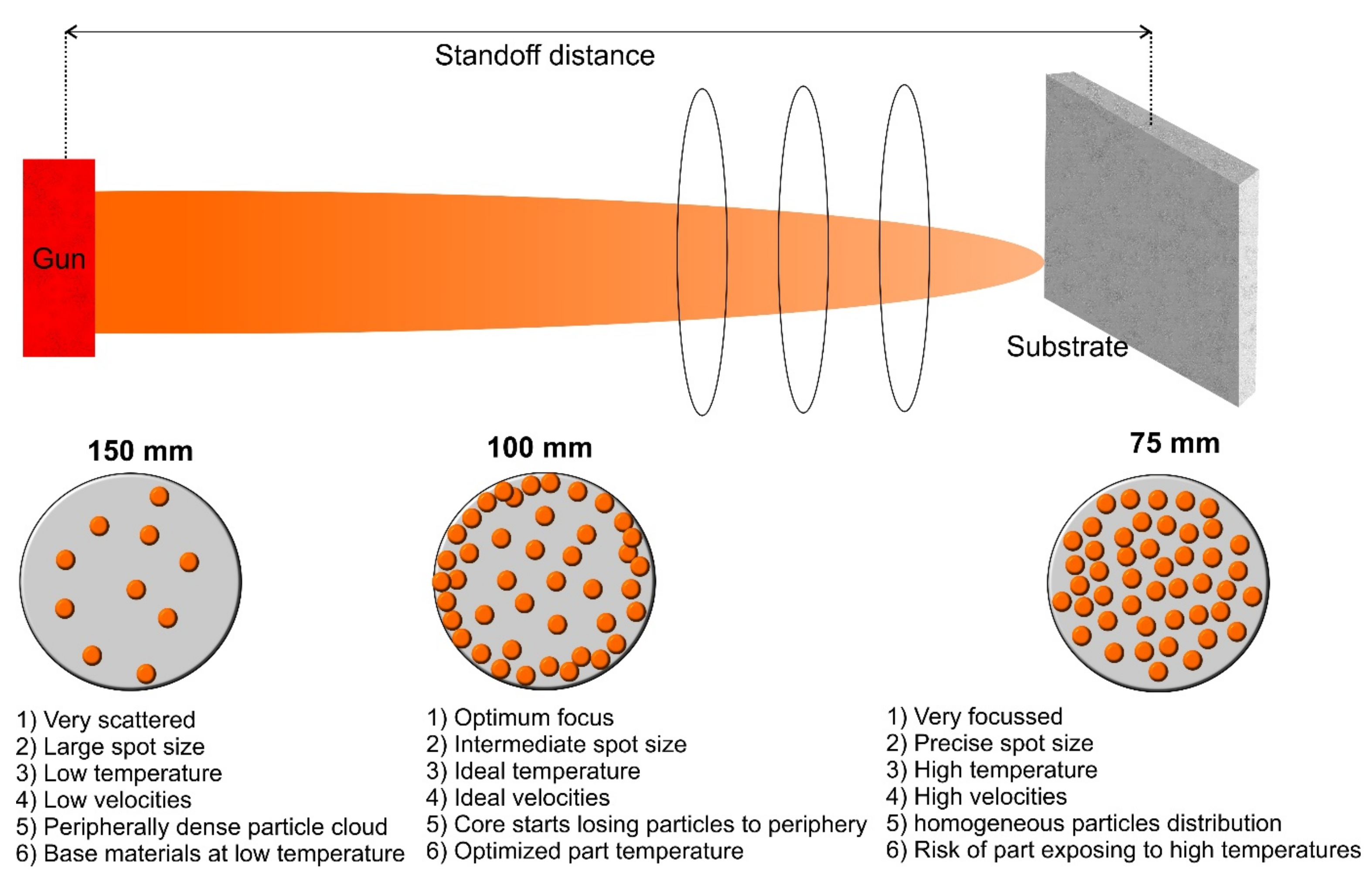
Figure 8.
Plume study on a flat plate (author’s own work).
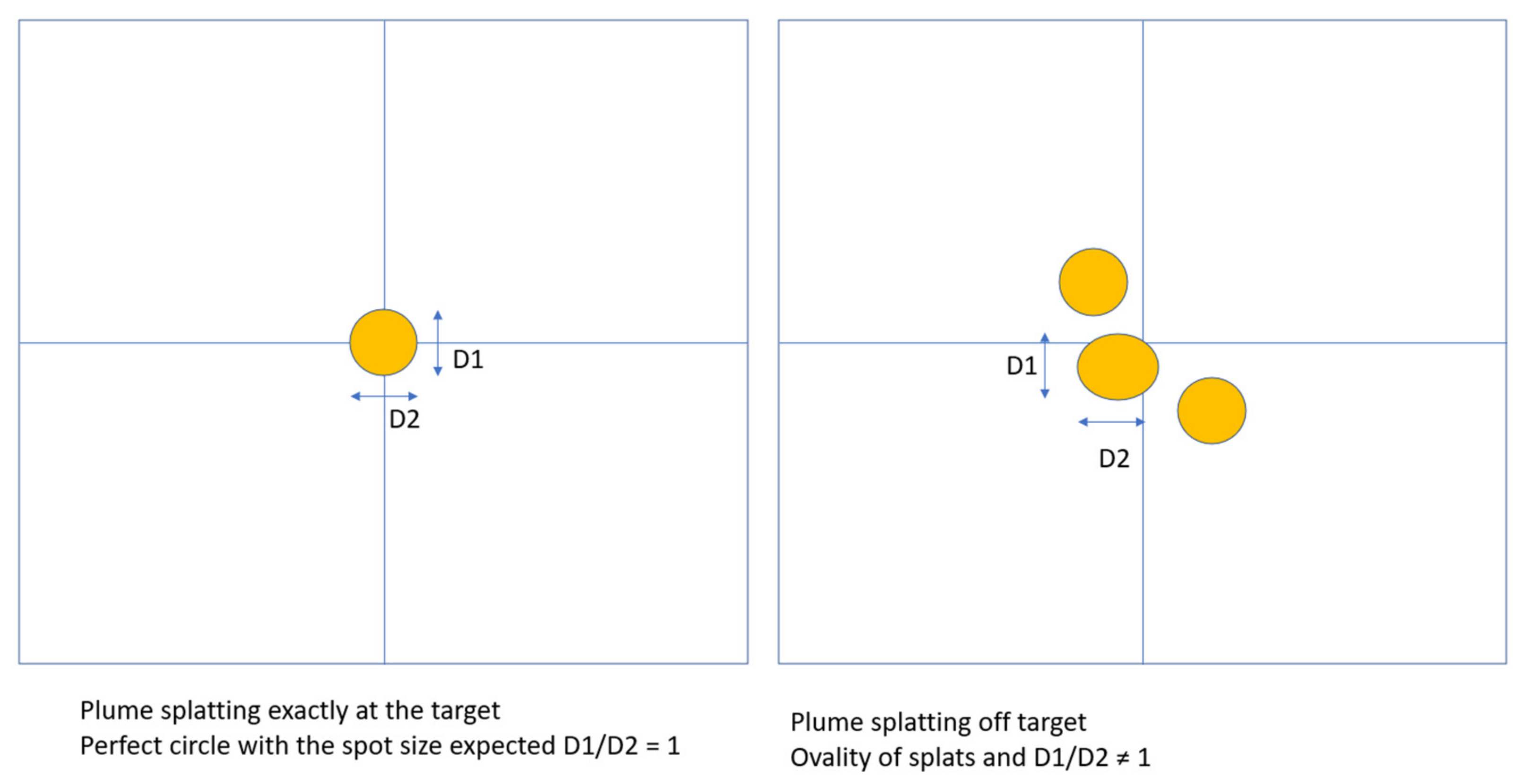
Figure 9.
Impingement of a particle with a 90° injector vs. a 75° injector. Chances of improving the residence time of the particle in the plume with a 75° injector (author’s own image).
Figure 9.
Impingement of a particle with a 90° injector vs. a 75° injector. Chances of improving the residence time of the particle in the plume with a 75° injector (author’s own image).
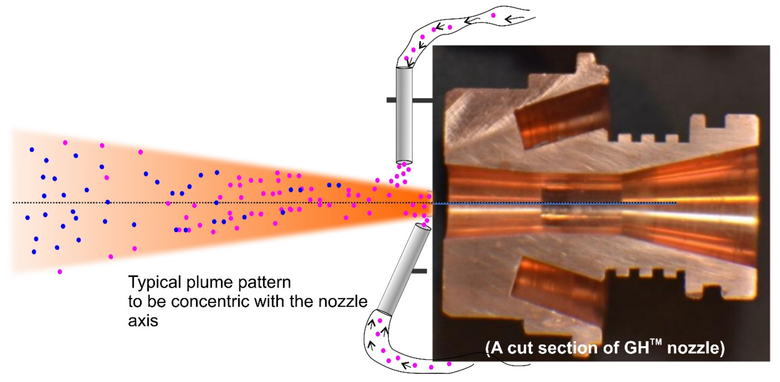
Figure 10.
The gun arsenal and their capability to produce microstructures: dense metallic bond coat (HVOF DJ2600 gun), segmented coatings (Plazjet 200 kW gun), low porous TBC (9MB gun), and high porous TBC (F4MB gun) [38,39,40,41].


| Nitrogen (SLPM) | Hydrogen (SLPM) | Standoff (mm) | Carrier gas (SLPM) | Current (Amps) | Voltage (V) | Power (kW) | Feedrate (g/min) | Unmelts | Porosity (%) | Microns/Pass | Tensile (MPa) |
|---|---|---|---|---|---|---|---|---|---|---|---|
| 33 | 1.5 | 100 | 3 | 400 | 30 | 12 | 35 | 3 | 4.0 | 10 | 5.5 |
| 33 | 2.5 | 80 | 4 | 400 | 37 | 15 | 35 | 2 | 3.0 | 12 | 6.2 |
| 38 | 4.5 | 90 | 4 | 400 | 40 | 16 | 38 | 1 | 2.5 | 17 | 7 |
| 38 | 5 | 100 | 4 | 400 | 50 | 20 | 45 | 0 | 2.0 | 19 | 7.6 |
Table 2.
Repeats of trials, to ensure that the outcome from the experiments is repeatable.
| Variable | N | N* | Mean | SE Mean | St. Dev | Min | Q1 | Median | Q3 | Max |
|---|---|---|---|---|---|---|---|---|---|---|
| Unmelts | 4 | 0 | 0.75 | 0.479 | 0.957 | 0.00 | 0.00 | 0.500 | 1.750 | 2.0 |
| Porosity | 4 | 0 | 2 | 0.204 | 0.408 | 1.500 | 1.625 | 2.00 | 2.375 | 2.5 |
| Microns/pass | 4 | 0 | 14.5 | 2.1 | 4.2 | 10 | 10.5 | 14.5 | 18.5 | 19 |
| Tensile (MPa) | 4 | 0 | 6.575 | 0.459 | 0.918 | 5.5 | 5.675 | 6.6 | 7.45 | 7.6 |
Table 3.
Effects of parameters on the microstructure and mechanical properties of a coating.
| Microstructural Feature and Mechanical Properties | Spray Distance  | Robot Speed | Off-Gun Angle (Deviating from 90°) | Primary Gas | Secondary Gas | Clean Grit Blasting |
|---|---|---|---|---|---|---|
| Oxide |  |  |  |  |  |  |
| Porosity |  |  |  |  |  |  |
| Interface Quality |  |  |  |  |  |  |
| Unmelts |  |  |  |  |  |  |
| Tensile Strength |  |  |  |  |  |  |
| Hardness |  |  |  |  |  |  |
 —Increase,
  —No Effect,
  —Decrease.
Disclaimer/Publisher’s Note: The statements, opinions and data contained in all publications are solely those of the individual author(s) and contributor(s) and not of MDPI and/or the editor(s). MDPI and/or the editor(s) disclaim responsibility for any injury to people or property resulting from any ideas, methods, instructions or products referred to in the content. |
© 2023 by the authors. Licensee MDPI, Basel, Switzerland. This article is an open access article distributed under the terms and conditions of the Creative Commons Attribution (CC BY) license (https://creativecommons.org/licenses/by/4.0/).
Share and Cite
MDPI and ACS Style
Venkatachalapathy, V.; Katiyar, N.K.; Matthews, A.; Endrino, J.L.; Goel, S. A Guiding Framework for Process Parameter Optimisation of Thermal Spraying. Coatings 2023, 13, 713. https://doi.org/10.3390/coatings13040713
AMA Style
Venkatachalapathy V, Katiyar NK, Matthews A, Endrino JL, Goel S. A Guiding Framework for Process Parameter Optimisation of Thermal Spraying. Coatings. 2023; 13(4):713. https://doi.org/10.3390/coatings13040713
Chicago/Turabian StyleVenkatachalapathy, Viswanathan, Nirmal Kumar Katiyar, Allan Matthews, Jose Luis Endrino, and Saurav Goel. 2023. "A Guiding Framework for Process Parameter Optimisation of Thermal Spraying" Coatings 13, no. 4: 713. https://doi.org/10.3390/coatings13040713
Note that from the first issue of 2016, this journal uses article numbers instead of page numbers. See further details here.