Review

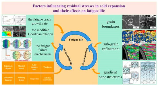
Factors Influencing Residual Stresses in Cold Expansion and Their Effects on Fatigue Life—A Review

by
Ru Su
1,
Lei Huang
1,
Changzhou Xu
2,
Peng He
3,
Xiaoliang Wang
2,
Baolin Yang
4,
Dayong Wu
1,
Qian Wang
1,
Huicong Dong
1 and
Haikun Ma
1,*
1
Hebei Key Laboratory of Material Near-Net Forming Technology, School of Materials Science and Engineering, Hebei University of Science and Technology, Shijiazhuang 050018, China
2
Oriental Bluesky Titanium Technology Co., Ltd., Yantai 264670, China
3
China International Engineering Consulting Corporation, Beijing 100037, China
4
Shijiazhuang Haishan Industrial Development Corporation, Shijiazhuang 050208, China
*
Author to whom correspondence should be addressed.
Coatings 2023, 13(12), 2037; https://doi.org/10.3390/coatings13122037
Submission received: 13 November 2023 / Revised: 28 November 2023 / Accepted: 30 November 2023 / Published: 2 December 2023
(This article belongs to the Special Issue Microstructure, Mechanical and Tribological Properties of Alloys)

Abstract

:
Cold expansion technology has been widely used in aviation industries as an effective method of improving the fatigue performance of fastener holes. It can improve the fatigue life several times over without adding weight, meeting the growing demand for lightweight and durable aircraft structures. In recent years, it has been extensively studied through extensive experiments and finite element simulations to analyze the residual stresses around the fastener hole. Appropriate process parameters lead to the generation of beneficial residual stresses that influence the material microstructure, thereby improving the fatigue life of the component. This paper summarized factors influencing residual stresses in cold expansion and their effects on fatigue life, and the strengthening mechanism, parameter optimization, and effect of anti-fatigue are discussed from the point of view of the residual stress and microstructure. The development of new cold expansion technologies and the research directions that can realize anti-fatigue technology efficiently are proposed.

Graphical Abstract

1. Introduction

Bolting and riveting are the most widely used assembly techniques in aerospace industry due to their its advantages of light weight, reliable connection and easy maintenance [1]. However, geometric discontinuity in the vicinity of the fastener holes easily leads to stress concentrations around the holes and makes the joints susceptible to failure [2]. The safety, dependability, and service life of the entire aircraft are directly correlated with the fastener hole fatigue life [3]. According to the literature, 50%–90% of structural fractures in aging airplanes are caused by fatigue fractures of fastener holes [4,5]. Therefore, improving the fatigue life of fasteners is becoming the most critical research direction in the aerospace industry [6].
The Boeing Company invented a widely utilized method for cold expansion (CE) fastener holes and employed it for the first time in the F/A-18 and other aircraft structural components in the early 1970s [7]. The CE process entails inserting a mandrel of the proper size through the fastener hole to cause extensive plastic deformation around the hole and subsequently compressive residual stress [8]. This stress reduces the stress concentration and prevents fatigue crack initiation and propagation [9]. A self-compensating annular residual compressive stress zone moves around the fastener hole after the mandrel is removed, favorably reducing the negative effects of stress concentrations on the fatigue performance of the hole structure, and the elastic zone of the material tends to return to its initial state [10]. Split-sleeve cold expansion (SCE) has been employed using elastic split sleeve to create a separation between the mandrel and the hole wall. This approach effectively enhances the extent of expansion deformation while mitigating the damage inflicted upon the hole wall by the mandrel [11]. The process needs to be one-sided, which also provides radial expansion to yield the area surrounding the hole in a repeatable and controlled manner [12,13]. SCE technology is characterized by simpler operation and a better strengthening effect. Statistically, SCE can increase the fatigue life to failure by a factor of 3 to 10, depending on the intensity of the fatigue stress [14]. SCE technology has become a widely accepted method of improving the fatigue strength of pore structures. Based on the above advantages, SCE technology has been widely used for the strong treatment of wing-to-fuselage joint holes, as well as bolt holes on the underside of wings and other major aircraft structural components.
Numerous scholarly researchers assert that the enhancement of fatigue resistance in fastener holes primarily stems from the presence of residual compressive stress [15,16], and the residual stress around the fastener hole after CE has been studied through a combination of experiments and finite element simulation techniques based on existing theories. Fu et al. [7] proposed the development trend and new research direction of anti-fatigue effect based on the research of CE technology in the past two decades and the needs of the new generation of aircraft manufacturing. However, the main factors influencing the residual stress and fatigue life were not summarized in detail. This paper reviews the current state of research on CE processes, including the methods of measuring residual stresses around fastener holes, and the effects of CE processes on material microstructure and cracking. Residual stresses are influenced by various factors and are controlled by variables to limit them and improve the fatigue life of the component. The content of this paper can elucidate the CE process from the perspective of microstructure and fatigue crack rate, and elucidate the reinforcement mechanism of the CE process. Finally, the state of development of the new CE process for the height requirements of modern aircraft is summarized and three new research directions for CE technology are proposed.

2. Measurement Methods for Residual Stresses

The material surrounding the fastener hole is plastically deformed by the CE process, which increases the number of stress cycles before a part fails and produces compressive residual stresses [17]. Appropriate residual stresses can be a beneficial factor in strengthening the material, whereas inappropriate residual stresses can lead to fastener fracture. This means that there is usually an optimum range of beneficial residual stresses, beyond which material properties deteriorate and fastener life is reduced. Similarly, the delay in crack propagation is significantly impacted by the drop in stress intensity factor brought on by residual compressive stresses. It is essential for preventing crack initiation and propagation [18,19,20]. Both the magnitude and distribution of residual stresses affect the fatigue resistance of the fastener. Therefore, residual stresses are important in the study of CE technology.

2.1. Experimental Measurement Methods

Due to the increased stress concentration at the hole brought about by the CE process, the accurate determination of the compressive residual stress field has been the subject of numerous experimental investigations. Research on residual stress testing methods dates back to the 1930s, and in the earliest studies, residual stresses were not measured explicitly [21]. As technology advanced, measurement methods gradually improved and diversified into a variety of test procedures [22]. Traditional testing methods can be broadly divided into two categories: mechanical release testing methods and non-destructive testing (NDT) methods [23,24]. Standard mechanical release test methods include drilling, the ring core method, indentation, etc. [25,26]. Standard NDT methods refer to physical methods including X-ray diffraction, neutron diffraction, the Garcia–Sachs method, etc. [27,28]. X-ray measurements mainly measure residual stresses at the surface of the material [29,30]. The tensions in the irradiated volume are inevitably averaged out by the experimental X-ray approach. Therefore, it is impossible to eliminate the significant stress gradients near the hole. The Garcia–Sachs method is used to determine the residual stress by measuring the relaxation of the material around the hole using strain gauges [31]. NDT methods have been shown to be applicable to residual stresses introduced by selected manufacturing processes and to monitor the distribution of residual stresses induced by fatigue loading [32,33]. Matvienko et al. [34] proposed a new destructive method to quantitatively assess the accumulation of fatigue damage in the stress concentration zone near CE holes accompanied by the effect of residual stresses. Veticheti et al. [35] proposed a new method based on hall coefficient measurements, a type of electromagnetic non-destructive testing technique, for assessing residual stresses on treated material surfaces. Schajer et al. [36] introduced five different residual stress measurement methods and their measurement principles, advantages and disadvantages. Five difficulties encountered during the measurement process are also suggested. The standard distribution of residual stresses around the CE fastener hole, as determined by these methods, is generally consistent even though the precision and measuring techniques differ. Figure 1 depicts the typical distribution of tangential residual stresses at the CE fastening hole. The graph shows that the peak compressive stress is situated at the hole edge and is close to the material compressive yield strength. Compressive stresses are balanced by residual tensile stresses that are between 10% and 15% of the material tensile yield strength and are located far from the hole.

2.2. Numerical Simulation Method

In the CE process, the fastener hole undergoes a plastic deformation process. The further away from the hole, the greater thfe tendency towards elastic deformation, and with the increase in time, all of it turns into plastic deformation. As a result of the plastic deformation caused by pressing into the specimen, the unloading of the specimen at the end of the test will inevitably leave pits around the hole, and residual stresses will inevitably be present in the pits. None of the aforementioned techniques can be used to assess the residual stresses in the crater due to the local character and complexity of the hole. The finite element method (FEM) can be used to investigate the residual stresses around the fastener hole, which allows the visual observation of the distribution of and variation in stress clouds during CE [38]. Numerical simulations can produce precise residual stress distributions by using logical mesh design, material attributes, contact circumstances, boundary conditions, etc. There is a distinct difference between the findings of the numerical simulation of the circumferential residual stresses and the actual results, as shown in Figure 2, which compares the results of the circumferential residual stress calculations with those of the experiments. There are two reasons for this discrepancy. Firstly, based on the CE technique, the fastener hole is enlarged to its final size after CE, causing the release and redistribution of residual stresses around the hole; unfortunately, the effect of this process is neglected in the FEM. Secondly, the FEM-estimated loading and boundary conditions are closer to the ideal. In comparison, the non-axisymmetric residual stress distribution around the hole indicates that the actual loading and boundary conditions are more complicated [39].
FEM is usually performed using 2D and 3D models to simulate the CE process, which is analyzed using the numerical code ABAQUS. The 2D models agree with the experimentally measured mean through-thickness residual stresses, but no significant through-thickness variation can be calculated [31]. The choice of mesh size and layout is critical in finite element analysis. Unfortunately, this kind of analysis would take a lot of computer time. The closer the mesh is to the fastener hole, the better the outcomes will be without consuming an excessive amount of computer time. Prior to running the simulation, each material’s characteristics, including its ultimate yield strength, Young’s modulus, and Poisson’s ratio, must be determined. The simulation results show that the tangential residual stresses at the edges of holes of different thicknesses are not uniformly distributed. The residual compressive stress at the hole edge changes throughout the thickness direction, with the entry face having the lowest residual compressive stress and the hole edge towards the mid-plane having the highest residual compressive stress [37].
Both experimental measurement methods and numerical simulation methods can detect residual stresses in components. Both methods have a focus, and it is desirable to combine them to verify the measurements against each other. The main factors influencing residual stresses are the parameters of the process itself. Section 3 mainly discusses the influence of the process parameters on residual stress.

3. Factors Influencing Residual Stresses

Understanding the variables that determine residual stresses is crucial to prolonging the service life of components since residual stresses can shorten their lifespan [40]. Essentially, the causes of residual stresses can probably be divided into three categories; the first is non-uniform plastic deformation, the second is temperature variation, and the third is non-uniform phase change [41]. The strengthening effect of the CE process depends on reasonable process parameters, mainly including the degree of expansion, mandrel speed, initial hole diameter, thickness, edge distance ratio, reaming degree, etc.

3.1. Expansion Degree

The expansion degree is one of the most critical process parameters in the CE process, and directly affects the amount of fatigue gain achieved by this process. If the degree of expansion is too small, the tightening of the hole around the formation of a certain depth of residual compressive stress layer will not strengthen the effect; The degree of expansion is too large and will cause many problems, such as SCE being used to cause an increase in the flow of metal in the direction of the axis of the hole, so that the expansion exit surface has a significant bump. The expansion between the hole diameter and the mandrel maximum diameter is referred to as the expansion degree:
E a = ( D + 2 t 0 ) D 0 D 0
where D is major mandrel diameter, t0 is sleeve thickness and D 0 is beginning hole size.
Liu et al. [42] determined the residual stresses by finding that mandrels of different radii produce different expansion degrees for the aluminum alloy LY12-CZ. Geometric non-linearities were taken into account to determine residual stresses for mandrels without frictional contact with the hole surface. The simulation findings demonstrate that when the quantity of extrusion increases, the maximum values of tensile and compressive stresses in the radial and circumferential residual stresses steadily rise. According to the residual stress distribution curve for 2024-T3 aluminum alloy that Kumar et al. [38] obtained using finite element analysis, the tangential residual stress at the hole edge that corresponds to the 5% expanded hole was 14% higher than that of the 3% expanded hole and was 6.36% higher than that of the 4% expanded hole. Even though the expansion degree can be adjusted to greater levels, there is a certain threshold of expansion beyond which advantageous results are not evident due to strong frictional forces and surface upsetting problems connected to mandrel tugging [43]. According to Ghfiri et al. [44], drilling a hole while expanding can postpone the initiation and propagation of new cracks, and fatigue life is enhanced by increasing SCE. However, despite the high value of CE degrees, the projected benefits of CE were not realized in the experimental study for the two aluminum alloys, 6005A-T6 and 6082-T6 [18]. The local zone surrounding the hole may have been harmed during the CE process at these high values, which is one potential explanation. Figure 3 shows the variation in residual stress for different alloys at different expansion degrees, and Table 1 lists the expansion parameters and the fatigue life improvement multipliers obtained for the material in the CE process. The applied expansion for fastener hole diameters in aluminum typically varies from 3 to 6 percent. The applied expansion range for titanium is 4.5 to 6.7 percent. There will be numerous deep microcracks in the boss after expansion if the expansion degree is too high, which will result in a reduction in fatigue strength; there will be few deep microcracks in the boss after expansion if the expansion degree is too low, which will have the opposite effect [43].
Table 1. The material expansion and fatigue life.
MaterialThe Expansion DegreeFatigue Life ImprovementRef.
D16chT2.7%6.6 times2022 [11]
2A12T46%6 times2008 [3]
AA6061-T64%2.47 times2017 [10]
7075-T64%9 times2023 [45]
7050-T74514%3 times2022 [33]
TC44%1.7–2.2 times2015 [39]
Railway steel4%2 times2022 [46]
AZ31B6%4 times2023 [47]

3.2. Mandrel Speed

When the fastener hole expands, the expansion bar is required to uniformly and continuously squeeze through the hole wall, so that the hole wall is completely deformed; pauses and intermittent and impact stroke phenomena should not be allowed in the expansion process. Otherwise, it will be easy to cause open seam-sleeve expansion in the sleeve fold, resulting in jamming and the broken rod phenomenon. Farhangdoost et al. [48,49] analyzed the impact of various mandrel speeds on the distribution of residual stress around the fastener hole. As depicted in Figure 4, the fatigue life of the fastener hole increases with increasing mandrel speed and residual stress around the hole.

3.3. Edge Distance Ratio

Typically, a ratio of e/D is used to determine the edge distance ratio (EDR). D is the hole diameter, and e is the distance between the hole center and the plate’s undamaged edge. Due to residual stresses produced by CE and the interaction of the fastener with the unstressed edges of the plate when the edge distance is minimal, the tangential residual stress distribution around the fastener hole is no longer symmetrical to the hole center. Liu et al. [50] found that when the EDR of TC4 titanium alloy specimens was reduced, the residual tangential compressive stresses in the CE hole decreased and the fatigue life was reduced. Figure 5 shows the distribution of residual stresses for different EDRs at different expansion degrees and different hole margins. As the edge distance decreases relative to the EDR, the residual tangential compressive stress at the hole edge decreases. CE slows the fracture propagation as intended at all edge ratios. This delay is brought on by a decrease in the stress intensity factor of the fractures produced by the cold expansion holes. As a result, Fatigue Technology Inc (FTI) recommends 1.75 as the minimal e/D limit [51]. The residual stress field has no impact if e/D is higher than 3 [52].

3.4. Thickness

The plate is expanded layer by layer from the inlet side to the outlet side during the drawn mandrel CE as the mandrel gradually interacts with the fastener hole. When the mandrel is fully engaged with the hole, the fastener hole experiences unequal expansion along the thickness of the plate as a result of differences in the constraining conditions [53]. Depending on which way the mandrel is being pulled, each layer experiences a variation in axial strain as a result [37]. Due to this expansion behavior, the residual stresses generated by the fastener holes will be completely non-uniform along the thickness. Stuart et al. [54] used the contour method to measure the two-dimensional residual stress distribution in CE along the crack plane of 7075 aluminum alloy. It was found that the residual stress levels were higher in the mid-thickness of the specimen and lower in compression at the surface; the thickness-averaged residual stresses compressed in the first 2 mm at the edge of the hole and then shifted to tensile residual stresses. According to the available literature, the residual stresses due to the CE of the fastener holes are higher in the middle part of the thickness, and lower compressive residual stresses are generated at the surface (Figure 6). Due to the asymmetry of the residual stress field across the thickness of the plate, two–dimensional simulations of cold forming cannot accurately estimate the residual stress field [53]. According to the investigation, the compressive residual stresses for SCE fastener holes, in particular, achieved their maximum values and become more compressive with increasing plate thickness for a certain degree of expansion [55].

3.5. Initial Hole Diameter

In the SCE process, as most of this process is used in a one-time expansion process, when the expansion is over, the material after elastic-plastic deformation, elastic deformation release, or even reverse yielding phenomenon should be calculated. After the selected expansion amount, the accurate knowledge of the amount of material rebound, to set the hole diameter of an expansion, is needed to achieve the basic assembly requirements. The service life increases as the diameter of the hole increases. This outcome is well known because fracture retardation occurs when the hole diameter rises and the stress concentration factor kt falls, reducing the driving power for crack initiation (Figure 7a,b) [18]. Yasniy et al. [56] found that for the same degree of CE, the increase in hole diameter was accompanied by an increase in the plastic deformation of the metal around the hole, partially increasing the residual stress. For various hole sizes and CE levels, a relationship exists between the stress range or maximum stress at the edge of the hole on the specimen inlet side and the fracture initiation life.

3.6. Reaming

The diameter of the hole can also be changed by reaming. During the SCE process, the material is plastically deformed by the force at the large end of the mandrel and the metal is expanded at the open seam, resulting in an axial convex ridge in the wall of the fastener hole. This is usually carried out by reaming to remove the convex ridges in the hole to bring the hole size up to the assembly requirements. Proper reaming of the hole wall can correct the roundness of the hole and remove potential fatigue micro-cracks, ensure the continuity of hole collection and micro-continuity, and improve the fatigue life of the hole [57]. However, the removal of the material will inevitably change the elastic-plastic state of the pore wall material, thereby affecting residual stress and microstructure, as shown in Figure 7c [58]. Figure 7d shows the effect of different reaming amounts on the residual stress distribution. It can be seen that after reaming, the compressive residual stress along the radial direction of the hole edge shows a trend of increasing and then decreasing, and the compressive residual stress gradually decreases with the increase in the reaming amount. Therefore, the proper amount of reaming will result in maximum residual stress around the fastener holes, thereby maximizing fatigue life.

3.7. Temperature

The improvement in the cold expansion holes’ fatigue life is significantly influenced by temperature. The residual stress caused by the CE of fastener holes can be relaxed by exposure to temperature alone. The strengthening effect is typically weaker at high temperatures than it is at room temperature [59]. The higher the residual stress, the greater the relaxation [60,61]. Under cyclic temperature changes, the tendency of temperature changes to neutralize local peak residual stresses occurring at the surface results in a slight diffusion of in-homogeneous residual stresses at the edge and depth of the hole, thereby improving fatigue resistance [62]. Clark et al. [63] found that stress relaxation over time occurred in 7050–T7451 aluminum plates at 104 °C, resulting in a 13.6% reduction in residual stress after 250 h and a 17.3% reduction after 5000 h. The temperature dependence of the relaxation rate shows that the fatigue life does not increase at slightly higher temperatures, and residual stresses decrease dramatically. In addition, Wang et al. [64] have shown that a relatively stable residual stress field at high temperatures promotes fastener life extension. According to Figure 8, after the first cycle, the compressive residual stresses marginally rise, producing a hardening effect from a single deformation. The dislocations continue to shift and are removed after ten cycles under external loads. A cyclic softening effect is created by a decrease in the system plastic deformation energy, dislocation density, and residual compressive stress. The leftover compressive stress can be kept steady by additional cyclic loading. The sum is less than the elastic limit after work hardening and the plasticity increases because of the preceding work hardening effect. Chakherlou et al. [65] investigated the effect of high temperature exposure on the residual stress distribution in CE fastener holes. According to the findings, creep stress relaxation took place after a 50 h exposure at 120 °C. Thermal cycling re-distributed the residual stresses across the thickness, lowering the initial peak at the intermediate margins. For CE specimens, high heat cycling reduces fatigue life. This is thought to be brought on by a weakening of residual tensions in close proximity to the hole center. Although CE specimens treated to mild thermal cycling experienced a reduction in residual stress, it has been discovered that these specimens nonetheless had a longer fatigue life than CE specimens [66].

3.8. Multi-Hole Construction

Parts of aircraft have numerous fastening holes spaced out regularly. In such circumstances, the nearby holes may have an impact on the residual tensions following CE. The CE sequence may also have an impact on the variety of residual stresses in this series of holes [67]. The proximity of adjacent holes is usually given as the ratio of the hole spacing, i.e., the center-to-center distance between the holes, to the hole diameter. Due to inadequate material between the holes, the CE process is ineffective around neighboring holes if the hole spacing is less than two times the hole diameter [68]. Due to the lack of material between adjacent holes, the CE of closely spaced holes would cause the introduction of residual tensile stresses, which would negatively impact fatigue performance. In contrast, the residual stresses around a hole caused by CE are unaffected by the residual stresses of the neighboring CE hole when the distance between the holes is larger than five times the diameter of the hole [67]. This hole spacing influence shows that in order to obtain the ideal CE level, it is vital to take the next hole effect into account. Seifi [69] investigated the effect of hole CE on the crack initiation cycle and fatigue life of two adjacent hole plates and showed that the CE process induced compressive residual stresses around the CE holes and reduced the crack expansion rate under applied load, resulting in an increase in crack initiation cycle and total fatigue life of 100% and 86%, respectively.
Among the above eight factors, the expansion degree is the parameter that has the greatest influence on the CE process; reaming is the parameter that has the least influence on the CE process. All of these factors can be used to improve the fatigue life of a component by changing the residual stress. However, most researchers have studied only one or two variables and have not proposed a multi-variable research program. In Section 5.1, the authors propose the use of FEM to simulate multiple variables to better improve the fatigue life of materials.

4. The Effect of Cold Expansion on Fatigue Life

Both residual stress and microstructure can affect the fatigue strength of components. Residual compressive stresses inhibit fatigue crack initiation and propagation; the CE process produces plastic deformation, resulting in grain refinement, increased slip and dislocations and improved fatigue strength of the component. This section summarizes in detail the effects of residual stress and microstructure on fatigue performance.

4.1. Effect of Residual Compressive Stress on Fatigue Life

The mechanism by which CE promotes crack initiation and propagation is through the CE process generating a residual compressive stress field that lowers the stress intensity factor around the hole relative to the stress intensity factor for cracks in no cold expansion (NCE) holes [70,71].
At an early stage, the fatigue crack growth (FCG) rate can be given by:
d a d N = A · ( Δ K Δ K O P ) m
where A and m are materials parameters, Δ K is the stress intensity factor range and Δ Kop is the crack opening stress intensity factor range. The stress intensity factor range can be calculated by [72,73]
Δ K = A · [ Δ σ · ϕ s e c ( π · ( α + r ) w ) · π · α · F ] m
where ϕ accounts for the increase in stress near the hole due to the presence of the hole, α is the fracture length determined from the hole edge, r is the radius of the hole, F is the elastic-plastic correction factor and w is the width of the plate, which can be given by
F = 1 2 ( s e c π 2   σ m a x σ y + 1 )
Synthesizing Equations (2)–(4), the crack propagation rate can be given by
d a d N = A · [ ( σ m a x Δ σ o p ) · ϕ s e c ( π · ( α + r ) w )   · π · α · 1 2 ( s e c π 2   σ m a x σ y + 1 ) ] m
Figure 9 displays the crack extension rate da/dN as a function of the different stress intensity components. This comparison unequivocally demonstrates that the crack propagation rate of the CE specimen consistently remains lower than that of the NCE specimen. Due to the residual compressive stresses created by the CE process, which raise the crack open stress intensity factor, the effective stress intensity factor drops [74]. It is suggested that the CE process has a more substantial damping effect on the crack propagation rate when the Δ K value is low.
In recent years, it has been possible to use the modified Goodman relation, as shown in Equation (6), to explain the impact of residual compressive stress on delaying the onset of the fatigue crack. This relationship denotes a linear relationship between stress amplitude and mean stress regardless of the microstructure effect, where σ f is the fatigue endurance of the material under fully reverse loading, σ m is the mean stress due to the external applied load, σ b is the ultimate tensile strength of material, and σ a is the equivalent fatigue strength. As a result, fatigue would rise along with the rise in residual compressive stress ( σ R ), extending the fracture initiating life.
σ a = σ f ( 1 σ m + σ R σ b )
The effect of residual compressive stress on the FCG rate at this point can be analyzed using the Paris equation, as shown in Equations (7) and (8):
Δ σ e f f = σ m a x σ o p
Δ k e f f = k m a x k m i n = f Δ σ e f f π α
d a d N = C ( Δ k e f f ) m
where Δσeff is the effective stress amplitude, σmax is the maximum applied stress, σop is the threshold value of crack opening stress, Δkeff is the stress intensity factor amplitude, kmax and kmin are the maximum and minimum stress intensity factors at the crack, f is a function of component geometry and crack size, a is the crack length, da/dN is the crack growth rate and C and m are material constants. It is obvious that the residual compressive stress, which is treated as a special static, means that stress could minimize the effective stress amplitude Δ σeff, and then result in a decrease in the effective stress intensity factor Δ keff at the crack tip and evidently, at last, slow down the FCG rate [74]. The striation spacing reflects the FCG rate accurately under cyclic load [30]. As a general rule, a smaller striation spacing corresponds to a lower FCG rate [75,76]. However, the striation spacing is non-uniform owing to complex influencing factors such as the microstructure and load applied. Thus, for an FCG rate in a particular region, an average striation spacing is usually adopted for representation. The stress value aligns with the striation spacing; the greater the stress value, the smaller the striation spacing, as shown in Figure 10. The stress distribution state of the CE specimen during a fatigue test might therefore be interpreted to have been successfully altered by the residual compressive stress produced by CE, leading to an effectively delayed FCG rate compared to the NCE specimen. Yan et al. [74] found that the SCE treatment of TC4 produced significant compressive residual stresses that retarded the rate of crack propagation, resulting in a three-fold increase in fatigue life.
Figure 11 shows that while the crack front of the CE hole is quite uneven, the fracture surface of the NCE hole is regular. Due to the impact of tangential compressive residual stress, the fracture for CE holes expands more slowly down the hole than away from the hole. Because of their propensity to cancel out with the stress brought on by external loading, compressive residual stresses are advantageous because they lower the effective stress concentration at the hole edge [4]. Because the tangential compressive residual stresses on the drilling path of the CE hole increased with time, the crack’s ability to spread was slowed or prevented altogether. However, the SCE specimen is located at the hole entrance, where the strengthening impact is minimal [45]. The material fatigue life is strongly impacted by residual stress, according to Kattoura et al. [77]. It alters the specimen stress state when paired with the fatigue load, which reduces the initiation and growth of fatigue cracks. As a result, the SCE specimen crack started at the hole inlet side, where residual stress was minimal. Additionally, the lengths of the transition area and the major crack extension area were both longer than those of the NCE specimens. This shows that the SCE specimens can withstand more fatigue cycles and have a longer fatigue life.
Both the beginnings of cracks and the delay in the propagation of cracks are significantly influenced by the magnitude of plastic deformation brought on by compressive residual stress [18]. The magnitude of the plastic deformation after the compressive residual stress that has been decreased by relaxation treatment or fatigue loading determines the fracture propagation delay. With increasing distance from the hole edge, the material plastic deformation lessens [77]. The compressive residual stress brought on by SCE may dramatically lessen crack initiation and propagation during fatigue testing when the material is under less stress (Figure 12). When under increasing stress, the fast release of residual stress at the holed root results in a subtle improvement in fatigue life. Additionally, the substantial plastic deformation created at the holed root under the greater stress level makes it harder for the plastic layer to block fatigue fracture [59].

4.2. The Effect of Microstructure on Fatigue Life

Numerous dislocations are produced as a result of the CE process in plastic deformation. As the degree of deformation rises, slippage and an increase in dislocation density take place. When dislocation lines encounter defects, particles and other obstacles, dislocation entanglement occurs and dislocation walls are formed. Faghih et al. [47] found that at high CE concentrations inter-granular defects were found in the microstructure. Defects are present because of generated excessive plastic deformation, which causes grain slippage [78]. Dislocations gather along grain boundaries or nanoprecipitation during expansion due to the significant plastic deformation surrounding the fastener hole, which hinders dislocation mobility and stops additional plastic deformation, increasing hardness.
In addition, grain boundaries (GB) can inhibit short crack extension, and changes in the crystal orientation of adjacent grains can lead to the tilting of the crack face [47,79]. Figure 13 divides the GB into six regions and illustrates the effect of changes in GB and adjacent grain crystal orientation on FCG for AA6061-T6 holes. If the favorable slip plane of the adjacent grains is essentially in the same plane, the crack can be transmitted directly or indirectly from one grain to the other. On the other hand, if there is a deflection angle in the favorable slip plane of the adjacent grains, this can lead to tilting of the crack plane. Obviously, crack tilting or distortion favors FCG closure, resulting in longer fatigue life [78].
As demonstrated in Figure 14, there is a clear deformation structure in the surface area on both sides, which is no longer the original recrystallized grain. Grain refinement is visible at the location of the expansion holes. As shown in Figure 14a–c, in contrast to the large grains distant from the SCE holes, which remain unchanged, a significant number of LAGB are produced within the large grains close to the fastener holes, generating fine sub-grains [19]. During grain refinement, more grain boundaries and sub-grain boundaries are created. These grain boundaries can stop fatigue cracks from spreading and significantly enhance fatigue performance [80]. Particularly in the X-direction (Figure 14d,e), the wall around the holes in SCE underwent extensive sub-grain refinement, resulting in the formation of numerous grain boundaries. Short crack growth may be hampered by these grain boundaries. A limited amount of plastic deformation will occur with hindered dislocation buildup if the dislocation slips to the grain boundary and is prevented by the grain border [10].
SCE treatment produces a gradient effect on grain refinement [44]. The formation of the gradient layer is associated with diverse plastic deformations at different depths in the SCE process. During deformation, dislocation slip is primarily responsible for the particle refinement that increases the strength of the material and improves its resistance to fatigue crack initiation [82,83]. The construction of the gradient nanostructure using the SCE approach is shown in Figure 15. The gradient structure can effectively prevent the spread of cracks [84].

5. Challenges and Future Trends

The CE process technology has drawn increased attention in recent decades. It makes sense to decrease the stress concentration around fastener holes, postpone the initiation and propagation of fatigue cracks, and lengthen the fatigue life of aircraft components. However, with the advancement of technology and modern developments, the aerospace field has made higher demands on CE technology. Whether through an airframe manufacturer requiring finer components or by applying new materials to an aircraft, increasing the fatigue strength of the CE process is a necessity. Based on the above analysis, three research directions for the CE process are proposed.

5.1. Application of Finite Element Simulation

As was already noted, FEM is frequently used in the CE process to calculate the specimen fatigue life and evaluate the residual stress around the fastener. However, FEM was not used in the prior research to establish the relationship between residual stress and its affecting elements. It is necessary to establish a simulation system to obtain the optimal fatigue life of the specimen by simulating various influencing factors, such as expansion degree, edge distance ratio, friction, thickness, etc., and uniformly placing these factors in this model, as shown in Figure 16a. These variables have an impact on residual stress, which is followed by the identification of the mechanism underlying residual stress and fatigue cracking. Finally, material characteristics, residual stress, and loading force are combined in a simulation model to project the fatigue life of CE specimens. In this case, the influencing factors can be selected by using orthogonal experimental methods to select the optimal parameters. Li et al. [59] proposed a dual-scale model that takes into account the effects of residual stresses and plastic layers by combining two typical plasticity theories, the Chaboche model and crystal plasticity. Figure 16b depicts the frameworks at the macro- and micro-scales. The model can be combined with a simulation modeling system to more accurately predict the fatigue life of CE specimens.

5.2. Development of New Materials

Aluminum alloys have high corrosion resistance through various surface treatments and are the preferred choice for many commercial aircraft, as shown in Table 2 [85]. For aluminum alloys, it is crucial to increase the density, strength, Young’s modulus, fatigue resistance, fracture toughness and corrosion resistance [86]. The material properties of aluminum alloys can be altered by the addition of suitable reinforcing materials, resulting in a combined material that performs even better than its separate parts [87]. The use of aluminum alloy composites as fasteners may extend their fatigue life. However, there is currently no relevant literature on aluminum alloy composites as fasteners. Therefore, experiments need to be carried out to analyze the strengthening mechanism and strengthening effect of holes in aluminum alloy composites.
Due to their exceptional fatigue, oxidation, and corrosion resistance, nickel-based high-temperature alloys are frequently utilized in the production of aero-engine and gas turbine blades in addition to aluminum alloys [88,89]. Nickel-based high-temperature alloys can also be used as fastener materials, but the existing literature does not contain specific fatigue gains and study mechanisms for this alloy in the SCE process.
Table 2. Percentage of aircraft material applications [90].
Mass (%)Various Commercially Available Aircraft
B747B757B767B777B787A300B4
Aluminum817880702077
Steel131214111012
Titanium4627154
Composite13311504
Misc.111153

5.3. Application of New Processes

Over time, the traditional CE process no longer met the aerospace industry and began to show its limitations. Conventional CE processes typically increase wear around the fastener holes, resulting in higher production costs. Over the past decade, researchers have invented a variety of new CE technologies to improve the shortcomings of the CE process. Maximov et al. [8] proposed a new CE technique that can introduce uniform residual hoop stresses along the axis at the hole edge (shown in Figure 17a). This method improves the fatigue life of the specimen compared to the mandrel cold expansion method. In order to overcome the limitations of the mechanical CE process, scientists have provided a new idea to ream fasteners with electromagnetic force, which avoids the direct contact of the mandrel or sleeve with the hole wall and provides good integrity of the hole wall, as shown in Figure 17b,d,e [91,92,93]. This is mainly due to the ability of these methods to reduce the resistance of CE, perform non-contact machining, and make residual stresses more homogeneous, resulting in a higher fatigue life than SCE. Cao et al. [94] reported a process called Hertz contact rotary extrusion for strengthening the GH4169 alloy. Compared with the original alloy, the strengthened GH4169 alloy has grain refinement, deep compressive stress and good fatigue properties (Figure 17c). Yao et al. [17] proposed the multi-spherical bump rotating cold expansion process for small deep holes (Figure 17f). On the surface of small deep holes, a large number of dislocation entanglements and nanocrystals are formed which can reduce the probability of crack initiation and improve the fatigue life of the specimen.
From the CE new technology in recent years, it has been found that electromagnetic force can be applied to CE technology. Researchers can develop new CE technology from the perspective of electromagnetic force. Nowadays, electromagnetic technology has been widely used in a variety of fields, with very wide prospects [95,96,97]. We have reason to believe that electromagnetic force will become the key research direction of CE technology.

6. Conclusions

Cold expansion has been a widely employed approach to improve the fatigue performance of fastener holes in aviation industries. This paper details the effect of CE processes on residual stresses and fatigue life. The strengthening mechanism and parameter optimization of the CE process were discussed. The outcomes of the present research are demonstrated below:
(1) The expansion degree, mandrel speed, edge distance ratio, thickness, initial hole diameter, reaming degree, temperature and multi-hole construction are the main factors influencing residual stresses in cold expansion. In order to maximize the fatigue life of the fastener holes, it is imperative that these parameters be meticulously controlled.
(2) The residual stress has a dominant role in fatigue life improvement, and the plastic layer plays a role in preventing fatigue crack initiation at the holed surface. SCE treatment causes gradient fine grains to form on the surface of holes, and the development of the gradient structure is intimately related to the production of dislocation slip, dislocation tangle and dislocation cells, as well as sub-grain boundaries during expansion.
(3) The collective effects of residual stress and plastic layer deformation determine the occurrence of fatigue life initiation. A low stress level rapidly increases the fatigue life due to slowly released residual stress, while a high stress level slowly increases the fatigue life due to rapidly released residual stress. Both a high and a low cycle fatigue life of the SCE samples showed improvement, with high cycle fatigue life increasing more significantly.
(4) With the development of the aerospace field, the traditional CE technology cannot meet the requirements of the new era. Therefore, there is a need to design new CE technology and tools that meet the requirements based on the existing process technology. The new CE technology can be developed and innovated on the basis of electromagnetic force and verified by FEM and experiments to reveal the strengthening mechanism.

Author Contributions

Conceptualization, R.S. and H.M.; methodology, C.X., B.Y. and H.D.; formal analysis, P.H., X.W. and Q.W.; writing—original draft preparation, L.H.; writing—review and editing, R.S. and D.W. All authors have read and agreed to the published version of the manuscript.

Funding

This research was funded by the Natural Science Foundation of Hebei Province (E2022208059), the National Natural Science Foundation of China (52271100), the Science and Technology Innovation Project of Hebei Province (SJMYF2022Y10) and the Science and Technology Project of Yantai (2022ZDCX002).

Data Availability Statement

Data will be made available on request.

Conflicts of Interest

Authors Changzhou Xu and Xiaoliang Wang were employed by the company Oriental Bluesky Titanium Technology Co., Ltd. Author Peng He was employed by the company China International Engineering Consulting Corporation. Author Baolin Yang was employed by the company Shijiazhuang Haishan Industrial Development Corporation. The remaining authors declare that the research was conducted in the absence of any commercial or financial relationships that could be construed as a potential conflict of interest.

References

  1. Wu, D.Y.; Ma, S.D.; Jing, T.; Wang, Y.D.; Wang, L.S.; Kang, J.; Wang, Q.; Wang, W.; Li, T.; Su, R. Revealing the mechanism of grain refinement and anti Si-poisoning induced by (Nb, Ti) B2 with a sandwich-like structure. Acta Mater. 2021, 219, 117265. [Google Scholar] [CrossRef]
  2. Chakherlou, T.N.; Abazadeh, B.; Vogwetl, J. The effect of bolt clamping force on the fracture strength and the stress intensity factor of a plate containing a fastener hole with edge cracks. Eng. Fail. Anal. 2009, 16, 242–253. [Google Scholar] [CrossRef]
  3. Lou, J.; Shao, X.J.; Lou, Y.S.; Yue, Z.F. Effect of cold expansion on fatigue performance of open holes. Mater. Sci. Eng. A 2008, 477, 271–276. [Google Scholar] [CrossRef]
  4. Liu, J.; Xu, H.L.; Zhai, H.B.; Yue, Z.F. Effect of detail design on fatigue performance of fastener hole. Mater. Des. 2010, 31, 976–980. [Google Scholar] [CrossRef]
  5. Liu, J.; Yue, Z.F.; Liu, Y.S. Surface finish of open holes on fatigue life. Theor. Appl. Fract. Mech. 2007, 47, 35–45. [Google Scholar] [CrossRef]
  6. Yan, C.L.; Liu, K.G. Theory of economic life Prediction and readability assessment of aircraft structures. Chin. J. Aeronaut. 2011, 24, 164–170. [Google Scholar] [CrossRef]
  7. Fu, Y.; Ge, E.; Su, H.H.; Xu, J.H.; Li, R.Z. Cold expansion technology of connection holes in aircraft structures: A review and prospect. Chin. J. Aeronaut. 2015, 28, 961–973. [Google Scholar] [CrossRef]
  8. Maximov, J.T.; Duncheva, G.V.; Amudjev, I.M. A novel method and tool which enhance the fatigue life of structural components with fastener holes. Eng. Fail. Anal. 2013, 31, 132–143. [Google Scholar] [CrossRef]
  9. Tan, L.; Zhang, D.H.; Yao, C.F.; Wu, D.X.; Zhang, J.Y. Evolution and empirical modeling of compressive residual stress profile after milling, polishing and shot peening for TC17 alloy. J. Manuf. Process. 2017, 26, 155–165. [Google Scholar] [CrossRef]
  10. Wang, Y.L.; Zhu, Y.L.; Hou, S.; Sun, H.X.; Zhou, Y. Investigation on fatigue performance of cold expansion holes of 6061-T6 aluminum alloy. Int. J. Fatigue 2017, 95, 216–228. [Google Scholar] [CrossRef]
  11. Yasniy, P.; Okipnyi, I.; Dyvdyk, O.; Rudawska, A.; Senchyshyn, V. Residual lifetime of the plates with preexisting crack near cold expanded hole. Procedia Struct. Integr. 2022, 36, 197–202. [Google Scholar] [CrossRef]
  12. Leon, A. Benefits of split mandrel coldworking. Int. J. Fatigue 1998, 20, 1–10. [Google Scholar] [CrossRef]
  13. Reid, L. Hole cold expansion-The fatigue mitigation game changer of the past 50 years. Adv. Mater. Res. 2014, 891, 679–684. [Google Scholar] [CrossRef]
  14. McNeill, W.A.; Heston, A.W. Coldworking fastener holes-theoretical analysis, methods of coldworking, experimental results. In Proceedings of the ASM Conference on Residual Stresses in Design, Process and Materials Selection, Cincinnati, OH, USA, 27–29 April 1987. [Google Scholar]
  15. Chakherlou, T.N.; Taghizadeh, H.; Aghdam, A.B. Experimental and numerical comparison of cold expansion and interference fit methods in improving fatigue life of holed plate in double shear lap joints. Aerosp. Sci. Technol. 2013, 29, 351–362. [Google Scholar] [CrossRef]
  16. Sun, Y.; Hu, W.P.; Shen, F.; Meng, Q.C.; Xu, Y.M. Numerical simulations of the fatigue damage evolution at a fastener hole treated by cold expansion or with interference fit pin. Int. J. Mech. Sci. 2016, 107, 188–200. [Google Scholar] [CrossRef]
  17. Yao, S.L.; Lei, X.L.; Wang, R.Z.; He, C.Y.; Zhang, X.C.; Tu, S.T. A novel cold expansion process for improving the surface integrity and fatigue life of small-deep holes in Inconel 718 superalloys. Int. J. Fatigue 2022, 154, 106544. [Google Scholar] [CrossRef]
  18. Amrouche, A.; Mesmacque, G.; Garcia, S.; Talha, A. Cold expansion effect on the initiation and the propagation of the fatigue crack. Int. J. Fatigue 2003, 25, 949–954. [Google Scholar] [CrossRef]
  19. Pasta, S. Fatigue crack propagation from a cold-worked hole. Eng. Fract. Mech. 2007, 74, 1525–1538. [Google Scholar] [CrossRef]
  20. Hou, S.; Zhu, Y.L.; Cai, Z.H.; Wang, Y.L.; Ni, Y.H.; Du, X.K. Effect of hold cold expansion on fatigue performance of corroded 7B04-T6 aluminium alloy. Int. J. Fatigue 2019, 126, 210–220. [Google Scholar]
  21. Chakherlou, T.N.; Shahriary, P.; Akbari, A. Experimental and numerical investigation on the fretting fatigue behavior of cold expanded Al-alloy 2024-T3 plates. Eng. Fail. Anal. 2021, 123, 105324. [Google Scholar] [CrossRef]
  22. Belasset, M.; Pineault, J.; Brauss, M. Comparison and evaluation of residual stress measurement techniques, a technical and economical study. In Proceedings of the SEM Annual Conference and Exposition on Experimental and Applied Mechanics, Saint Louis, MO, USA, 4–7 June 2006; pp. 756–762. [Google Scholar]
  23. Guo, J.; Fu, H.Y.; Pan, B.; Kang, R.K. Recent progress of residual stress measurement methods: A Review. Chin. J. Aeronaut. 2021, 34, 54–78. [Google Scholar] [CrossRef]
  24. Gholizadeh, S. A review of non-destructive testing methods of composite materials. Procedia Struct. Integr. 2016, 1, 50–57. [Google Scholar] [CrossRef]
  25. ASTM E837; Standard Test Method for Determining Residual Stresses by the Hole-Drilling Strain-Gage Method. ASTM: West Conshohocken, PA, USA, 2008.
  26. Sakharova, N.A.; Prates, P.A.; Oliveira, M.C.; Fernandes, J.V.; Antunes, J.M. A simple method for estimation of residual stresses by depth-sensing indentation. Strain 2012, 48, 75–87. [Google Scholar] [CrossRef]
  27. Ribeiro, R.L.; Olson, M.; Hill, M.R. Measurement-driven, model-based estimation of residual stress and its effects on fatigue crack growth. Part 1: Validation of an eigenstrain model. Int. J. Fatigue 2009, 163, 107070. [Google Scholar] [CrossRef]
  28. Ribeiro, R.L.; Hill, M.R. Measurement-driven, model-based estimation of residual stress and its effects on fatigue crack growth. Part 2: Fatigue crack growth testing and modeling. Int. J. Fatigue 2022, 163, 107044. [Google Scholar] [CrossRef]
  29. Gao, Y.K.; Wu, X.R. Experimental investigation and fatigue life prediction for 7475-T7351 aluminum alloy with and without shot peening-induced residual stresses. Acta Mater. 2011, 59, 3737–3747. [Google Scholar] [CrossRef]
  30. De Matos, P.F.P.; Moreira, P.M.G.P.; Pina, J.C.P.; Dias, A.M.; De Castro, P.M.S.T. Residual stress effect on fatigue striation spacing in a cold-worked rivet hole. Theor. Appl. Fract. Mech. 2004, 42, 139–148. [Google Scholar] [CrossRef]
  31. Lacarac, V.D.; Garcia-Granada, A.A.; Smith, D.J.; Pavier, M.J. Prediction of the growth rate for fatigue cracks emanating from cold expanded holes. Int. J. Fatigue 2004, 26, 585–598. [Google Scholar] [CrossRef]
  32. Webster, G.A.; Ezeilo, A.N. Residual stress distributions and their influence on fatigue lifetimes. Int. J. Fatigue 2001, 23, S375–S383. [Google Scholar] [CrossRef]
  33. Li, Q.; Xue, Q.C.; Hu, Q.S.; Song, T.; Wang, Y.H.; Li, S.Y. Cold expansion strengthening of 7050 aluminum alloy hole: Structure, residual stress, and fatigue life. Int. J. Aerospace Eng. 2022, 2022, 17. [Google Scholar] [CrossRef]
  34. Matvienko, Y.; Pisarev, V.; Eteonsky, S. Low-cycle fatigue damage accumulation near the cold-expanded hole by crack compliance data. Int. J. Fatigue 2022, 155, 106590. [Google Scholar] [CrossRef]
  35. Veticheti, D.; Nagy, P.B.; Hassan, W. Residual stress and cold work assessment in shot-peened IN718 using a dual-mode electromagnetic technique. NDT E Int. 2021, 121, 102463. [Google Scholar] [CrossRef]
  36. Schajer, G.S.; Prime, M.B.; Withers, P.J. Why is it so challenging to measure residual stresses? Exp. Mech. 2022, 62, 1521–1530. [Google Scholar] [CrossRef]
  37. Babu, N.C.M.; Jagadish, T.; Ramachandra, K.; Sridhara, S.N. A simplified 3-D finite element simulation of cold expansion of a circular hole to capture through thickness variation of residual stresses. Eng. Fail. Anal. 2008, 15, 339–348. [Google Scholar] [CrossRef]
  38. Kumar, S.A.; Babu, N.C.M. Influence of induced residual stresses on fatigue performance of cold expanded fastener holes. Mater. Today Proc. 2017, 4, 2397–2402. [Google Scholar] [CrossRef]
  39. Yuan, X.; Yue, Z.F.; Wen, S.F.; Li, L.; Feng, T. Numerical and experimental investigation of the cold expansion process with split sleeve in titanium alloy TC4. Int. J. Fatigue 2015, 77, 78–85. [Google Scholar] [CrossRef]
  40. Peretzki, E.; Lehmann, T.; Ihlemann, J. Adaption of the hole drilling method for residual stress analysis inside plastic parts. Mater. Today Proc. 2022, 62, 2523–2527. [Google Scholar] [CrossRef]
  41. Ding, Z.S.; Sun, G.X.; Guo, M.X.; Jiang, X.H.; Li, B.Z.; Liang, S.Y. Effect of phase transition on micro-grinding-induced residual stress. J. Mater. Process Tech. 2019, 281, 116647. [Google Scholar] [CrossRef]
  42. Liu, Y.S.; Shao, X.J.; Liu, J.; Yue, Z.F. Finite element method and experimental investigation on the residual stress fields and fatigue performance of cold expansion hole. Mater. Des. 2010, 31, 1208–1215. [Google Scholar]
  43. Kumar, S.A.; Bhattacharya, A.; Babu, N.C.M. Fatigue crack growth life prediction around cold expanded hole using finite. Procedia Mater. Sci. 2014, 5, 316–325. [Google Scholar] [CrossRef]
  44. Ghfiri, R.; Amrouche, A.; Imad, A.; Mesmacque, G. Fatigue life estimation after crack repair in 6005 A-T6 aluminium alloy using the cold expansion hole technology. Fatigue Fract. Eng. M 2000, 23, 911–916. [Google Scholar] [CrossRef]
  45. Wang, C.G.; Zou, F.; Zhou, E.T.; Fan, Z.L.; Ge, E.D.; An, Q.L.; Ming, W.W.; Chen, M. Effect of split sleeve cold expansion on microstructure and fatigue performance of 7075-T6 aluminum alloy holes. Int. J. Fatigue 2023, 167, 107339. [Google Scholar] [CrossRef]
  46. Pucillo, G.P.; De Vita, G.; Fedeli, E. Fatigue crack growth rate dependency on cold expansion degree in railway steel. Procedia Struct. Integr. 2022, 39, 700–710. [Google Scholar] [CrossRef]
  47. Faghih, S.; Shaha, S.K.; Behravesh, S.B.; Jahed, H. Split sleeve cold expansion of AZ31B sheet: Microstructure, texture and residual stress. Mater. Des. 2020, 186, 108213. [Google Scholar] [CrossRef]
  48. Farhangdoost, K.H.; Hosseini, A. The Effect of mandrel speed upon the residual stress distribution around cold expanded hole. Procedia Eng. 2011, 10, 2184–2189. [Google Scholar] [CrossRef]
  49. Farhangdoost, K.H.; Hosseini, A. Finite element modeling of mandrel speed in cold expansion process. Int. J. Struct. Integr. 2012, 3, 441–456. [Google Scholar] [CrossRef]
  50. Liu, J.; Wu, H.G.; Yang, J.J.; Yue, Z.F. Effect of edge distance ratio on residual stresses induced by cold expansion and fatigue life of TC4 plates. Eng. Fract. Mech. 2013, 109, 130–137. [Google Scholar] [CrossRef]
  51. Restis, J.; Reid, L. FTI Process Specification 8101D: Cold Expansion of Holes Using the Standard Split Sleeve System and Countersink Cold Expansion; Fatigue Technology Inc.: Seattle, WA, USA, 2002. [Google Scholar]
  52. Ayatollahi, M.R.; Nik, M.A. Edge distance effects on residual stress distribution around a cold expanded hole in Al 2024 alloy. Comput. Mater. Sci. 2009, 45, 1134–1141. [Google Scholar] [CrossRef]
  53. De Matos, P.F.P.; Moreira, P.M.G.P.; Camanho, P.P.; De Castro, P.M.S.T. Numerical simulation of cold working of rivet holes. Finite Elem. Anal. Des. 2005, 41, 989–1007. [Google Scholar] [CrossRef]
  54. Stuart, D.H.; Hill, M.R.; Newman, J.J. Correlation of one-dimensional fatigue crack growth at cold-expanded holes using linear fracture mechanics and superposition. Eng. Fract. Mech. 2011, 7, 1389–1406. [Google Scholar] [CrossRef]
  55. Ozdemir, A.T.; Hermann, R. Effect of expansion technique and plate thickness on near-hole residual stresses and fatigue life of cold expanded holes. J. Mater. Sci. 1999, 34, 1243–1252. [Google Scholar] [CrossRef]
  56. Yasniy, P.; Glado, S.; Lashii, V. Lifetime of aircraft alloy plates with cold expanded holes. Int. J. Fatigue 2017, 104, 112–119. [Google Scholar] [CrossRef]
  57. Huang, H.; Zhao, Q.Y.; Liu, F.L. Effect of strengthened hole on residual stress of 7050 aluminum alloy. Aeronaut. Manuf. Tech. 2016, 59, 80–82. (In Chinese) [Google Scholar]
  58. Liu, K.Y.; Yang, X.S.; Li, Z.; Li, M.; Zhu, W.J. Numerical investigation of the effect of hole reaming on fatigue life by cold expansion. Trans. Can. Soc. Mech. Eng. 2021, 46, 400–411. [Google Scholar] [CrossRef]
  59. Li, K.S.; Wang, R.Z.; Zhang, X.C.; Yao, S.L.; Cheng, L.Y.; Lei, X.L.; Tu, S.T. Process-performance-prediction integration for fatigue life improvement technologies: An implementation in cold expansion of hole structures. Int. J. Fatigue 2023, 170, 107507. [Google Scholar] [CrossRef]
  60. Lacarac, V.D.; Smith, D.J.; Pavier, M.J. The effect of cold expansion on fatigue crack growth from open holes at room and high temperature. Int. J. Fatigue 2001, 23, S161–S170. [Google Scholar] [CrossRef]
  61. Aghdam, A.B.; Chakherlou, T.N.; Saeedi, K. An FE analysis for assessing the effect of short-term exposure to elevated temperature on residual stresses around cold expanded fastener holes in aluminum alloy 7075-T6. Mater. Des. 2010, 31, 500–507. [Google Scholar] [CrossRef]
  62. Minguez, J.M.; Vogwetl, J. Fatigue life of an aerospace aluminium alloy subjected to cold expansion and a cyclic temperature regime. Eng. Fail. Anal. 2006, 12, 997–1004. [Google Scholar] [CrossRef]
  63. Clark, D.A.; Johnson, W.S. Temperature effects on fatigue performance of cold expanded holes in 7050-T7451 aluminum alloy. Int. J. Fatigue 2003, 25, 159–165. [Google Scholar] [CrossRef]
  64. Wang, X.; Xu, C.; Chen, X.; Hu, D.Y.; Hu, B.; Hu, R.G.; Gu, Y.X.; Tang, Z.H. Effect of cold expansion on high-temperature low-cycle fatigue performance of the nickel-based superalloy hole structure. Int. J. Fatigue 2021, 15, 106377. [Google Scholar] [CrossRef]
  65. Chakherlou, T.N.; Aghdam, A.B.; Akbari, A.; Saeedi, K. Analysis of cold expanded fastener holes subjected to short time creep: Finite element modelling and fatigue tests. Mater. Des. 2010, 31, 2858–2866. [Google Scholar] [CrossRef]
  66. Chakherlou, T.N.; Aghdam, A.B. An experimental investigation on the effect of short time exposure to elevated temperature on fatigue life of cold expanded fastener holes. Mater. Des. 2008, 29, 1504–1511. [Google Scholar] [CrossRef]
  67. Kim, C.; Kim, D.J.; Seok, C.S.; Yang, W.H. Finite element analysis of the residual stress by cold expansion method under the influence of adjacent holes. J. Mater. Process. Technol. 2004, 153–154, 986–991. [Google Scholar] [CrossRef]
  68. Kumar, S.A.; Babu, N.C.M. Effect of proximity hole on induced residual Stresses during cold expansion of adjacent holes. Mater. Today Proc. 2018, 5, 5709–5715. [Google Scholar] [CrossRef]
  69. Seifi, R. Total fatigue lives, crack growth paths and cycles in cold expanded adjacent holes. Int. J. Fatigue 2018, 113, 69–77. [Google Scholar] [CrossRef]
  70. Moreira, P.M.G.P.; De Matos, P.F.P.; Pinho, S.T.; Pastrama, S.D.; Camanho, P.P.; De Castro, P.M.S.T. The residual stress intensity factors for cold worked cracked holes: A technical note. Fatigue Fract. Eng. M 2004, 27, 879–886. [Google Scholar] [CrossRef]
  71. Pucillo, G.P. The effects of the cold expansion degree on fatigue crack growth rate in rail steel. Int. J. Fatigue 2022, 164, 107130. [Google Scholar] [CrossRef]
  72. Murakami, Y.; Keer, L.M. Stress Intensity Factors Handbook; British Energy Generation Limited: London, UK, 1993; Volume 3. [Google Scholar]
  73. Tada, H.; Paris, P.C.; Irwin, G.R. The Stress Analysis of Cracks Handbook; ASME Press: New York, NY, USA, 2000. [Google Scholar]
  74. Yan, W.Z.; Wang, X.S.; Gao, H.S.; Yue, Z.F. Effect of split sleeve cold expansion on cracking behaviors of titanium alloy TC4 holes. Eng. Fract. Mech. 2012, 88, 79–89. [Google Scholar] [CrossRef]
  75. De Matos, P.F.P.; McEvily, A.J.; Moreira, P.M.G.P.; De Castro, P.M.S.T. Analysis of the effect of cold-working of rivet holes on the fatigue life of an aluminum alloy. Int. J. Fatigue 2007, 29, 575–586. [Google Scholar] [CrossRef]
  76. Chandawanich, N.; Sharpe, J.W. An experimental study of fatigue crack initiation and growth from coldworked holes. Eng. Frac. Mech. 1979, 11, 609–620. [Google Scholar] [CrossRef]
  77. Kattoura, M.; Telang, A.; Mannava, S.R.; Qian, D.; Vasudevan, V.K. Effect of ultrasonic nanocrystal surface modification on residual stress, microstructure and fatigue behavior of ATI 718Plus alloy. Mater. Sci. Eng. A 2018, 711, 364–377. [Google Scholar] [CrossRef]
  78. Reddy, G.V.P.; Robertson, C.; Depres, C.; Fivel, M. Effect of grain disorientation on early fatigue crack propagation in face-centred-cubic polycrystals: A three-dimensional dislocation dynamics investigation. Acta Mater. 2013, 61, 5300–5310. [Google Scholar] [CrossRef]
  79. Schaef, W.; Marx, M.; Vehoff, H.; Heckl, A.; Randelzhofer, P. A 3-D view on the mechanisms of short fatigue cracks interacting with grain boundaries. Acta Mater. 2011, 59, 1849–1861. [Google Scholar] [CrossRef]
  80. Jamali, A.; Ma, A.X.; Lorca, J.L. Influence of grain size and grain boundary misorientation on the fatigue crack initiation mechanisms of textured AZ31 Mg alloy. Sripta Mater. 2022, 207, 114304. [Google Scholar] [CrossRef]
  81. Su, R.; Li, J.Y.; Liu, W.G.; Xu, C.Z.; Gao, L.J.; Liang, X.Z.; Wu, D.Y.; Huang, X.; Dong, H.C.; Ma, H.K. Investigation on fatigue failure of split-sleeve cold expansion holes of 7075-T651 aluminum alloy. Mater. Today Commun. 2023, 35, 106290. [Google Scholar] [CrossRef]
  82. Tandon, R.; Mehta, K.K.; Manna, R.; Mandal, R.K. Effect of tensile straining on the precipitation and dislocation behavior of AA7075T7352 aluminum alloy. J. Alloy. Compd. 2022, 904, 163942. [Google Scholar] [CrossRef]
  83. Li, X.; Sun, B.H.; Guan, B.; Jia, Y.F.; Gong, C.Y.; Zhang, X.C.; Tu, S.T. Elucidating the effect of gradient structure on strengthening mechanisms and fatigue behavior of pure titanium. Int. J. Fatigue 2021, 146, 106142. [Google Scholar] [CrossRef]
  84. Chen, D.M.; Liu, J.Y.; Chen, D.H.; Li, R.W.; Ma, C.; Wang, M.; Dong, P.; Lang, D.M.; Hu, Y.; Liu, K.Z. Influence of ultrasonic surface rolling process on surface characteristics and micro-mechanical properties of uranium. Mater. Chem. Phys. 2022, 279, 125741. [Google Scholar] [CrossRef]
  85. Sanni, O.; Ren, J.; Jen, T.C. Agro-industrial wastes as corrosion inhibitor for 2024-T3 aluminum alloy in hydrochloric acid medium. Results Eng. 2022, 16, 100676. [Google Scholar] [CrossRef]
  86. Dursun, T.; Soutis, C. Recent developments in advanced aircraft aluminium alloys. Mater. Des. 2014, 56, 862–871. [Google Scholar] [CrossRef]
  87. Sharma, J.; Nayak, C.; Chauhan, P.S.; Kumar, R. Studies and scientific research analysis of aluminium (Al7075) metal matrix composite surface morphology. Mater. Today Process. 2023. [Google Scholar] [CrossRef]
  88. Zhu, J.Q.; Lu, Y.X.; Sun, L.G.; Huang, S.; Mei, L.B.; Zhu, M.L.; Xuan, F.Z. Effect of microstructure on fatigue resistance of Inconel 740H and Haynes 282 nickel-based alloys at high temperature. Mater. Charact. 2023, 203, 113095. [Google Scholar] [CrossRef]
  89. Mao, Z.Z.; Zhu, Y.B.; Zhao, Y.; Xie, H.M.; Yang, Y.H.; Zhou, Y.Z.; Huang, X.F.; Liu, Z.W. High-cycle fatigue failure behavior of nickel-based single crystal alloys with different deviation angles in a high-temperature environment. Mater. Charact. 2023, 203, 112118. [Google Scholar] [CrossRef]
  90. Khalid, M.Y.; Umer, R.; Khan, K.A. Review of recent trends and developments in aluminium 7075 alloys and metal matrix composites (MMCs) for aircraft applications. Results Eng. 2023, 20, 101372. [Google Scholar] [CrossRef]
  91. Zhou, Z.Y.; Fu, J.K.; Cao, Q.L.; Lai, Z.P.; Xiong, Q.; Han, X.T.; Li, L. Electromagnetic cold-expansion process for circular holes in aluminum alloy sheets. J. Mater. Process. Technol. 2017, 248, 49–55. [Google Scholar] [CrossRef]
  92. Zheng, G.; Cao, Z.Q.; Zuo, Y.J. A dynamic cold expansion method to improve fatigue performance of holed structures based on electromagnetic load. Int. J. Fatigue 2021, 148, 106253. [Google Scholar] [CrossRef]
  93. Geng, H.H.; Xu, X.F.; Lai, Z.P.; Cao, Q.L.; Li, L. A novel non-contacting single-coil electromagnetic hole expansion process to improve the fatigue performance of hole component. Int. J. Fatigue 2022, 162, 106924. [Google Scholar] [CrossRef]
  94. Cao, X.; Zhang, P.; Liu, S.; Lei, X.L.; Wang, R.Z.; Zhang, X.C.; Tu, S.T. A novel hole cold-expansion method and its effect on surface integrity of nickel-based superalloy. J. Mater. Sci. Tech. 2020, 59, 129–137. [Google Scholar] [CrossRef]
  95. Shim, J.Y.; Kang, B.Y.; Yun, T.J.; Lee, B.R.; Kim, I.S. The present situation of the research and development of the electromagnetic pulse technology. Mater. Today Proc. 2020, 22, 1958–1966. [Google Scholar] [CrossRef]
  96. Li, S.J.; Wei, B.W.; Xu, J.J.; Xu, G.M.; Li, Y.; Wang, Z.D. High solid-solution strengthening mechanism of a novel aluminum-lithium alloy fabricated by electromagnetic near-net shape technology. Mater. Sci. Eng. A 2022, 829, 142148. [Google Scholar] [CrossRef]
  97. Karim, S.S.; Murtaza, Z.; Farrukh, S.; Umer, M.A.; Ali, S.S.; Younas, M.; Mubashir, M.; Saqib, S.; Ayoub, M.; Bokhari, A.; et al. Future advances and challenges of nanomaterial-based technologies for electromagnetic interference-based technologies: A review. Environ. Res. 2022, 205, 112402. [Google Scholar] [CrossRef] [PubMed]
Figure 1. Typical residual stress distribution at a CE hole [37].
Coatings 13 02037 g001
Figure 2. Simulation and experimental results of circumferential residual stresses: (a) X–direction; (b) Y–direction [39].
Coatings 13 02037 g002
Figure 3. Variation in residual stresses along the distance away from the hole edge (a) LY12–CZ Al alloy [42]; (b) 7050 Al alloy [33]; (c) 2024–T3 Al alloy [38]; (d) railway steel [46].
Coatings 13 02037 g003
Figure 4. (a) Tangential residual stress distribution around the CE hole in the X–direction (b) Tangential residual stress distribution around the CE hole in the Y–direction [48].
Coatings 13 02037 g004
Figure 5. (a) Comparison of normalized bulging deformation [52]; (b) residual tangential stress distribution along the width direction on the entrance face [50].
Coatings 13 02037 g005
Figure 6. Von Mises stress under different thicknesses. (a) 6 mm; (b) 8 mm; (c) 10 mm [33].
Coatings 13 02037 g006
Figure 7. (a) Crack length vs. number of cycles; (b) evolution of the residual tangential stresses with the different diameters; (c) radial residual stress in SCE; (d) radial residual stress of different reaming values [18,57].
Coatings 13 02037 g007
Figure 8. The compressive residual stress profile change: (a,b) multiple aging times at 400 °C at the inlet and the outlet, respectively; (c,d) multiple fatigue cycles under 820 MPa at RT at the inlet and the outlet [64].
Coatings 13 02037 g008
Figure 9. da/dN vs. Δ K plot for NCE and CE hole specimens (a) TC4 [74] (b) 2024–T3 [75].
Coatings 13 02037 g009
Figure 10. Effect of residual stress on FCG rate: (be) Magnification images for the particular regions of (A–D) in (a); (f) Stress counters under fatigue test condition [10].
Coatings 13 02037 g010
Figure 11. SEM photos of the fracture surface of 7075-T6 Al alloy: (a,c) NCE (b,d) CE [45].
Coatings 13 02037 g011
Figure 12. Illustration of the fatigue failure mechanisms of the CE specimen in a schematic [59].
Coatings 13 02037 g012
Figure 13. Effects of secondary particles and grain boundary (GB) on crack growth: (a) Crack propagating though the low angle grain boundary (LAGB) smoothly andsuppressed by the precipitation strengthening phase of SiMg2; (b) Crack turning inhigh angle grain boundaries (HAGB) [10].
Coatings 13 02037 g013
Figure 14. Local misorientation average angle and deformation distribution map, 7075-T6: (a) NCE specimen of 7075-T6; (b) outlet side of SCE specimen; (c) inlet side of SCE specimen; (d,e) inlet side of SCE specimen of 7075-T651 in the radial direction and tangent direction [45,81].
Coatings 13 02037 g014
Figure 15. Schematic showing the process by which gradient nanostructures are formed after the SCE process [45].
Coatings 13 02037 g015
Figure 16. (a) Simulation flowchart for the fatigue life estimation of CE specimens. (b) The dual-scale modeling approach overall flow chart for holed specimens following CE [59].
Coatings 13 02037 g016
Figure 17. Development and schematics of new CE processes: (a) the novel method and tool [8]. (b) Dual-coil electromagnetic cold expansion [91]. (c) Hertz contact rotary expansion process [94]. (d) Electromagnetic dynamic expansion [92]. (e) Single-coil electromagnetic cold expansion [93]. (f) Multi-spherical bump rotating cold expansion [17].
Coatings 13 02037 g017
Disclaimer/Publisher’s Note: The statements, opinions and data contained in all publications are solely those of the individual author(s) and contributor(s) and not of MDPI and/or the editor(s). MDPI and/or the editor(s) disclaim responsibility for any injury to people or property resulting from any ideas, methods, instructions or products referred to in the content.

