
Comparison of Various Conversion Layers for Improved Friction Performance of Railway Wheel-End Bearings

SKF Research & Technology Development, 3992 AE Houten, The Netherlands
*
Author to whom correspondence should be addressed.
Coatings 2023, 13(12), 1980; https://doi.org/10.3390/coatings13121980
Submission received: 6 October 2023
/
Revised: 17 November 2023
/
Accepted: 19 November 2023
/
Published: 21 November 2023
(This article belongs to the Special Issue Surface Engineering, Coatings and Tribology)
Abstract
:With a growing global railway market which needs to reduce its energy consumption and emissions, railway wheel-end bearing units are being optimized to further reduce power losses with no compromise on reliability. One of the different solutions being evaluated is the selection of the optimum surface engineering. Inner and outer rings of railway bearing units are currently coated with a zinc-calcium phosphate conversion coating designed for anti-corrosion, anti-fretting, and mounting properties. In this study, different conversion layers, like zinc-calcium phosphate, manganese-phosphate and tribological black oxide, have been compared in terms of friction performance using a single-contact tribometer and a grease-lubricated bearing friction test rig. Results demonstrate that an optimum tribological black oxide conversion layer can reduce the bearing torque by up to 30% in both low and intermediate speeds relevant to intercity trains.
1. Introduction
Beyond its manufacturing carbon footprint, the global railway market is targeting the reduction in final energy consumption and specific average CO2 emissions from train operations by 50% by 2030 (relative to a 1990 baseline) [1]. For this reason, wheel-end bearing units are being optimized to further reduce power losses in operation with no compromise on reliability and maintenance interval. One of the different technical solutions being evaluated to reduce friction in railway roller bearing units is the selection of the optimum surface engineering for the rings and/or rolling elements.
There are many kinds of coatings that can be used on rolling bearings [2] but only a few can be used on the raceways [3]. There is a group of coatings known by the generic name of “conversion coatings” [4], which are obtained by converting the bearing ferreous metallic surfaces into a coating by conducting suitable electrolytic or non-electrolytic chemical reactions. These coatings have been used for many years to prevent corrosion of metal parts and, when used in lubricated tribological contacts, are also utilized to combat adhesive wear and fatigue, and decrease the friction coefficient during run-in [5,6]. The most used conversion coatings on Fe-based bearing substrates are phosphates and oxides. These coatings present a rough surface structure where the liquid lubricant is adsorbed, which is believed to enhance the corrosion protection as well as to help promote low friction coefficients and resistance to scuffing during running-in [4].
The bearing phosphating conversion process involves several immersion steps. The coating is the result of a chemical reaction where the iron at the surface reacts with manganese, zinc, or zinc-calcium cations, and the phosphate anions in the fluid. The final composition of the baths will depend on type, thickness, and crystal size of the desired coating [4]. For instance, addition of calcium to the zinc produces a smoother layer with smaller grains, providing properties more adequate to bearing rolling/sliding contacts [2,7]. For bearing applications, manganese phosphate or zinc-based phosphates have a thickness of 2–15 μm [2]. It is worth mentioning that phosphating implies acidic processes that might have a pitting effect if not done properly (thus increased risk of surface-initiated fatigue), which is not the case with the alkaline process of bearing oxidation (black oxide) [8].
The bearing oxidation conversion process is also the result of a chemical reaction with immersion of the bearing steel surfaces in different warm alkaline aqueous salt solutions. The reaction between the iron of the steel surface and the reagents produces a black layer, approximately 1 μm thick, consisting of a blend of FeO, Fe2O3, and Fe3O4. Standard DIN 50938 [9] and equivalent ISO 11408 [10] set a baseline for the method. However, many manufacturers have their own black oxidizing methods depending on the desired mechanical, tribological, and anti-corrosion properties [11,12,13,14]. DIN 50938 [7] or ISO 11408 [12] focus on anti-corrosion and are not optimized to obtain black oxide layers with tribological properties for rolling element bearing applications.
The majority of the literature studying the tribological properties of black oxide [15,16], zinc-based phosphate [6,17,18,19], and manganese phosphate [6,17,20,21,22], are mainly based on tests performed in pure sliding contact conditions, not representing typical contact conditions in rolling element bearings.
There are three publications addressing most of the tribological properties of black oxide [12,15,23], and two publications on manganese phosphate [24,25] layers with tests performed in rolling/sliding contact conditions, but none of them compare the results to other conversion layers. Six publications compare some of the conversion layers under the same tribological conditions. Three of them compare Manganese Phosphate (MnPh) and Zinc Phosphate (ZnPh) coatings [5,6,17], one compares black oxide and MnPh [26], and two (from the same author) compare MnPh and Zinc-Calcium Phosphate (ZnCaPh) [27,28]. In most tribological comparisons, the tribological characterization was conducted under sliding contact conditions.
M. A George, while researching conversion coatings used to protect weapons produced at the Springfield Armory, compared the friction coefficients of phosphate coatings. Using an MIL-L-644 oil on a sliding reciprocal block-on-block tribometer with both 4340 steel block coated surfaces, he found friction coefficients µ = 0.113 and µ = 0.116 for ZnPh and MnPh coatings, respectively, which according to the report did not represent a statistical difference [5].
Saffarzade et al. compared the friction behavior of MnPh and ZnPh deposited on AISI 4130 carbon steel disks in dry, continuous lubrication, and pre-lubricated sliding conditions [6]. They used a pin-on-disk configuration with an AISI 52100 pin and sodium stearate soap as the lubricant, which is normally used for sheet metal forming applications. The results indicated that the friction behavior of both phosphate coatings is not suitable to be used in dry condition; the average friction coefficients were 0.95 for MnPh and 0.75 for ZnPh, similar to the value of 0.79 measured for the uncoated steel. In the continuous lubrication condition, the average friction coefficients of MnPh and ZnPh were 0.12 and 0.09, respectively. Finally, in the pre-lubricated condition, the average friction coefficients were 0.19 and 0.22 for MnPh and ZnPh, respectively. The advantage of MnPh in the last condition was attributed to the different lubricant adsorption capability of the coatings.
Ernens et al. compared the nanomechanical and tribological properties of MnPh and ZnPh before and after running-in [17]. As they were interested in the short-distance running systems like casing connections, their characterization was done by nanoindentation to measure hardness and single asperity scratch (sliding) tests against AISI 52100 steel pins in dry contact condition. Their results indicated that the nanohardness was 1.7 and 0.4 GPa for ZnPh and MnPh nanocrystals, respectively. Furthermore, the unidirectional sliding scratch tests in dry conditions confirmed a brittle material behavior, with ZnPh having a lower shear strength than MnPh. The formation of the glaze layer was observed and related to crushing and compaction of phosphate debris. Friction coefficients of steel against the coatings confirmed that ZnPh has a lower friction coefficient than MnPh.
Mendibil-Zaballa et al. compared the wear track width and depth, and friction coefficients of black oxide and MnPh coatings [26]. The test consisted of a sliding pin-on-disk configuration with two lubrication regimens. According to the obtained results, MnPh has lower friction and wear than black oxide in both poor lubrication and plain lubrication conditions.
Waterhouse et al. investigated the anti-fretting properties of ZnCaPh and MnPh coatings deposited on 0.16% C mild steel. Using a four-point-loading rotating-bending fatigue machine with an oil-in-water emulsion, they observed a reduction in fretting-fatigue life when compared with the uncoated steel. The friction coefficient for steel sliding onto the phosphate coatings decreased with increasing load [27,28].
Today, inner and outer rings of railway bearing units are coated with zinc-based chemical conversion layers designed specifically for anti-corrosion, anti-fretting, and mounting properties [29], but have not been fully tested for friction performance in rolling/sliding contact conditions.
In this study, three different kind of conversion layers (ZnCaPh, MnPh, and Tribological Black Oxide (TBO) [12]) are compared in terms of friction performance based on a single-contact rolling–sliding oil-lubricated tribometer and on a grease-lubricated double-row bearing friction test rig running under relevant operating conditions for railway application. The three conversion layers are also compared to uncoated steel samples.
2. Experimental Section
2.1. Steel Substrates and Conversion Layers
Three different conversion layers were selected for the comparison: tribological black oxide, manganese phosphate, and zinc-calcium phosphate. In the three cases, because the conversion layers are softer than through-hardened steel, the conversion layers in this study have been applied on the rougher countersurface for every test configuration described below (ball-on-plate, ball-on-disk, roller-on-disk, and full bearing) as it is believed benefits in friction are observed thanks to running-in of the rougher surface when softer than through-hardened steel [12,15].
SKF Tribological Black Oxide (TBO): After being degreased in hot alkaline fluid, the workpieces went through several immersion steps in alkaline black oxide fluids below 150 °C. The process ended with cleaning, dewatering, and oil preservation. No acids were used [2]. The coatings were produced not only following the standard process DIN 50938 [9] and ISO 11408 [10], but also using proprietary production specifications in order to tailor the coating for optimum tribological behavior on rolling bearing applications. The process consists of about 15 different immersion steps, where chemical contents, concentrations, temperatures, immersion times, and fluid behavior within the tanks are varied. The resulting thickness layer was about 1 µm (as confirmed by SEM microscopy of a cross section [15]) with an approximate composition of Fe11O16 [2].
SKF Manganese Phosphate (MnPh): After being degreased in hot alkaline fluid, several immersion steps were carried out including activation and acidic manganese phosphating fluid at temperatures below 100 °C. The process, which ends with cleaning, drying, and preservation [2], follows the standard ISO 9717 [30] plus extra SKF proprietary production specifications. The coating of about 5 µm-thick has a precise composition (Mn,Fe)5(PO4)2(PO3OH)2 [2].
SKF Zinc-Calcium Phosphate (ZnCaPh): The workpieces were degreased in hot alkaline fluid, followed by several immersion steps in acidic zinc-calcium phosphating fluid, all below 85 °C. The process, which ends with cleaning, drying, and preservation [2], follows the standard ISO 9717 [30] plus extra SKF proprietary production specifications. The resulting thickness is about 10 µm with a nominal composition Zn3(PO4)2CaZn2(PO4)2 [2].
SKF Steel Substrates: The steel substrates and bearings (uncoated or coated) used in our experiments were made with AISI 52100 (100Cr6) steels with typical composition 0.98%–1.10% carbon, 1.30%–1.60% chromium, 0.15%–0.30% silicon, 0.25%–0.45% manganese, and small amounts of other elements such as phosphorus (≤0.025%) and sulfur (≤0.025%). Prior to applying the conversion layer process, the bearing ring material substrate had been through-hardened to a hardness comprising between 690 and 790 HV.
2.2. Tribological Characterization
The tribological characterizations in this study focus on the friction performance of the conversion layers. For completeness, tests were performed in: (1) Pure sliding reciprocating conditions, (2) Rolling/sliding conditions simulating both raceway and flange contacts, (3) Full double-row grease-lubricated bearings.
2.2.1. Reciprocating Sliding Test
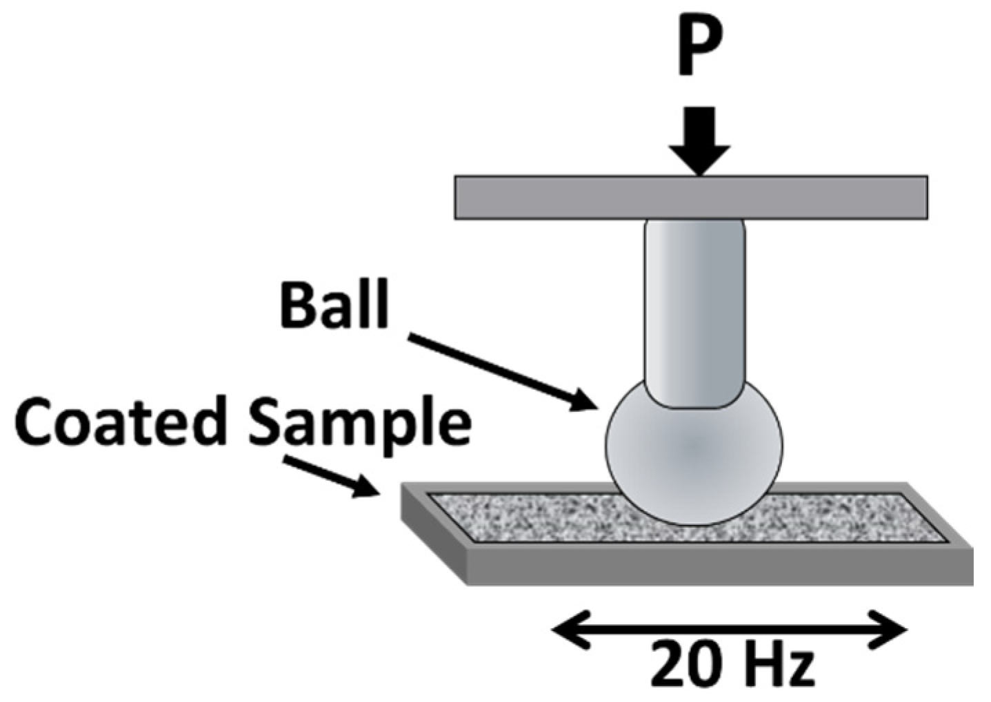
An inhouse Fretting Wear rig was used to measure the friction coefficient in pure sliding conditions (Figure 1). The variable sample was the AISI52100 through-hardened steel plate which was either uncoated or coated with the three different types of conversion layers. The lay of the surface topography is disposed perpendicularly to the movement of the ball. Table 1 specifies the test conditions, each test being repeated at least two times. The amplitude of the reciprocal displacement is smaller than the semi-contact width which corresponds to fretting corrosion.
2.2.2. Ball-on-Disk and Roller-on-Disk Rolling/Sliding Tests
The friction performance in rolling/sliding conditions was evaluated using a WAM test rig (Wedeven Associates Machine, Inc., Edgmont, PA, USA) under conditions relevant to cylindrical and tapered rolling element bearings. The WAM rig was used in two different configurations, one simulating a bearing raceway contact, the other simulating a bearing roller-end to flange contact.
Ball-on-disk test, with a 20.64 mm diameter ball and a disk independently driven (Figure 2), giving the possibility to obtain various slide-to-roll ratios. The ball and disk rotation speeds, load, and test temperature are computer-controlled and can be varied according to a planned test sequence. The traction force between the ball and the disk is continuously measured. The test sequence comprises Stribeck curves and Traction curves performed before and after a duration step of 70 h.
Roller-on-disk test, similar to the previous one, but where the ball is replaced by a tapered roller (Figure 3). In this way, it is possible to simulate the flange contact of a roller against a bearing ring with a maximum contact pressure of 270 MPa. The roller position on the disk is chosen in a way that the outer diameter of the roller rotates at the same speed of the disk at that position. In this way, therefore, the slide-to-roll ratio is geometrically defined by the angle α of the roller-end motor. This contact configuration adds spinning motion to the rolling/sliding contact (as in application flange contacts). This angle is fixed in order to have the running track in the center of the usable roller end face. The test sequence comprises Stribeck curves performed before and after a duration step of 4.5 h. And, similarly to the ball-on-disk setup, the traction force between the ball and the disk is continuously measured.
The test conditions for both configurations are specified in Table 2. The ISO VG 32 lubricant was continuously supplied onto the rotating disk, ensuring fully flooded conditions. The rotation speed was adjusted to run in mixed lubrication, with the lubrication parameter λ of 0.3 considering the initial roughness of the disk prior to coating (λ is the ratio of central film thickness over the root mean square roughness Rq).
The test samples, notably the coated disks, have surface topographies representative of inner rings of railway wheel-end bearings. The ball and the roller are both made of AISI 52100 through-hardened steel. The balls are finished to an average root mean square roughness Rq = 50 ± 10 nm. The end-face tapered rollers are cross-honed to an average roughness of Rq = 100 ± 15 nm. The steel disks, also made of AISI 52100 through-hardened steel, are circularly honed to an average root mean roughness Rq = 230 ± 15 nm, prior to coating. They are circularly honed, in order to have the lay of topography in the over-rolling direction, like in a bearing ring. All WAM tests were repeated at least two times.
2.2.3. Bearing Friction Test Rig
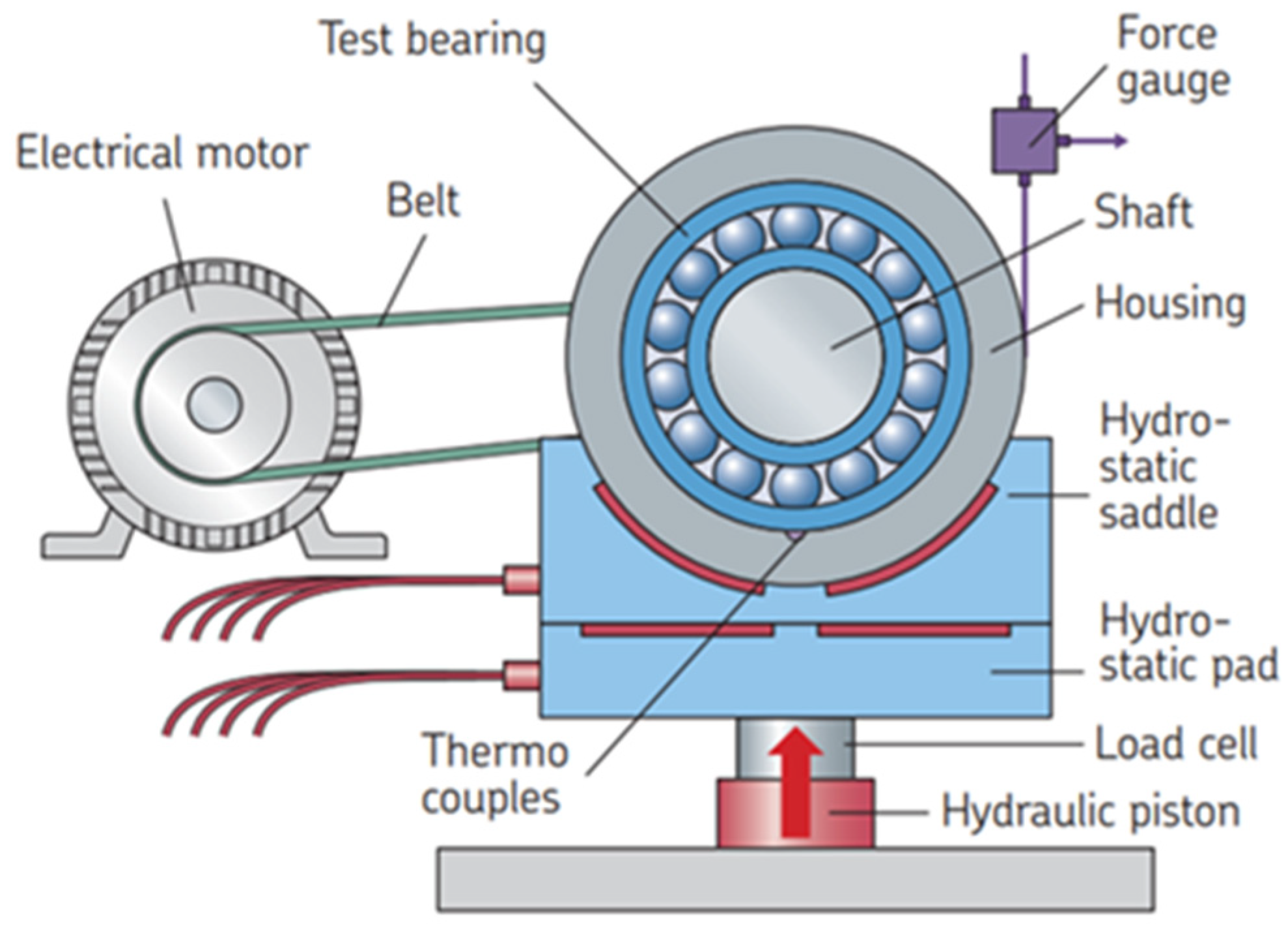
An inhouse test rig designed specifically to measure bearing friction torque under various speed and load conditions (Figure 4) was used to compare the different conversion layers in conditions as close as possible to typical intercity train wheel-end bearing units. Because wheel-end bearing units are typically double-row units, the tests were performed with a double CRB (cylindrical rolling bearing) setup (NU2207 ECP/C3 and NJ 2207 ECP/C3). Cylindrical bearings were selected instead of tapered bearings to facilitate disassembly/reassembly of the roller sets to coat the inner and outer rings. The roller sets were kept with original rings to maintain C3 clearance. Prior to testing, each bearing was filled with 2.5 g of a typical railway grease ensuring the same initial grease distribution.
The test rig is controlled and can run test profiles varying radial and axial loads, speeds, and temperatures. The overall test conditions for this study are specified in Table 3. In general, the test profiles are used by varying either the rotation speed (to vary the film thickness) or the axial load (to emphasize the flange contact contribution). The radial load has been set to reach contact pressures of 1.3 GPa on the inner ring and 1 GPa on the outer ring. The axial load for the speed cycles was set to reach 200 MPa on the flange contact. The speed cycle (Table 4) has been designed to represent typical linear speeds obtained in intercity railway wheel-end units and also to minimize the effect of grease movements on the measured torque. The axial load cycle (Table 5) has been designed to stress the flange contribution yet staying below the maximum recommended axial to radial load ratio.
The test rig, test setups with double CRB and test profiles have been used extensively in the past decade to screen design parameters affecting bearing torque [31]. After 10 h running-in, each speed or axial load step of 1 h is divided into 30 min clockwise and 30 min counterclockwise rotation at the given speed, and the torque is averaged over the last 20 min of each. This enables correction of any offset in the force gauge, leading to a low standard deviation. Each cycle is repeated at least 6 times after the running-in and each test is repeated on at least 2 bearing sets. In this test campaign, the inner and outer rings were kept uncoated, or coated with either TBO, MnPh, or ZnCaPh. The rollers were kept uncoated.
2.3. Morphological Characterizations
Surface morphology studies were carried out by a scanning electron microscope (SEM) FEI—TENEO operating at 10 kV. Surface roughness Ra (average roughness), and Rq (root mean square roughness) and wear tracks depths were characterized by a white light interferometer (GT Contour, Brucker, Elk Grove Village, IL, USA).
Nanoindentation experiments were performed with a diamond Berkovich indenter with a tip radius of approximately 150 nm. The employed equipment was a TI Premier Hysitron from Bruker with a vertical displacement resolution of 0.01 nm, a force resolution of 0.075 μN, an internal noise uncertainty of 0.2 nm, and thermal drift at room temperature below 0.05 nm/min. In all experiments, the loading and unloading times to/from maximum load were 5 s and the holding period, in which the load was kept constant to eliminate creep effects, was 2 s. All indentations were load controlled, so the maximum load was identical for all measurements. Calculation of hardness and reduced elastic modulus for each nanoindentation measurement was conducted according to the method of Oliver and Phar [32].
3. Results
3.1. Morphology and Mechanical Properties
Figure 5 displays SEM plan-views with the morphology of the three conversion layers. The TBO coating (Figure 5a) shows the presence of voids and cracks. The void formation has been attributed to the nature of the oxide conversion [33], while the cracks have been linked to surface stress relief cracks because the oxide layer has a different thermal expansion coefficient compared to the steel substrate [34]. The MnPh coating (Figure 5b) exhibits a polycrystalline microstructure with prismatic-shaped crystals of about 5–10 µm. The ZnCaPh coating has a compact microstructure with a uniform distribution of grains (Figure 5c), thanks to the incorporation of Ca during the phosphating process. Bhar et al. [7] have shown that the incorporation of Ca changes the microstructure of the zinc phosphate coatings from phosphophylite-hopeite to schlozite-hopeite with an increase in density and a reduction in grain size from 25 to 4 µm.
Different nanoindentation tests were carried out on uncoated and coated samples. In the case of uncoated steel, or measurements inside the wear track of WAM samples, 16 indents at a maximum applied load Lmax of 10 mN were performed, and the mean value and error were calculated.
In the case of coatings, the calculation of coating hardness and elastic modulus was performed according to the ISO 14577 nanoindentation standard [35]. At least 16 indentations were produced in the coating at penetration depths in the range 5%–10% of the total coating thickness to avoid the influence of the substrate [36], and a mean value and error were calculated.
Table 6 shows the hardness HIT and the reduced elastic modulus Er of the three conversion coatings measured by nanoindentation outside and inside the tracks on the WAM disks. In general, a high dispersion (>10%) in the values is observed. For the TBO, the dispersion probably originated from the presence of voids and cracks in the coating. The results are in line with measurements published in the literature [15]. For the MnPh and ZnCaPh, the dispersion originates from their polycrystalline, granular microstructure [36]. Furthermore, the presence of an initial roughness of Rq = 250 nm prior to coating (on uncoated and coated samples) also contributes to the increase in the dispersion of the values [36].
3.2. Reciprocating Sliding Tests
Figure 6 compares the friction coefficient behavior for all coatings at the end of the reciprocating tests where, after a short run-in period, all coatings display a constant friction. Table 7 details various observations made on the wear scars observed after the test. We have observed that TBO and MnPh coatings have scars of ~2 µm depth, ZnCaPh scar is slightly shallower (about 1.8 µm), while the steel layer presents just some smoothening of the initial roughness peaks. From these scar depth values, we conclude that only TBO (which has a thickness of ~1 µm) is gone before the end of the test, while the other two coatings still are found in the wear track. Furthermore, comparing roughness values outside the wear track, we notice that the roughness value outside the TBO wear track presents the lowest value among all measured samples. The result indicates that, under such fretting wear conditions, the friction coefficient is lower for conversion coatings, likely due to the eased smoothening of the initial roughness peak. The lowest friction coefficient is obtained with the TBO-coated plates, even if the coating has already been worn off before the end of the test.
3.3. Rolling/Sliding Tests
During the WAM ball-on-disk and roller-on-disk tests, the traction force is continuously measured. Figure 7 and Figure 8 present the evolution of the traction coefficient for the raceway (ball-on-disk) and flange (roller-on-disk), respectively. For the sake of simplicity, here are presented the average traction coefficients of the first and last phase of the duration steps running in mixed lubrication (λ = 0.3), but the same trends are observed looking into the Traction and Stribeck curve steps of the test profiles. Figure 9 illustrates the typical evolution of friction during the rolling/sliding tests, here for the roller-on-disk configuration. The evolution corresponds to the evolution of the start and end friction bars illustrated in Figure 8. It further explains why the standard deviation bars are typically tighter at the end of the tests than at the start, in Figure 7 and Figure 8. Table 8 summarizes the average roughness of the disks outside and inside the tracks of both the ball-on-disk and roller-on-disk tests. Prior to coating, all the steel disks had a roughness of 230 ± 15 nm.
In the raceway and flange contact conditions, we can observe that, while MnPh and ZnCaPh present significant drops in friction from start to end of the duration step compared to the steel variant (related to running-in of the conversion layers), TBO presents the lowest friction already from the start (Figure 7 and Figure 8). The friction coefficients measured are comparable to other ball-on-disk tests reported in the literature comparing steel–steel and TBO–steel contacts [15]. One can notice that, at the end of the raceway configuration, MnPh–steel has only a slightly higher value than TBO–steel. However, some of the results suggest that MnPh would provide fewer benefits than TBO on application level: (1) In the raceway configuration, the friction benefit for MnPh only comes at the end of the test (similar level to steel–steel at start, Figure 7), while it comes already from the start with TBO; (2) In the flange configuration, the friction coefficient of TBO–steel is much lower than MnPh–steel (Figure 8). The benefits in friction can be compared to roughness inside the running track after the tests (Table 8), which is significantly lower for the TBO disk both in the raceway and flange configuration.
Because conversion layers are typically softer than through-hardened steel, friction benefits are typically obtained when applying the coating to the rougher countersurface to easy running-in and smoothening of the rougher asperities [12,15]. Conversely, if the conversion layer was applied to the smoother surface, the harder and rougher surface would then wear off and damage the conversion layer, with negative impact on performance. In an attempt to consolidate the above understanding, additional variants have been added in the WAM experiments to test the TBO and MnPh in two ways: uncoated steel balls against the coated disks, and the coated balls against coated disks. The results confirm that, under our test conditions, the lower friction for TBO and MnPh coatings is observed when only the disk, rougher than the ball, is coated (Figure 7).
Focusing on the TBO–steel, which shows the lowest friction coefficients, one can notice that the TBO–steel in the flange contact configuration leads to much lower friction coefficients than friction coefficients typically observed in ball-on-disk tests (usually ranging from 0.04 to 0.10). The same could be observed for MnPh–steel but to a lesser extent. This could be explained by the increased smoothening of the flange contact compared to the raceway contact (Table 8). An additional explanation is provided in the discussions.
3.4. Bearing Friction Tests
The average torque measured at different rotational speeds on the double CRB setup is presented in Figure 10 for the tests with uncoated steel rings and with the TBO, MnPh, and ZnCaPh rings. The average torque is normalized to the one measured in the case of the uncoated rings at 3100 rpm and 250 N axial load. After the speed cycle tests, the roughness of the raceway and flange on the NJ2207 inner rings have been measured by interferometry (Table 9). The roughness measured is compared to that of the average roughness of the new inner ring raceway.
Figure 10 shows that the TBO rings consistently lead to the lowest torque, which correlates with observations made on the ball-on-disk. Roughness measurements suggest that the lower torque may come from the running-in and smoothened surface topography on the inner ring raceway and flange (Table 9). This may explain why the TBO benefits are somewhat reduced at higher speeds, where the film thickness separating the surfaces is higher.
In Figure 10, the bearing friction gains obtained by applying TBO on the rings are greater at 250 N axial load than at 100 N axial load (both at 1800 rpm). It can be explained by the fact that the largest contribution to torque in a radially and axially loaded CRB will be the sliding resistance from the flange contacts. In that respect, the uncoated steel rings and the TBO rings have been tested in the axial load cycle where the radial load is kept constant but where the axial load is increased to emphasize the friction contribution. The axial load cycle tests were performed with the reference grease and with another low-friction grease (Grease2) to compare the effect of applying TBO on the rings with the effect of a low-friction grease (Figure 11). It can be observed that: on the one hand, for uncoated steel rings, bearing torque linearly increases when increasing the axial load, hence the flange contact contribution; on the other hand, for TBO rings, bearing torque barely increases with increase in axial load. In Figure 11, compared to the steel variant, at 0.2 kN axial load, TBO shows 50% less bearing friction with the first grease, while at high axial load of 0.7 and 1.0 kN, TBO shows up to 75% less bearing friction with the first grease. This observation correlates with the fact that higher friction gains have been measured on the roller-on-disk flange configuration than on the ball-on-disk raceway configuration. Figure 11 also illustrates that, from a friction perspective, the benefits of applying TBO are greater than applying a low-friction grease under the tested conditions.
It can be expected that, with excessive axial load, the TBO could have the opposite effect by accelerating flange wear. To make sure that this did not happen during the axial load cycles with maximum axial load of 1000 N, Figure 12 and Figure 13 display the evolution of the bearing torque in time, as the axial load cycle from 200 to 1000 N is repeated (16 times in total), which is behind the averages plotted in Figure 11. It can be observed that the bearing torque is not increasing in time, suggesting that the flange contact is not being worn. It can also be seen that the TBO rings not only provide a lower bearing torque but also a more stable one, notably at the higher axial load configuration. MnPh and ZnCaPh rings show less stable bearing torque (similar to uncoated rings), as also seen in the standard deviation bars of Figure 10.
4. Discussion
4.1. Conversion Layers on the Rougher Surface to Facilitate Running-In
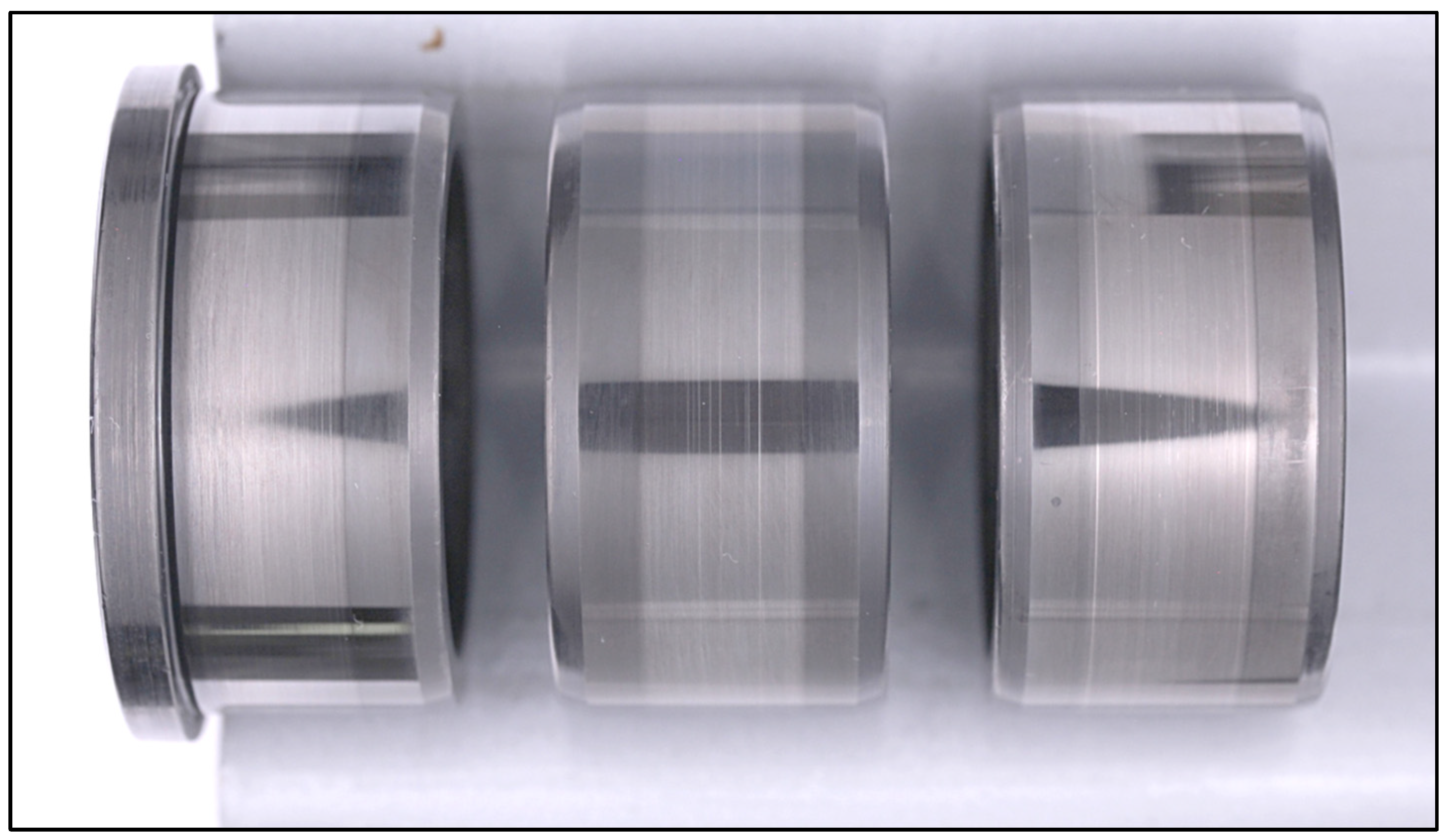
The conversion layers tested (TBO, MnPh, and ZnCaPh) are softer than the baseline through-hardened bearing steel, as confirmed by the nanoindentation measurements (Table 6). Because of previous observations from ball-on-disk with uncoated, TBO [12,15], and MnPh samples, a hypothesis has been made that the soft conversion should be applied to the rougher surface to facilitate running-in: disks on the ball-on-disk and roller-on-disk tests and rings on the double CRB tests. The WAM results, the Bearing Friction results, and the respective roughness measurements in and outside the tracks confirm this hypothesis. Figure 14 illustrates the typical visual appearance of the running-in wear of the conversion layers, in this specific case the one observed on the inner rings with TBO after the bearing friction tests.
More specifically, it can be observed that the difference in roughness prior to coating and after testing in the WAM and in the Bearing Friction tests, influences how much friction reduction can be obtained by applying the conversion layer. In the WAM tests, the initial steel disk roughness was 230 ± 15 nm, and the surface initially became much rougher when applying MnPh and ZnCaPh due to the crystalline structure. At the end of the test, all the conversion layers show lower roughness inside the running track (Table 8), notably for the flange contact where the biggest friction gains were observed (Figure 8). In that respect, the ZnCaPh WAM tests stand out because a lower friction than steel was measured as well as lower roughness inside the track, but the lower nanoindentation hardness and elastic modulus values suggest that there are ZnCaPh residuals in the track (Table 6), apparently flattened out.
In the Bearing Friction test, it can be observed that the friction gains, by applying MnPh or ZnCaPh coatings on the rings, are less than on the WAM tests, and in some cases MnPh and ZnCaPh even lead to higher friction than uncoated bearings (Figure 10). This can be explained by the fact that the initial roughness of the bearing inner and outer ring, prior to coating, was substantially lower than with the WAM disk. Therefore, since MnPh and ZnCaPh initially introduce a much higher roughness, the roughness in the track after testing remains higher than the ones of uncoated rings (Table 9): all are in the range of 140% more than the initial steel roughness. For the TBO, the bearing torque is always lower since the TBO does not initially roughen the surfaces and typically leads to surface run-in tracks smoother than the ones on uncoated rings (typically 50% smoother, Table 9). This explains why TBO has provided the lowest friction in all the test configurations. All those results underline the importance of applying conversion layers on the rougher counterparts for friction performance and that benefits are likely to be enhanced in the case of rougher initial surfaces.
Finally, because the benefits of applying a conversion layer for friction reduction come from enhanced smoothening during running-in wear, extra tests were performed to verify that TBO (but also MnPh and ZnCaPh) would not come with a compromise on reliability by increasing the risk of surface distress, mild wear, and smearing, but also by increasing grease ageing due to iron oxide or phosphate particles in the grease. The results confirm that the benefits obtained by easing the running-in also come with enhanced performance in terms of surface distress and wear when the TBO is applied on the rougher surface, as also reported by [15]. In application, depending on the operating conditions, the TBO may appear visually black even after a long duration, and may appear brighter and polished away within the rolling element contact areas. Even if, visually, it appears worn off, a thin layer remains with a higher oxygen content and smoothened surface. It is worth emphasizing that, outside the rolling contact areas, the TBO will bring other benefits like moderate protection against corrosion, increased lubricant wettability, hydrogen barrier, etc., [2]. In general, outside the rolling contact areas, all conversion layers are expected to remain, providing the expected benefits such as protection against corrosion.
4.2. The Influence of Conversion Layers on the Flange Contacts
Both the WAM rolling/sliding tests and the bearing friction tests showed that TBO had optimum friction reduction potential. Under the tested conditions, applying TBO on the disk reduces the friction coefficient from 0.08 to 0.06 in the raceway configuration (Figure 7) and from 0.09 to 0.02 in the flange contact configuration (Figure 8), compared to uncoated disks. In the bearing tests with double CRB, applying TBO on the inner and outer rings reduced up to 75% the bearing torque (compared to uncoated rings) when applying a five times’ higher axial load (hence increasing the flange contact contribution). Both results suggest that a significant part of the friction benefits of applying TBO in a bearing come from the flange contacts.
One hypothesis to explain that phenomenon is the higher SRR in the flange contact, suggesting that running-in wear would be more important in the flanges than in the raceways. However, the roughness measurements (Table 8 and Table 9) do not fully support this idea.
The other hypothesis is that the contribution of having a conversion layer softer than steel to facilitate running-in and smoothening of the asperities will increase with lower contact pressures. Indeed, with lower contact pressures on the flanges (0.1 to 0.3 GPa), the asperities have less tendency to smoothen or wear off than at higher contact pressures of raceway contacts (1 to 1.5 GPa). This possibility could be explained from the plasticity-based dry friction theory: at lower contact pressures for the flanges, softening (e.g., reducing the yield strength) of asperities could change the dominant deformation mode from elastic to plastic that, in its turn, will reduce the friction. At higher contact pressures, this effect will be less prominent because the asperity deformation mode will be plastic even without TBO. This has previously been explained for dry contacts [37], and is likely also true for lubricated contacts running in mixed or boundary lubrication regimes.
5. Conclusions
This is the first research available in the literature where the friction behavior of three different conversion layers used in rolling bearing applications has been compared under the same tribological conditions. All our results indicate that, when compared to uncoated rings, the TBO coating promotes the greatest friction reduction potential for railway wheel-end bearing units. In addition:
TBO, MnPh, and ZnCaPh microstructures have been characterized by SEM and correlated to nanoindentation hardness and elastic modulus measured in both, outside and inside the rolling/sliding tracks.
Roughness analysis of all the test samples indicates that the friction reduction originated from a facilitated running-in and smoothening of the rings’ raceways when applying the soft TBO conversion layer on the rougher surfaces, which are typically the rings in a bearing.
Roughness analysis also demonstrates that the benefits of applying TBO are often more pronounced than for MnPh and ZnCaPh due to the lower initial TBO roughness after coating (due to its lower thickness and non-crystalline microstructure).
The tribological results obtained in various contact conditions demonstrate that a significant part of the benefits of applying TBO to reduce bearing friction come from the flange contacts, where contact pressures do not facilitate running-in (compared to raceway contact pressures).
It should be finally noted that all the interpretations in this study are made based on mechanical considerations and do not include potential interaction with the lubricant.
Author Contributions
Conceptualization: E.B., A.R. and V.B.; methodology: E.B. and A.R.; validation: E.B., A.R., R.M. and D.N.; formal analysis: A.R.; investigation: E.B., A.R., R.M. and D.N.; project administration: A.R.; resources: E.B. and A.R.; data curation: A.R.; writing—original draft preparation: E.B. and A.R.; writing—review & editing: E.B., A.R. and V.B. All authors have read and agreed to the published version of the manuscript.
Funding
This research received no external funding.
Institutional Review Board Statement
Not applicable.
Informed Consent Statement
Not applicable.
Data Availability Statement
The data that support the findings of this study are available from the corresponding author upon reasonable request.
Acknowledgments
The authors acknowledge Robertina Filocomo for performing the reciprocating-sliding tests, and Dipl.-Ing. Thilo von Schleinitz from SKF GmbH (Germany) for enlightening discussions about Tribological Black Oxide coatings.
Conflicts of Interest
The authors declare no conflict of interest.
References
- Craven, N. “UIC Low Carbon Rail Challenge—Technical Report,” International Unions of Railway. Available online: https://uic.org/IMG/pdf/low_carbon_rail_challenge_technical_report.pdf (accessed on 6 March 2023).
- SKF. “SKF Coatings Catalogue,” SKF, [Online]. Available online: https://www.skf.com/binaries/pub12/Images/0901d19680a4e17f-18781-EN---Coating-catalogue_for-digital-use-only_noprint_tcm_12-549101.pdf (accessed on 6 March 2023).
- Broitman, E. Coatings to Improve Bearing Performance. Evolution 2022, 1–7. Available online: https://evolution.skf.com/coatings-to-improve-bearing-performance/ (accessed on 6 March 2023).
- Gregory, J.C. Chemical coatings of metals to resist scuffing and wear. Tribol. Int. 1978, 11, 105–112. [Google Scholar] [CrossRef]
- George, M.A. Factors Influencing Friction of Phosphate Coatings; Springfield Armory: Geneseo, IL, USA, 1964. [Google Scholar]
- Saffarzade, P.; Amadeh, A.A.; Agahi, N. Study of tribological and friction behavior of magnesium phosphate coating and comparison with traditional zinc phosphate coating under dry and lubricated conditions. Tribol. Int. 2019, 144, 106122. [Google Scholar] [CrossRef]
- Bhar, G.N.; Debnath, N.C.; Roy, S. Effects of Calcium Ions on the Morphology and Corrosion Resistance of Zinc-Phosphated Steel. Surf. Coat. Technol. 1988, 35, 171–179. [Google Scholar] [CrossRef]
- von Schleinitz, T.; Nentwig, K.; Bruckhaus, C.; Kachler, W. Brünierung: Die alte newe Hochleistungsschicht. Galvanotechnik 2018, 5, 889–894. [Google Scholar]
- Deutsches Institut fur Normung. DIN 50938—Black Oxide Coatings on Ferreous Metal Components—Requeriments and Test Methods; Deutsches Institut fur Normung e.V.: Berlin, Germany, 2018. [Google Scholar]
- ISO 11408; Chemical Conversion Coatings—Black Oxide Coating on Iron and Steel—Specification and Test Methods. International Organization for Standardization: Geneva, Switzerland, 1999.
- Broitman, E. Black Oxide and Carbon-Based Coatings for Roller Bearing Applications. In Proceedings of the 46th International Conference on Metallurgical Coatings and Thin Films, San Diego, CA, USA, 19–24 May 2019. [Google Scholar]
- Brizmer, V.; Stadler, K.; van Drogen, M.; Han, B.; Matta, C.; Piras, E. The Tribological Performance of Black Oxide Coating in Rolling/Sliding Contacts. Tribol. Trans. 2017, 60, 557–574. [Google Scholar] [CrossRef]
- Stadler, K. How black oxide coating can make an impact on cutting O&M costs for wind turbines. Evolution 2013, 4. Available online: https://evolution.skf.com/how-black-oxide-coated-bearings-can-make-an-impact-on-cutting-om-costs-for-wind-turbines/ (accessed on 6 March 2023).
- Dvorak, P. SKF Black Oxide Bearings Add Surface Layer of Protection to Promote Higher Reliability and Performance for Wind Turbines. Windpower Engineering and Development, vol. June. 2014. Available online: https://www.windpowerengineering.com/skf-black-oxide-bearings-add-surface-layer-protection-promote-higher-reliability-performance-wind-turbines/ (accessed on 6 March 2023).
- Ueda, M.; Spikes, H.; Kadiric, A. Influence of Black Oxide Coating on Micropitting and ZDDP Tribofilm Formation. Tribol. Trans. 2022, 65, 242–259. [Google Scholar] [CrossRef]
- Riggs, M.R.; Murthy, N.K.; Berkebile, S.P. ARL-TR-7815: Evaluation for Loss of Lubrication Performance of Black Oxide, Superfinished, and As-Ground Surfaces for Use in Rotorcraft Transmissions; US Army Research Laboratory, Aberdeen Proving Ground: Harford, MD, USA, 2016. [Google Scholar]
- Ernens, D.; de Rooij, M.B.; Pasaribu, H.R.; van Riet, E.J.; van Haaften, W.M.; Schipper, D.J. Mechanical characterization and single asperity scratch behaviour of dry zinc and manganese phosphate coatings. Tribol. Int. 2018, 118, 474–483. [Google Scholar] [CrossRef]
- Ozkan, D.; Kaleli, H.; Yuksek, L. Quantitative comparison of tribological performance of chromium- and zinc-phosphate-coated piston rings in tribotest rig. Proc. IMechE Part J J. Eng. Tribol. 2017, 231, 75–92. [Google Scholar] [CrossRef]
- Farias, M.C.M.; Santos, C.A.L.; Panossian, Z.; Sinatora, A. Friction behavior of lubricated zinc phosphate coatings. Wear 2009, 266, 873–877. [Google Scholar] [CrossRef]
- Hao, L.; Chen, Y.; Li, G.; Zhang, M.; Wu, Y.; Liu, R.; Chen, G. Study on the Friction Characteristics and Fatigue Life of Manganese Phosphate Coating Bearings. Lubricants 2023, 11, 99. [Google Scholar] [CrossRef]
- Leidich, E.; Maiwald, A.; Vidner, J. Extended studies on fretting wear criterion for coated systems with complete contact based on accumulated specific friction energy. WIT Trans. Eng. Sci. 2012, 76, 163–174. [Google Scholar]
- Kozlowski, A.; Czechowski, W. Wear resistance of manganese phosphate coatings. Electrodepos. Surf. Treat. 1975, 3, 55–63. [Google Scholar] [CrossRef]
- Hager, C.H.; Evans, R.D. Friction and wear properties of black oxide surfaces in rolling/sliding contacts. Wear 2015, 338–339, 221–231. [Google Scholar] [CrossRef]
- Zang, L.; Zhong, Q.; Chen, Y.; Hou, W.; Zhao, B.; Wu, Y. Effect of coating thickness on tribological properties of manganese phosphate conversion coating in different motion conditions. Tribol. Int. 2022, 176, 107894. [Google Scholar] [CrossRef]
- Tamura, Y.; Kobayashi, K.; Aratani, K.; Tanaka, S.; Kikuchi, M.; Masuko, M.; Ohtake, N. Influence of Wear Surface Morphology and Phosphorus-Containing Tribofilm on Crack Initiation of Manganese Phosphate Coated Steel under Rolling–Sliding Contact. Tribol. Online 2020, 15, 154–169. [Google Scholar] [CrossRef]
- Mendibil-Zaballa, E.; Sánchez-Galíndez, J.A.; Saenz-de-Ugarte-Sevilla, P.; Pombo-Rodillad, I.; Fernandez-Sisóne, A. Tribo-mechanical Characterisation of Wear Behaviour for Manufacturing of Wind Turbine Gearbox Structural Parts. Procedia Eng. 2015, 132, 918–925. [Google Scholar] [CrossRef]
- Waterhouse, R.B. The Formation, Structure and Wear Properties of Cerain Non-metallic Coatings on Metals. Wear 1965, 8, 421–447. [Google Scholar] [CrossRef]
- Waterhouse, R.B.; Allery, M. The effect of non-metallic coatings on the fretting corrosion of mild steel. Wear 1965, 8, 112–120. [Google Scholar] [CrossRef]
- SKF. Railway Technical Handbook—Volume 1; SKF Group: Goterborg, Sweden, 2011. [Google Scholar]
- ISO 9717; Metallic and Other Inorganic Coatings—Phosphate Conversion Coating of Metals. International Organization for Standardization: Geneva, Switzerland, 2017.
- De Vries, L.; Bin Yusof, N.; Van Eijk, M.C.P. Grease Selection for Wheelset Bearings in Passenger Trains. In Proceedings of the XIX International Wheelset Conference—IWC 2019, Venice, Italy, 16–20 June 2019. [Google Scholar]
- Oliver, W.; Pharr, G. An improved technique for determining hardness and elastic modulus using load and displacement sensing indentation experiments. J. Mater. Res. 1992, 7, 1564–1583. [Google Scholar] [CrossRef]
- Ooi, S.W.; Yan, P.; Vegter, R.H. Black oxide coating and its effectiveness on prevention of hydrogen uptake. Mater. Sci. Technol. 2019, 35, 12–25. [Google Scholar] [CrossRef]
- Kooi, B.J.; Somers, M.A.J.; Jutte, R.H.; Mittemeijer, E.J. On the oxidation ofα-Fe andε-Fe2 N1−z II. Residual strains and blisters in the oxide layer. Oxid. Met. 1997, 48, 111–128. [Google Scholar] [CrossRef]
- ISO-14577-1; Metallic Materials—Instrumented Indentation Test for Hardness and Materials Parameters—Part 1: Test Method. International Organization for Standardization: Geneve, Switzerland, 2015.
- Broitman, E. Indentation Hardness Measurements at Macro-, Micro-, and Nanoscale: A Critical Overview. Tribol. Lett. 2017, 65, 23. [Google Scholar] [CrossRef]
- Brizmer, V.; Kligerman, Y.; Etsion, I. Elastic-plastic spherical contact under combined normal and tangential load in full stick. Tribol. Lett. 2007, 25, 61–70. [Google Scholar] [CrossRef]
Figure 1.
Schematics of fretting test.

Figure 2.
Ball-on-disk configuration schematics of the WAM rig, where the ball speed Ub and the disk speed Ud can be independently regulated.
Figure 2.
Ball-on-disk configuration schematics of the WAM rig, where the ball speed Ub and the disk speed Ud can be independently regulated.

Figure 3.
Roller-on-disk configuration schematics of the WAM rig, where the roller speed Ur and the disk speed Ud can be independently regulated.
Figure 3.
Roller-on-disk configuration schematics of the WAM rig, where the roller speed Ur and the disk speed Ud can be independently regulated.

Figure 4.
Schematic of the bearing friction test rig where the test bearing housing is isolated on hydrostatic bearings both in the radial and axial direction and where the force gauge will measure torque in clockwise and counterclockwise rotation (adapted from [31]).
Figure 4.
Schematic of the bearing friction test rig where the test bearing housing is isolated on hydrostatic bearings both in the radial and axial direction and where the force gauge will measure torque in clockwise and counterclockwise rotation (adapted from [31]).

Figure 5.
SEM microscopy of the respective conversion layers: (a) Tribological Black Oxide; (b) Manganese Phosphate; (c) Zinc Calcium Phosphate. Note that magnification in (b) is half the magnification in (a,c).
Figure 5.
SEM microscopy of the respective conversion layers: (a) Tribological Black Oxide; (b) Manganese Phosphate; (c) Zinc Calcium Phosphate. Note that magnification in (b) is half the magnification in (a,c).


Figure 6.
Average friction coefficient measured in the last 22,000 cycles of the 72,000 cycles of the reciprocating sliding test for the different versions. Average standard deviation of 0.005.
Figure 6.
Average friction coefficient measured in the last 22,000 cycles of the 72,000 cycles of the reciprocating sliding test for the different versions. Average standard deviation of 0.005.

Figure 7.
WAM Raceway test results: start (end) value is the average traction coefficient during the first (last) hour of the 70 h duration step; first material refers to the disk (rougher), second to the ball (smoother).
Figure 7.
WAM Raceway test results: start (end) value is the average traction coefficient during the first (last) hour of the 70 h duration step; first material refers to the disk (rougher), second to the ball (smoother).

Figure 8.
WAM Flange test results: start (end) value is an average of the first (last) 30 min of the 4 h duration step; first material refers to the disk (rougher), second to the ball (smoother). Note that the second test was not performed for the MnPh–MnPh variant.
Figure 8.
WAM Flange test results: start (end) value is an average of the first (last) 30 min of the 4 h duration step; first material refers to the disk (rougher), second to the ball (smoother). Note that the second test was not performed for the MnPh–MnPh variant.

Figure 9.
WAM Flange test friction curves from where Figure 8 average traction coefficients are extracted.
Figure 9.
WAM Flange test friction curves from where Figure 8 average traction coefficients are extracted.

Figure 10.
Average bearing torque depending on the rotation speed for the different variants: each bar represents the average of the torque for a given speed over the number of repeats R of the speed cycle; each deviation bar corresponds to the standard deviation over the number of repeats R.
Figure 10.
Average bearing torque depending on the rotation speed for the different variants: each bar represents the average of the torque for a given speed over the number of repeats R of the speed cycle; each deviation bar corresponds to the standard deviation over the number of repeats R.

Figure 11.
Average bearing torque depending on the axial load applied on the test head for steel and TBO variants: each bar represents the average of the torque for a given speed over the number of repeats R of the speed cycle, with an average standard deviation of 14%.
Figure 11.
Average bearing torque depending on the axial load applied on the test head for steel and TBO variants: each bar represents the average of the torque for a given speed over the number of repeats R of the speed cycle, with an average standard deviation of 14%.

Figure 12.
Evolution of torque for steel bearing in time over the 16 repeats for the respective axial loads (torque is normalized as in Figure 11).
Figure 12.
Evolution of torque for steel bearing in time over the 16 repeats for the respective axial loads (torque is normalized as in Figure 11).

Figure 13.
Evolution of torque for TBO bearing in time over the 16 repeats for the respective axial loads (torque is normalized as in Figure 11).
Figure 13.
Evolution of torque for TBO bearing in time over the 16 repeats for the respective axial loads (torque is normalized as in Figure 11).

Figure 14.
Typical inner ring appearance after the Bearing Friction tests for the TBO tests: the TBO layer is partially worn off by running-in wear in the track corresponding to the roller width.
Figure 14.
Typical inner ring appearance after the Bearing Friction tests for the TBO tests: the TBO layer is partially worn off by running-in wear in the track corresponding to the roller width.


Table 1.
Fretting Wear Rig test conditions.
| Parameter | Values |
|---|---|
| Ball Diameter | 12.7 mm |
| Load | 15.3 N |
| Initial Hertzian Contact Pressure | 1 GPa |
| Circular Contact Radius (a) | 85 µm |
| Reciprocal stroke | 100 µm |
| Frequency | 20 Hz |
| Temperature | Room Temperature |
| Number of Cycles | 72,000 |
| Total Distance | 7.2 m |
| Test Duration | 1 h |
| Lubricant | Railway grease (PAO base oil ISO VG100) |
Table 2.
Test conditions for the ball-on-disk and roller-on-disk WAM tests.
| Setup | Ball-on-Disk | Roller-on-Disk |
|---|---|---|
| Initial Contact Pressure PH | 1.3 GPa | 0.27 GPa |
| Entrainment Speed | 0.5 m/s | 0.3 m/s |
| SRR (slide-to-rolling ratio) | 5% (except traction curves) | 9.6% (with spinning component) |
| Lubricant | Mineral oil of 32 cSt at 40 °C with no EP/AW additives | |
| Temperature | 60 °C | |
| Lubrication Parameter λ | λ = 0.3 | |
| Test Sequence | Traction; Stribeck; Duration 70 h; Traction; Stribeck | Stribeck; Duration 4.5 h; Stribeck |
Table 3.
Overview of the test conditions on the Bearing Friction test rig with a double CRB setup and either speed cycles or axial load cycles.
Table 3.
Overview of the test conditions on the Bearing Friction test rig with a double CRB setup and either speed cycles or axial load cycles.
| Bearings | NU2207 + NJ2207 |
| Radial load (N) | 7000 |
| Axial load (N) | Speed cycles: 250 Axial load cycles: from 200 to 1000 |
| Speed (rpm) | Speed cycles: from 300 to 4500 Axial load cycles: 1800 Direction: 0.5 h CW and 0.5 h CCW |
| Lubrication | Railway grease (PAO base oil ISO VG100) |
| Temperature | 60 °C |
| Repeats | Cycles repeated mini 6 times and up to 24 times |
| Running-in/Grease churning | 10 h at 3100 rpm and 250 N axial load |
Table 4.
Bearing Friction speed cycle repeated minimum 9 times.
| Step | Duration (h) | Axial Load (N) | Speed (rpm) |
|---|---|---|---|
| Run-in | 10 | 250 | 3100 |
| Step 1 | 1 | 250 | 3100 |
| Step 2 | 1 | 250 | 1800 |
| Step 3 | 1 | 250 | 1100 |
| Step 4 | 1 | 250 | 4500 |
| Step 5 | 1 | 250 | 300 |
| Step 6 | 1 | 100 | 1800 |
Table 5.
Bearing Friction axial load cycle repeated minimum 6 times.
| Scheme 10 | Duration (h) | Axial Load (N) | Speed (rpm) |
|---|---|---|---|
| Run-in | 10 | 250 | 3100 |
| Step 1 | 1 | 200 | 1125 |
| Step 2 | 1 | 400 | 1800 |
| Step 3 | 1 | 500 | 3100 |
| Step 4 | 1 | 600 | 3100 |
| Step 5 | 1 | 700 | 4500 |
| Step 6 | 1 | 1000 | 4500 |
Table 6.
Hardness HIT and reduced elastic modulus Er of the three conversion coatings measured by nanoindentation outside and inside the WAM tracks on the disk of the ball-on-disk tracks.
Table 6.
Hardness HIT and reduced elastic modulus Er of the three conversion coatings measured by nanoindentation outside and inside the WAM tracks on the disk of the ball-on-disk tracks.
| Outside Track | Inside Track | |||
|---|---|---|---|---|
| HIT (GPa) | Er (GPa) | HIT (GPa) | Er (GPa) | |
| Steel | 8.98 ± 0.97 | 197.6 ± 8.4 | 11.9 ± 3.3 | 197 ± 25 |
| TBO | 2.5 ± 1.1 | 71 ± 22 | 10.2 ± 3.7 | 198 ± 32 |
| MnPh | 1.49 ± 0.44 | 88 ± 14 | 10.0 ± 3.8 | 196 ± 39 |
| ZnCaPh | 2.73 ± 0.79 | 58 ± 11 | 4.44 ± 0.74 | 109 ± 13 |
Table 7.
Optical micrography, surface topography, and profile transverse to the wear mark all performed on the plates after the reciprocating sliding test corresponding to the Test 02 reported in Figure 6.
Table 7.
Optical micrography, surface topography, and profile transverse to the wear mark all performed on the plates after the reciprocating sliding test corresponding to the Test 02 reported in Figure 6.
| Micrograph | Surface Topography | Profile | |
|---|---|---|---|
| Steel |  |  |  |
| TBO |  |  |  |
| MnPh |  |  |  |
| ZnCaPh |  |  |  |
Table 8.
Surface roughness measured by interferometry outside and inside the tracks on the WAM disk after the ball-on-disk and roller-on-disk experiments (with an average standard deviation of 15 nm). Note that the high values and dispersion for the MnPh and ZnCaPh outside the track correspond to the rough crystalline structure and are not observed after running-in. In those cases, the dispersion is greater than 100 nm. For the other, the dispersion is of ±10 nm.
| Ra (nm) | Outside Track | Inside Track Raceway | Inside Track Flange |
|---|---|---|---|
| Steel–Steel | 220 | 182 | 198 |
| MnPh–Steel | 1057 * | 225 | 150 |
| ZnCaPh–Steel | 858 * | 185 | 185 |
| TBO–Steel | 208 | 125 | 80 |
| TBO–TBO | 208 | 125 | 89 |
| MnPh–MnPh | 1057 * | Not measured | No measured |
* High dispersion values due to crystalline structure of the conversion layer.
Table 9.
Surface roughness measured on the NJ2207 inner ring raceways and flange, both inside the track: measured Ra roughness normalized against the initial average Ra roughness of the steel rings prior to coating.
Table 9.
Surface roughness measured on the NJ2207 inner ring raceways and flange, both inside the track: measured Ra roughness normalized against the initial average Ra roughness of the steel rings prior to coating.
| Variant | Inside Track Raceway | Inside Track Flange |
|---|---|---|
| Steel | 71% | 107% |
| MnPh | 149% | 168% |
| ZnCaPh | 140% | 141% |
| TBO | 48% | 75% |
Disclaimer/Publisher’s Note: The statements, opinions and data contained in all publications are solely those of the individual author(s) and contributor(s) and not of MDPI and/or the editor(s). MDPI and/or the editor(s) disclaim responsibility for any injury to people or property resulting from any ideas, methods, instructions or products referred to in the content. |
© 2023 by the authors. Licensee MDPI, Basel, Switzerland. This article is an open access article distributed under the terms and conditions of the Creative Commons Attribution (CC BY) license (https://creativecommons.org/licenses/by/4.0/).
Share and Cite
MDPI and ACS Style
Broitman, E.; Ruellan, A.; Meeuwenoord, R.; Nijboer, D.; Brizmer, V. Comparison of Various Conversion Layers for Improved Friction Performance of Railway Wheel-End Bearings. Coatings 2023, 13, 1980. https://doi.org/10.3390/coatings13121980
AMA Style
Broitman E, Ruellan A, Meeuwenoord R, Nijboer D, Brizmer V. Comparison of Various Conversion Layers for Improved Friction Performance of Railway Wheel-End Bearings. Coatings. 2023; 13(12):1980. https://doi.org/10.3390/coatings13121980
Chicago/Turabian StyleBroitman, Esteban, Arnaud Ruellan, Ralph Meeuwenoord, Daan Nijboer, and Victor Brizmer. 2023. "Comparison of Various Conversion Layers for Improved Friction Performance of Railway Wheel-End Bearings" Coatings 13, no. 12: 1980. https://doi.org/10.3390/coatings13121980
Note that from the first issue of 2016, this journal uses article numbers instead of page numbers. See further details here.